Embed Size (px)
Citation preview

1
Cyber Security for Industrial Automation and Control Systems (IACS)
Open Government status
Open
Target audience
Chemical Explosives and Microbiological Hazards Division (CEMHD) and Energy Division, Electrical Control and Instrumentation (EC&I) Specialist Inspectors
Contents Cyber Security for Industrial Automation and Control Systems (IACS) ...................... 1
Open Government status ........................................................................................ 1
Target audience ...................................................................................................... 1
Summary ................................................................................................................ 2
Introduction ............................................................................................................. 2
Action ...................................................................................................................... 4
Background ............................................................................................................ 4
Organisation ........................................................................................................... 4
Targeting ............................................................................................................. 4
Timing ................................................................................................................. 4
Resources ........................................................................................................... 4
Recording & Reporting ........................................................................................ 4
Health & Safety ................................................................................................... 4
Diversity .............................................................................................................. 4
Further References ................................................................................................. 5
Relevant Regulations .......................................................................................... 5
Recognised Good Practice ................................................................................. 5
Other Relevant Standards ................................................................................... 5
Contacts ................................................................................................................. 5
Appendix 1: Process for the Management of Cyber Security on IACS .................. 6
Note 1 – Security Threat ..................................................................................... 7
Note 2 – Cyber Security Management System (CSMS) ...................................... 7
Note 3 – Defining the IACS ............................................................................... 10
Note 4 –Risk Assessment ................................................................................. 12
Note 5 – Define and Implement Countermeasures ........................................... 13
Note 6 – Safety Instrumented Systems (SIS) .................................................... 15

2
Appendix 2: Example Simple Network Drawings ................................................. 18
Appendix 3: Risk Assessment ............................................................................. 23
Appendix 4: Security Countermeasures .............................................................. 25
Appendix 5: Additional SIS Considerations ......................................................... 37
Summary
This Operational Guidance represents the Health and Safety Executive (HSE) interpretation of current standards on industrial communication network and system security, and functional safety in so far as they relate to major hazards workplaces. This guidance does not cover protection of critical infrastructure (e.g. utility networks) or protection of information on corporate networks. For the purpose of the enforcement management model, this guidance is an interpretive standard. This Operational Guidance could contribute towards a suitable demonstration of compliance with relevant H&S legislation, in order to demonstrate cyber security risks have been managed to as low as reasonably practicable (ALARP). Alternative equivalent means may also be used to demonstrate compliance.
Introduction
Cyber security is a term used to define measures taken to protect Industrial Automation and Control Systems (IACS) against threats to security through accidental circumstances, actions or events, or through deliberate attack. The threats can originate from the internet, corporate networks, maintenance activities, software upgrades, and unauthorised access etc. with the potential to result in incidents with major health, safety or environmental consequences. Duty holders may operate a range of systems for control and safety functions which can be vulnerable to threats. These typically include:
Control systems which comprise: Distributed Control Systems (DCS), Programmable Logic Solvers (PLC), Supervisory Control and Data Acquisition systems (SCADA) and/or other programmable systems.
Safety Instrumented Systems (SIS), which may range from simple logic systems to complex programmable safety PLC type systems.
Plant Information systems such as data historian, programming interfaces, and data servers.
Network infrastructure to provide connectivity to the above.
Connectivity to systems outside the IACS (often known as the corporate LAN etc.)
Virtual machine environments
Programmable switchgear, drives, sensors & actuators

3
IACS are now more accessible and ‘open’ than ever before with increasing use of commercial-off-the-shelf (COTS) information technology (IT) solutions, allowing connectivity and exchange of data with other systems and within corporate networks. IACS are thus increasingly merging with corporate systems. This, together with an increased use of non-proprietary systems (e.g. Windows, typically for operator interface and engineering workstations), has led to modern IACS becoming potentially more vulnerable to a cyber-attack. Prevention and mitigation of accidents is the responsibility of the duty holder, typically the owner or operator of the IACS. This is normally achieved through the application of good practice, an assessment of the hazards and risks posed and application of appropriate risk reduction measures. However, normal risk assessment processes such as hazard and operability studies (HAZOP), process hazard risk analysis (PHR) etc. are not sufficient to address security threats to IACS since they do not, in general, consider multiple contingencies (i.e. several things occurring at once) or those that have malicious intent. Therefore, it is not possible to discount security threats on the basis of traditional process and hazard studies or to assume that the risk of such threats will be addressed by existing risk reduction measures alone. Duty holders may use IT and business cyber security solutions (e.g. firewalls, anti-virus software etc.) to improve security of the IACS, but these need to be applied in the correct way as part of a holistic approach incorporating people, process and technology. It may not be possible for legacy IACS systems (which were designed prior to widespread cyber security threats) to comply with all the requirements of the quoted standards. It is expected however that duty holders should take reasonably practicable steps to reduce security risks. The following guiding principles were used in producing this guidance:
• Protect, detect and respond. It is important to be able to detect possible attacks and respond in an appropriate and timely manner in order to minimise the impacts.
• Defence in depth. No single security countermeasure provides absolute protection as new threats and vulnerabilities can be identified at any time. To reduce these risks, implementing multiple protection measures in series avoids single point failures.
• Technical, procedural and managerial protection measures. Technology is insufficient on its own to provide robust levels of protection.
This topic is rapidly developing and therefore this guidance may be updated in future as new developments occur.

4
Action
Inspectors should:
Use the high level process described in Figure 1 and the accompanying notes in the associated Appendices to verify, or otherwise: o the adequacy of a cyber security management system; o the adequacy of security countermeasures and architecture practices.
Refer duty holders to the high level process described in Figure 1 and the accompanying notes in the associated Appendices.
Background
Whilst it is expected that standards for IACS security will continue to be developed, this document provides guidance to CA / HSE inspectors with a practical interpretation of the standards. It also takes a proportionate approach for major hazard workplaces regulated by the CA / HSE where security threats could pose a risk. Duty holders may need to work with IACS manufacturers / vendors and system integrators etc. to achieve the requirements. International Standards are being developed, for example the ISA/IEC62443 series of Standards ‘Security for IACS’. These provide a process for analysing risk and also provide further information for the design, installation, inspection, maintenance and testing of cyber security countermeasures but are currently in draft format.
Organisation
Targeting
CA / HSE regulated major hazard workplaces where cyber- security could pose a major accident risk to the health and / or safety of employees and / or members of the public and / or environment. This guidance will be applicable to duty holders who own / operate IACS and to IACS manufacturers and system integrators.
Timing
Ongoing.
Resources
To be used by EC&I Specialist Inspectors during interventions at major hazard workplaces.
Recording & Reporting
No special requirements.
Health & Safety
No special requirements.
Diversity
No special requirements.

5
Further References
Relevant Regulations
Control of Major Accident Hazards Regulations (COMAH) 2015 The Offshore Installations (Offshore Safety Directive) (Safety Case etc.)
Regulations 2015 Offshore Installations (Prevention of Fire and Explosion, and Emergency
Response) Regulations 1995 Specified Animals Pathogens Order (SAPO) Pipelines Safety Regulations 1996 Gas Safety (Management) Regulations 1996
Recognised Good Practice
BS EN 61511 (Edition 2) – Functional safety – Safety instrumented systems for the process industry sector
Other Relevant Standards
ISA-TR84.00.09-2013- Security Countermeasures Related to Safety Instrumented Systems (SIS).
BS EN / IEC 62443; 4 Parts. At time of writing some of the parts were in development
Part 1 - Framework and threat-risk analysis (including IEC/TS 62443-1-1, IEC/TR 62443-1-2, IEC 62443-1-3, IEC/TR 62443-1-4).
Part 2 - Security assurance: principles, policy and practice (including BS IEC 62443-2-1:2010, IEC/TR 62443-2-2, PD IEC/TR 62443-2-3:2015, IEC 62443-2-4).
Part 3 - Sets of security requirements for typical security scenarios (including IEC/TR 62443-3-1, IEC 62443-3-2, IEC 62443-3-3:2013).
Part 4 – Product and technical security requirements (including IEC 62443-4-1, IEC 62443-4-2) – Note that part 4 is more relevant to manufacturers and system integrators etc. rather than duty holders.
Other Relevant Guidance These provide useful background and further information on cyber security:
10 Steps to Cyber Security https://www.ncsc.gov.uk/guidance/10-steps-cyber-security
National Cyber Security Centre – Security for Industrial Control Systems https://www.ncsc.gov.uk/guidance/security-industrial-control-systems
NIST Publication 800-82 – Guide to Industrial Control Systems (ICS) Security http://nvlpubs.nist.gov/nistpubs/SpecialPublications/NIST.SP.800-82r2.pdf
EEMUA Doc: 8822 – Cyber security assessment process for industrial control systems
Contacts
Chemicals, Explosives and Microbiological Hazards Division; Electrical, Control and Instrumentation team.

6
Appendix 1: Process for the Management of Cyber Security on IACS
Figure 1: Process for Management of Cyber Security on IACS
Security Threat
(Note 1)
Either
Define IACS
(Note 3)
Risk Assessment
(Note 4)
Define &
Implement
Countermeasures
(Note 5)
SIS?
Define &
Implement SIS
Countermeasures
(Note 6)
Operate and
maintain security
measures
(Note 2)
Another approach,
e.g. IEC62443 and
ISA-TR84.00.09-
2013
Audit, monitor and
review
(Note 2)
Change
required?
Change
management
(Note 2)YN
Y
N
IACS Simple
Network Dwg &
Asset Register
IACS Risk
Assessment
IACS Change
Control Records
IACS Reports
IACS Operation &
Maintenance
Records
Action to be
taken
Documented
output / record
Decision
KEY:
Ma
na
ge
me
nt o
f C
yb
er
Se
cu
rity
(N
ote
2)

7
Notes to Figure 1
Note 1 – Security Threat
Most IACS will be vulnerable to at least some security threats. Even where the IACS is largely non-programmable or is physically separated from other networks, threats from unauthorised physical access should be considered such as during maintenance activities, software upgrades or by unauthorised access etc. However, the number and type of the systems vulnerable to attack and potential major accident consequences that could be realised should be considered when deciding how much resource needs to be applied to ensure a proportionate approach is implemented.
Note 2 – Cyber Security Management System (CSMS)
A cyber security management system should be implemented for the defined IACS. This may be incorporated into the wider site safety management system(s). The structure of the CSMS need be no different to any other safety management system and could take a number of forms, for example:
the three category model presented in IEC 62443-2-1 which is specific to cyber security management systems;
the structure of management activities presented in IEC 61511;
the plan / do / check / act structure of general management systems that is used in “Managing for health and safety (HSG65)”, http://www.hse.gov.uk/pubns/books/hsg65.htm.
Similarly, technical aspects of cyber security management need be no different to any technical discipline, for example, in the way that Engineering projects are executed or assets are maintained, modified and decommissioned. Whatever form of CSMS is adopted, the following should be addressed (additional guidance is provided by IEC 62443-2-1 and 2-2): Planning
A cyber security policy should exist that establishes a formal governance framework to ensure senior management commitment to cyber security and a security culture that ensures that IACS security risks are managed on an on-going basis. Key issues that are specific to cyber security of IACS and should also be visible in the cyber security policy are:
network hardening, recognising the need to secure a system by reducing its inherent vulnerability, for example by changing default passwords, the removal of unnecessary software, the removal of unnecessary usernames or logins and the disabling or removal of unnecessary services;
patch management, recognising the conflict between limiting disruption to reliable operational plant and protecting digital assets from ever-changing threats;
social engineering, recognising that people are one of, if not the most, significant vulnerability;

8
managing obsolescence, recognising that industrial assets tend to have much longer operational lifespans than commercial IT systems;
awareness and notification of current threats, recognising that Cyber threats are highly dynamic;
ongoing evaluation of performance and making necessary improvements.
Procedures and/or work instructions should be in place for the following:
definition of employee and third party roles and responsibilities for IACS security, including the protection of information in their possession. It is important that the role of the ‘IACS Responsible Person’ (person or group of people responsible for IACS security) should operate under the IACS CSMS rather than a general IT management system;
briefing of employees and third parties of their roles and responsibilities;
management of competence and awareness (definition and verification) of employees and third parties responsible for IACS security relevant to their defined responsibilities;
security screening of new and existing personnel, e.g. pre-employment checks, monitoring behaviour and conflict of interest etc.
removal of rights and return of equipment etc. following termination of employment;
identifying IACS assets vulnerable to cyber security threats;
assessing risk and defining appropriate countermeasures and architecture practices;
implementation, including validation testing, of countermeasures and architecture practices as part of new projects, modification, replacement or upgrade and retrospectively to installed systems where reasonably practicable;
operation of countermeasures and architecture practices (for example that cover physical protection, authorisation and authentication, access control, data security, file transfer and use, transport, storage and disposal of removable media, temporary and remote connections, protected information etc.). Relevant IACS operational records should be retained;
maintenance of countermeasures and architecture practices (for example backup / restoration, updates, software patches, updating of security software, etc.) This will include procedural controls for authorised personnel updating software using, for example, USB memory sticks. Relevant IACS maintenance records should be retained;
configuration management, for example recording and retention of firewall and encryption key distributions, rulesets and definitions;
management of changes to the systems such as additions, changes to settings, record/maintain secure configuration checksums / versions etc. Relevant IACS change control records should be retained;
periodic monitoring (e.g. for abnormal behaviour or unauthorised changes) of countermeasures and architecture practices to ensure that they are operating effectively, e.g. by reviewing security logs and data etc. The outcome of the monitoring should be documented and retained;
periodic review of the IACS risk assessment in order to identify improvements that can be made to countermeasures and architecture practices and/or to the overall CSMS. The outcome of the review should be documented and

9
retained along with plans for the implementation of any reasonably practicable improvements;
periodic audit and review of the CSMS policies and procedures. The outcome of the audits and reviews should be documented and retained;
contingency plans, i.e. prompt response to cyber security incidents to minimise impact, recover from them and prevent reoccurrence. There should also be testing of these arrangements. Where formal emergency plans are required by legislation, the contingency plans shall be part of the emergency plans and consideration shall be given to ensure that emergency response is not hampered by cyber security countermeasures (e.g. physical access controls). In addition, where site emergencies may compromise any countermeasures in place for cyber security, these should also be considered in the plan.
Evidence to demonstrate planning for cyber security could include:
published and controlled policies, procedures and work instructions. Implementation
The following management activities should be carried out:
assessment of risk (see Note 4);
implementation of countermeasures and architecture practices (see Note 5);
implementation of operation and maintenance procedures and work instructions (see “planning” above).
Evidence to the implementation of cyber security could include:
role descriptions;
security records (subject to data protection);
competence records;
IACS asset register;
IACS drawing(s);
configuration records;
maintenance and records;
change logs. Monitoring of Countermeasures and Architecture Practices
The performance of countermeasures and architecture practices should be monitored and reviewed in order to ensure that they perform as expected by the assessment of risk. Evidence to demonstrate monitoring of cyber security could include:
records of periodic monitoring (e.g. of security logs, virus detection logs, intrusion detection logs etc.);
interpretation of the periodic monitoring records, e.g. to generate performance indicators;
management of resulting actions.
10
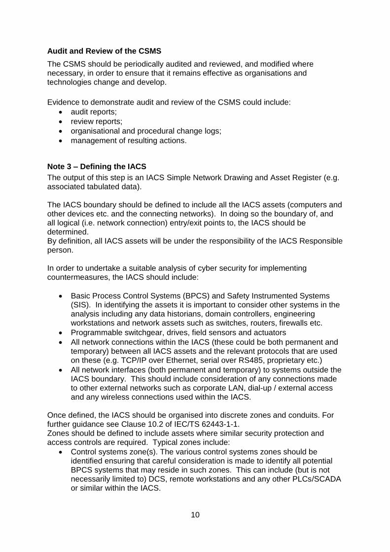
Audit and Review of the CSMS
The CSMS should be periodically audited and reviewed, and modified where necessary, in order to ensure that it remains effective as organisations and technologies change and develop.
Evidence to demonstrate audit and review of the CSMS could include:
audit reports;
review reports;
organisational and procedural change logs;
management of resulting actions.
Note 3 – Defining the IACS
The output of this step is an IACS Simple Network Drawing and Asset Register (e.g. associated tabulated data). The IACS boundary should be defined to include all the IACS assets (computers and other devices etc. and the connecting networks). In doing so the boundary of, and all logical (i.e. network connection) entry/exit points to, the IACS should be determined. By definition, all IACS assets will be under the responsibility of the IACS Responsible person. In order to undertake a suitable analysis of cyber security for implementing countermeasures, the IACS should include:
Basic Process Control Systems (BPCS) and Safety Instrumented Systems (SIS). In identifying the assets it is important to consider other systems in the analysis including any data historians, domain controllers, engineering workstations and network assets such as switches, routers, firewalls etc.
Programmable switchgear, drives, field sensors and actuators
All network connections within the IACS (these could be both permanent and temporary) between all IACS assets and the relevant protocols that are used on these (e.g. TCP/IP over Ethernet, serial over RS485, proprietary etc.)
All network interfaces (both permanent and temporary) to systems outside the IACS boundary. This should include consideration of any connections made to other external networks such as corporate LAN, dial-up / external access and any wireless connections used within the IACS.
Once defined, the IACS should be organised into discrete zones and conduits. For further guidance see Clause 10.2 of IEC/TS 62443-1-1. Zones should be defined to include assets where similar security protection and access controls are required. Typical zones include:
Control systems zone(s). The various control systems zones should be identified ensuring that careful consideration is made to identify all potential BPCS systems that may reside in such zones. This can include (but is not necessarily limited to) DCS, remote workstations and any other PLCs/SCADA or similar within the IACS.

11
Safety systems zone(s). These should include all SIS. As the SIS normally contains significant risk reduction control measures, it is usually appropriate to apply stronger controls to the SIS than the rest of the IACS (see Notes 5 and 6).
Note that where IACS are implemented in a virtual machine environment (e.g. operator interfaces), the security of that environment must also be considered.
Other zone(s). Other zones that include relevant assets should be identified, for example smart MCC devices, packaged systems etc.
Plant information zone(s). Other systems should be considered within the analysis including any data historians; engineering workstations etc. and include these in the plant information zone.
Once the zones have been identified, conduits can be defined:
Internal conduits(s), i.e. network connections between IACS zones.
External conduit(s), i.e. network connections to external systems outside of the identified IACS boundary. Again, it is important to note that this should include any wireless connections and also any external temporary connections.
No conduits are to be defined within an individual zone. Definition of these zones should be considered on a case-by-case basis depending upon relevant factors. These factors could include: the size and scope of the IACS, criticality of assets, operational function, geographic or logical location, required access (for example, least privilege principles), corporate standards or the department or organisation responsible for particular assets. The definition of the zones should receive suitable consideration as it is likely that data transfer between zones will be more strictly controlled and therefore each zone should be self-sufficient as far as is practicable, to facilitate the application of the protection measures (e.g. firewalls) without compromising operational needs. The zones should be defined in a hierarchical structure such that ‘defence in depth’ is achieved i.e. more critical control and safety zones lower in the hierarchy (therefore least susceptible to cyber threats from the corporate network), and connections to external systems at higher levels in the hierarchy. It is sometimes good practice to define a top-level in the hierarchy as a demilitarised zone (DMZ), which is sometimes also referred to as a perimeter network, and is used to connect to external networks such as the corporate LAN to allow access to specific services (typically historian data etc.). For most sites where there is at least one external connection (e.g. to the corporate LAN) then it is expected that there will normally be at least a control system zone, a process information zone and a safety system zone. Examples of zoning are shown in Appendix 2. There is also further guidance in IEC/TS 62443-1-1. The term ‘air-gapped’ is often used for systems that have no physical network connections to other systems. For example, an IACS would be considered ‘air-

12
gapped’ from another network if there were no conduits (permanent or temporary) between the IACS and any other device that was connected to that network. This does not however eliminate the risk, as malware can still be imported (e.g. via USB drives and maintenance laptops) and therefore other risk control measures need to be applied. The definition of the IACS should be documented as the IACS simple network drawing(s) showing the IACS zones and conduits and the IACS Asset Register. Whilst it may be useful to show non-IACS zones (e.g. the corporate network) on the IACS simple network drawing, the IACS Asset Register should only include IACS assets. The IACS Asset Register should:
For each zone, list all workstation, server, device etc. and types along with operating system types and versions, applications installed and versions.
For each conduit, the connection type (e.g. redundant Ethernet, RS-485), protocols used (e.g. TCP/IP, Modbus) and connection port information.
Note 4 –Risk Assessment
The output of this step is an assessment of major accident risk based on the IACS simple network drawing and asset register. The purpose of the risk assessment process is to determine the vulnerability of each IACS zone to the range of security threats so as to allow the appropriate countermeasures to be selected (see Notes 5 and 6). Typical IACS security threats include:
• Social engineering, phishing, water holing, ransomware, scanning, spear-phishing
• Malware, such as worms and viruses via the network, transportable media (e.g. USB sticks etc.), and via temporary connections (e.g. vendor laptops)
• Exploitation of vulnerabilities due to software errors, e.g. in the system firmware.
• Unauthorised access (local / remote). • Unauthorised actions by employees or by others, e.g. vendors. • Unauthorised data transfer, e.g. by USB connection. • Unintended employee actions. • Denial of service. • Sabotage of systems. • Theft.
Traditional risk assessment processes determine the potential major accident consequences for a range of initiating events (e.g. due to equipment, control or human failure) and their likelihood. The scope and integrity of risk reduction measures necessary can then be specified to reduce the risk to ALARP. For security threats, it is more difficult to determine the specific potential major accident consequence of each threat or its likelihood without detailed analysis on an on-going basis as threats, and vulnerabilities to threats, change over time and past history is no indication of future likelihood.

13
The approach adopted in this Operational Guidance allows for identification of proportionate expectations for countermeasures and architecture practices in order to provide:
• a minimum benchmark against which to assess the suitability and sufficiency of a duty holder’s risk assessment(s);
• an objective basis for expected countermeasures (see Note 5); • an example approach to the assessment of risk.
The risk assessment approach is shown in Appendix 3: Risk Assessment. To carry out a suitable and sufficient risk assessment will typically require a range of competencies. This might include the IACS Responsible Person, IACS system vendor representatives and other specialists. This should be recorded within the IACS risk assessment document. A duty holder may have adopted a similar approach to the risk assessment approach shown in Appendix 3 and assigned a risk category for each identified zone. Duty holders may adopt alternative approaches to risk assessment which would have to be assessed on a case-by-case basis. The adequacy of such a risk assessment should be assessed by considering the output of the risk assessment against the output of the risk assessment in this guidance as shown in Appendix 4: Security Countermeasures. Note that a duty holder may have chosen to apply more stringent countermeasures for business continuity / data protection and protection of national infrastructure reasons. The assessment could be completed in a simple tabular form, or other similar approach, for example a bow-tie diagram. The results should be included in the IACS Risk Assessment. This document should be stored securely and access limited to authorised personnel only.
Note 5 – Define and Implement Countermeasures
The outputs of this step are: • an updated IACS Risk Assessment showing:
• the security countermeasures required for the IACS assets and, where necessary, plans for their implementation.
• for existing (legacy) systems, records showing what security countermeasures have not been implemented along with justification for not implementing
• a revised IACS simple network drawing and asset register based on the countermeasures deployed as a consequence of the risk assessment;
• verification that no serious deficiencies remain in the countermeasures to control the major accident hazard.

14
For each IACS asset (device, workstation, server, network connection or grouping of these where appropriate), the countermeasures to be applied should be defined based upon the risk for the zone determined in the risk assessment.
The risk assessment should provide a benchmark for assessing the adequacy of the duty holder’s countermeasures and an example is given in Appendix 3: Risk Assessment. Examples of the countermeasures which could be expected to be used following the risk assessment are given in Appendix 4: Security Countermeasures. It may be necessary to modify the definition of the zones and conduits, for example to move assets associated with higher risk or that are more vulnerable, to a different zone to target the control measures. However, this must be balanced with operational performance requirements (e.g. time-critical data transfer between assets) and for management and standardisation etc. Any changes should be reflected in the IACS Simple Network Drawing and Asset Register. If it is found necessary to apply countermeasures to assets outside the IACS boundary in order to protect the IACS, then it may be necessary to move, split or duplicate assets so that the countermeasures can be applied within the IACS boundary and be managed under the IACS CSMS. A hierarchical approach should be adopted, for example prioritising implementation of measures such as inherent resilience, and prevention (e.g. physical security controls, authorisation and authentication) over other measures for detection. No single security countermeasure provides absolute protection as new threats and vulnerabilities can be identified at any time. To reduce these risks, implementing multiple protection measures in series, i.e. defence in depth, avoids single point failures. There are often also ‘quick-wins’ that are clearly reasonably practicable (typically they would be things like physical protection, USB and network port blocking, disabling of unused network switch ports, changing of default passwords and enforcement of password policies) that can be readily implemented. The IACS Risk Assessment, IACS Simple Network Drawing and / or IACS Asset Register should be updated to show which countermeasures have been applied to each asset (including conduits). For existing (legacy) IACS, a gap assessment may be produced showing what measures are already in place and what further measures need to be applied. This should be recorded on the IACS Risk Assessment, IACS Simple Network Drawing and / or IACS Asset Register and should include time-bound implementation plans. It may not be practicable to implement some of the countermeasures (especially for existing legacy systems e.g. due to their proprietary nature or age). In such cases alternative countermeasures to address the remaining vulnerabilities and risks should be considered and in particular to ensure that no serious deficiencies remain.

15
The outcomes should be recorded within the IACS Risk Assessment, IACS Simple Network Drawing and / or IACS Asset Register. For any remaining gaps, the justification for not implementing any countermeasures, and other countermeasures considered etc. should be recorded in the IACS Risk Assessment, IACS Simple Network Drawing and / or IACS Asset Register including records made to ensure that the countermeasures are considered in any future system upgrade projects or as part of obsolescence management. The updated IACS Risk Assessment, Simple network drawing and Asset Register should be stored securely and access limited to authorised personnel only. The cyber security landscape including the range of countermeasures available changes frequently and therefore the IACS Risk Assessment including countermeasures should be reviewed periodically.
Note 6 – Safety Instrumented Systems (SIS)
The output of this step is an updated IACS Risk Assessment that records the application of countermeasures considered for SIS and any relevant justification for not implementing them. For the purposes of this note, SIS shall include high integrity (PFD<0.1) layers of protection, or layers of protection of undefined integrity and any other systems that are capable of manipulating them. The countermeasures for SIS are the same as for the wider IACS and have been covered in Note 5 above. However, it is recognised that the SIS may provide significant risk reduction against many major accident hazards and their protection against cyber security attacks is therefore particularly important. The duty holder should therefore give additional consideration to the application of the countermeasures applied to the SIS, for example as shown in Appendix 5: Additional SIS Considerations. The results of such considerations should be recorded within the IACS Risk Assessment, IACS Simple Network Drawing and / or IACS Asset Register. Note that the requirement to address cyber security threats for SIS in clause 8.2.4 of BS EN 61511 (edition 2) may be met by following the process detailed in this Operational Guidance. Application of security measures to the SIS should be incorporated into the defined SIS lifecycle (see BS EN 61511 edition 2) for both new and installed SIS. Additional guidance is provided in “ISA-TR84.00.09-2013- Security Countermeasures Related to Safety Instrumented Systems”.

16
Glossary of terms
ALARP As Low as Reasonably Practicable
ATG Automatic Tank Gauging System
BPCS Basic Process Control System
CCR Central control room
COTS Commercial Off The Shelf
DCS Distributed Control System
DMZ Demilitarised Zone – a DMZ is a physical or logical sub network that contains and exposes external-facing services (in this case limited IACS services) to a larger and less trusted network (in this case normally the corporate LAN which is connected to the internet). The purpose of a DMZ is to add an additional layer of security. If properly configured, an external attacker would only have direct access to equipment in the DMZ, rather than any other part of the network.
Duty holder The person(s) or corporate body that has legal duties under relevant legislation. In the context of this guidance it will typically be the IACS owner or the IACS operator.
EEMUA The Engineering Equipment and Materials Users’ Association
FAT Forensic analysis tools
FTE Fault Tolerant Ethernet
HAZOP Hazard & Operability Studies
HMI Human Machine Interface
HSE Health & Safety Executive
IACS Industrial Automation and Control System including Safety Instrumented Systems
IDS Intrusion detection System
IPS Intrusion prevention system
IT Information Technology
LAN Local Area Network
Major Hazard Workplace
Any place regulated under the legislation defined in the ‘relevant regulations’ section of this operational guidance
PFD Probability of Failure on Demand
PHR Process Hazard Risk Analysis
Physical and Environmental Security
Protection of IACS assets (i.e. computers, networks, information and operations equipment) against unauthorised access or misuse.
PLC Programmable logic controller
Responsible Person
Person or group of persons responsible for IACS security (typically not under the management controls of an IT department)
SCADA Supervisory Control and Data Acquisition
SIL Safety Integrity Level
SIS Safety Instrumented System

17
Virtual Machine Environment
One instance of an operating system (which could be a thin-client or full operating system), for example running a SCADA operator interface application, running in an isolated partition of a computer to allow multiple applications to run at one time without interfering with each other. The virtual machine may be part of the IACS and therefore measures should be taken to protect the security of the IACS.
VLAN Virtual Local Area Network
VPN Virtual private network
WLAN Wireless local area network (also known as WiFi) Reference should also be made to IEC/TR 62443-1-2 for a full definition of terms and abbreviations used in this document.
18
Appendix 2: Example Simple Network Drawings
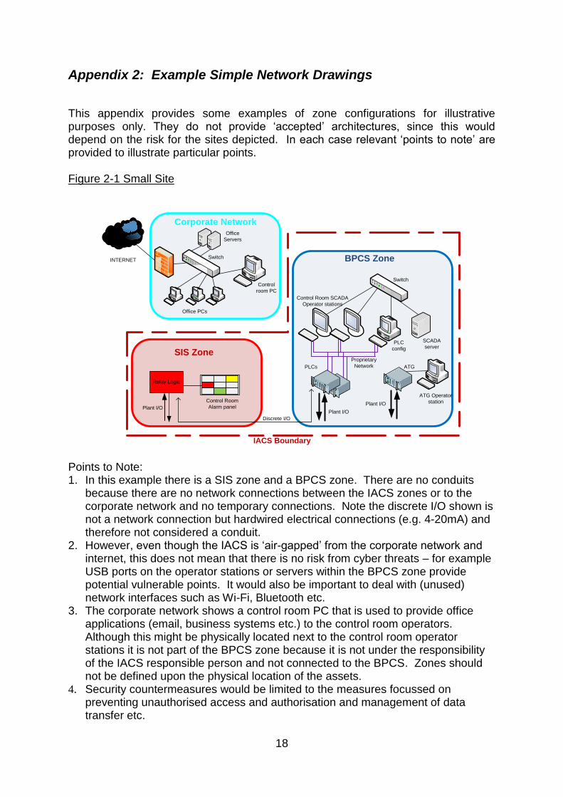
This appendix provides some examples of zone configurations for illustrative purposes only. They do not provide ‘accepted’ architectures, since this would depend on the risk for the sites depicted. In each case relevant ‘points to note’ are provided to illustrate particular points. Figure 2-1 Small Site
Points to Note: 1. In this example there is a SIS zone and a BPCS zone. There are no conduits
because there are no network connections between the IACS zones or to the corporate network and no temporary connections. Note the discrete I/O shown is not a network connection but hardwired electrical connections (e.g. 4-20mA) and therefore not considered a conduit.
2. However, even though the IACS is ‘air-gapped’ from the corporate network and internet, this does not mean that there is no risk from cyber threats – for example USB ports on the operator stations or servers within the BPCS zone provide potential vulnerable points. It would also be important to deal with (unused) network interfaces such as Wi-Fi, Bluetooth etc.
3. The corporate network shows a control room PC that is used to provide office applications (email, business systems etc.) to the control room operators. Although this might be physically located next to the control room operator stations it is not part of the BPCS zone because it is not under the responsibility of the IACS responsible person and not connected to the BPCS. Zones should not be defined upon the physical location of the assets.
4. Security countermeasures would be limited to the measures focussed on preventing unauthorised access and authorisation and management of data transfer etc.
BPCS Zone
Discrete I/O
PLC
configSIS Zone
Control Room
Alarm panelPlant I/O
SCADA
server
Control
room PC
Corporate Network
INTERNET
IACS Boundary
Relay Logic
PLCs ATG
ATG Operator
stationPlant I/O
Plant I/O
Office PCs
Office
Servers
Control Room SCADA
Operator stations
Switch
Switch
Proprietary
Network

19
Figure 2-2 Medium sized Site
Points to Note: 1. In this example for a medium sized site (where the BPCS is all on a single
network) there is a SIS zone, a BPCS zone and a plant information zone (PIZ). 2. There is a conduit between the BPCS zone and the SIS zone, presumably to
provide read only data from the SIS to the BPCS. However, since this a point-to-point serial read-only data type of connection no firewall is required. Note the discrete I/O shown is not a network connection but hardwired electrical connections (e.g. 4-20mA) and therefore not considered a conduit.
3. There is an external conduit between the PIZ and the corporate network for the purposes of allowing historian data (from the IACS) to be viewed on the office PCs. IACS historian data is captured on the PIZ Historian server. Note that there is also a historian server on the corporate network which provides data to the office PCs. This allows the PIZ firewall to be configured to limit access only
BPCS Zone
Engineering
Workstation
(temporary
connection)
HMI
SIS Logic
Solver
Serial I/O
Discrete I/O
Plant
I/O
Engineering
Workstation
SIS Zone
BPCS
Contrtollers
Plant I/O
Local Operator
Station
Plant Information Zone
Domain
ControllerHistorian
Server
Application
Server
PLC
PLC
Interface
Serial I/O
Control Room
Operation Stations
Corporate Network
INTERNET
WLAN
IACS Boundary
Relay
Logic
Wireless Devices
Field tablets
Remote I/O
Etc.
Historian
Server
Switch
Switch
Conduit
Conduit
Router
Firewall
Router
Firewall
Router
Firewall
Switch
Office
Servers
Office PCs
Switch
Conduit
Plant
I/O
Plant
I/O
Conduit

20
between the two historians and therefore minimise threats from other connections.
4. There is just one firewall between the PIZ and corporate network but importantly it is within the IACS boundary and therefore subject to management controls of the IACS. (Some corporate network rules may not allow this and therefore would also require a firewall on the corporate side).
5. A wireless zone is in use and therefore it would be necessary to secure this with encryption. It would also be important to deal with (unused) network interfaces such as Wi-Fi, Bluetooth etc.
6. A temporary connection is provided for an engineering laptop within the SIS zone. Both the laptop and connection would need to be managed to prevent unauthorised access and introduction of malware etc.

21
Figure 2-3 Large Site
Points to Note: 1. This example shows a larger, more complex site with a range of configurations. 2. Plant A BPCS zone does not have a firewall but the real-time operating systems
are isolated – this may be acceptable depending upon the vulnerabilities etc. 3. Plant A SIS zone is protected by OPC firewalls. 4. Plant B zone includes combined SIS and BPCS equipment and so the whole
zone would be subject to the more stringent SIS controls (e.g. physical protection and authorisation controls).
5. A DMZ zone is also used to provide historian services to the corporate network from all IACS plants as well as provide data transfer between the IACS and corporate network under strict controls thus no removable media is required to transfer data.
6. The top level zone is labelled as a CCR zone – this has some aspects of both the PIZ and BPCS zone in the previous example, the naming can reflect local usage.
7. There is serial I/O between the DCS and the PLC – presumably for data transfer / remote monitoring.
8. A wireless zone is in use and therefore it would be necessary to secure this with encryption. It would also be important to deal with (unused) network interfaces such as Wi-Fi, Bluetooth etc.
DMZ Zone
Historian
Server
Corporate Network
WLAN
IACS Boundary
Plant A BPCS Zone
Plant I/O
Local
Operator
Station
PLC
Serial I/OPlant I/O
DCS
Plant
I/O
Plant A SIS Zone
Safety
PLCs
Smart MCC
Serial I/O
Engineering
Workstation
(in equip room)
Safety
FTE
OPC
Plant B Zone
Plant I/O
DCS / SIS
Fieldbus
RoutersLocal Operator
Station
Smart
MCC
Engineering
Workstations
Unit 1 CCR Zone
Domain
ControllerHistorian Application
Server
Control Room
Operation Stations
Plant Z
Zone
Plant Y
SIS
Zone
Plant X
BPCS
Zone
Unit 2 CCR Zone
Data
Transfer
Server
INTERNET
Switch
Switch
Switch
Switch
Network
Interfaces
Router
Firewall
Router
Firewalls
Router
Firewalls
Router
Firewall
Office PCs
Office
Servers
Conduit
Conduit Conduit
Conduit
Conduit
Conduit
Proprietary
Network
Wireless I/OConduit

22
Figure 2-4 Remote Site
Points to Note: 1. In this example, there is a centralised control room with a remote operating site. 2. In this case a VPN solution is shown with data going over a public network. VPN
would not be required if a secure private (leased line) or point-to-point satellite / radio link was used – firewalls, with usual authorisation and authentication countermeasures etc. would be sufficient.
3. The remote zone also has requirements for a service engineer to connect a corporate laptop to the corporate network – segregation is achieved using VLANs, although a separate VPN would be another solution.
4. The VPN zone is within the IACS boundary to ensure that its configuration is controlled under the IACS cyber security management systems – it would be necessary to ensure that the VPN configuration would not allow the IACS network to be compromised by the corporate network – it is assumed that the VPN devices also provide necessary firewall functionality.
5. There is serial I/O between the SIS relay logic and the PLC – presumably indicating some sort of multiplexing device.
6. It would also be important to deal with (unused) network interfaces such as Wi-Fi, Bluetooth etc.
Engineering
Workstation
Central Control Room
Historian
Control Room
Operation Stations
Corporate Network
INTERNET
WLAN
IACS Boundary
Remote Zone
PLC
config
Plant I/O
SCADA
server
SIS
Relay
Logic
Plant I/O
Serial I/OSmart MCC
VPN
Corporate
Laptop
VLAN1
VLAN2
VPN Zone
VPN
Public
Network /
Satellite /
Radio etc.
VLAN2
VLAN1
Switch
Switch
SwitchSwitch
Router
Firewall
Router
Firewall
Router
Firewall
PLC
PLC
Interface
Conduit
Conduit
Conduit
Conduit
Office PCs
Office
Servers
Proprietary
Network
Router
Firewall

23
Appendix 3: Risk Assessment
The following is a risk assessment for a generic major accident workplace in order to establish proportionate expectations for countermeasures and architecture practices. Although not its primary purpose, it may be useful to duty holders as an illustrative example of one method of assessing risk and defining countermeasures and architecture practices. The general concept of the risk assessment is to identify systems that implement high integrity layers of protection against major accidents and afford them proportionately high levels of countermeasure based upon:
• BS EN 61511, in particular, the concepts of layers of protection and safety integrity;
• BS IEC 62443-2-1. The objectives of the following risk assessment are to:
• protect systems that provide layers of protection against major accidents; • take a precautionary approach without unnecessarily precluding beneficial
technologies. • allow the risk assessment to be re-calibrated as technologies develop
alongside intelligence on threats and vulnerabilities. It is not intended that the assessment be complex, but sufficient to identify which assets are vulnerable to which threats so as to determine what countermeasures should be applied. BS IEC 62443-2-1 (see appendices) provides an informative framework for a high level risk assessment that is intended to be calibrated for each situation. Calibration of the example high-level risk assessment from BS IEC 62443-2-1 for a major accident Likelihood The calibration of likelihood is based on current instances of attacks on, and vulnerabilities of, industrial and commercial systems. Table 3.1 - likelihood scale calibrated for a generic major accident
Likelihood
Category Justification for selection
High High likelihood chosen on the following basis:
Because of the uncertainty about future likelihood of threats and the unknown nature of the threats, this operational guidance uses a conservative probability for major accident risks.
Known instances of attacks on commercial systems and IACS.
Relevant recent examples of threats to, and vulnerabilities of, IACS

24
Consequence The calibration of consequence is predicated on the application of BS EN 61511, in particular, on an existing framework of independent layers of protection. This allows the assessment to consider failures of layers of protection as intermediate consequences whilst recognising that the ultimate consequence remains a major accident. It therefore allows a scale of consequence to be related to the required integrity of layers of protection. Table 3.2 - consequence scale calibrated for a generic major accident
Consequence
Category Major Accident
A (High)
Failure of or unauthorised access to a high integrity layer (PFD<0.1) of protection, including systems that are capable of manipulating this layer of
protection
Failure of or unauthorised access to a layer of protection of undefined integrity, including systems that are capable of manipulating this layer of protection
B* (Medium)
Failure of or unauthorised access to a low integrity layer of protection (PFD≥0.1), including systems that are capable of manipulating this layer of
protection
Failure of or unauthorised access to a system that places a demand on a high integrity layer of protection, including systems that are capable of manipulating
this layer of protection
C (Low)
Failure of or unauthorised access to a system that does not have a safety function
* Operators may choose to treat basic process control systems as high consequence systems for the purpose of business continuity. Risk level The risk level is established by a simple combination of likelihood (Table 3.1) and consequence (Table 3.2). Table 3.3 - risk level matrix calibrated for a generic major accident
Consequence category
A B C
Likelihood High High-risk Medium-risk Low-risk

25
Appendix 4: Security Countermeasures
The following countermeasures are based on:
• the risk assessment of Note 4 and appendix 3;
• ISA‑TR62443‑3‑1 (99.03.01), Security for industrial automation and control systems, Security Technologies for Industrial Automation and
Control Systems, Draft 1, Edit 1, December 2012. Note - Clause numbers relating to the Security Countermeasures that are used in Appendices 4 and 5, Tables 4.1, 4.2 and 5.1 respectively are from this Draft document;
• other relevant countermeasures;
• consideration of countermeasures and architecture practices that address IACS-wide vulnerabilities, irrespective of localised risk. Examples could include virus and malicious code detection systems and the use of firewalls whose location will depend on the architecture and layout of the IACS;
• consideration of countermeasures and architecture practices for low-risk IACS / network / zones (i.e. where there are no defined safety functions) on the basis that traditional risk assessments may not have identified safety functions for cyber threats because they did not consider multiple contingencies (i.e. several things occurring at once) or threats that have malicious intent.
However, it should be noted that the cyber security landscape is a frequently changing and so the following list should not be seen as exhaustive.

26
Table 4.1 – Interpretation and Context of IACS Security Countermeasures
Measure Interpretation and Context Inherent Resilience Prior to considering the countermeasures (sections 5-10 below) the duty holder should consider
‘inherent resilience’. These measures typically require more IACS system-wide consideration of the network architecture and configuration / practices.
Elimination, reduction or substitution of vulnerable assets
In some cases it may be simpler and more cost effective to remove or not introduce assets or network connections that could pose a security risk or substitute them with ones less vulnerable to threats. For example:
Removal of remote operator terminals where operation could be achieved in other more secure ways such as hardwired local indicators or migration to a central control room.
Use of non-programmable systems in remote areas.
Air-gapping zones where there are no or minimal data transfer requirements. However, this consideration must be balanced with the need for operability and maintainability, for example:
Air-gapping a zone where data transfer is required for operation and maintenance reasons could increase security risks due to people using USB drives etc.
Non-programmable systems may not provide the required functionality / flexibility required leading to other risks.

27
Measure Interpretation and Context
Elimination, reduction or substitution of vulnerable configurations / practices
In some cases it is preferable to provide additional IACS assets so as to make the application of security risk controls easier and avoid configurations or practices that are inherently more vulnerable to threats. For example:
Provide an additional historian server on the corporate network that gathers data from the IACS historian rather than have all corporate PCs access the IACS network.
Provide a secure mechanism for transfer of files between the IACS and corporate network rather than permitting more uncontrolled access using CDs, USB drives etc.
For remote connections (e.g. vendor access) provide a controlled environment (e.g. laptop or virtual environment) rather than allowing the use of uncontrolled hardware / software.
Clause 5 Authentication and Authorization Technologies
Authorisation Any method that defines authorisation requirements for users based upon the principle of least access, i.e. only permitting access to competent personnel appointed to roles requiring that access (rather than based upon seniority for example). As a minimum, authorisation requirements for plant operators, engineers and systems administrators should be defined. Any third parties (e.g. vendor access) should also be covered. Standard authorisation techniques typically involve assigning permissions to users or groups of users and should be covered in the CSMS. Role based authorisation tools would be an acceptable technique but not widely implemented at this time in IACS (e.g. as described in clause 5.1).

28
Measure Interpretation and Context
Authentication Any method or combination of methods to confirm the identity of individuals that forms the basis for determining authorisation for access to the IACS and its assets and functions. See clauses:
5.2 Password Authentication
5.3 Challenge/Response Authentication
5.4 Physical/Token Authentication
5.5 Smart Card Authentication
5.6 Biometric Authentication
5.7 Location-Based Authentication Note – different methods may be appropriate for different roles. For example, control room operator stations may use a common operator username and password as access is controlled by physical location whereas remote access by engineers may require physical token authentication. Password policy describing password requirements, methods of distribution / change etc. should be implemented within the CSMS and should be consistent with the risk of the system being accessed and the vulnerability of the systems being considered. For example, more robust authentication would be appropriate to higher integrity parts of the IACS and where they are more inter-connected. Password Distribution and Management Technologies may be used (e.g. as described in clause 5.8) to facilitate more robust password management.
5.9 Device-to-Device Authentication Device to device authentication may have been built in to control systems and would not normally be a matter for the end-user. However, device-to-device authentication (including encryption where appropriate) should be employed in situations where connections are made across networks outside the IACS, for example remote sites or via a corporate network. This would include situations with central control rooms operating remote sites and situations where data is taken from the IACS network to the corporate network for data historian or remote engineering purposes.

29
Measure Interpretation and Context Clause 6 Filtering/Blocking/Access Control Technologies
6.1 Network Firewalls Firewalls should be implemented to limit network traffic between zones (i.e. where conduits are defined) using the concept of allowing only the minimum necessary traffic. A system-wide view needs to be considered when applying firewalls, for example when a firewall is deemed required for a particular zone, it may be appropriate to locate the firewall in a different zone (e.g. to better suit the requirements for administration of the firewall). Firewalls should always be implemented for conduits that connect to external networks, e.g. corporate networks. Typically there should also be firewalls between each layer of the zone hierarchy, although they may also be considered for any conduits in the same level. However, application of firewalls for conduits between zones of the IACS will need to be based upon the system design, the network connectivity required, the potential vulnerabilities of each zone and the other countermeasures in place. Where firewalls are implemented hardware firewalls are preferred being more secure and easier to configure / maintain. The configuration of all firewalls should be appropriately documented, tested and changes managed as part of the CSMS.
6.2 Host-based Firewalls Not widely implemented in IACS environments. May be useful where network firewalls cannot be implemented.
6.3 Virtual Networks Not recommended for managing security issues, although may be used in combination with other security measures (e.g. VPNs) for communication to remote zones. However, VLANs may be used in some control systems / fieldbus architectures. Where they are used, VLANs should not be used as the only method to control traffic over conduits.
Clause 7 Encryption Technologies and Data Validation
Note – where encryption technologies are used key management (e.g., secure key generation, distribution, certification etc.) will need to be managed as part of the CSMS.

30
Measure Interpretation and Context
7.1 Symmetric (Secret) Key Encryption Not widely available for IACS local networks, although may be implemented in future. Must be used where connectivity is accessible outside the IACS secure area, for example:
Where wireless (WIFI) is used, e.g. wireless instrumentation
Where remote access is granted, e.g. for vendor service access
7.2 Public Key Encryption and Key Distribution
Not widely available for IACS networks, although may be implemented in future. May be useful in situations where encryption is required but symmetric secret key encryption is not possible, depending upon the performance requirements and other requirements.
7.3 Virtual Private Networks (VPNs) VPNs are one way of allowing access to remote sites more securely. Where VPNs are used, their configuration (including user and access rights) must be documented, tested, kept up-to-date and changes managed.
Clause 8 Management, Audit, Measurement, Monitoring, and Detection Tools
8.1 Log Auditing Utilities Periodic review of available system and security logs available on workstations and network devices (e.g. firewalls). Establish baselines of what ‘normal’ looks like to help identify attacks.
8.2 Virus and Malicious Code Detection Systems
Installation, maintenance (keeping virus definitions up to date) and monitoring of anti-virus/malware tools on workstations, servers and devices. In particular use of these systems on any removable media
8.3 Intrusion Detection Systems Installation and monitoring of intrusion detection systems on key workstations, servers or network devices connected to external networks. Identification and investigation of abnormal activity.
8.4 Vulnerability Scanners Vulnerability scanning remains a challenge in operating environments such as IACS. Opportunistic and appropriate use may be considered so as not to affect online systems.

31
Measure Interpretation and Context
8.5 Forensics and Analysis Tools (FAT) Deployment of FAT to detect and respond to unusual network activity.
8.6 Host Configuration Management Tools Use of these tools is often not applicable to IACS at this time but may become applicable in future.
8.7 Automated Software Management Tools Use of these tools may be effective in managing software deployment / management, especially on larger systems and where COTS are used, for example to roll out security updates etc. May become more applicable in future.
Clause 9 Industrial Automation and Control Systems Computer Software
9.1 Server and Workstation Operating Systems
Use of COTS operating systems is widespread on server and workstations, although high-security implementations may become available in future. This requires that the following steps are taken:
1. All unnecessary services are disabled, especially those that allow remote access (e.g. FTP, remote terminal access, etc.)
2. Removal of all unnecessary applications / software. Provision of corporate applications (email, web access, corporate documents, office applications etc.) should normally be provided by workstations outside of the IACS boundary (even if they are physically located in the control room etc.).
3. Default passwords (both vendor and operating system) are changed / disabled. 4. Disabling unused ports, e.g. USB, networks ports etc. 5. Security updates / patches are managed. 6. Backups of operating systems and configurations taken regularly and restoration tested.
32
Measure Interpretation and Context
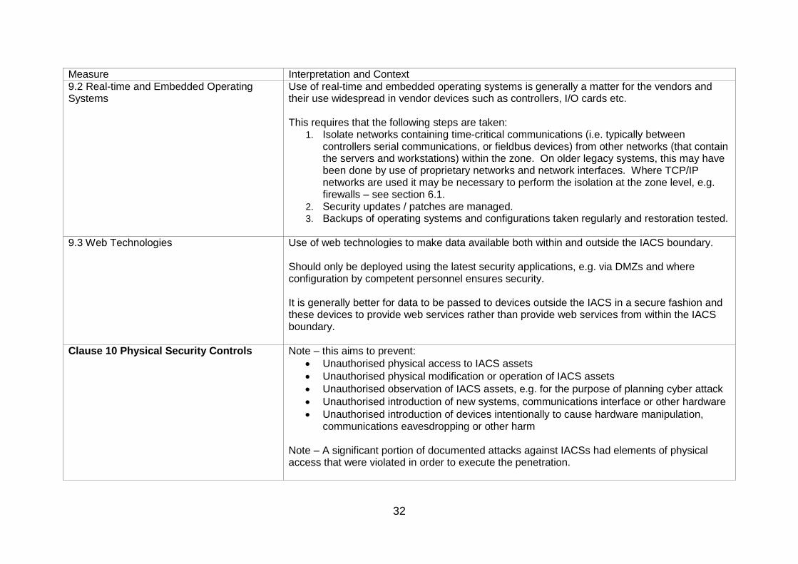
9.2 Real-time and Embedded Operating Systems
Use of real-time and embedded operating systems is generally a matter for the vendors and their use widespread in vendor devices such as controllers, I/O cards etc. This requires that the following steps are taken:
1. Isolate networks containing time-critical communications (i.e. typically between controllers serial communications, or fieldbus devices) from other networks (that contain the servers and workstations) within the zone. On older legacy systems, this may have been done by use of proprietary networks and network interfaces. Where TCP/IP networks are used it may be necessary to perform the isolation at the zone level, e.g. firewalls – see section 6.1.
2. Security updates / patches are managed. 3. Backups of operating systems and configurations taken regularly and restoration tested.
9.3 Web Technologies Use of web technologies to make data available both within and outside the IACS boundary. Should only be deployed using the latest security applications, e.g. via DMZs and where configuration by competent personnel ensures security. It is generally better for data to be passed to devices outside the IACS in a secure fashion and these devices to provide web services rather than provide web services from within the IACS boundary.
Clause 10 Physical Security Controls Note – this aims to prevent:
Unauthorised physical access to IACS assets
Unauthorised physical modification or operation of IACS assets
Unauthorised observation of IACS assets, e.g. for the purpose of planning cyber attack
Unauthorised introduction of new systems, communications interface or other hardware
Unauthorised introduction of devices intentionally to cause hardware manipulation, communications eavesdropping or other harm
Note – A significant portion of documented attacks against IACSs had elements of physical access that were violated in order to execute the penetration.
33
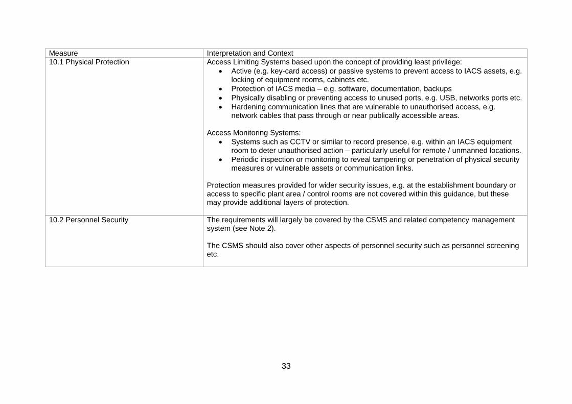
Measure Interpretation and Context
10.1 Physical Protection Access Limiting Systems based upon the concept of providing least privilege:
Active (e.g. key-card access) or passive systems to prevent access to IACS assets, e.g. locking of equipment rooms, cabinets etc.
Protection of IACS media – e.g. software, documentation, backups
Physically disabling or preventing access to unused ports, e.g. USB, networks ports etc.
Hardening communication lines that are vulnerable to unauthorised access, e.g. network cables that pass through or near publically accessible areas.
Access Monitoring Systems:
Systems such as CCTV or similar to record presence, e.g. within an IACS equipment room to deter unauthorised action – particularly useful for remote / unmanned locations.
Periodic inspection or monitoring to reveal tampering or penetration of physical security measures or vulnerable assets or communication links.
Protection measures provided for wider security issues, e.g. at the establishment boundary or access to specific plant area / control rooms are not covered within this guidance, but these may provide additional layers of protection.
10.2 Personnel Security The requirements will largely be covered by the CSMS and related competency management system (see Note 2). The CSMS should also cover other aspects of personnel security such as personnel screening etc.

34
Table 4.2 - expected major accident countermeasures and practices based on IACS risk levels Where: For countermeasures: Required: deployment of the countermeasure is expected – the countermeasure should be deployed unless the existing system or proposed system does not support the measure. Recommended: deployment of the countermeasure is expected unless:
the existing system or proposed system does not support the measure, or
It is clearly not reasonably practicable, or
It is clearly not desirable on the basis of overall risk, or
Other ‘optional’ measures have been taken to address relevant vulnerabilities. Optional: deployment of the countermeasure is at the discretion of the duty holder but should be considered:
To address vulnerabilities where the required / recommended measure could not be implemented
Where already available to improve overall security
To address other risks (e.g. commercial) at the operators discretion
For architecture practices: Not allowed: the architecture practice should not be deployed. May be allowed: the architecture practice may be deployed if supported by an assessment to show that relevant security vulnerabilities have been addressed.

35
Countermeasure and architecture practices
For guidance and context on the use of these terms, see Table 4.1.
High-risk IACS / network / zone
Medium-risk IACS / network / zone
Low-risk IACS / network / zone
Inherent Resilience
Elimination, reduction or substitution of vulnerable assets Required Required Required
Elimination, reduction or substitution of vulnerable configurations / practices
Required Required Required
Clause 5 Authentication and Authorization Technologies
Authentication Required Required Required
Authorisation Required Required Required
5.9 Device-to-Device Authentication Required Recommended Recommended
Clause 6 Filtering/Blocking/Access Control Technologies
6.1 Network Firewalls Recommended Recommended Recommended
6.2 Host-based Firewalls Optional Optional Optional
6.3 Virtual Networks Not allowed May be allowed May be allowed
Clause 7 Encryption Technologies and Data Validation
7.1 Symmetric (Secret) Key Encryption Required Recommended Recommended
7.2 Public Key Encryption and Key Distribution Optional Optional Optional
7.3 Virtual Private Networks (VPNs) May be allowed May be allowed May be allowed
Clause 8 Management, Audit, Measurement, Monitoring, and Detection Tools
8.1 Log Auditing Utilities Required Recommended Optional

36
Countermeasure and architecture practices
For guidance and context on the use of these terms, see Table 4.1.
High-risk IACS / network / zone
Medium-risk IACS / network / zone
Low-risk IACS / network / zone
8.2 Virus and Malicious Code Detection Systems Required Required Recommended
8.3 Intrusion Detection Systems Recommended Recommended Optional
8.4 Vulnerability Scanners Optional Optional Optional
8.5 Forensics and Analysis Tools (FAT) Optional Optional Optional
8.6 Host Configuration Management Tools Optional Optional Optional
8.7 Automated Software Management Tools Optional Optional Optional
Clause 9 Industrial Automation and Control Systems Computer Software
9.1 Server and Workstation Operating Systems May be allowed May be allowed May be allowed
9.2 Real-time and Embedded Operating Systems May be allowed May be allowed May be allowed
9.3 Web Technologies Not allowed May be allowed May be allowed
Clause 10 Physical Security Controls
10.1 Physical Protection Required Required Recommended
10.2 Personnel Security Required Required Recommended
37
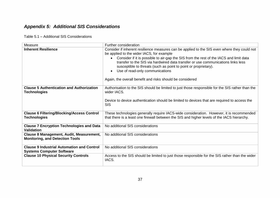
Appendix 5: Additional SIS Considerations Table 5.1 – Additional SIS Considerations Measure Further consideration Inherent Resilience Consider if inherent resilience measures can be applied to the SIS even where they could not
be applied to the wider IACS, for example
Consider if it is possible to air-gap the SIS from the rest of the IACS and limit data transfer to the SIS via hardwired data transfer or use communications links less susceptible to threats (such as point to point or proprietary).
Use of read-only communications Again, the overall benefit and risks should be considered
Clause 5 Authentication and Authorization Technologies
Authorisation to the SIS should be limited to just those responsible for the SIS rather than the wider IACS. Device to device authentication should be limited to devices that are required to access the SIS
Clause 6 Filtering/Blocking/Access Control Technologies
These technologies generally require IACS-wide consideration. However, it is recommended that there is a least one firewall between the SIS and higher levels of the IACS hierarchy.
Clause 7 Encryption Technologies and Data Validation
No additional SIS considerations
Clause 8 Management, Audit, Measurement, Monitoring, and Detection Tools
No additional SIS considerations
Clause 9 Industrial Automation and Control Systems Computer Software
No additional SIS considerations
Clause 10 Physical Security Controls Access to the SIS should be limited to just those responsible for the SIS rather than the wider IACS.


![NFI – INDUSTRIAL AUTOMATION TRAINING ACADEMYnfiautomation.org/Six Months Industrial Automation Syllabus.pdf · [NFI – INDUSTRIAL AUTOMATION TRAINING ACADEMY] ... Motor Timing](https://img.dokumen.tips/doc/110x75/5af8aad47f8b9ad2208cd6bd/nfi-industrial-automation-training-months-industrial-automation-syllabuspdfnfi.jpg)