Embed Size (px)
DESCRIPTION
Design Guideline
Citation preview

Connell Wagner Pty Ltd ACN 005 139 873
Structural Design Guidelines February 2004

Structural Design Guidelines Connell Wagner Pty Ltd
Doc Ref: P:\9660\08\Design Guidelines\Table of Contents
Version No : 1.0 Issue Date : 29/10/97
1 of 10
Controlled Copies Issue Register
Office Copy Number Current Version No
Melbourne (Master) 0 1.0
Melbourne (Office) 1 1.0
Melbourne (Spare) 2 1.0
Sydney 3 1.0
Brisbane 4 1.0
Adelaide 5 1.0
Perth 6 1.0
Mackay 7 1.0
Newcastle 8 1.0
Wellington 9 1.0
Auckland 10 1.0
Gold Coast 11 1.0
Darwin 12 1.0

Structural Design Guidelines Connell Wagner Pty Ltd
Doc Ref: P:\9660\08\Design Guidelines\Table of Contents
Version No : 1.0 Issue Date : 29/10/97
2 of 10
TABLE OF CONTENTS Section
Version
Action Author
1.0 INTRODUCTION 1.0 Perth (GR)
2.0 DESIGN PRINCIPLES AND PROCEDURES 1.0 Melb
(JB) 2.1 Design Philosophy
2.2 Project Procedures
2.2.1 Introduction 2.2.2 Briefing 2.2.3 Preliminary design 2.2.4 Final design 2.2.5 Budget and Time 2.2.6 Computers 2.2.7 Computations 2.2.8 Drawings
2.3 Specifications 2.4 Problem Areas 2.5 Meetings 2.6 Correspondence 2.7 Checking
3.0 DESIGN LOADS 1.0 Perth
(PR) 3.1 Introduction
3.2 Codes 3.3 References 3.4 Technical Notes 3.5 Properties of Materials 3.6 Construction Loads
4.0 STRUCTURAL ANALYSIS 1.0 Melb
(PL) 4.1 Introduction
4.2 Codes 4.3 References 4.4 Technical Notes 4.5 Input
4.5.1 Load Estimation 4.5.2 Load Summary 4.5.3 Design Criteria
4.6 Model Selection 4.7 Analysis
Structural Design Guidelines Connell Wagner Pty Ltd
Doc Ref: P:\9660\08\Design Guidelines\Table of Contents
Version No : 1.0 Issue Date : 29/10/97
3 of 10
Section
Version
Action Author
4.7.1 Analysis of Concrete Frames 4.7.2 Analysis of Steel Frames 4.7.3 Analysis of brickwork Panels 4.7.4 Computer Analysis 4.7.5 Formulae for Estimation of Beam Frame
Shear, Moment and Deflection
4.7.6 Formulae of Plates and Tanks 4.7.7 Analysis of Irregular shaped concrete
columns 4.7.8 Analysis of Structures for Fatigue 4.7.9 Section Property Analysis
4.8 Verification of Analysis 5.0 REINFORCED & PRESTRESSED CONCRETE 1.0 Syd
(MB) 5.1 Introduction
5.2 References 5.3 Technical Notes 5.4 Reinforced Concrete Floor Systems
5.4.1 General 5.4.2 Flexural Member Size Selection 5.4.3 Typical Reinforcement Quantities 5.4.4 Deflection Limitations 5.4.5 Flat Slabs and Flat Plates 5.4.6 Banded Slabs 5.4.7 Precast Floor Systems 5.4.8 Reinforced Concrete Beams
5.5 Prestressed Concrete Floor System 5.5.1 General
5.5.2 Design Check List 5.5.3 Analysis 5.5.4 Deflection Limitations 5.5.5 Prestressing Tendons and Details 5.5.6 Flat Slab Design 5.5.7 Banded Slab Design 5.5.8 Earthquake Detailing
5.6 Reinforced Concrete Column

Structural Design Guidelines Connell Wagner Pty Ltd
Doc Ref: P:\9660\08\Design Guidelines\Table of Contents
Version No : 1.0 Issue Date : 29/10/97
4 of 10
Section
Version
Action Author
5.6.1 Scope 5.6.2 Load Rundowns 5.6.3 Design Loads 5.6.4 Reinforcement 5.6.5 Concrete Strengths 5.6.6 Bending Moments 5.6.7 Slenderness Ratios 5.6.8 Fire Resistance and Cover 5.6.9 General Design Notes 5.6.10 Preliminary Design 5.6.11 Column ties 5.6.12 Column Starter Bars 5.6.13 Column Size Reductions 5.6.14 Top Terminations of Column
Reinforcement 5.6.15 Bundles Bars 5.6.16 Column Splices 5.6.17 Mechanical Tension Splices 5.6.18 Column Axial Shortening 5.6.19 High Strength Concrete 5.6.20 Bending Moments in Columns 5.6.21 Concrete Placing, Stripping and Curing
5.7 Reinforced Concrete Walls 5.7.1 Design Approach
5.7.2 Walls - Low to Medium Rise 5.7.3 Core Walls - High Rise (greater than 20
storeys) 5.7.4 Influence of Creep 5.7.5 Relaxation 5.7.6 Basement Retaining Walls
5.8 Foundations 5.8.1 Strip footings
5.8.2 Pad footings 5.8.3 Combined and Strapping Footings 5.8.4 Raft (or Mat) Footings 5.8.5 Pile Footings 5.8.6 Bored Piles 5.8.7 Driven Piles
5.9 Water Retaining Structures 5.9.1 Introduction
5.9.2 Design Philosophy 5.9.3 Design Analysis 5.9.4 Concrete Technology 5.9.5 Construction
5.10 Corbels, Dapped, Beams ends and Deep Beams
5.10.1 Corbels 5.10.2 Dapped Beams Ends 5.10.3 Deep Beams 5.10.4 Repairing Concrete

Structural Design Guidelines Connell Wagner Pty Ltd
Doc Ref: P:\9660\08\Design Guidelines\Table of Contents
Version No : 1.0 Issue Date : 29/10/97
5 of 10
Section
Version
Action Author
6.0 PRECAST CONCRETE 1.0 Adel (JW)
6.1 Introduction 6.2 Codes 6.3 References 6.4 Technical Notes 6.5 Design Principles
6.5.1 Non-Load Bearing Precast Cladding Panels
6.5.2 Design of Precast Concrete Panels 6.5.3 Finishes 6.5.4 Design Criteria for Fixings 6.5.5 Tolerances 6.5.6 Fixing Ferrules and Lifting Devices 6.5.7 Fixing and Design Aids 6.5.8 Prototypes 6.5.9 Notes to be Placed on the Precast
Drawings 6.5.10 Typical Panel Connections 6.5.11 Load Bearing Precast 6.5.12 Tilt-up Construction 6.5.13 Floor Panels 6.5.14 Detailing 6.5.15 Joints 6.5.16 Standard Details 6.5.17 Shop Drawings
7.0 STRUCTURAL STEELWORK 7.1 Introduction
7.2 Codes 7.3 References 7.4 Technical Notes 7.5 Purlins and Girts
7.5.1 Design 7.5.2 Use of Purlins and Girts
7.6 Beams 7.6.1 General
7.6.2 Connections 7.6.3 Effective Lengths, Moment Gradient 7.6.4 Members subject to Bending 7.6.5 Angles as Beams - Extract from
Reference (6) 7.6.6 Members Subject to Axial Compression 7.6.7 Members Subject to Combined Action 7.6.8 Penetrations 7.6.9 Allowable Deflections
7.7 Trusses
Structural Design Guidelines Connell Wagner Pty Ltd
Doc Ref: P:\9660\08\Design Guidelines\Table of Contents
Version No : 1.0 Issue Date : 29/10/97
6 of 10
Section
Version
Action Author
7.7.1 General 7.7.2 Analysis 7.7.3 Member Sizing 7.7.4 Connection 7.7.5 Fabrication, Transport and Erection 7.7.6 Weld Testing
7.8 Portal Frames 7.8.1 General
7.8.2 Rafters 7.8.3 Bean Columns 7.8.4 Columns 7.8.5 End Wall Mullions 7.8.6 Flybraces 7.8.7 Connections 7.8.8 Bracing 7.8.9 Roof Bracing 7.8.10 Wall Bracing 7.8.11 Temperature Range 7.8.12 Footings
7.9 Other Structural Forms 7.9.1 Space Frames
7.9.2 Cable Structures 7.9.3 Masts and Lattice Towers 7.9.4 Cold Formed Steel 7.9.5 Painting of Steelwork 7.9.6 Erection of Steelwork
8.0 COMPOSITE DESIGN 1.0 Melb
(MS) 8.1 Introduction
8.2 Codes 8.3 References 8.4 Technical Notes 8.5 Steel Beams
8.5.1 Composite Program - “COMPBEAM” 8.5.2 Dynamics 8.5.3 Composite Beam Deflections
8.6 Slabs 8.6.1 Design Method 8.7 Columns 8.7.1 Design Methods
8.7.2 Concrete Filled Steel Tubes
9.0 MASONRY 1.0 Adel
(JW)

Structural Design Guidelines Connell Wagner Pty Ltd
Doc Ref: P:\9660\08\Design Guidelines\Table of Contents
Version No : 1.0 Issue Date : 29/10/97
7 of 10
Section
Version
Action Author
9.1 Introduction 9.2 Codes 9.3 References 9.4 Technical Notes 9.5 Responsibility
9.5.1 General 9.5.2 Design/Documentation 9.5.3 Inspections
9.6 Loadings 9.6.1 Wind Loads
9.6.2 Earthquake Loads 9.6.3 Vertical Loads 9.6.4 Load Combinations
9.7 Design Details 9.7.1 Design of Control Joints
9.7.2 Design of Wall Ties 9.7.3 Fire Rating
9.8 Materials 9.8.1 Masonry
9.8.2 Mortar 9.8.3 Grout 9.8.4 Masonry 9.8.5 Reinforcement 9.8.6 Accessories
10.0 TIMBER DESIGN 1.0 Perth
(DP) 10.1 Introduction
10.2 Codes 10.3 References 10.4 Technical Notes 10.5 Availability 10.6 Timber Sizes
10.6.1 Moisture Content 10.6.2 Strength Grading 10.6.3 Creep 10.6.4 Durability 10.6.5 Differing Strength Characteristics
Perpendicular or Parallel to Grain
10.7 Designing Timber Structures 10.7.1 Beams
10.7.2 Trusses 10.7.3 Fabricated Plywood Elements 10.7.4 Joints
11.0 GLASS AND CURTAIN WALL DESIGN 1.0 Bris
(MK)

Structural Design Guidelines Connell Wagner Pty Ltd
Doc Ref: P:\9660\08\Design Guidelines\Table of Contents
Version No : 1.0 Issue Date : 29/10/97
8 of 10
Section
Version
Action Author
11.1 Introduction 11.2 Codes 11.3 References 11.4 Technical Note 11.5 Glass Design Principles
11.5.1 General 11.5.2 Mechanical Properties 11.5.3 Annealed Glass 11.5.4 Toughened Glass 11.5.5 Heat Strengthened Glass 11.5.6 Laminated Glass 11.5.7 Available Glass Thicknesses 11.5.8 Considerations in Glass Selection 11.5.9 Design of Glass for Wind Loading 11.5.10 Gravity Loading 11.5.11 Design for Human Impact 11.5.12 All-Glass Assemblages 11.5.13 Jointing 11.5.14 Aquaria and Underwater Observation
Panels
11.6 Curtain Wall Design Principles 11.6.1 Introduction
11.6.2 Factors Requiring Consideration 11.6.3 Building Movements 11.6.4 Building and Curtain Wall Tolerances 11.6.5 material Properties 11.6.6 Silicone Sealants 11.6.7 Structural Silicone 11.6.8 Curtain Wall Component Design 11.6.9 Structural Sealant Design 11.6.10 Structural Silicone Testing 11.6.11 Waterproofness
11.7 Curtain Wall Prototype Testing 11.8 Curtain Wall Fabrication and Erection 11.9 Quality Control and Inspection 11.10 Future Inspection and Maintenance 11.11 Curtain Walls - Connell Wagner’s Role 11.12 Curtain Wall Problems
12.0 NATURAL STONE 1.0 Adel
(JW) 12.1 Introduction
12.2 Codes 12.3 References 12.4 Technical Notes 12.5 Design Principles

Structural Design Guidelines Connell Wagner Pty Ltd
Doc Ref: P:\9660\08\Design Guidelines\Table of Contents
Version No : 1.0 Issue Date : 29/10/97
9 of 10
Section
Version
Action Author
12.5.1 General 12.5.2 Natural Stone Facade Claddings 12.5.3 Stone Selection 12.5.4 Properties of Building Stone 12.5.5 Testing 12.5.6 Allowable Stresses 12.5.7 Methods of Supporting Stone 12.5.8 Considerations in Setting Up a Stone
Supply Contract
13.0 ALUMINIUM 1.0 Bris
(MK) 13.1 Introduction
13.2 Codes 13.3 References 13.4 Technical Notes 13.5 Design Principles
13.5.1 Allowable Stresses 13.5.2 Fatigue 13.5.3 Thermal Movement 13.5.4 Connections 13.5.5 Dissimilar Materials 13.5.6 Chemical Corrosion Resistance
14.0 TENSILE MEMBRANE STRUCTURES 1.0 Melb
(MB) 14.1 Introduction
14.2 Codes 14.3 References 14.4 Technical Notes 14.5 Components
14.5.1 Membrane Material 14.5.2 Cables 14.5.3 Webbings 14.5.4 Fittings 14.5.5 Structural Steelwork 14.5.6 Foundations
14.6 Design Principles 14.6.1 Approximate Methods of Calculations
14.6.2 Formfinding 14.6.3 Design Loads 14.6.4 Analysis/Detailed Design/Patterning
15.0 GRC 1.0 Adel
(JW)
Structural Design Guidelines Connell Wagner Pty Ltd
Doc Ref: P:\9660\08\Design Guidelines\Table of Contents
Version No : 1.0 Issue Date : 29/10/97
10 of 10
Section
Version
Action Author
15.1 Introduction 15.2 Codes 15.3 References 15.4 Technical Notes 15.5 Design Principles
15.5.1 Materials 15.5.2 Glass Fibres 15.5.3 Quality Control 15.5.4 Production Methods 15.5.5 Methods of Transportation and On-Site
Handling 15.5.6 Mechanical and Physical Properties 15.5.7 Fixings 15.5.8 Surface Finishes 15.5.9 Waterproofness 15.5.10 Composite Panels
15.6 General Summary of Material 15.6.1 Typical Details for GRC 16.0 TEMPORARY WORKS DESIGN 1.0 Adel
(JW) 16.1 Introduction
16.2 Codes 16.3 References 16.4 Technical Notes 16.5 Design Principles
16.5.1 Design Considerations 16.5.2 Underpinning 16.5.3 Shoring 16.5.4 Retaining Walls 16.5.5 Temporary Supports (for Walls) 16.5.6 Crane Bases and Ties 16.5.7 Site Gantries 16.5.8 Demolition
APPENDIX A
Technical Report TR96-1 - Earthquake Design to AS1170.4
1.0
Adel (JW)
APPENDIX B Technical Report TR96-4 - Cable Structures
1.0
Melb (RG)
APPENDIX C Technical Report TR96-5 - The Development of a Prefabricated Steel Framed Housing System
1.0
Adel (AL)
APPENDIX D Technical Report TR96-6 - Introduction to Structural Aspects of Fire Engineering Crown Casino Experience
1.0
Melb (SD)

Structural Design Guidelines Connell Wagner Pty Ltd
Doc Ref: P:\9660\08\Design Guidelines\Table of Contents
Version No : 1.0 Issue Date : 29/10/97
11 of 10
APPENDIX E Technical Report TR97-1 - Concrete Facade Repairs and Maintenance
1.0
Adel (DJ)
Version Register
Version No Section Changed By Issue Date
1.0 Initial Issue All 29 October 1997

Structural Design Guidelines Connell Wagner Pty Ltd
Doc Ref: P:\9660\08\Design Guideline\Section1 to 4
Version No : 1.0 Issue Date : 29/10/97
1 of 2
1. INTRODUCTION
The Design Guidelines Manual has been produced as a ‘firm guideline’ for the
common structural design processes by Connell Wagner’s structural engineers.
The manual is focused on the structural design issues which confront the engineer in
day to day work. It is a technical document giving guidelines for structural analysis
and design for the common building materials used in today’s building and
construction industry.
The document has been collated to reflect Connell Wagner’s combined knowledge,
experience and expertise in structure engineering.
The manual presents a rational and balanced approach to design and is intended to
generate uniformity in the more standard day to day design exercises. This uniformity
should be both evident within a particular office and also across the whole
organisation.
The manual shall be used on a regular basis by all structural engineers and as a first
point of reference for all work.
The expression "firm guidelines" in the first paragraph is used to emphasise that the
manual is to be used with sound judgement. The manual is not comprehensive of all
matters relevant to structural design. It is not intended to provide solutions for all
situations. The design engineer should always explore other sources of information
such as text books, Australian and international codes and standards. The design
engineer should discuss design issues and design problems with the project
structural discipline leader or other Connell Wagner management.
When using the manual, the design engineers must, at the outset ask the question; "Is
this a standard design?". If the design is special or unique, obtain advice from other
Connell Wagner staff with special expertise in the area or obtain additional information
and design guidance from other external sources.

Structural Design Guidelines Connell Wagner Pty Ltd
Doc Ref: P:\9660\08\Design Guideline\Section1 to 4
Version No : 1.0 Issue Date : 29/10/97
2 of 2
The manual is not intended to discourage innovation. Innovation in the correct
circumstances is encouraged by Connell Wagner but should be pursued with care
and only after discussion with the project discipline leader or management.
The following should be considered when using the Design Guidelines:
• The fundamental objective in design is to produce a structure which meets the
clients requirements, is structurally adequate, serviceable, functional, durable,
economic and if required, addresses aesthetics.
• The design process must meet the cost and time requirements of both the
client and those of Connell Wagner.
• Do not assume anything unless you have a valid basis for doing so. This must
appear at the beginning of the computations.
• Computations should recognise the level of accuracy to which loads and
material properties are known.
• Complex and rigorous analysis should not be used where simplified methods
will provide a satisfactory result. ( wl2 will often give a suitable answer).
8
• Minimum weight structures are not always the most economic solution. Be
aware of "real" construction costs. Generally, simple solutions using standard
details result in economic structures.
Recommendations for alterations/improvements to the Design Guidelines are
encouraged and should be referred to a Principal who in turn will refer this to the
Author of the manual. The Manual is a live working document which will be upgraded
on a regular basis.

Structural Design Guidelines Connell Wagner Pty Ltd
Doc Ref: P:\9660\08\Design Guideline\Section1 to 4
Version No : 1.0 Issue Date : 29/10/97
1 of 15
2. DESIGN PRINCIPLES AND PROCEDURES
2.1. Design Philosophy
The aim of the designer is to provide a functional and economic project on time and on
budget.
A functional project is one that is sufficient to meet the requirements of the brief and
comply with codes and regulations ie. it must have sufficient strength to carry the
applied loads and have adequate stiffness to limit deflections and vibrations. It must
also be durable against corrosion and deterioration and have adequate fire protection.
An economic project is one that has an optimisation of material and labour costs.
Minimum sizing does not always result in minimum cost. In designing we also need to
be aware of the importance of buildability and to document accordingly.
Spend the appropriate time on design of items. A refined design will be warranted for
a floor system repeated many times such as in a multi level building. Look at where
the cost is to the project and where design refinement will save the project money.
Use simplified or basic methods for analysing simple and one off members where the
cost of the member has little affect on the overall cost of the project.
When designing, avoid getting bogged down in numbers, computer output and paper.
Carry out simple checks of detailed work. Continually check your computations and
design assumptions to avoid duplication of errors. Five minutes spent checking your
own work on a regular basis can save hours of corrective work on design and drafting
later on.
Aim for a general uniformity of members or elements and details, and do not have a
multitude of sizes, types etc. It only confuses other designers, the drafters, and the
Builder/Contractor and will inevitably lead to mistakes, and possible future problems.
With our dependence on information from other Consultants and other Disciplines
within the office, it is important that we plan our time to ensure that deadlines are met.

Structural Design Guidelines Connell Wagner Pty Ltd
Doc Ref: P:\9660\08\Design Guideline\Section1 to 4
Version No : 1.0 Issue Date : 29/10/97
2 of 15
This means that we have to inform others as to deadlines for receipt of the necessary
information.
We must anticipate the requirements of other Consultants and other Disciplines and
not work away in isolation without due consideration being given to the influences of
their work.
Keep every Consultant and other Disciplines informed of the solution as it develops,
ensuring that they receive sufficient drawings and that their work does not clash with
the structure. It is not the intention that we co-ordinate the project unless we are
Prime Consultants but we must be aware of the restraints that other Consultants and
other Disciplines work may impose.
Never give a Client the impression that you are too busy. They must feel that this is
the most important job in the office.
Maintain a professional approach at all times but ensure that we provide the service
that our Client expects.
Be aware also of market opportunities in your work and communicate information,
intelligence and opportunities to those above you. The best marketing is by designing
each job well, on time and on budget.
Success means providing quality engineering and service and completing the job on
time and within budget. The budget must be worked out, and agreed with the Project
Principal. Regular reviews are necessary to ensure time and budget will not be
exceeded.
The philosophy of Connell Wagner is that every project must be a winner, especially
the hard ones even in the most difficult terms. Our aim is to provide world class
engineering at competitive prices.
2.2. Project Procedures
2.2.1. Introduction

Structural Design Guidelines Connell Wagner Pty Ltd
Doc Ref: P:\9660\08\Design Guideline\Section1 to 4
Version No : 1.0 Issue Date : 29/10/97
3 of 15
The Project Leader is the key person responsible for the day-to-day running of the
project within Connell Wagner. To achieve this, communication takes place between
all people involved in the project. Each person must properly brief the people
responsible to them. Conversely each individual must demand a proper briefing from
the person to whom they are responsible.
2.2.2. Briefing
Prior to commencing a job we must have an understanding of the job and obtain a
brief from the client.
The design must meet the requirements of the brief. If the brief does not adequately
describe the design requirements then we should confirm with the client the design
criteria we adopt before proceeding.
It is also important to understand what form of documentation is required and when it
is required to permit proper planning of the job.
• Is the project to be fully documented for tender?
• Is the project a fast track documentation?
• Is it a design and construct project?
• Will the tender documents be accompanied by the Quantity Surveyors Bill?
• Which form and when does the Quantity Surveyor require documents for
costing?
The Project Principal must properly brief the Project Leader. The briefing should
include the fee allowed, budget hours, key programme commitments and client briefs.
The Project Leaders should inturn brief the people responsible to them.
2.2.3. Preliminary Design
Typically a project will be divided into Preliminary Design and Final Design. These
stages are sometimes further broken down into concept design, preliminary design,
design development and final design.

Structural Design Guidelines Connell Wagner Pty Ltd
Doc Ref: P:\9660\08\Design Guideline\Section1 to 4
Version No : 1.0 Issue Date : 29/10/97
4 of 15
At the commencement of the project the design philosophy should be set out
by the Project Leader including design data sheet and loading sheets as appropriate.
This design philosophy must be approved by the Project principal before proceeding
with the design and documentation.
Preliminary Design
This stage of the project can include Conceptual design, Schematic design and
Design development. The amount of this work done varies widely according to the
size of the project.
Generally preliminary design includes reviewing the possible alternative systems and
deciding on the appropriate system for the project. This is then followed by developing
this structural framing system, in conjunction with the other Consultants and other
Disciplines, to identify all of the problems and conflicts and to confirm project budget
costs. These problems and conflicts are then solved by mutual agreement with the
other Consultants and other Disciplines.
At the completion of the preliminary design the solution should be virtually fixed. The
plans should be logical and sensible and allow a full assessment under the applied
conditions and loads. Preliminary plans and typical sections should have been drawn,
issued to the other Consultants and other Disciplines and accept by them.
These drawings should be relatively fixed with respect to the basic layout and profile
dimensions of the elements. They should be adequate to permit accurate cost
estimating. Having completed these steps, final designs can then commence.
Preliminary drawings must show:-
• Sizes of all major and basic elements.
• A grid reference system.
• A reference number system for elements.
• Design assumption for specialist areas are to be noted if information is not
available.
• Any other important design information such as assumed design loads.
• Important fundamental details around which the design is based.

Structural Design Guidelines Connell Wagner Pty Ltd
Doc Ref: P:\9660\08\Design Guideline\Section1 to 4
Version No : 1.0 Issue Date : 29/10/97
5 of 15
Remember that at this stage the other members of the design team are not interested
in detailing. They require controlling dimensions and conditions for the development of
their own documents and subsequent confirmation of our proposals.
During this preliminary design period there are various important aspects to consider,
as follows:-
• Connell Wagner encourages innovative ideas. The conceptual design period is
the time to initiate such innovation.
• Innovation will involve the senior people in the office but younger members can
contribute.
• We must put forward sensible innovative ideas to our Clients, even if they are
unlikely to be accepted.
• We must be aware of new construction methods being adopted by the building
industry and be prepared to pick up and vary these.
• Avoid preconceived ideas.
• Do not allow the Quantity Surveyor to unreasonably cost innovative proposals.
• Think laterally in your day to day work.
• Hold regular review meetings (both in-house and externally with design team)
to discuss solutions being considered.
Alternative schemes
• Alternative schemes should be carried out on all medium and large projects.
• Alternative schemes should always be costed and reported, and it is important
not to accept without question the Quantity Surveyor's estimate and this
means that the designer must become familiar with the cost of work in the
industry.
• Alternative schemes will give the Architect/Client and other members of the
design team an indication of our solutions and their constraints.
• Alternative schemes provide a means for introducing innovations and to show
that we are not locked into one form of construction or material.
• The extent and detail of documentation of alternative schemes must be
controlled to contain our costs.
Structural Design Guidelines Connell Wagner Pty Ltd
Doc Ref: P:\9660\08\Design Guideline\Section1 to 4
Version No : 1.0 Issue Date : 29/10/97
6 of 15
• Alternative schemes should be submitted to the Project Principal for review.
Obtain the opinion of other experienced people in the office, particularly those
who may have had experience with the type of project being considered.
2.2.4. Final design
Computations
Computations are an important part of producing the drawings, they being our final
product. Design data sheets should precede the actual computations in order to
summarise assumptions etc.
Design methods
It is assumed that all Engineers in the office are competent designers and are familiar
with the current regulations, codes and design methods. It is the Engineer's
responsibility to ensure that they are familiar with all relevant documents.
Drawings
Remember that the drawings are the end product of our work, not the computations.
These must be well presented, easily read, accurate, concise, consistent and must
properly convey the intention of the design.
2.2.5. Budget and Time
Every project has budget hours and costs within which our design hours and costs
must be contained. Every project has programme commitments which we have to
meet. Every effort must be made to ensure this is achieved on your project. The
Project Leader is the person for ensuring budget and time commitments are met but
all other designers and drafters must assist in meeting these commitments.

Structural Design Guidelines Connell Wagner Pty Ltd
Doc Ref: P:\9660\08\Design Guideline\Section1 to 4
Version No : 1.0 Issue Date : 29/10/97
7 of 15
Programme
The Project Leader is to obtain key programme dates from the Project Principal. If this
is not provided, we should constructively pursue it from the client as many cost
overruns are a result of floating client programmes.
A documentation programme should be prepared for all major projects.
The programme should also include all information we want and dates when required
from other Consultants and other Disciplines. It is vital this programme be established
right at the beginning of the documentation and monitored effectively. If others then
delay us, then we can avoid the costs and problems of this being our responsibility.
The programme should include persons to be allocated for design and drafting to meet
the commitments. Completion dates for Building Act Approval, tender, construction
packages, etc. must be shown as required.
The programme must be consistent with the project budget.
Progress against programme must be regularly monitored. If dates are not going to
be met, extra resources must be applied to the project and the Client must be notified
in advance. If key information has not been received which affects our ability to meet
our programme, notify the Client and discuss the solution with the Client. Do not just
fail to meet dates and make excuses afterwards. That is not acceptable to our clients
or Connell Wagner.
Budget
The Project Leader is responsible for managing resources to ensure the work is
completed within the budget allocated. Performance must be regularly monitored to
ensure the work will be completed within this budget.
Major Projects
Total hours will be allocated by the Project Principal based on the fees to be received.
The Project Leader is to review these and ensure that they are realistic hours and

Structural Design Guidelines Connell Wagner Pty Ltd
Doc Ref: P:\9660\08\Design Guideline\Section1 to 4
Version No : 1.0 Issue Date : 29/10/97
8 of 15
produce a final budget and break-up hours which should be approved by the Project
Principal before the project begins.
• A break down of the total hours available into the various sections of the job
should be initially undertaken. From this, detailed budget hours will be
prepared for design, drafting and graphical techniques for reviewing these.
The sheets will identify people who will be responsible for each of these
sections, and hence responsible for maintaining the work within the hours
allocated for these sections.
• Identify the drafting hours to be used with the Project Drafter for controlling the
work. Work with the Project Drafter to determine number of drawings for the
project and ensure this is feasible within the budget allocation.
• Make an allowance in the program for contingency, internal checking, co-
ordination and external certification.
• This can vary depending on the type of project and type of Client etc.
Obviously in the case of a difficult Client or difficult project the contingencies,
checking and co-ordination may be higher.
The budget and hours should be reviewed at regular intervals and records updated
fortnightly or weekly depending on the pace of the project.
Be prepared to reassess the budget and hours if the job is not meeting the allocated
hours and discuss with the Project Principal.
Small Projects
The Project Leader is to agree with the Project Principal the allocated hours for the
job. The Project Leader should ensure that the programme and budget are met or
preferably bettered.

Structural Design Guidelines Connell Wagner Pty Ltd
Doc Ref: P:\9660\08\Design Guideline\Section1 to 4
Version No : 1.0 Issue Date : 29/10/97
9 of 15
2.2.6. Computers
The use of computers in the office is encouraged. They should be used in an
intelligent and sensible way. Computer programmes should be used instead of
manual methods if their use can be shown to be beneficial to the client and to Connell
Wagner by saving time during the design process when compared to manual
methods. Engineers are to be familiar with all normal methods of design. Non
familiarity with a particular computer program is not an excuse for not using it.
Avoid over usage of computers by rationalising the design process.
Consider carefully the model being used and ensure it gives an accurate
representation of the system being analysed without excessive complexity or
unwarranted analysis. Ensure that you have the knowledge and ability to use complex
programs.
Include relevant information only in the final computation. Cull the computer output to
suit.
Do not blindly accept results from the computer. Always examine the answers and
carry out checking to satisfy yourself that the answers given are reasonable. If they
are not, determine why before proceeding. Remember the program has been written
by another person and may have "bugs" in it, and is only as good as the data inputted.
2.2.7. Computations
Computations are the quickest and often the only practical way, of making an
assessment of a project.
In particular they are an important record/reference for the design loads, design
assumptions, philosophies, methods, etc.
The computations are to be sufficiently legible to enable the designer to arrive at a
solution, and to enable any experienced engineer to later understand what the
Structural Design Guidelines Connell Wagner Pty Ltd
Doc Ref: P:\9660\08\Design Guideline\Section1 to 4
Version No : 1.0 Issue Date : 29/10/97
10 of 15
designer was doing. The computations must be indexed to permit quick reference to
required information.
General comments regarding computations are as follows:
i) Plan the overall production of computations - always include an index.
The importance of a mark no. in the computations which matches the mark no.
on the final drawing, is preferred. A key plan in the computations, which
somehow relates to an "area" of the final drawing can also be used.
In most projects, include a concise preamble which defines the task.
ii) Avoid excessive complexity.
iii) Deliberately design less elements - rationalise but ensure all elements are
designed and are noted in the computations.
iv) Strive to do computations once only, in final form, with editing only to finish them
off.
v) Adopt simpler, but conservative techniques if it suits the job eg, simpler methods
such as moment and shear coefficients provided they do not lead to excessive
conservatism.
vi) Distinguish trivial from significant.
vii) Avoid the tendency to waffle.
viii) Design repetitive elements carefully to achieve a viable economical solution.
Spend minimum time on "one-off" elements.
ix) Complicated or new elements must be proof checked before completion.
x) Heavily loaded elements must not be under-designed.
xi) Ensure that formulae are properly applied.
xii) Ensure the proper load factors and factors of safety for performance and
serviceability area used.
Structural Design Guidelines Connell Wagner Pty Ltd
Doc Ref: P:\9660\08\Design Guideline\Section1 to 4
Version No : 1.0 Issue Date : 29/10/97
11 of 15
xiii) Carefully check the applied loads. This is where errors occur. Ensure they ar
correct before design is commenced
xiv) Ensure during the design process that your computations are clearly and legibly
filed as others may need to access them in your absence.
2.2.8. Drawings
It is the responsibility of the Project Leader to ensure that the drawings correctly
represents the design - ie. CHECK THE DRAWINGS FOR WHICH YOU ARE
RESPONSIBLE.
Remember that the drawings are the most important product of the design phases.
Projects are constructed from the drawings, not from computations.
The objective is to produce clear and legible drawings to enable the Builder/Contractor
to construct a project that satisfies our Engineering requirements. In particular :
i) Engineering drawings of building type structures normally only show structural
information of the structure. It is generally not the responsibility of the
engineering drawings to describe the building cosmetics/profile.
ii) Deliberately reduce non-essential sections/detail.
iii) Show essential information only.
iv) Use standard details extensively where possible.
v) Defer final documentation until other members of the Design Team have
advanced their design and drawings.
vi) The Project team should meet at the start of the project to determine the
philosophy of documentation.
• Make drawings look simple and well set out (good impressions for
others).
• Do not duplicate similar details.
• Use schedules wherever possible.
Structural Design Guidelines Connell Wagner Pty Ltd
Doc Ref: P:\9660\08\Design Guideline\Section1 to 4
Version No : 1.0 Issue Date : 29/10/97
12 of 15
• Avoid calling up information twice.
vii) Preliminary Documentation
• Well done preliminary drawings allow for deferment of final drawings until
other disciplines have provided adequate input.
• CAD is an excellent medium for many schemes for quick output.
• Drafters are to avoid excessive drafting in preparing preliminary
drawings.
• Refer to examples for similar structure arrangements.
viii) Fast track jobs require progressive issues of documentation to suit construction
with a number of staged issues.
Only draw essential information ie, essential information at each stages.
ix) Checking all drawings is essential and is part of our Quality Assurance
procedures. This must include checking conformity with other Consultant and
other Discipline drawings as well as the discipline requirements.
x) When setting out and checking the drawings, always carry out a review as
though you are the Builder/Contractor trying to interpret the structure to ensure
that it can be built. Ask yourself the question "IS THERE ENOUGH
INFORMATION FOR A BUILDER/CONTRACTOR TO BUILD IT FROM THE
DRAWINGS"?
2.3. Specifications
Specifications must be given proper attention and detail during the final design. Do not
leave them until the last thing and do not rush them out.
Use Connell Wagner standard specifications, amended where required to suit the
project.
Check if the Principal Consultant wants our specification on disk, or e-mail and what
format etc.
Structural Design Guidelines Connell Wagner Pty Ltd
Doc Ref: P:\9660\08\Design Guideline\Section1 to 4
Version No : 1.0 Issue Date : 29/10/97
13 of 15
Write specific specification clauses for each project which do not contain irrelevant or
misleading information.
They must be written in clear and concise English. Avoid describing how the work is to be done. Do not over-specify. Specifications are legal documents and must be treated as such. Problem Areas The following areas have been identified as high risk areas in structural design. Careful attention must be given to these by all engineers: a) Errors in reading drawings by Contractor (poor documentation). b) Proper communication between site and the office. c) Design errors. d) Inadequate geotechnical information particularly levels of rock and water. e) Inadequate survey of existing services, levels, features etc. f) Secondary effects. g) Inadequate time spent on detailing. h) Underpinning of adjoining properties. i) Movement Joints. Need to be detailed carefully and closely supervised. j) Serviceability/deflections. Need to conform to brief and be wary of items affected by deflections, i.e. masonry partition walls, facade detailing. Need to advise facade engineers of expected building movements. k) Masonry walls. Need to coordinate jointing with the Architect. Masonry walls need proper design attention. Don't leave it to Architect. l) Balustrades. m) Advise the client/QS of potential cost over-run areas so that allowance can be made in the budget, i.e. grey areas in the design: doubts over founding material; possible additional work when refurbishing existing buildings. n) Get moneys allocated for specialist consultants, i.e. geotechnical, concrete technologists, specialist welding inspectors, wind tunnel testing.

Structural Design Guidelines Connell Wagner Pty Ltd
Doc Ref: P:\9660\08\Design Guideline\Section1 to 4
Version No : 1.0 Issue Date : 29/10/97
14 of 15
o) The extent of our work is not always clearly defined. Our normal engagement excludes the following: design certification geotechnical investigation corrosion protection of steelwork facade screeds and tanking Retaining walls
2.4. Meetings
Meetings are often our only direct contract with our Clients and are therefore a very
important activity. Remember that many critical decisions are made at meetings.
They are an opportunity for us to get our important points across to the design team.
Our performance at meetings is important because our contribution to the project, as
judged by the Client and others, is largely influenced by this performance.
The following points are to be taken into account:
• Punctuality is essential. If you are late for some unavoidable reason then have the
office phone and advise of your late arrival (only be late once).
• Be thoroughly prepared prior to the meeting.
• Notes should be taken to form a record and action list. These must be accurate and
not be capable of misinterpretation. They should be distributed and then filed. (Do
not write comments on the minutes as these can be used legally against us in any
court action).
• Make positive innovative contributions, even beyond our direct brief.
• Be aware of other team members' and other disciplines' role and their needs.
• Be conscious of time spent in meetings. Excuse yourself and leave early whenever
possible.
• Ensure all action items are carried out following the meeting, prior to the next
meeting.

Structural Design Guidelines Connell Wagner Pty Ltd
Doc Ref: P:\9660\08\Design Guideline\Section1 to 4
Version No : 1.0 Issue Date : 29/10/97
15 of 15
Carefully read minutes prepared well before the meeting and distributed by others to
ensure they are accurate especially if it is a multi-disciplinary project. Have items
corrected at the next meeting, if you are in disagreement (this is important).
• Confirm significant items back to the Client by letter.
2.5. Correspondence
Correspondence is vital part of our activities. The quality of our correspondence will
be seen by others to reflect the quality of our organisation. It is a vital part of forming a
permanent and accurate record of our interaction with other members of the team.
The following points are important:
• Ensure that the correspondence says what you actually intend to say. Be careful
with your English expression and punctuation.
• Keep in mind future legal implications.
• Letters or memoranda should be used to confirm significant advice given or
received.
• Direct correspondence to appropriate staff members of our design team (including
other Disciplines if appropriate).
• Respond to correspondence promptly, particularly internally to ensure prompt
circulation.
• Where appropriate, file memoranda should be distributed to all interested parties.
• If we expect the recipient of the letter/memo to take action as a result of the
letter/memo then SAY SO: Tell the recipient what action we expect to be taken eg.
"for issue to the Builder for construction" or "for your review and comment" or "we
await your approval" etc.
Structural Design Guidelines Connell Wagner Pty Ltd
Doc Ref: P:\9660\08\Design Guideline\Section1 to 4
Version No : 1.0 Issue Date : 29/10/97
16 of 15
• Agree with the Project Leader important Connell Wagner correspondence which
should be in a letter form as compared to less formal fax or e-mail correspondence.
2.6. Checking
All engineers are to examine their own computations on project completion to ensure
that they are correct and complete to the best of their ability. Where Engineers have
reservations about their expertise for a design task they must discuss this with the
Project Leader before carrying out the design. Engineers are also responsible for the
checking of drawings resulting from their computations to ensure the correct
interpretation of their design has been detailed. Engineers and Drafters MUST check
their own work thoroughly. The fact that an independent check is carried out in no way
reduces the responsibility of the engineer and draftpersons to get the job right in the
first place.
There is often too much time spent on computations and insufficient time on checking.
The Project Leader shall examine regularly sections of the computations completed by
Engineers working for them and the drawings resulting from their designs and assess
their adequacy.
In addition to this, all jobs prior to formal issue will have an independent check carried
out by an independent in-house checker.
It may be advisable that special sections of a project be checked prior to completion of
the total project as instructed by the Project Leader.
The detailed procedures for structural checking and/or verification shall be found in the
Quality Assurance Manuals.
Structural Design Guidelines Connell Wagner Pty Ltd
Doc Ref: P:\9660\08\Design Guideline\Section1 to 4
Version No : 1.0 Issue Date : 29/10/97
1 of 6
3. Design Loads
3.1. Introduction
This section briefly summarises the requirements for determining design loads.
Assumed loads should be;
• Nominated on the drawings;
• Clearly stated in the calculations at the beginning;
• Verified with the Discipline Leader.
Whilst virtually all design loads are prescribed by codes, the appropriate choice of
loads and combinations has arguably the most significant effect on both the safety and
cost effectiveness of structures.
The original determination of loads nominated in codes is generally based on historical
and empirical data. As such, loads should always be reviewed in relation to the
particular structure and location being designed. Loads nominated in codes are
minimum general requirements. Particular authorities and clients may have more
stringent requirements.
Do not ignore loads induced by actions other than gravity eg. Wind, thermal,
earthquake, shrinkage etc.
3.2. Codes
Australia and New Zealand are gradually moving towards common codes including
loading codes (albeit that the emphasis, particularly with regard to Earthquakes, may
be different). Load combinations are gradually being removed from materials codes
and transferred to the loading codes.
Codes of direct relevance are;
• Building Code of Australia
• AS 1170.1 “SAA Loading Code Part 1: Dead and live loads and load combinations”;
• AS 1170.2 “SAA Loading Code Part 2: Wind loads”;
• AS 1170.3 “SAA loading Code Part 3: Snow Loads”;
• AS 1170.4 “Minimum design loads on structures Part 4: Earthquake loads”;
• AUSTROADS BRIDGE Design Code - Section Two - Design Loads.

Structural Design Guidelines Connell Wagner Pty Ltd
Doc Ref: P:\9660\08\Design Guideline\Section1 to 4
Version No : 1.0 Issue Date : 29/10/97
2 of 6
Other relevant codes include;
• AS 3610 “Supp1-1995 Formwork for concrete”;
• AS 1418 “SAA Crane Code”;
• AS 1657 “SAA Code for Fixed Platforms, Walkways, Stairways and Ladders”;
• AS 3735 “Concrete structures for retaining liquids”;
• AS 3850.1&2 “Tilt-up concrete and precast concrete elements for use in buildings”.
• AS4324.1 "Mobile Equipment for continuous handling of bulk materials".
3.3. References
3.4. Technical Notes
3.5. Properties of Materials
Refer AS 1170.1, materials codes and attached data sheets.
3.6. Construction Loads
Refer AS 3610 for guidance. Construction loads should always be reviewed with the
Structural Discipline Leader.
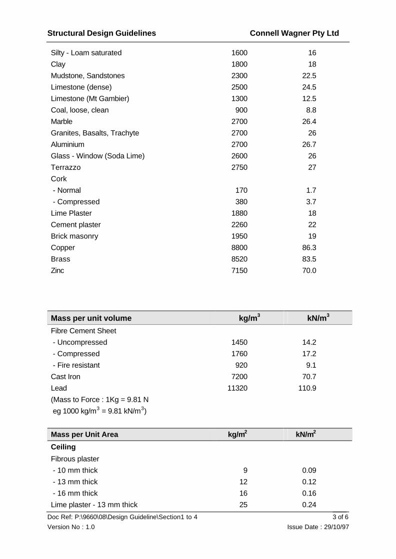
Densities and Mass of Materials Note that the values given for bulk materials may vary significantly, and further data should be obtained if any doubt exists.
Mass per unit volume kg/m3 kN/m3
Concrete (normal aggregate) 2400 24
Concrete (lightweight aggregate) 1900 19
For each 1% reinforcement add 60 0.6
Cement 1500 14.7
Steel 7850 77
Timber
- Hardwood (refer AS 1720 for actual 800-1200
8-12
- Softwood species densities) 400-600 4-6
Water 1000 9.8
Asphalt 2160 21.2
Sand - dry 1600 15.7
Structural Design Guidelines Connell Wagner Pty Ltd
Doc Ref: P:\9660\08\Design Guideline\Section1 to 4
Version No : 1.0 Issue Date : 29/10/97
3 of 6
Silty - Loam saturated 1600 16
Clay 1800 18
Mudstone, Sandstones 2300 22.5
Limestone (dense) 2500 24.5
Limestone (Mt Gambier) 1300 12.5
Coal, loose, clean 900 8.8
Marble 2700 26.4
Granites, Basalts, Trachyte 2700 26
Aluminium 2700 26.7
Glass - Window (Soda Lime) 2600 26
Terrazzo 2750 27
Cork
- Normal 170 1.7
- Compressed 380 3.7
Lime Plaster 1880 18
Cement plaster 2260 22
Brick masonry 1950 19
Copper 8800 86.3
Brass 8520 83.5
Zinc 7150 70.0
Mass per unit volume kg/m3 kN/m3
Fibre Cement Sheet
- Uncompressed 1450 14.2
- Compressed 1760 17.2
- Fire resistant 920 9.1
Cast Iron 7200 70.7
Lead 11320 110.9
(Mass to Force : 1Kg = 9.81 N
eg 1000 kg/m3 = 9.81 kN/m3)
Mass per Unit Area kg/m2 kN/m2
Ceiling
Fibrous plaster
- 10 mm thick 9 0.09
- 13 mm thick 12 0.12
- 16 mm thick 16 0.16
Lime plaster - 13 mm thick 25 0.24

Structural Design Guidelines Connell Wagner Pty Ltd
Doc Ref: P:\9660\08\Design Guideline\Section1 to 4
Version No : 1.0 Issue Date : 29/10/97
4 of 6
Gypsum plaster - 13 mm thick 13 0.13
Portland Cement plaster 30 0.29
Suspended metal lath and gypsum plaster
- No FRL 15 0.15
- FRL 1 hour 25 0.25
- FRL 2 hour 50 0.50
Suspended 13 mm plaster board 17 0.17
Fyrcheck
- 2 layer 13 mm 24 0.24
- 2 layer 16 mm 26 0.26
Stramit board 18 0.18
Metal Pan Ceilings (approximate) 10 0.10
Plaster acoustic tiles 15 0.15-0.25
Mineral fibre acoustic tiles 6 0.06
Floors
Asphalt - 25 mm thick 54 0.53
Cinder - Concrete filling 25 mm thick 45 0.43
Clay tiling, 13 mm thick 27 0.27
Carpet 10 0.10
Vinyl tile - 3 mm 7.0 0.07
Terrazzo paving - 16 mm thick 44 0.43
Mass per unit area kg/m² kN/m²
Roofs
Acrylic resin corrugated sheet 6 0.06
Cellulose fibre and asbestos cement, super 6 corrugated including lap and fastenings
16 0.16
Fibre and asbestos cement slates 22 0.22
Aluminium, corrugated including lap and fastenings
- 1.26 mm 5 0.05
- 1.00 mm 4 0.04
- 0.79 mm 3 0.03
- 0.63 mm 2 0.02
Bituminous felf (5 ply) and gravel 44 0.43
Steel, corrugated including lap and fastenings
- 1.00 mm 12 0.12
- 0.8 mm 10 0.10
- 0.6 mm 8 0.08

Structural Design Guidelines Connell Wagner Pty Ltd
Doc Ref: P:\9660\08\Design Guideline\Section1 to 4
Version No : 1.0 Issue Date : 29/10/97
5 of 6
- 0.5 mm 5 0.05
Custom orb (0.42 mm) 5 0.04
Tiles
- Terracotta (French pattern) 58 0.57
- Concrete 54 0.53
- Decramastic 7 0.07
- Slate Tiles
4.7 mm thick 34 0.34
9.5 mm thick 68 0.67
Walls
Brick Masonry, sold - clay per 100 mm of thickness
195 1.9
Concrete hollow block masonry standard aggregate
- 100 145 1.42
- 150 175 1.73
- 200 225 2.20
Concrete hollow block masonry lightweight aggregate
- 100 120 1.18
- 150 125 1.25
- 200 175 1.70
Concrete block masonry per 100 mm thickness
- Standard aggregate 220 2.2
- Lightweight aggregate 180 1.8
Co-efficient of thermal expansion mm/mm/10-6°C
Material
Aluminium 23.1
Brass 18.8
Brick Masonry 6.1
Cast Iron 10.6
Concrete 9.9
Copper 16.8
Glass 7.2
Granite 8.0
Lead 28.6
Limestone 7.6
Marble 8.1
Nickel 12.6

Structural Design Guidelines Connell Wagner Pty Ltd
Doc Ref: P:\9660\08\Design Guideline\Section1 to 4
Version No : 1.0 Issue Date : 29/10/97
6 of 6
Plaster 16.6
Sandstone 9.7
Slate 8.0
Steel 11.7
Zinc 31.1
Structural Design Guidelines Connell Wagner Pty Ltd
Doc Ref: P:\9660\08\Design Guideline\Section1 to 4
Version No : 1.0 Issue Date : 29/10/97
1 of 12
4. STRUCTURAL ANALYSIS
4.1. Introduction
The simple procedure for structural analysis should include the following steps:
• Inputs
• Model selection
• Structural analysis
• Verification of analysis
4.2. Codes
AS 4100 Steel Structures Code Amd 1993
AS 3600 Concrete Structures Code 1994
BS 5400 Part 2 App.C - Beam Vibrations
AS 1170 Parts 1 to 4 Australian Standard Loading Code
4.3. References
Steel Designer's Handbook Gorenc Tinyou Syam 6th ed. 1996
Steel Designer's Manual. Constrado 5th ed. 1992
Formulas for Stress and Strains. Roark and Young 6th ed. 1989
Reinforced Concrete Design Handbook. Reynolds 10th ed. 1988
4.4. Technical Notes
A95/4 Stability of buildings Feb 95 JW
A95/3 Structural Design Philosophy Jan 95 JW
M95/7 AS4100 1990 Section 11 Fatigue Feb 95 Bruce Wymond.
M95/5 Steel Mast Structure Fatigue Dynamic Analysis for along wind response Feb 95
JDB/BW
M91/M79/3 Warehouse design for wind March 1979 JHW
M91/M83/5 Plastic design of low rise steel portal frames Mar 83 WRG.
M91/M98/5 Hot dipped galvanised purlins Oct 78 JHW.
S96/1 Performance Brief for the design, detailing and documentation of post tensioned
floor structures by a post tensioning sub-contractor June 96 RWS
A95/7 Design of Columns using modified frame stiffness April 95 CS/NBT
Structural Design Guidelines Connell Wagner Pty Ltd
Doc Ref: P:\9660\08\Design Guideline\Section1 to 4
Version No : 1.0 Issue Date : 29/10/97
2 of 12
S94/1 Design of Pin Connections Aug 94 MB/JW
A95/2 Design of Masonry Jan 95 JW
M95/3 Hollow Core Plant design Feb 95 TL
4.5. Input
Inputs include items such as loads, geometry, support conditions, client requirements
(e.g. special deflection requirements), connection types, material properties, design
criteria (e.g. deflection limits) and codes which are to be followed.
Try to visualise or sketch out the structural details of the element you are to analyse
before starting any calculation or analysis. This process often points to other factors
which may influence your analysis, such as construction requirements, connection
types or other constraints.
4.5.1. Load Estimation
Your estimation of loads should be done carefully and be doubly checked as this is an
area where the most significant mistakes are made which have an impact on the final
design and costs. There is not always a need for your estimation to be exact but there
is always a need to know that you are correct.
You may be asked by the project design leader to estimate the design live loadings or
you may be given them. In any case, check that they are correct.
In estimating the load, contact will need to be made with the architect, client and the
services engineer. The architect is usually the first point of contact.
Questions to ask:
ie: What are the finishes?
Are the partitions to be masonry or non masonry?
Are there to be any high load areas such as storage or compactus?
Are there any plant areas ? What is the weight of the plant ?
Are there fire rating requirements which may dictate the type of
construction materials?
Refer also to Section 3 of Guidelines within this document.

Structural Design Guidelines Connell Wagner Pty Ltd
Doc Ref: P:\9660\08\Design Guideline\Section1 to 4
Version No : 1.0 Issue Date : 29/10/97
3 of 12
4.5.2. Load summary
The loading should be clearly indicated on Design Data sheets, approved by the
Project Design Leader and then given to all members of the structural design team.
These must appear at the front of the computations.
The live loads, wind and eqrthquake loads, plant loads and superimposed dead loads
should be shown on the drawings.
The client should be made aware of the design loadings used. A check should be
done to ensure that the loads are within the clients brief. This may only require
compliance to the Australian Standard Loading Code AS1170, Parts 1 to 4.
4.5.3. Design Criteria
The design criteria should be agreed with the Project Design Leader and should be
stated in your calculations. For larger projects this should take the form of a written
design philosophy setting out he structural form and loads.
Deflection Criteria
Deflection criteria are recommended in AS4100 and AS3600. A good summary of
some commonly accepted deflection criteria are provided in these Guidelines under
the appropriate material heading.
Vibration Criteria
• Deflection criteria for floor beams will normally give a suitable floor beam vibration
response. For long span floor beams or frames, limit the natural frequency of the
structure to greater than 8 Hz. Values less than this can be used if your model is
conservative, but this needs to be agreed with the project leader and client. Note
that floor systems that consist of beams supported by beams or beams
cantilevering from beam supports are more likely to have a lively vibration response
and should be designed carefully to avoid such occurrence.
Structural Design Guidelines Connell Wagner Pty Ltd
Doc Ref: P:\9660\08\Design Guideline\Section1 to 4
Version No : 1.0 Issue Date : 29/10/97
4 of 12
• For light weight composite floors refer Section 8 of these Guidelines.
4.6. Model Selection
Select an appropriate model making reasonable simplifications and assumptions. The
simple single span beam model is often the best solution. In considering the
complexity of the model consideration should be given to:
• the importance of the component in the overall design. A member that repeats
many times requires more accurate modelling than a one off element.
• the required accuracy of the results. There is no use in doing three slab analysis
when one is sufficient.
• constructability and cost of construction. For example consider carefully the
implications of adopting fixed end moment connections for steelwork.
4.7. Structural Analysis
Analysis methods depend on the complexity of the selected model. Analysis methods
that can be used include:
• Beam formulae
• Moment co-efficient
• Moment distribution
• Computer analysis
• Other design formula
Hand calculation of moments is now often replaced with a computer analysis which is
generally quicker. However, make yourself aware of design formulae which often give
sufficient information for design in less time than a computer analysis.
Note that a computer analysis results in a lot of output which needs time to be read,
printed and checked. The use of computer analysis must be agreed with the project
engineer so that your time can be well used.

Structural Design Guidelines Connell Wagner Pty Ltd
Doc Ref: P:\9660\08\Design Guideline\Section1 to 4
Version No : 1.0 Issue Date : 29/10/97
5 of 12
4.7.1. Analysis of Concrete Frames
Concrete frames and floor systems are typically analysed using SpaceGass or
ETABS in conjunction with RAPT. Building stability is typically analysed using
SpaceGass or ETABS (ie for Earthquake and Wind loadings). The design actions are
taken from this analysis to input in to RAPT for analysis and design of the floor
systems.
Care should be taken in using a "frame analysis" to design floor elements as the full
column moments may not be fully developed because of shrinkage cracking or
proposed construction methods. Increased floor deflections and midspan bending
moments may result. It may be appropriate to conservatively assume no moments
are developed into the columns for the floor. This assumption should be confirmed
with the project leader before analysis.
Refer AS3600 for guidelines on equivalent column stiffness; in particular, clause 7.7 of
AS 3600
4.7.2. Analysis of Steel Frames
Steel frames are typically analysed using SpaceGass for all load conditions. Steel
design may be done manually or within SpaceGass using the LIMSTEEL package or
design actions may be input into programmes such as MLPSTEEL. MLPSTEEL is a
steel design programme which can also be used to analyse single spans.
4.7.3. Analysis of Brickwork Panels
Refer tables in the Concrete Masonry Association of Australia Concrete Masonry
Buildings. A Practical Guide to Design, January 1992.
4.7.4. Computer Analysis
Our most frequently used analysis programs are Space Gass and RAPT. Other
structural analysis programs include ETABS, Strand and simple beam analysis
programs like Beam for Windows and MLPSTEEL.

Structural Design Guidelines Connell Wagner Pty Ltd
Doc Ref: P:\9660\08\Design Guideline\Section1 to 4
Version No : 1.0 Issue Date : 29/10/97
6 of 12
Most of our frame analysis is carried out on Space Gass. Space Gass has the
following special capabilities:
• non linear analysis - second order (p-delta) effects
• elastic buckling analysis - gives buckling load factors and effective lengths.
• dynamic analysis - gives mode shapes and their associated frequencies
• slaving modules
• response spectrum analysis - for refined earthquake analysis.
• cable elements - models catenary elements (zero bending stiffness)
• tension or compression only elements
• lime state.
ETABS is a similar analysis package which is set up specifically for multi-storey
buildings. ETABS is generally not as user-friendly as Space Gass but has the added
advantage of being able to model shear walls and also having a time-history analysis
for refined earthquake analysis.
Both Space Gass and ETABS are capable of carrying out non-linear analysis. Non-
linear analysis is generally adopted for steel and some concrete structures. Non-
linear analysis is critical for flexible frames with axial loads. It should be noted that for
a non-linear analysis to be valid any in-plane or out-of-plane restraints should be
properly modelled such that a realistic buckling load may be calculated.
RAPT is used to analyse and design floor systems. It is generally used to analyse
gravity loads only, however bending moment diagrams may be superimposed to allow
for lateral load cases. Note design actions from lateral loading must be calculated
elsewhere (ie. in a program like Space Gass or ETABS). For an accurate RAPT
deflection design, enter the actual reinforcement proposed. RAPT also has the facility
to limit steel stresses for liquid retaining concrete structure analysis.
Finite elements analysis is another, less common, type of analysis. Finite element
analysis is generally a higher tier analysis which is only adopted when the structure or
structural element cannot be adequately modelled by simple beam/column elements.
It is also sometimes used to calculate the internal actions and deflections of unusual
or non-uniform cross-sections. Before undertaking a FE analysis it is important input
Structural Design Guidelines Connell Wagner Pty Ltd
Doc Ref: P:\9660\08\Design Guideline\Section1 to 4
Version No : 1.0 Issue Date : 29/10/97
7 of 12
from those in the office obtained in such analysis techniques. Interpretation of results,
particularly for concrete structures, requires careful consideration.
The finite element package which is used in Connell Wagner is STRAND but
occasionally, when greater expertise or a more sophisticated analysis is required,
assistance may be sought outside Connell Wagner.
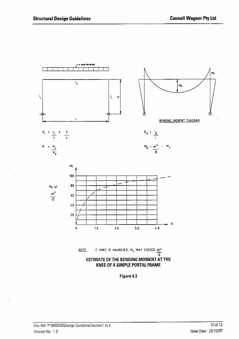
4.7.5. Formulae for Estimation of Beam and Portal Frame Shear, Moment and Deflection
Some common formulas are included in this manual. Refer Figures 4.1 to 4.5 in this
document. The references in Section 4.3 give a more comprehensive listing.
4.7.6. Formulae for Plates and Tanks
Refer References in Section 4.3.
4.7.7. Analysis of Irregular shaped concrete columns
RAPT and COLDES will give a design of irregular shapes columns however
slenderness effects must be manually estimated.
4.7.8. Analysis of Structures for Fatigue
Structures which we would more commonly require investigation of fatigue effects
include:
• Mast structures with fatigue induced by wind loading.
• Crane structures.
• Bridge structures.
4.7.9. Section Property Analysis
For core wall or irregular shaped section property analysis, THINSEC may be used.
4.8. Verification of Analysis
Analysis results should always be verified to the extent that the designer has an
appropriate level of confidence in the results. This verification would normally be done
by carrying out a more simplistic, independent analysis and comparing results.

Structural Design Guidelines Connell Wagner Pty Ltd
Doc Ref: P:\9660\08\Design Guideline\Section1 to 4
Version No : 1.0 Issue Date : 29/10/97
8 of 12
This verification process is the responsibility of the designer and should not be
confused with our QA design verification requirements.
Furthermore the model should be checked for its sensitivity to changes in input
variables. The variables which should be considered are those which the designer
has a degree of uncertainty about and may include the following:
• connection rigidity • support stiffness and/or settlements • loading variations including pattern loading • construction tolerances and/or techniques • material stiffness


Structural Design Guidelines Connell Wagner Pty Ltd
Doc Ref: P:\9660\08\Design Guideline\Section1 to 4
Version No : 1.0 Issue Date : 29/10/97
12 of 12
ESTIMATE OF THE DEFLECTION OF A SIMPLE PORTAL FRAME UNDER A SWAY LOADING
Figure 4.4

Structural Design Guidelines Connell Wagner Pty Ltd
Doc Ref: P:\9660\08\Design Guideline\Section1 to 4
Version No : 1.0 Issue Date : 29/10/97
13 of 12
ESTIMATE OF THE DEFLECTION OF A COLUMN WITH A BEAM SUBFRAME
Figure 4.5

Structural Design Guidelines Connell Wagner Pty Ltd
Doc Ref: P:\9660\08\Design Guideline\Section 5
Version No : 1.0 Issue Date : 29/10/97 1 of 51
5. REINFORCED AND PRESTRESSED CONCRETE
5.1. Introduction
The design of reinforced and prestressed concrete members in building structures
should be in accordance with the strength and servicability limit state requirements of
AS3600. The design is carried out using the design actions based on the loading
requirements of AS1170.1, AS1170.2, and AS1170.4 and those specific requirements
of the Client. The only exception to this rule is the design of water retaining structures
which is based on AS3735. The design principals for this code are stress limitation,
achievement of acceptable deflections, and minimisation of crack widths under
loadings.
5.2. References
• Warner Rangan and Hall ‘Reinforced Concrete’
• Warner and Faulker “Prestressed Concrete”
• TY Lin “Prestressed Concrete”
• RAPT Manual
• ‘Concrete Floor Systems’ and ‘Design Guide for Longspan Concrete Floors’
published by C&CA 1988 for guide to spans and framing
• CIRIA ‘Design of Deep Beams in Reinforced Concrete’
• Concrete Design Handbook published by the CIA
• ACI 318
• SAA ‘Guide to Concrete Repair’
5.3. Technical Notes Not completed.
5.4. Reinforced Concrete Floor Systems
5.4.1. General Reinforced concrete floor systems fall into many categories such as: • beam and slab
• flat slabs (slab with drop panels)
• flat plates (constant thickness slab)
• Banded slabs (slab with relatively wide but shallow beams having a width at least
Structural Design Guidelines Connell Wagner Pty Ltd
Doc Ref: P:\9660\08\Design Guideline\Section 5
Version No : 1.0 Issue Date : 29/10/97 2 of 51
twice their depth)
• A combination of any or all of the above
In recent times banded slabs have proven to be very popular because of superior
deflection control and relatively cheap construction costs.
5.4.2. Flexural Member Size Selection
The following criteria must be investigated and satisfied. As a general rule, as the
span increases for concrete members, the critical design parameter changes from
SHEAR to BENDING and then to DEFLECTION. Minimum material quantities in your
design do not necessarily lead to minimum total cost. This is due to high labour costs
in formwork and reinforcement placement. Furthermore, repetition on a job results in
reduction in the construction time and thus, total cost.
All members must meet the following criteria:
FIRE RESISTANCE - Fire Resistance requires minimum dimensions for members
and cover to reinforcement. Refer to the Building Code of Australia and to sections
5.5 and 5.6 AS 3600. Normally, it's the Architect’s responsibility to advise on project
specific fire-rating requirements.
DURABILITY - Durability requires minimum cover to reinforcement depending on
exposure conditions in accordance with section 4 of AS 3600.
SERVICEABILITY - Deflection Control Refer typical limitations in table 2.4.2 of AS
3600.
SHEAR -Cracking
One-way slabs Refer section 8.2 AS 3600
two-way slabs Refer section 9.2 of AS 3600
beams Refer section of 8.2 of AS3600.

Structural Design Guidelines Connell Wagner Pty Ltd
Doc Ref: P:\9660\08\Design Guideline\Section 5
Version No : 1.0 Issue Date : 29/10/97 3 of 51
BENDING - Typical reinforcement ratios are:
one-way slabs p = 0.003 - 0.0075
two way slabs p = 0.002 - 0.0060
beams p = 0.0075- 0.0180
footings p = 0.0020- 0.0025
AXIAL LOAD - Typical reinforcement ratios are:
walls p = 0.0015- 0.040
columns p = 0.005 - 0.0400
Generally a minor degree of crack control can be used as set out in clause 9.4.3.4 of
AS 3600. However, under certain circumstances, crack control will be more critical,
and special consideration should be given to reinforcement percentages and detailing.
These include:
1) those areas where concrete is to remain exposed
2) where brittle finishes are used on ceilings
3) water retaining structures.
The depth of a member is often selected to meet the deflection limitations. The
reinforcement content and width are then determined to meet bending and shear
requirements and constructability. The selection of a column dimension is influenced
by the axial load and moment. The influence of moment is greater at the top of a
structure and for exterior columns. Where shear is critical in the slab around a
column, it is preferable to provide a column head or increase the drop panel depth of a
flat slab. However, the simplicity of the flat plate type of formwork may overide this
criterion in some circumstances.
Also note that reinforcement is usually more expensive to carry load than concrete.
5.4.3. Typical Reinforcement Quantities
The following will assist Engineers in checking typical reinforcement quantities for their
projects.

Structural Design Guidelines Connell Wagner Pty Ltd
Doc Ref: P:\9660\08\Design Guideline\Section 5
Version No : 1.0 Issue Date : 29/10/97 4 of 51
M p x 7850 x C kg/m3 p average reinforcement ratio for gross cross-section,
allowing for top reinforcement. Note that reinforcement needs to be allowed for in two directions in slabs.
C allowance for splices, stirrups, ligatures and hooks
For Fy equal to 400 Mpa, the following allowances are appropriate:
Columns C 1.20 - 1.40
Beams C 1.10 - 1.30
Slabs C 1.05 - 1.10
Walls C 1.10 - 1.30
Range of Reinforcement Contents
These contents are indicative only and for each project they should be checked using
the above formula.
Member Type (kg/m3) Comment
Spread footings (on sand or clay)
(on rock)
40 - 60
150 - 300
Excluding column starter bars
Including column starter bars
Pile caps (single pile)
(multiple piles)
60 - 80
120 - 140
Strip footings 45 - 55
Rafts 30 - 50
Columns 150 - 250 Note that 1% = 150 kg/m³
Beams (RC overall depth) 150 - 230
One Way Slabs 70 - 90
Flat Slabs 90 - 110
Flat Plates 100 - 120
Band beam/slab (office)
(carpark)
110 - 135
90 - 115
Two Way Slabs 100 - 120

Structural Design Guidelines Connell Wagner Pty Ltd
Doc Ref: P:\9660\08\Design Guideline\Section 5
Version No : 1.0 Issue Date : 29/10/97 5 of 51
Waffle Slabs 100 - 120
Walls (minimum steel) 35 - 45
Walls (high-rise cores) 70 - 250
Walls (acting as column) Refer columns
Walls Retaining Earth 100 - 130
Cantilever Retaining Walls 100 -150
Slabs and banded slab (P/T) 30 (R/C) + 20 (P/T)
Where cost plans are prepared and tenders awarded on the basis of specified
reinforcement ratios, detailed analysis should be undertaken to confirm these rates
prior to issuing rates to the Q.S. These rates should be discussed and confirmed with
the Project Principal/Project Leader, and checked during final design. Also note that
these rates will need to be increased when earthquake detailing in accordance with
Appendix A of AS 3600 is required.
5.4.4. Deflection Limitations
Under serviceability loads, the deflection of reinforced concrete members must meet
two criteria:
• Total deflection less than span/250 and not to affect the appearance or
efficiency of the structure. A total deflection of span/250 will be aesthetically
unacceptable in many instances.
• Where concrete elements support masonry the incremental deflection should
not exceed span/500 unless closely spaced joints (at 6-8 m max) are provided.
Where the joints are not provided or the joint spacing is large, this limit should
be reduced to 1/1000.
The calculation of a deflection consists of two parts:
• an elastic or immediate deflection (short term)
• inelastic or creep deflection (long term)
AS 1170.1 sets out the various load combinations to be considered.

Structural Design Guidelines Connell Wagner Pty Ltd
Doc Ref: P:\9660\08\Design Guideline\Section 5
Version No : 1.0 Issue Date : 29/10/97 6 of 51
The calculated deflection is measured from a theoretical line diagram. The limit on
total deflection may not be adequate to prevent sagging of the member and ponding of
water. Accordingly, cambering of members may be required.
Longer span structures are particularly sensitive to long-term deflections and
vibrations.
An approximate guide is given below for span/overall depth ratio (L/D) for elements not
supporting brittle partitions or finishes. Note that these limits are appliable for live
loads in the range of 3 to 5kPa only.
One-Way Slabs L/D
Simply supported 25 - Continuous External span 28 Internal span 33
Cantilever 8 Note: For banded Slabs L is the clear dimension between the bands for internal
spans, or the centre of the edge support and face of band for end spans.
These span/depth ratios form the basis of concept and preliminary design and
RAPT should be used for final design.
Two-Way Slabs (with drop panels) L/D
Simply supported 30
Continuous External span 32 Internal span 36 without drops, multiply the above x 0.80
Beams L/D
Structural Design Guidelines Connell Wagner Pty Ltd
Doc Ref: P:\9660\08\Design Guideline\Section 5
Version No : 1.0 Issue Date : 29/10/97 7 of 51
Simply supported 14 Continuous External span 16
Internal span 20
Cantilever 6
Bands L/D
Simply supported 18
Continuous External span 20 Internal span 24
Cantilever 8
For brittle partitions and finishes, the above limits must be reduced by up to 25%.
RAPT should be used to accurately assess deflection. Be cautious about using
shallower sections without further investigation as serviceability is the most common
"failure" in structures.
Cantilever Deflection
Be wary of cantilevers as these are notorious for causing deflection problems.
Particular problems are return cantilevers (at corners), cantilevers which are heavily
loaded at the end by things such as planter boxes, and precast fascia elements,
cantilevers where the ends are fixed to deflection sensitive elements such as
brickworks or windows, and cantilevers where deflections are to be minimised and
preferably uniform for visual reasons.
It may be necessary to limit the total deflection for "longer" spans. In long span
structures, the FIP recommends that live load deflections not exceed 15mm.
Also note that when assessing deflections upper limits on the effective moment of
inertia should be used to account for 1) shrinkage cracking and 2) early age loading of
structure.
Experience suggests that for prestressed concrete members, Ieff = 0.7 Ig (max), and
for reinforced members, Ieff = 0.6 Ig (max).
Structural Design Guidelines Connell Wagner Pty Ltd
Doc Ref: P:\9660\08\Design Guideline\Section 5
Version No : 1.0 Issue Date : 29/10/97 8 of 51
5.4.5. Flat Slabs and Flat Plates
General
A flat plate, used in the context of a concrete slab, is a uniform thickness slab without
beams or drop panels. A flat slab is a uniform thickness slab without beams but with
drop panels around columns.
This form of construction has become less popular because of the limitation to spans
of about 8.5 m maximum due to their poor deflection performance. The design of flat
slabs (and flat plates) requires an understanding of their performance under 'normal
load' conditions such as office loads with light-weight partitions and abnormal load
conditions, such as masonry wall loads, heavy point loads, openings, set downs and
stair loads, etc.
Engineers must appreciate that, while deflection is just as important as strength in all
structural design, it is more so in the design of flat slabs and plates and special
attention must be given to the proportioning of the slab and drop panels before
proceeding with the final design. All preliminary drawings sent to the Architect must
show the immediate and long term deflections for the design proposed.
The design of flat slabs is covered in Section 7 of AS 3600. Engineers must fully
understand Section 7 of AS 3600 before proceeding with any design.
The computations for flat slabs should conform to the general procedures set out in
the following pages. If the Engineer has any sensible ideas for improvement in the
approach or set out, then discuss it with the Principal/Project Leader. Under no
circumstances are any changes to be implemented without the approval of the
Principal/Project Leader.
Based on past experience, consideration should be given to limiting reinforcement
stress under sustained loads to 170 MPa (or 300 MPa limit state) for column strip
reinforcement to assist in deflection control. This does not remove the necessity for
proper deflection calculations of critical spans, in particular, cantilevers and end
spans.
Flat slabs generally should be sensibly precambered (not overdone). Discuss with
Principal/Project Leader and remember to discuss with the Architect as it will affect

Structural Design Guidelines Connell Wagner Pty Ltd
Doc Ref: P:\9660\08\Design Guideline\Section 5
Version No : 1.0 Issue Date : 29/10/97 9 of 51
the finishes, etc.
Before you start your design, establish a grid reference system with the Architect so
that all bents (or frames) can be unambiguously identified.
Method of Design
Design of flat slabs can be carried out using either the Direct-Design Method (section
7.4 AS 3600) or the Equivalent Frame method as originally detailed in the Concrete
Code AS 1480 and modified in section 7.5 of AS 3600. Warner Rangan & Hall
‘Reinforced Concrete’ provides detailed discussion on this method, and Section 7 of
the "RAPT" manual also provides a very good overview of this method.
The Simplified Design Method may be used in appropriate situations provided the
designer is satisfied that the slab thickness is adequate for deflection control; that is,
by application of Section 9.3 of AS 3600.
The equivalent frame method involves the representation of the 3D slab system by a
series of 2D frames in two directions which are then analysed for the applied loads; ie
the full load in each direction.
The structure is considered to be made up of equivalent frames on column centre
lines taken longitudinally and transversely through the building.
The slab is divided into column and middle strips in accordance with AS 3600.
Analysis
Each equivalent frame shall be analysed in its entirety. Use judgement on similar
frames and discuss with the Project Leader as required.
5.4.6. Banded Slabs
General
A banded slab floor system consists of a series of parallel wide and shallow slab
bands on line with the columns with the floor slab spanning transversely between the

Structural Design Guidelines Connell Wagner Pty Ltd
Doc Ref: P:\9660\08\Design Guideline\Section 5
Version No : 1.0 Issue Date : 29/10/97 10 of 51
bands. The floor slab is designed as continuous haunched one-way slab, and the
bands are one-way shallow "beams" carrying all loads from the slab to the columns.
Slab bands are not treated as a beams, except for shear, subject to the provisions of
clause 8.2.5(c) AS 3600. AS a slab system, they are designed in accordance with
Section 7.5 of AS 3600. Concrete cover, fire ratings and reinforcement as required for
slabs in accordance with section 5, of AS 3600 are applicable to slab bands.
Particular attention must be given to the corners and the edges of the floor system
where two-way behaviour of slab may occur depending on the stiffness of edge
beams and columns.
The maximum span for reinforced concrete bands should not normally exceed 10.5m.
Above these spans bands should be prestressed. The slab band width should be
between band spacing/3 to band spacing/4 and where possible the width should be
based on the module of a standard sheet of formwork ply of 2.4m x 1.2m.
Vertical sides should be used to simplify formwork. Sloping sides are sometimes
used where bands are exposed to view or where the effective span of the slab needs
to be reduced. Typically for vertical sides, a slight slope is preferable to assist
formwork stripping.
Analysis of Vertical Loads
Analysis of banded slabs shall be carried out using the program "RAPT"
The floor slab is designed as a one-way slab continuous over the bands adopting a
knife edge support at the centre of the band (or column grid). The haunch effect
created by the slab band must be included in the analysis. A unit width of the slab is
considered in analysis using "RAPT". For structures with long end spans
consideration should be given to modelling the equivalent column stiffness. The
bands are designed to carry all the loads from the floor slab onto supporting columns
or walls.
Avoid pattern loading where possible - it is usually not required unless very heavy live
loads exists. (Refer Cl 7.6.4 of AS 3600.)

Structural Design Guidelines Connell Wagner Pty Ltd
Doc Ref: P:\9660\08\Design Guideline\Section 5
Version No : 1.0 Issue Date : 29/10/97 11 of 51
Flexural Reinforcement
Ultimate strength method shall be used in flexural design, earthquake design,
checking of shear resistance in slabs and design of shear reinforcement.
Generally only minimum reinforcement (1.0/fsy) is provided in slabs perpendicular to
the principal span of the slab, that is, in the secondary direction. This may result in
cracking parallel to the span of the slabs particularly at the column due to differential
shrinkage between the band beam and the slab. Check for restraint by walls at both
ends of a slab. Where the slab is exposed, an increase in the secondary
reinforcement should be considered.
Deflection
Deflection is as important in banded slabs as in flat slabs. Slab and slab bands must
be adequately proportioned and approved by the Principal/Project Leader before
sending designs to the Architect.
Precambers to slabs, based on deflection calculations shall be shown on the
drawings but use with care. Remember slabs are much more likely to deflect than
bands, as T beam action will occur in the bands between columns. "RAPT"
calculates deflections which have found to be generally reasonable but sometimes
conservative. Avoid excessive precambering, as cambers are very difficult to achieve
in 2-way systems, and it is suggested a maximum camber of approximately span/300.
Ensure the top surface is finished to a camber and not just the formwork. Also
consider the possibility that the camber will not come out.
Shear
Provisions for shear resistance of slabs shall be similar to those of flat slabs, and
shall comply with clause 8.2 of AS 3600. One-way shear in bands should also be
checked and two-way shear (punching shear) must be considered. Some shear
ligatures may be required for bands.
Reinforcement Detailing
Structural Design Guidelines Connell Wagner Pty Ltd
Doc Ref: P:\9660\08\Design Guideline\Section 5
Version No : 1.0 Issue Date : 29/10/97 12 of 51
Top and bottom slab reinforcement should be uniformly distributed across the full bent
width, except at columns where additional steel may be required for direct moment
transfer if columns included in the analysis. Remember, bottom reinforcement in the
end span MUST continue all the way to the extended edge support and at the first
support top reinforcement may need to be extended into the second span beyond the
1/4 point. It is a good idea to plot the moment profile for the end span and the first
internal span to check the correct curtailment of reinforcement for both the band and
slab. Bending moment diagrams and deflected shapes should always be plotted to
confirm modelling, and check adequacy of reinforcement curtailness.
It is good practice to provide top reinforcement a long column lines in the direction of
the span of the bands to control deflection induced cracking.
Ligatures, if required, should be open ligatures allowing for minimum cover
requirements to flexural steel. If earthquake design is necessary, then ligatures must
be closed.
Cold drawn wire and/or fabric ligatures should be considered, but plain wire ligatures
require much longer anchorage lengths. Do not use cold drawn wire for flexural
reinforcement in bands.
Distribution reinforcement to bands should be Y16 @ 1000 placed on top of the bottom
flexural reinforcement; ie second layer. Note that when shear reinforcement is
required, ties should sit under the main longitudinal reinforcement which reduces
effective depths.
Differential shrinkage between the large slab band and the slab may cause cracking
that will be aggravated in service if these cracks occur in the flexural tension zones. In
exposed slabs special attention must be paid to anchorage and lapping of distribution
steel, especially slab distribution steel parallel to the slab bands between column
centre-lines. The use of sloping sides to bands will reduce differential shrinkage
cracking.
The slab reinforcement must be the primary layers both top and bottom. This means
the top reinforcement to the bands will be in the secondary layer and bottom

Structural Design Guidelines Connell Wagner Pty Ltd
Doc Ref: P:\9660\08\Design Guideline\Section 5
Version No : 1.0 Issue Date : 29/10/97 13 of 51
reinforcement in the primary layer.
Where required, detail earthquake reinforcement in accordance with Appendix A of AS
3600 and AS 1170.4.
5.4.7. Precast Floor System
Scope
Precast floor systems are used on many projects because they can potentially offer:
1) Increased speed of construction where geometry is uniform.
2) Avoidance of propping leading to earlier installation of services.
3) Cost effectiveness compared with in-situ floor systems.
One potential drawback is lead times associated with procurement (shop drawing and
review, and should manufacture and construction).
There is a wide range of products including Humes prestressed hollow core planks,
ULTRA Floor and Transfloor. It is common to procure precast floor systems on a
Design and Construct basis.
Specific design information can be obtained from supplies catalogues.
5.4.8. Reinforced Concrete Beams
Scope
• This section covers the design of internal beams and external spandrel (edge)
beams in a reinforced concrete frame.
• Beam elements requiring special consideration must be discussed with the
responsible Project Principal or Project Leader will include:
i) Major transfer beams
ii) Core header beams - refer to "Core Wall" section

Structural Design Guidelines Connell Wagner Pty Ltd
Doc Ref: P:\9660\08\Design Guideline\Section 5
Version No : 1.0 Issue Date : 29/10/97 14 of 51
iii) Precast beams
General Design Parameters - To be Checked with the Project Principal/Project
Leader.
Analysis/Design Computer Programs
The analysis/design of beams can be carried out using RAPT but when spans are
repetitive, and pattern loading is not required, consider using moment coefficient from
section 7.2 AS 3600.
General Design Notes
i) For positive bending moments, design as a T- or L-beam provided the slab is cast
with the top of the beam.
ii) For deflection checks and frame analyses, analyse the beam as T- or L-beam to
realistically assess beam stiffness.
iii) Have the Project Leader confirm which beams are primary and which are
secondary (or tertiary).
(Note: Generally all reinforcement is primary except top reinforcement at beam-
to-beam connections.) Normally beam top steel is laid under top slab
reinforcement with stirrups in the sample plane as the slab top steel.
iv) Check with the Project Leader if there are any rebates or notches which reduce
effective beam dimensions, eg pocket for precast, corbels etc. Also, and
obviously, review the relevant architectural drawings.
v) For repetitive beam design, review reinforcement curtailment as this can
significantly reduce reinforcement costs, and where spans are uniform analyse
use the moment coefficients in section 7.2 of AS 3600 to save design time.
vi) Minimum reinforcement. Tensile reinforcement to comply with AS 3600. For
exposed beams, provide additional side face shrinkage reinforcement uniformly
distributed over beam depth to comply with AS 3600.

Structural Design Guidelines Connell Wagner Pty Ltd
Doc Ref: P:\9660\08\Design Guideline\Section 5
Version No : 1.0 Issue Date : 29/10/97 15 of 51
vii) Reinforcement detailing. Refer to Connell Wagner standard beam details and
schedules and the drafting manual. If the beam is part of a wind or earthquake
frame, special beam/column connection details are required to transfer wind and
earthquake forces. This usually requires continuous bottom reinforcement at the
column. Top reinforcement may be spread into the slab to reduce congestion.
Consider use of hard drawn wire ligatures for shear reinforcement.
viii) Torsion. In general, avoid designing beams for torsion. It is usually more
economic to resist the "out-of-balance" forces by the slabs in flexure than by the
beams in torsion. Discuss with the Project Leader as necessary.
a) Edge beam supporting banded slab
Refer to the "Banded Slab" section.
b) Edge beam supporting a flat slab is designed using the idealised frame method
(AS 3600). Redistribute at least 15% of the slab negative bending moment at
edge beam and increase the slab positive moment correspondingly. Max.
design torsion = Cracking torsional moment - see below.
ix) Ligature Detailing. Beams are usually detailed with closed ligatures. For
earthquake and torsion loads, ties must be closed.
Edge Beams Supporting Flat Slab
Torsion
Edge beams will be designed for:
a) 85% of the column strip moment
b) All loads directly on top of the beam, and
c) Torsional moments up to and including the cracking torsional moment.
Moments attributed to the beams greater than cracking torsional moment are to be
redistributed back into the adjacent span column strip.
Structural Design Guidelines Connell Wagner Pty Ltd
Doc Ref: P:\9660\08\Design Guideline\Section 5
Version No : 1.0 Issue Date : 29/10/97 16 of 51
Haunched Beams
Beams are sometimes haunched (deepened at ends where there is a fixity or
continuity) in order to achieve a reduced depth in the midspan regions. This may allow
ducts, etc, to pass under the beams without significantly increasing the floor to floor
height. However, the haunched section may require that the lights be positioned to
avoid beam locations, thereby reducing the flexibility of the tenancy layout.
Haunches may be either tapered or rectangular. Tapered haunches cause least
intrusion into the ceiling space but they are expensive to form because of varying depth
and every stirrup must be a different depth. However, they look better and are to be
preferred where beams are to be exposed. For the more normal case where beams
are hidden, rectangular haunches are preferable. Ends of beams can also be stiffened
by widening. This is not as efficient as a haunch but it is sometimes necessary. RAPT
can satisfactorily model haunches.
When designing a beam with a tapered haunch, account should be taken of the
upwards sloping compressive force at the bottom of the beam in the negative moment
region when considering shear reinforcement. Also, when the sloping and horizontal
bottom reinforcement meet, each must be provided with full anchorage. Do not bend
the bars and rely on local ties to resist the outwards component of the force tending to
straighten the bars.
Beam Penetrations
It is often difficult to accommodate horizontal penetrations through reinforced concrete
beams. However, when beams are fairly deep and narrow (rather than shallow and
wide) penetrations become a possibility.
Circular penetrations up to about one third of the overall depth can be easily
accommodated anywhere except within the depth of the beam from a support.
Rectangular penetrations of depth D/2 and width 1.5D can sometimes be
accommodated within the middle third of the span of a beam. The local area of the
beam is considered as a panel of a Vierendeel truss.
Because of the difficulty in getting sound concrete under the penetration formwork, it is

Structural Design Guidelines Connell Wagner Pty Ltd
Doc Ref: P:\9660\08\Design Guideline\Section 5
Version No : 1.0 Issue Date : 29/10/97 17 of 51
unwise to rely on this “bottom flange” to resist shear. Rather, drop the penetration as
far as cover to the bottom bars will allow, and design the resulting deeper top flange for
all of the shear using a strut and tie approach.
If the penetration must be kept as high as possible, then distribute the shear in
proportion to the areas of beam remaining and specify that the concrete be placed from
one end of the penetration only until the volume is completely filled as evidenced by
concrete flowing from the full depth at the other end. Strict supervision will be required
to ensure this happens.
Notched Beams
Ducts can be accommodated within the beam depth by notching a continuous beam
near midspan or a simply supported beam at the end. In the case of the latter, shear
becomes a major design consideration and may require a widening of the beam (a
thickening of the slab).
5.5. Prestressed Concrete Floor System
5.5.1. General
Prestressed concrete is to be designed in accordance with AS 3600.
• Typical flooring systems include flat slabs, flat plates, banded slabs and beams.
Generally prestressed concrete is used:
• for longer spans where reinforced concrete structure would deflect excessively; ie
9 m or more
• where dimensions of concrete must be minimised (depth)
• where control of deflection is essential
• where waterproofing is necessary although we should never infer that post-
tensioned structures will be waterproof

Structural Design Guidelines Connell Wagner Pty Ltd
Doc Ref: P:\9660\08\Design Guideline\Section 5
Version No : 1.0 Issue Date : 29/10/97 18 of 51
• where shear is a problem
• where costing analyses indicate that prestressing is beneficial.
Concrete can be either pre-tensioned or post-tensioned, and either partially or fully
prestressed.
Prestressing can include cables, bars, ground anchors etc. The most economical
solution is normally to have the same level of prestress in each span.
5.5.2. Design Check List
• Establish fire resistance ratings and covers.
• Ensure preliminary design has fully assessed all design parameters including
loads, degree of continuity. Check special heavily loaded areas, as these are not
as easy to handle as for RC design.
• Ensure adequate space is provided for anchorages, especially with two-way
systems and at columns and RC beams.
• Check shortening of floor and effect on walls and columns.
• Check end spans.
• Check position of holes for ducts, risers, as again, the position of these are not as
flexible as RC design.
• Carefully consider location of construction joints etc and distances between them.
For post-tensioned floors, we effectively set the construction sequence by the
location of the C.J.s. This need careful consideration and preferably input from
the builder.
• Avoid anchorages at edges of slabs and beams where this may involve
scaffolding for stressing.
• Avoid layouts requiring woven tenders.

Structural Design Guidelines Connell Wagner Pty Ltd
Doc Ref: P:\9660\08\Design Guideline\Section 5
Version No : 1.0 Issue Date : 29/10/97 19 of 51
• Can it be built?
5.5.3. Analysis
Linear elastic analysis is normally used. Analysis is generally carried out using the
"load balancing" methods.
Both the VSL and Austress design manuals provide detailed methods of design by
hand, and the previous section sets out a step-by-step method of design.
The computer program "RAPT" is to be normally used for detailed design of
prestressed members.
5.5.4. Deflection Limitations
An approximate guide is given below for span/overall depth ratios for elements not
supporting brittle partitions or finishes.
One-Way Slabs L/D
Simply Supported 30
Continuous External Span 32
Internal Span 40
Cantilever 10
Note: For banded Slabs L is the clear dimension between the bands for internal spans,
or the centre of the edge support and face of band for end spans. These
span/depth ratios form the basis of concept and preliminary design and RAPT
should be used for final design.

Structural Design Guidelines Connell Wagner Pty Ltd
Doc Ref: P:\9660\08\Design Guideline\Section 5
Version No : 1.0 Issue Date : 29/10/97 20 of 51
Two-Way Slabs (with drop panels) L/D
Simply Supported 32
Continuous - External Span 40
Internal Span 45
Beams L/D
Simply Supported 18
Continuous External Span 20
Internal Span 22
Cantilever 10
Banded Slab L/D
Simply Supported 24
Continuous External Span 26
Internal Span 28
Cantilever 12
• The most economical design system will occur if the end span is 80% of the
internal spans with the same effective depths, internal spans are equal, and
cantilevers are 30% of adjacent spans.
• The above ratios provide a quick preliminary size. This size must always be
checked before acceptance by the Designer.
• Sections being tensioned should be limited to 30-40 metres.
• The minimum slab thickness, where tendons are in the slab, is 150 mm to allow for
cables and dead and live end anchorages.

Structural Design Guidelines Connell Wagner Pty Ltd
Doc Ref: P:\9660\08\Design Guideline\Section 5
Version No : 1.0 Issue Date : 29/10/97 21 of 51
For brittle partitions on finishes the above limits must be reduced by up to 20%. The
exact span/depth ratio's must be calculated to meet the serviceability requirements of
AS 3600.
The most common problems with prestressed members is the use of excessive
stressing forces. Wherever possible, use partially prestressed design.
5.5.5. Prestressing Tendons and Details
The two usual strand sizes are 12.7 mm and 15.2 mm. The most common size is
12.7 mm. The strand used is usually low relaxation, stress relieved, super grade.
Only use one size strand on any project except in special circumstances.
The 12.7 mm strand has an area of 100 mm2 and a minimum strand breaking load of
184 KN. In slabs, the strands are usually grouped in galvanised flat ducts to create
tendons. The duct is fully pressure grouted after the strands have been fully
tensioned.
Ducts are:
70 mm wide x 19 mm for up to 5 strands
90 mm wide x 19 mm - 6 strands (not normally used)
For beams, round ducts from 60 mm to 140 mm in diameter are usually used.
However, 4 or 5 strand ducts are often used in beams in buildings. A friction factor of
0.2 is normally used for oval duct.
The duct should have a minimum cover of 25 mm with covers checked for durability
and fire rating as required.
Tendons are usually draped in a parabola in the case of a uniformly distributed load to
give uniform load balance.
Prestress losses must be calculated and include:
• immediate losses
• deferred losses

Structural Design Guidelines Connell Wagner Pty Ltd
Doc Ref: P:\9660\08\Design Guideline\Section 5
Version No : 1.0 Issue Date : 29/10/97 22 of 51
• frictional losses
• draw-in losses
• frame-resistance losses (ie losses due to restraint by the structure being
stressed).
Refer to written information from the various manufacturers such as VSL.
5.5.6. Flat Slab Design
Slabs shall be designed using load balancing. If the weight of the Concrete is
balanced, the long term deflections can be expected to be minimised. The designer
must check stresses at:
• transfer
• at full load
Tendons are usually draped in a parabolic shape to follow the same shape as the
bending moment diagram.
Tendons must end at the centroid of a cantilever or simply supported slab end;
otherwise, large secondary forces can occur.
The prestress level is generally in the range of 1.5-3.5 MPa working stress.
Losses in prestressing forces due to the following must be allowed:
• friction
• elastic shortening of concrete
• creep and shrinkage of concrete
Where draped tendons are greater than 20 m, they should be stressed from both
ends. The position of anchors and stressing ends need careful consideration to avoid
expensive scaffold for stressing access.
Details of connections to columns and RC walls needs careful consideration to avoid
cracking or restraint.
Structural Design Guidelines Connell Wagner Pty Ltd
Doc Ref: P:\9660\08\Design Guideline\Section 5
Version No : 1.0 Issue Date : 29/10/97 23 of 51
Slabs are normally stressed to 25% at 1-3 days to control slab shrinkage cracking with
final stressing at 7 days.
Design of slabs is normally carried out using the computer program "RAPT".
5.5.7. Banded Slab Design
The design of banded slabs is similar to slabs. They shall be designed using the
computer program "RAPT".
"RAPT" is a sophisticated program and should only be used by Designers who have a
reasonable "feel" for post-tensioned design and who have carried out some design by
hand.
5.5.8. Earthquake Detailing
Tendons should not be anchored or develop their strength in beam/columns/joints
where high moments develop under earthquake loads. In addition, ducts should be
corrugated. Refer to Appendix A of AS 3600 for specific requirements.
5.6. Reinforced Concrete Columns
5.6.1. Scope
This section covers the design of reinforced concrete columns in accordance with
AS 3600.
5.6.2. Load Rundowns
• Use a standard proforma sheet or a spreadsheet.
• The loads to be used must be obtained from the loading sheets in Section 3 of this
manual and are to be in accordance with AS 1170 Part 1, Dead and Live Loading
and Load Combinations.

Structural Design Guidelines Connell Wagner Pty Ltd
Doc Ref: P:\9660\08\Design Guideline\Section 5
Version No : 1.0 Issue Date : 29/10/97 24 of 51
• Typically apply live load reductions where possible in accordance with AS 1170
Part 1. Note that live load reductions to be applied are calculated on the cumulative
area of the floor or floors contributing load to the column above the level
considered. (Note: Live load reductions are not normally applied to individual
beams and slabs.)
• If loads for a particular area on a floor are not in the loading sheets, refer to the
Project Leader for direction.
• Where they have not been calculates, apply moment shear (elastic reaction)
factors to column loads in accordance with the following diagram. It is preferable to
calculate moment shears from actual bent runs. P is the total load on a column for
the simple contributing area indicated.
• Rundowns are calculated using a simple area basis proportioning the loads to each
vertical element by taking half the distance in each direction to the adjacent vertical
element. The areas should be marked up on the structural concrete profile plans
which are then scaled to determine the plan dimensions of each tributary area.
(Assumes equal spans between all columns).
• Also incorporate "fast track" load allowance where appropriate. Refer to the Project
Leader for these allowances.

Structural Design Guidelines Connell Wagner Pty Ltd
Doc Ref: P:\9660\08\Design Guideline\Section 5
Version No : 1.0 Issue Date : 29/10/97 25 of 51
5.6.3. Design Loads
List the loads for various elements supported by the column from each floor and roof
using the appropriate floor and roof areas. The unit loads for roof, floors, stairs and
walls (calculate the average load per metre length including where openings occur)
must be listed on first sheets of computations in the loading sections.
Include live load reduction where applicable, in accordance with AS 1170 Part 1.
Priior to completing the rundown of the loads for a column, check the Architect's and
other Consultants and Disciplines drawings to ensure that all loads have are included.
The following list covers the majority (but not all) of loads that can be expected in
column designs for multi-storey structures.
Roof (including finishes)
Floor (including finishes)
Partitions - light-weight, terrazzo, etc.
External walls - precast, curtain wall etc.
Internal masonry walls
Beams framing into column
Precast concrete wall units
Fascias and sunhoods
Lift machinery
Air Conditioning Equipment
Stairs
Heavy load area
Special equipment; ie water tank, generator etc.
Ceilings
Heavy architectural bulkheads.
Include in the column computations for moments due to:
a) The floor system (refer to the computations for the frames and loads).
b) Minimum Bending Moments as required by AS 3600.
c) Wind

Structural Design Guidelines Connell Wagner Pty Ltd
Doc Ref: P:\9660\08\Design Guideline\Section 5
Version No : 1.0 Issue Date : 29/10/97 26 of 51
d) Earthquake
e) Any other lateral loads.
In column design, it is important to correctly estimate the applied moments particularly
at the top of the building where column dimensions can be small and the bending
moments are high with low axial loads.
5.6.4. Reinforcement
Avoid high % of reinforcing steel as it is an uneconomical way of carrying axial loads,
which are most economically supported by maximising concrete strength or column
loads. Where tension controls, make sure the lap lengths are based on a tension
splice.
Check the curtailment of column bars at the top of columns and at changes in the size
of columns. Check that column and beam bars will fit at each intersection.
5.6.5. Concrete Strengths
The minimum concrete strength in any column should be 25 MPa. The maximum
strength currently allowed by AS 3600 is 50 Mpa. Considerable research is being
undertaken to investigate detailing requirements for higher strengths.
Connell Wagner has used strengths up to 80 Mpa on some projects. When using
higher strength concrete, refer to latest internal technical notes on this subject.
Economic studies have shown that the cheapest columns will almost always involve
the highest strength concrete and 1% reinforcement. On major projects always
determine what is the maximum strength available locally. On most projects, 60 Mpa
concrete can be used to keep column dimensions to a minimum, and achieve
economical results.

Structural Design Guidelines Connell Wagner Pty Ltd
Doc Ref: P:\9660\08\Design Guideline\Section 5
Version No : 1.0 Issue Date : 29/10/97 27 of 51
5.6.6. Bending Moments
Two cases of bending of columns will occur. These are:-
a) Uniaxial Bending Square (Rectangular and Circular)
b) Biaxial Bending (Rectangular) and Square
Note: The design moment in the columns is the moment at the top or bottom face of
the slab or beam and not the centre line of the slab. Use using second order
analysis in accordance with section 7 of AS 3600 to directly generate the
design actions, in both sway and braced frames. Also note that section 7
requires reduced stiffness for each structural elements. For prestressed
beam element use Ieff as calculated by RAFT.
5.6.7. Slenderness Ratios
Evaluate the slenderness ratio to determine if columns are short or slender, but when
using second order analysis only calculate d b based on actual member length.
5.6.8. Fire Resistance and Cover
Check covers for external columns or other special conditions, such as downpipes,
sewer and vent stacks included in columns, etc.
Check fire resistance of columns in accordance with sections 5.5 and 5.6 of AS 3600.
The actual fire ratings (resistance) for members is normally based on the Building
Code of Australia and should be provided by the Architect.
5.6.9. General Design Notes
• Group columns logically into a series of typical columns in order to minimise
computer time and analysis of every column.
• Use concrete strengths as follows: 60 Mpa, 50 MPa, 40 MPa, 32 MPa, 25 Mpa but
preference should be given to maximum strength to minimise reinforcement.

Structural Design Guidelines Connell Wagner Pty Ltd
Doc Ref: P:\9660\08\Design Guideline\Section 5
Version No : 1.0 Issue Date : 29/10/97 28 of 51
• Generally aim for about 1% maximum reinforcement content to achieve an
economical solutions. Absolute maximum 4% for few columns at the lower levels.
• Maintain column concrete strength the same on each floor level where possible.
This avoids the construction complications of placing different concrete grades.
• Prior to design ensure column sizes are agreed by Architect, especially where they
go through car parks and other architecturally sensitive areas.
• Check fire ratings of all columns, especially thinner "blade" columns, using section
5.6 of AS 3600.
• Minimum width of blade columns to be 300 mm if 2 hour fire resistance is required.
• Draw reinforcement intersection diagrams for critical beam/column and
beam/beam/column junctions. Optimise the position of the beam relative to the
column.
• Carefully check bar development/splice requirements are met:
I. at intersections between columns that change shape either side of a floor;
II. towards the tops of buildings where the axial stress is lower; and
III. in sway frames.
• Ensure "transmission of axial force" requirements of section 10.8 AS 3600 are met
for edge columns of floor structure or where columns sit on unconfined walls of
lower strength. Consider providing additional dowel bars rather than introducing
"blobs" of concrete of a higher strength.
• Ensure ties are detailed in accordance with clause 8.2.12 of AS 3600. Where bars
are cranked it is necessary to provide additional ties to resist the lateral bursting
forces. Ties must continue through the floor beam sections to maintain lateral
restraint to column bars.
Structural Design Guidelines Connell Wagner Pty Ltd
Doc Ref: P:\9660\08\Design Guideline\Section 5
Version No : 1.0 Issue Date : 29/10/97 29 of 51
• Ensure ties meet the requirements of Appendix A of AS 3600.
• Consider 2 storey lifts for cages where possible.
• Design columns using RAPT or Coldes. Recent “bench testing” of various design
methods by Brisbane office has proven that RAPT is the best design tool. RAPT
can also take account of internal voids, and handle unusual shapes.
5.6.10.Preliminary Design
A short column can be approximately sized using A = P*/(0.5 Fc'). The approximation
is derived on the basis the reinforcement percentage will be around 2 percent.
To control the column size it is most cost effective to use high strength concrete than
large percentages of reinforcement (50 or even 60 Mpa). As the load diminishes
reduce the reinforcement first, then the concrete strength and finally the column size.
The mass of reinforcement used for preliminary costing of the structure is shown
below. It can be seen that the relationship approximates to the easily remembered
following sequence.
1% longit reinf. 150 kg/m³
2% 250
3% 350
etc.
These rates must always be confirmed by analysis before issuing of Tender
documentation. These rates may increase when earthquake detailing is required.
5.6.11.Column Ties
Always arrange reinforcement so that there is a large space free of any obstruction to
the placing and compacting of concrete. If the ties become excessively congested,
consider bundling the longitudinal reinforcement.
5.6.12.Column Starter Bars

Structural Design Guidelines Connell Wagner Pty Ltd
Doc Ref: P:\9660\08\Design Guideline\Section 5
Version No : 1.0 Issue Date : 29/10/97 30 of 51
Starter bars out of footings should be embedded in the footing a distance equal to the
compression development length, 20db, if the footing is able to develop column fixity
and the column reinforcement goes into tension, the tension development length must
be used.
Only straight lengths of bars transfer compression via bond - the length of the bar
beyond a 90° bend has been shown by strain gauging to be unstressed, so there is
nothing to be gained by extending cogs beyond the length needed to support the
starters on the footing reinforcement. However there is no need to make all footings
over 20db thick as, besides transferring load by bond, the bars transfer load by bearing
around the underside of the bend.
5.6.13.Column Size Reductions
It is often appropriate to reduce the column size as the load diminishes. (However, as
changes to formwork cause cost increases, the need to reduce the size should be
seriously considered). Reinforcement at reductions may be cranked across at 1 in 6
where the reduction does not exceed 75mm. For greater reductions, separate starter
bars must be provided.
Remember that unequal steps in the faces of a column create loading eccentricity
which must be considered in design, either by treating the movement in the column or
by resolving the movement using propping forces in the floor.
5.6.14.Top Termination of Column Reinforcement
Because columns attract bending moments, column reinforcement should be
anchored into the slab or beam sufficiently to develop its full tensile strength, i.e. for its
full development length, Lsy. Always carefully draw out these details to prove that full
anchorage can be achieved.
5.6.15.Bundles Bars
For large, heavily reinforced columns, it is often advantageous to use bundled bars.
Usually compression will govern so that simple splice sleeves such as G-Locs can be
used. Bundling of bars reduces the number of ties required but Y12 ties should be
used.

Structural Design Guidelines Connell Wagner Pty Ltd
Doc Ref: P:\9660\08\Design Guideline\Section 5
Version No : 1.0 Issue Date : 29/10/97 31 of 51
It is often possible to use 2 storey high bars when bundled. This halves the number of
splices and facilitates the staggering of splices in bundles of 4 bars.
Note: Never use bundled bars unnecessarily as they can significantly slow up
construction. The perimeter beams and columns are usually the critical elements
during construction of multi-storey buildings. Usually speed of construction is
increased by prefabricating column reinforcement but this cannot be done when bars
are bundled; each bar has to be individually positioned.
5.6.16.Column Splices
The normal reinforcement splice is a lapped compression splice.
Bars usually cranked at their top as this will often leave the inwards bend well confined
by concrete and it may also facilitate the passage of the top reinforcement of
intersecting beams.
However, sometimes the crank ban be beneficially located at the bottom of the bars to
suit the meshing of beam and column steel.
Column design is governed by tension or compression in the reinforcement,
depending on where the design lies on the interaction diagram. Laps should be
proportioned accordingly.
5.6.17.Mechanical Tension Splices
Swaged Splices
CCL Alpha splices are sometimes used. These are crushed on to deformed bars
using a swaging jack. The splices come in two types (1) fully swaged and (2) swaged
and threaded. The latter is used when it is necessary to end the couples flush (e.g.
against the inner face of formwork) or when it is impossible to insert the jack because
of the proximity of other bars.
These splices are bulky (so leave enough space) and expensive (so consider
alternatives before specifying).

Structural Design Guidelines Connell Wagner Pty Ltd
Doc Ref: P:\9660\08\Design Guideline\Section 5
Version No : 1.0 Issue Date : 29/10/97 32 of 51
Screwed Couplers
Leonton manufacture screwed tension couples.
A comprehensive range of coupling devices, all utilising a tapered thread are available.
The range includes couplers to enable bars to be inserted between cast-in couplers
nuts to anchor bars in concrete or behind a steel plate, plugged anchors cast into
concrete for future bar extensions and of course, standard bar couplers (which are
less bulky than Alpha splices).
Epoxy Grouted Sleeves
Epoxy grouted sleeves are available from A H Reid Pty Ltd. These rely on mechanical
interlock via the epoxy grout between the deformed bar and deformations inside the
sleeve. They are often used by the precast industry in the USA as they will tolerate a
small amount of bar misalignment.
Epoxy grouted sleeves are at least as expensive as screwed CCL Alpha Splices.
5.6.18.Column Axial Shortening
All compression members shorten under axial load but concrete members exhibit
more shortening than steel members because of shrinkage and creep. This factor
must be including in the design of facades of multi-storey buildings and in the detailing
of lift guide rails in the services core. It is also a factor for serious investigation where
a highly stressed column is adjacent to a much lower stressed column or wall.
It is not desirable to locate internal columns only a corridor width away from concrete
core walls given the difference in shortening expected on these 2 elements.
Similarly, investigation is necessary when a change in the plan size of the floor of a tall
building results in adjacent columns carrying vastly different axial stresses. In such a
case, the axial stresses of the 2 columns may be able to be evened up by a transfer
Structural Design Guidelines Connell Wagner Pty Ltd
Doc Ref: P:\9660\08\Design Guideline\Section 5
Version No : 1.0 Issue Date : 29/10/97 33 of 51
beam. Alternatively, prestressing the lightly loaded column so it behaves as a heavily
loaded column may be appropriate.
5.6.19.High Strength Concrete
There may be occasions when it s necessary to use significantly stronger concrete in
isolated columns. When this occurs, it must be emphasised on the drawings over
and above the normal means of specifying the concrete strength.
High strength concrete requires that a number of additional requirements be
addressed as follows:-
1. Ability to Obtain the Strength
Not all localities produce aggregate able to achieve concrete strengths in excess of
about 60 MPa so check with the local concrete suppliers.
2. Continuity of Strength Through Floors
This will not be a problem where floors are of steel beams supporting a steel deck
and concrete slab. However, a full concrete floor where the concrete strength will
usually be 25 or 32 MPa, will require that the same high strength concrete be
placed in the column area during the floor pour. Such concrete should be colour
tinted to allow easy recognition. It should not be placed using the concrete pump
being used for the lower strength concrete. Specify detailing and strength
assessment requirements are set out in Section 10.8 of AS 3600. Alternatively
additional dowel bars can be added to achieve the necessary strength.
5.6.20.Bending Moments in Columns
Columns derive bending moments from lateral forces on the building and from
unbalanced bending moments in floor slabs or beams framing into the column.
Where such moments are difficult to accommodate, e.g. for small interior columns in
a low rise structure or for the external columns of a small building, the moments can
be minimised by taking full advantage of the allowable redistribution of moments in the
floor. Also, a critical review of the member stiffness (what will be cracked and what
will be uncracked) may result in a different set of moments.

Structural Design Guidelines Connell Wagner Pty Ltd
Doc Ref: P:\9660\08\Design Guideline\Section 5
Version No : 1.0 Issue Date : 29/10/97 34 of 51
Some columns, particularly corner columns, are always subjected to biaxial bending.
When the bending moments are significant about both axes it is necessary to design
the column for the biaxial effects.
In tall, flexible buildings, the sway creates additional moments due to the P-delta effect.
The second order moments may be up to 10% of the first order moments and should
not be overlooked.
5.6.21.Concrete Placing, Stripping and Curing
Concrete should be placed in a manner which avoids segregation. With widespread
use of pumping and with adequate clear space between column ties, segregation is
seldom a problem.
Concrete should always be placed in column forms and left to set before concrete is
poured for the floor. (A delay of an hour or two would suffice). The reason is that is
both column and floor are poured concurrently, a crack will often form through the
column just below the soffit of the floor due to settlement of the column concrete and
arching of the slab or beam concrete across the column.
Columns may be stripped as soon as the concrete is hard enough - usually after
about 24 hours. With 25 MPa concrete it is advisable to provide for additional curing
by wrapping the column with polythene but for stronger concrete this is unnecessary.
(High strength concrete is more dense and the small voids are rapidly sealed,
preventing the loss of water from the interior of the mass).
Structural Design Guidelines Connell Wagner Pty Ltd
Doc Ref: P:\9660\08\Design Guideline\Section 5
Version No : 1.0 Issue Date : 29/10/97 35 of 51
5.7. Reinforced Concrete Walls
5.7.1. Design approach
Refer Chapter 7 of the Reinforced Concrete Design Handbook.
5.7.2. Walls - Low to Medium Rise
Generally use Section 11 of AS 3600. This code is satisfactory for the majority of wall
designs in low rise buildings.
5.7.3. Core Walls - High Rise (greater than 20 Storeys)
Consisting of a number of interlinked walls of various lengths, thicknesses, stiffnesses
etc, and special provisions have been developed for these.
These provisions recognise the ability of core elements to plastically redistribute loads,
under ultimate conditions, enabling the total load capacity of core systems to be
obtained by the summation of individual core wall capacities.
There are some important restrictions:
I. Wall slenderness kL < 20
D
II. Two layers of reinforcement are required
III. Serviceability criteria
In solid walls subjected to vertical loads, stresses are forced to distribute evenly when
lateral restraints such as floors are present, irrespective of core wall layout.
Finite Element studies have shown this force distribution occurs at approximately 45°
or less (ie, rapidly enough to assume constant stress in tall buildings).

Structural Design Guidelines Connell Wagner Pty Ltd
Doc Ref: P:\9660\08\Design Guideline\Section 5
Version No : 1.0 Issue Date : 29/10/97 36 of 51
These findings consider Strain Compatibility, which implies uniform shortening and
thus reasonably constant element stress. This uniform stress will act at serviceability
conditions and will continue to do so until plastic redistribution (noted above) is
required at ultimate conditions.
5.7.4. Influence of Creep Relaxation
Large openings in walls and header beams significantly affect the stress distribution in
the core walls.
Depending on the stiffness of the header beam, load will be shared between adjacent
core elements.
However, over the life of the building the header beams will undergo creep relaxation
and will no longer transfer all of this stress.
5.7.5. Basement Retaining Walls
Loading
These walls are usually restrained against lateral movement by floor slabs, struts or
ground anchors etc. so that 'active' pressure conditions are not likely to be obtained.
The Soil Pressure diagram is not the normal triangular form but usually trapezoidal or
modified triangular shape.
The shape and design values for this diagram should be provided by the Geotechnical
Engineering Consultant. Generally maximum pressures are of the form
P max = AH + Bq
Where, A is a factor usually between 4 and 8
H is the height of the wall
B is a factor usually between 0.3 and 0.5
q is the surcharge pressure

Structural Design Guidelines Connell Wagner Pty Ltd
Doc Ref: P:\9660\08\Design Guideline\Section 5
Version No : 1.0 Issue Date : 29/10/97 37 of 51
Walls
Walls should be classified as either temporary or permanent.
Temporary Walls:
Temporary walls are those that are constructed to enable excavation to proceed prior
to the construction of a permanent wall immediately in front of them. The advantages
of using this type of wall are:
a) The wall can be placed outside the site boundary subject to approval of the
Council. (They will require later removal down to specified levels. Check with
the Council.)
b) Temporary ground anchors can be used - these anchors require no secondary
grouting and are cheaper than permanent ground anchors.
Note: Ungrouted stressed anchors should not be left in the ground, however
as they represent a hazard to future excavation.
c) Can take advantage of increased allowable steel and concrete stresses for the
temporary condition.
d) Can possibly take advantage of reduced pressure diagram for temporary
condition.
Temporary walls often take the form of double steel channel or I beam soldiers
vertically with infill insitu concrete panels or timber sleepers spanning horizontally.
The permanent wall in front of this is constructed either as reinforced or precast
concrete.
Permanent Walls:

Structural Design Guidelines Connell Wagner Pty Ltd
Doc Ref: P:\9660\08\Design Guideline\Section 5
Version No : 1.0 Issue Date : 29/10/97 38 of 51
Permanent walls are constructed to resist the permanently applied loads (including
water pressures) unless a proven system of drainage is provided. Walls normally
span vertically between the permanent structure at floor levels or sometimes where
spans are large or pressures high, permanent ground anchors will be required in lieu
of structure.
The main advantages of using a permanent wall in lieu of a temporary wall is that the
final wall can be completed in one operation. Typical walls of this nature are:
i) insitu bored pile soldiers with shotcrete infill arches (Connell Wagner Arch.)
ii) precast concrete soldiers with shotcrete in fill panels
iii) precast panel walls
All the above walls utilise temporary ground anchors or props in the temporary
(construction) condition.
All permanent walls must be wholly within the site boundaries. In the case of (i) and
(ii) above, considerable basement area can be lost to the wall structure and the
temporary props. For this reason these walls can be made load bearing and support
perimeter columns.
It is most economical to maximise the spacing between soldiers, the spacing being
dictated by the spanning ability of the soil behind (check with Geotechnical Engineer)
and the minimum requirements of the Council (some Councils require 2 m maximum
clear between soldiers).
Use closer spacing at adjoining buildings on the site boundary.
Analysis:
Assume pinned supports.
Ensure all load conditions (temporary and permanent) are analysed.

Structural Design Guidelines Connell Wagner Pty Ltd
Doc Ref: P:\9660\08\Design Guideline\Section 5
Version No : 1.0 Issue Date : 29/10/97 39 of 51
Be aware of car ramps adjacent to site boundaries as here no slab restraints are
present and walls must cantilever.
Detailing:
For detailing notes for permanent insitu concrete walls in front of temporary walls refer
cantilever wall section of these notes.
Arrange reinforcement in bored pile soldiers or precast soldiers to avoid the ground
anchors, which will be placed through a hole drilled or cast into the soldier.
Where bored piers are used as part of a retention system (ie, carrying bending
moments and shear forces) it is essential for the ligatures to be detailed as shear
reinforcement (as distinct from tie requirements in a column).
Development of shear reinforcement in narrow circular bored piers can be difficult and
it may be necessary for the ligatures to be welded or have laps.
Note: Welding is the least preferred and should be properly evaluated against lapping
of ligatures.
It is important that the ligature detail be clearly indicated on the drawings. Welding,
lapping and bending requirements must be specified.
For shotcrete or sprayed concrete arches between soldiers normally use 130 thick
with a fabric mesh central. This must be properly evaluated for each particular job. If
sprayed concrete between panels is not arched, thickness and reo must be calculated
and will be larger than for arched walls.
Show spoon drains at basement floor junctions with walls. In car parks where spoon
drains are below the level of the slab they must be connected to the sewerage system
as opposed to being connected to stormwater pipes if wholly above the slab.
Check with Hydraulics Engineer as this effects the detail used.

Structural Design Guidelines Connell Wagner Pty Ltd
Doc Ref: P:\9660\08\Design Guideline\Section 5
Version No : 1.0 Issue Date : 29/10/97 40 of 51
Provide vertical drains behind walls to minimise inflows of water into basements.
(These should not be relied upon to reduce water pressures to zero.) Where vertical
drains turn under the basement slab avoid carrying the pipe through the footing as this
must be cast-in, rather carry it above or below the footing.
Other issues needing Consideration:
If permanent ground anchors are required, it may be necessary to obtain easement
over the site. This will need to be discussed with the Project Manager and Client.
Always consider the need to carry out a dilapidation and level survey of adjoining
buildings before commencing basement excavations. Discuss this matter with your
Project Principal in the first instance. The purpose of their surveys is to protect our
client and ourselves against spurious claims from neighbouring parties. These
requirements should then be written into the specification and undertaken by the
builder.
5.8. Foundations
Foundations form the base of a building or bridge etc. They are generally permanently
hidden and not able to be inspected and maintained. A greater level of conservatism
needs to be applied to some aspects of their design, such as allowable stresses and
cover to reinforcement.
Before any footing design can commence, a detailed geotechnical investigation must
be obtained so that advice on appropriate bearing pressures and formulations types
can be obtained.
Footings transfer the loads from a structure to its foundation; that is, the natural soil or
rock on which it rests.
Footings are usually one of, or a combination of the following: strip footings, pad
footings, raft (or mat) footings and piled footings.

Structural Design Guidelines Connell Wagner Pty Ltd
Doc Ref: P:\9660\08\Design Guideline\Section 5
Version No : 1.0 Issue Date : 29/10/97 41 of 51
5.8.1. Strip footings
These are used to support line loads (such as walls). The principal effects needing to
be checked are bending of the footing projection beyond the wall (and shear if the
projection is relatively large, although this will seldom be a design issue), bending of
the footings across any discontinuities of the wall and of course the bearing pressure
on the soil. Strength design is based on strength limit state loadings while the bearing
pressure requirements are usually made on the basis of “working loads”.
Strip footings are widely used in domestic construction where their design is governed
by regulations (e.g. AS 2870, Residential Footings Code). Trench mesh is the
preferred reinforcement and ligatures exist only to keep the top layer of mesh in its
correct location.
In multi-storey building work, strip fittings may be used to transfer the load from walls
to rock foundations. In such cases footings must be deep enough to transfer the load
without the need to rely on flexural action, that is, the footing depth must be at least
equal to its projection beyond the wall.
In strong, horizontally bedded and jointed rock it could be argued that reinforcement is
not needed in footings. The rock is often stronger than the concrete footing which
serves merely to provide a means of easily anchoring wall reinforcement.
5.8.2. Pad Footings
These are used in support isolated members such as columns, bridge piers, etc.,
when the ground is adequate, that is, it is sufficiently strong and stable. Where the
ground is very weak or subject to significant settlement or movement due to variations
in moisture content, a different footing system such as piles should be used. The
depth of “shallow” pad footings, ie. Pads on other than hard rock, is dictated by the
following considerations:
• punching shear
• beam shear
• bending

Structural Design Guidelines Connell Wagner Pty Ltd
Doc Ref: P:\9660\08\Design Guideline\Section 5
Version No : 1.0 Issue Date : 29/10/97 42 of 51
• anchorage of column reinforcement
The design approach is no different from that applied to flat slab floors. For anchorage
requirements of column reinforcement see the column design section of this manual.
The depth of pad footings on rock should be sufficient to avoid the need to assume
bending action, that is, a depth of at least equal to the projection beyond the column
face. Reinforcement is then calculated using a struct-tie model. As with strip
footings, a case can be made for omitting reinforcement and similar comments apply.
However, because the quantity of tension steel for heavily loaded pads on strong rock
can be very significant when the design assumes the need for such steel, the cost of
proving the rock quality is not such a deterrent to justifying the omission of
reinforcement.
When the design bearing stress depends on defect-free rock, it is necessary to drill a
proving hole (or holes) below the founding level. The hole depth should be about 1.5
times the footing width. Usually a hand held percussion drill is used and the rock
tested for defects by “feeling” with a scraper. Care needs to be taken to ensure all
allowances for testing are included within cost plans.
Although columns may be of high strength concrete, there is no need to use the same
strength in the footing as the region under the column where the stress is highest is
well confined by the surrounding concrete. The column may be considered in a
manner similar to the manner prestressing anchor plates are considered. It is
advisable to provide a mat of small diameter reinforcement in the top of the footing
around the column to resist bursting tension forces.
For any reinforced concrete footing it is desirable to place a blinding layer of concrete
on the foundation material as soon as it has been inspected and accepted. This does
two things. First, it protects the foundation material from degradation or disturbance
and second, it provides a hard level surface on which to support the reinforcement,
thus assuring that the correct cover is achieved.
5.8.3. Combined and Strapping Footings

Structural Design Guidelines Connell Wagner Pty Ltd
Doc Ref: P:\9660\08\Design Guideline\Section 5
Version No : 1.0 Issue Date : 29/10/97 43 of 51
Sometimes two columns are too close together to economically provide separate pad
footings. In such cases it is acceptable to provide a single rectangular pad, designed
as a continuous beam.
Often, columns adjacent to a boundary must have eccentric footings and the bending
moment inducted would overstress the column and probably also create excessive
bearing pressure. In such instances it is usual to tie the footing with a stiff beam to an
adjacent footing within the building. Such footings are called “strapped footings”. In
order to ensure that all the load is transferred by bearing via the footings and not
through the beam as well, it is advisable to separate the beam soffit from the ground.
In soft ground it will be sufficient to loosen the soil under the beam but in rock it will
require the placing of softer material such as clay, polystyrene, etc. The beam resists
the tendency for the eccentrically loaded footings to rotate so it must be very stiff to be
effective. Bending moments and shears are calculated by the usual principles of
statics and reinforcement designed to suit.
5.8.4. Raft (or Mat) Footings
Raft footings are used in the following circumstances:
• When the foundation material is soft and liable to differential settlement.
• When numerous loading elements occur close together (as in a service core for tall
buildings).
Rafts range from a thin slab stiffened by a grid of shallow beams, as used in domestic
construction on reactive clay, to 3m or thicker slabs under tall buildings on stiff clay
foundations. The design of a raft slab is highly indeterminate, involving as it does the
interaction of a concrete slab, point and line loads above the slab and compressible
foundation soil. The usual design method utilises a finite element computer program
wherein the soil is modelled as either an elastic medium extending for a sufficient
distance below and around the raft or as a series of springs having an appropriate
stiffness - that is the stiffness of the soil combined with the area of soil lumped into the
isolated spring.

Structural Design Guidelines Connell Wagner Pty Ltd
Doc Ref: P:\9660\08\Design Guideline\Section 5
Version No : 1.0 Issue Date : 29/10/97 44 of 51
In order to provide a more even load distribution on the foundation, a raft may be
prestressed. Special attention must be paid to the soil-concrete interface in order the
minimise restraint to concrete shortening under the effects of the prestress. A
smooth, level surface and two layers of polythene should be provided as a minimum.
5.8.5. Pile Footings
Piles are used to transfer loads to more competent foundation materials at depth.
Pile types may be divided into driven piles and bored piles and further subdivided into
numerous varieties.
Large diameter bored piles are sometimes called piers or caissons.
When documenting piling, the designer must clearly communicate who is responsible
for the design and load capacity of the pile (ie desinger or installer). If the intention is
to make the installer responsible, then all loads including lateral loads must be clearly
shown on the drawings.
5.8.6. Bored Piles
Size will commonly vary between 300mm and 1500mm diameter although larger
sizes up to 2400mm may be available in some regions. The greatest depth is limited
by the length of the kelly bar on the drilling rig. A 40m depth is commonly available and
depths up to 64m may be obtained.
Liners and Bentonite
Where bored piles pass through unstable or water bearing ground, they may be lined
with a steel tube (which may be withdrawn as concrete is placed). Also, because
people need to descend to the bottom of bored piles (over about 750mm diameter), to
clean them out, test or inspect the base, liners are needed for safety reasons. In wet
ground the liners need to be sealed into relatively impervious material to control the
inflow of water. This can mean that a pile which could otherwise be belled above rock
to bear on the rock has to be belled completely in the rock. This aspect should be
covered on the tender documents.

Structural Design Guidelines Connell Wagner Pty Ltd
Doc Ref: P:\9660\08\Design Guideline\Section 5
Version No : 1.0 Issue Date : 29/10/97 45 of 51
In withdrawing a liner, care must be taken to ensure that the concrete surface is
sufficiently above the bottom of the liner to prevent the ingress of water, and that the
liner does not lift the concrete en mass.
Alternatively, the bored piers may be constructed under bentonite which stabilises the
hole prior to the placement of concrete.
Design
Piles are designed for axial load as short columns, as even the weakest ground is
usually sufficient to prevent buckling. Where bored piles must resist bending
moments, the design process is no different from that applying to columns.
Because it is not practicable to visually check the construction of a bored pile, it is
accepted practice to keep axial stress low - typically 0.25f’c. (This also has the
beneficial side effect of limiting axial shortening of long piles which, if significant, could
result in overstressing of the superstructure due to differential shortening effects).
It is commonly accepted practice to reinforce only the top portion of bored piles - that
portion likely to experience bending. This is acceptable only if the concrete can safely
take all the axial load.
When piles are subject to uplift forces it is necessary to provide reinforcement to
resist the whole of the tension and to ensure that the tension can be resisted. This
may be achieved by socketing into rock, mobilising a sufficient volume of soil or by
using prestressed ground anchors which, of course, also increase the compression
load on the pile and the foundation material.
Load Transfer to the Foundation
Load transfer occurs through end bearing, shaft adhesion or both. Analysis suggests
that for socket piles, very little load is shed by end bearing prior to the full mobilisation
of the shaft adhesion. That is, the adhesion (or shear) must “yield” to fully load the
base in bearing. Nevertheless, it is accepted practice to adopt an ultimate limit state
approach and utilise the full combined capacity of adhesion and end bearing.

Structural Design Guidelines Connell Wagner Pty Ltd
Doc Ref: P:\9660\08\Design Guideline\Section 5
Version No : 1.0 Issue Date : 29/10/97 46 of 51
When load requires the pile to be “belled” the documents should, whenever possible,
give the piling contractor the option of using as socket as, with a good drilling rig,
socketing could be more economical. The diameter of a bell should not exceed three
times the pile shaft diameter, as a general rule.
The design end bearing and adhesion allowable stresses must be obtained from a
geotechnical investigation. The value of shaft adhesion may be taken as 10% of the
end bearing stress for preliminary assessment of design options prior to receipt of the
geotechnical report, presuming of course that prior knowledge exists of the likely
ground conditions and allowable bearing pressures.
If the bored pile is constructed using a bentonite slurry rather than a steel liner to
ensure stability of the excavation, it is not normally possible to visually check the
founding material in situ or the cleanliness of the base. A more conservative approach
must then be taken to the bearing and adhesion values, particularly the latter, as a film
of bentonite over a smooth rock surface will adversely affect the load transfer.
Pile Caps
A pile cap is required if more than one pile is required to support a single column or if
the size of the loading element is larger than the pile. Otherwise, the top metre or so
of the pile shaft should be used to transfer the load from column to pile.
Reinforcement will be anchored in this region and the concrete used will be the same
strength as the column concrete.
Proving the Foundation
When reliance is placed on the defect-free or near defect-free rock in achieving high
bearing stresses, the quality of the rock must be verified by drilling a proving hole to a
depth of about 1.5 times the diameter of the pile base. This is usually done by a hand
held percussion drill which makes the drilling of a hole deeper than 2.4m, the
requirements should be discussed with the contractor and geotechnical engineer.
Having drilled the proving hole, a scraping tool is used to feel for soft seams and
fractured zones. An assessment is then made as to the acceptability of the
foundation at that level.

Structural Design Guidelines Connell Wagner Pty Ltd
Doc Ref: P:\9660\08\Design Guideline\Section 5
Version No : 1.0 Issue Date : 29/10/97 47 of 51
Load Testing
Because it is possible to visually check the base of large diameter bored piles and to
probe the rock beneath the base, it is not usual to load test such piles. However, there
are instances where tests are required. In such cases, the piles are jacked down
against a load of kentledge or against prestressed ground anchors located around the
test pile.
If it is not the foundation but rather the pile shaft which is to be tested, a preferred
method is to use ultrasonic integrity testing. There are various approaches to this.
One method uses cast in steel piles as conduits for an ultrasonic source and a
receiver. The pile can be tested continuously as they are each lowered at the same
rate down different water-filled conduits. Defects in the concrete show up as
reductions in the pulse velocity.
5.8.7. Driven Piles
The following gives an indication of the types of driven piles commonly available.
Timber
Steel - tubes
- rolled sections
Concrete - precast both reinforced and prestressed such as Franker piles
- grout injected.
Timber piles have capacities up to about 60t. The timber must be suitably treated or a
durable species. (These days it can be argued that the use of our prime quality,
durable timber for piles is not ecologically acceptable).
Timber piles, if not adequately treated or of an appropriate species, will rapidly decay
in zones where it is neither continuously dry nor always submerged in water.
However, timber which is always dry will last well and timber always submerged may
last virtually indefinitely.
Structural Design Guidelines Connell Wagner Pty Ltd
Doc Ref: P:\9660\08\Design Guideline\Section 5
Version No : 1.0 Issue Date : 29/10/97 48 of 51
Steel piles are often used for structures built over water, particularly if driven from a
floating platform when the movement of the platform could crack and possible break
concrete piles. Corrosion is prevented by protection coatings and by galvanic
protection. Usually tube piles are used.
One advantage of steel piles is that they are easily spliced by welding, allowing very
long lengths to be driven.
In assessing the capacity of a steel pile, it is normal to make a corrosion allowance by
assuming about 1.5mm of the steel on each surface will be lost. This is dependent on
the aggressiveness of the founding material.
Concrete piles are easily the most common form of driven pile. Capacities range from
about 8t for an 80mm square friction pile to over 200t for a 400mm square end bearing
pile. Piles are often prestressed.
Nowadays splicing of concrete piles is not the problem it used to be as most piles
utilise one of several proprietary bayonet splices capable of transferring both
compression and tension.
Concrete piles displace their own volume of soil. It is therefore not uncommon for
them to cause the ground to heave and even to lift adjacent piles which must be
monitored and redriven if they do rise.
Spacing of Driven Piles
The recommended spacing is about 2.75 to 3.5 pile widths.
While no code minimum spacings exist, the following are generally the accepted
minimums:
Friction piles 2.5 pile widths
(including enlarged base driven cast in situ piles)
End bearing piles 2.0 pile widths

Structural Design Guidelines Connell Wagner Pty Ltd
Doc Ref: P:\9660\08\Design Guideline\Section 5
Version No : 1.0 Issue Date : 29/10/97 49 of 51
With minimum spacing, there is a chance of a pile drifting into an adjacent pile,
causing an undetected fracture of the already driven pile.
5.9. Water Retaining Structures
5.9.1. Introduction
This section discusses the principal design issues relating to the design of water
retaining structures. Such structures include swimming pools, both on grade and
suspended, culverts and so on. The basic design requirements of these structures
are set out in AS 3735. This code is a “serviceability” limit state code. Rarely if ever
does the strength limit state control the design of these structures even though these
cases need to be checked.
5.9.2. Design Philosophy
The design philosophy of AS 3735 is to limit stresses in reinforcement so that cracks,
if they occur, fall within a range of 0.1mm to 0.17mm in width.
Loadings and loading combinations are specified in AS 3735, and these must be used
in preference to those set out in AS 1170.1. Basic stress limits for various loadings
are set out in AS 3735 but short term increases are permitted for example, where
maximum design loads occur under combinations such as dead and live loads.
When working in gound water, careful consideration should be given to the effect
small variations in water level will have on the design.
Maximum permitted stress levels are varied depending on the exposure conditions
(continuously submerged, intermittent wetting and drying). The latter case is the more
severe and requires increased cover requirements and the lowest stress levels.
The Australian Standard stress limits vary with bar size unlike most other similar
codes.

Structural Design Guidelines Connell Wagner Pty Ltd
Doc Ref: P:\9660\08\Design Guideline\Section 5
Version No : 1.0 Issue Date : 29/10/97 50 of 51
This approach was based on studies of other codes and observation of the behaviour
of water retaining structures. By working strictly in accordance with AS 3735 there is
no need to calculate crack widths as required by the equivalent British Standard.
5.9.3. Design Analysis
Analysis of any water retaining structure should proceed in the normal fashion - hard
calculation for simple static structures, or SPACEGASS for indeterminate structures.
Section sizes can be determined by limiting the flexural tensile stresses in concrete to
less than 2 Mpa which should be sufficient to ensure that the concrete does not crack.
Reinforcement is then proportioned using the simple formula:
Ast > M
0.85fsd
where fs is the steel reinforcement stress specified by AS 3735 and ‘d’ is the effective
depth. Note that in assessing ‘d’ AS 3735 specifies minimum cover requirements for
either the “wet” face or both faces when the wall has a certain minimum dimension.
Cover also varies with exposure condition. Preference should be given to selecting
small bar sizes (Y12, Y16) and relatively small spacings (say 200-300max) so that any
potential cracks are intercepted by reinforcement.
Where joints are possible, for example, a pool with floor slab say on ground, sensible
joints and panel sizes should be used (aspects ratios of 1 to 1.5 maximum, and
preferably smaller). Minimum percentages of reinforcement for slabs on grade vary
from 0.48% (Y12 bars) to 0.96% (Y24) depending on the assured degree of restraint
between the slab and subgrade.
Careful consideration needs to be given to detailing of reinforcement around pipes,
windows etc, particularly with regard to placement of trimmers inside main
reinforcement.
Any joint must be provided with two layers of water stop to prevent water leakage.
Preferably these water stops will include conventional external water stop with an
internal hydrophilic. The hydrophilic water stop works by expansion when wet
whereas the conventional waterstop expands and becomes taut when concrete

Structural Design Guidelines Connell Wagner Pty Ltd
Doc Ref: P:\9660\08\Design Guideline\Section 5
Version No : 1.0 Issue Date : 29/10/97 51 of 51
shrinks. The inserts provide an increased water path for any potential leak. Even
though two layers of waterstop are provided, the design should attempt to limit any
potential cracking through appropriate member thickness selection and careful
detailing of reinforcements.
5.9.4. Concrete Technology
Integral to the success and long term performance of water retaining structures is the
concrete specification. For any mix design we should specify the critical items
including:
• Cementatious content of at least 350/kg/m³. This figure includes cement and fly
ash or ground granulated blast furnace slag (ggbfs) or other appropriate material.
Recent experience is that mixes containing ggbfs have considerably higher
shrinkages compared with mixes containing fly ash, while ggbfs produces
structures which are significantly more impermeable.
• Specify a maximum drying shrinkage characteristics (say 550 microstrain) in
conjunction with a maximum water cement ratio (say 0.45).
• Specify high strength concretes to promote durability.
• Specify testing of mixes before acceptance.
• Avoid, if possible, the use of additives such as CALTITE because they are
expensive and offer little advantage when the structure is correctly designed and
detailed.
5.9.5. Construction
Protopye Testing
Prototype testing should, where possible, be carried out to test the efficiency of all
details, particularly for difficult geometry, for placement of reinforcement, and
waterstop, concrete placement and finishing.

Structural Design Guidelines Connell Wagner Pty Ltd
Doc Ref: P:\9660\08\Design Guideline\Section 5
Version No : 1.0 Issue Date : 29/10/97 52 of 51
Water Testing
Water testing is best described as “water tightness” against specified limits. AS3735
specifies that water loss is limited to the minimum of 10 min @ 0.2% of depth over a
period of 14 days. Interpretation of the results requires the input of a specialist such
as a hydrographer because of influence of rain and evaporation.
5.10. Corbels, Dapped, Beam ends and Deep Beams
These types of members do not satisfy the rules for flexural members and their span
to depth ratio makes them more or less rigid. The accepted method of analysis of
such members is by strut and tie methods or, where necessary, by finite element
computer analysis.
5.10.1.Corbels
Corbels are used to support beams or slabs at movement joints. Often corbels
supporting beams will be attached to columns, but they could be attached to other
beams. Corbels supporting slabs are usually in the form of a ledge projecting from the
side of a beam.
In all cases, complete separation of concrete each side of the joint is essential, as
concrete to concrete contact will result in unsightly spalling. Some form of bearing
pad must always be provided (see Hercules Engineering or Graynor catalogues).
Corbels must have a d/a ratio greater than 1.0. The loaded region must not extend
beyond the effective region of the tension reinforcement and the front corner of the
corbel should be chamfered to ensure deflection of the beam does not cause it to bear
on the weak corner and split it off.
There are three approaches to corbel design:
(a) Shear Friction:
Structural Design Guidelines Connell Wagner Pty Ltd
Doc Ref: P:\9660\08\Design Guideline\Section 5
Version No : 1.0 Issue Date : 29/10/97 53 of 51
As a first estimate of corbel depth limit the shear stress to 1.7 to 2.0 Mpa then
proceed using the design methodology in section 11 of AC1-318.
Consider limiting reinforcement stress to 240 Mpa under ultimate loads to
improve overall strength and stiffness, and low levels of stress under sustained
loads.
(b) Modified Beam Theory:
Modified beam theory is derived from the usual flexural approach (corbels are
not flexural members). The modifications have been derived from testing of
numerous corbels under laboratory conditions.
The following procedure may be followed:
1. Take all loads to be 1.33 times actual loads.
2. Ensure N*/fbd does not exceed.
3. Calculate As1 = N*a/1.4ffs;y
4. Calculate M* = N*a + H*(h - d)
5. Calculate F = bd2 and Ku = M*/F
6. Read p from the chart for Ku
7. Calculate As2 = pbd
8. Calculate As3= H*/ffsy (fsz = 230MPa)
9. If As2 > 2As1/3 then As = As2 + As3
10. If As2 < 2As1/3 then As = 2As1/3 + As3
11. Ensure 0.004 < As/bd 0.013
12. Ah= 0.5 (Ax - As3) distributed uniformly throughout the top two thirds of
d
Take f as 0.7 in all cases.
(c) Strut and Tie
The corbel is idealised as a simple truss comprising a concrete strut a steel tie
and concrete “nodes”.

Structural Design Guidelines Connell Wagner Pty Ltd
Doc Ref: P:\9660\08\Design Guideline\Section 5
Version No : 1.0 Issue Date : 29/10/97 54 of 51
The compression in the struts should not exceed 0.6f’c at the nodes.
The tensile reinforcement should be distributed over the depth of the node (the
steeper the strut the more concentrated the reinforcement). Horizontal steel
should be distributed over the depth of the corbel to resist the tensile forces
due to the spreading and convergence of the flow of force in the struts.
5.10.2.Dapped Beam Ends
A dap is the opposite to a haunch. That is, the beam depth is reduced at a support.
Dapped ends are used at corbel supports when the beam, because of space
requirements or for aesthetic reasons, cannot be seated totally above a support.
The approach to design is similar to that for corbels using either modified beam theory
or truss analogy; the beam end is merely a corbel with an upwards load. However,
inspection of the truss diagram will reveal that special treatment is required at the end
of the full depth beam section where the last concrete strut meets the bottom
reinforcement. Firstly, this reinforcement must be anchored as it is in significant
tension (approx V kN) right to its end and secondly, stirrups (suspension
reinforcement) must be concentrated at the end of the beam to transfer this final strut
force to the top of the beam.
Hence, the area of these stirrups must be V*/ffsy and the area of the bottom anchored
reinforcement must be similar (for 45° strut).
The stirrups should be concentrated as close to the end of the beam as practicable at
(say) 50mm centres. Y12 bars will usually be necessary.
Anchorage of the bottom reinforcement is best achieved by special bars lapped with
the main beam steel and anchored with a welded cross bar of the same diameter or
larger.
Reinforcement details must be clearly and fully detailed on the drawings. An isometric
drawing of the welded corbel reinforcement is useful for making our requirements
clear.

Structural Design Guidelines Connell Wagner Pty Ltd
Doc Ref: P:\9660\08\Design Guideline\Section 5
Version No : 1.0 Issue Date : 29/10/97 55 of 51
5.10.3.Deep Beams
Deep beams are usually defined as simply supported beams having a span to depth
ratio of less than 3:1 or continuous beams having a span to depth ratio less than 4:1.
While AS 3600 has some very basic guidelines - the design of such elements, design
should proceed using the guidelines contained in the CIRIA publication “The design of
deep beams in reinforced concrete”. Alternatively finite element analysis can be used
but the prime difficulty associated with this methodology is the interpretation of
“stresses” and how to proportion reinforcement based on these stresses.
The above publication provides guidance on the following:
1) Determination of effective depth;
2) On assessment of moments on continuous deep beam. The re-distribution of
moments is not permitted.
3) Reinforcement distribution in both simply supported and continuous beams.
4) Detailing of reinforcement at supports and indirect supports.
5) Assessment of shear capacity. Note that loads must be separated into shear
due to bottom loads (these cause direct-tensile stress in the beam and require
suspension reinforcement) and shear due to top loads.
6) Assessment of additional reinforcement requirements around simple
penetrations.
The following design sequence is recommended for these elements:
1) Establish significant dimensions. Note that in many cases the geometry of the
deep beam is dictated by geometric considerations within a building, and only
rarely by strength and serviceability considerations.
2) Determine applied forces separating out loads as noted in 5 above.

Structural Design Guidelines Connell Wagner Pty Ltd
Doc Ref: P:\9660\08\Design Guideline\Section 5
Version No : 1.0 Issue Date : 29/10/97 56 of 51
3) Check adequacy of the concrete section.
4) Determine reinforcement sizes and arrangement.
5.10.4.Repairing Concrete
This is a specialised area which requires experience.
This work requires the following general approach but each problem must be carefully
considered.
• General background to the problem and the project.
• Survey of the corroded or damaged concrete to establish the causes.
• Establishment of repair methods including trials on site.
• Carry out the work.
Basic guidance can be gained from the Standard Association of Australian publication
‘Guide to Concrete Repair and Protection’.

Structural Design Guidelines Connell Wagner Pty Ltd
Doc Ref: P:\9660\08\Design Guideline\Section6 to 7
Version No : 1.0 Issue Date : 29/10/97
1 of 18
6. PRECAST CONCRETE
6.1. Introduction
This section gives the broad principles that should be followed for design of precast
concrete elements. It is not intended to be a comprehensive precast manual, since
the subject is covered in detail in the references.
Precast concrete can take many forms, shapes, appearances and colours. Precast
includes cladding panels, load-bearing elements, beam and column shells, floor
panels, facing panels, nonstructural elements, tilt up panels, culverts, retaining walls,
core walls, planter boxes, lintels, paving, etc. Precast elements may be manufactured
either on site or in off-site casting yards, but in either case precast design must allow
for reuse of moulds to achieve an economical solution.
Precast concrete cladding panels are usually attached to the outside of the building to
provide an attractive aesthetic finish and to provide the primary protection against the
weather. The units do not normally carry vertical loads. Nevertheless, they are
structural elements in that they resist wind and earthquake loads once erected, have
to withstand handling and erection stresses, and must be fixed to the building so that
they can be simply erected and remain safely fixed for the life of the building. Design
of architectural precast concrete is not difficult, but it does require skill and experience
to achieve a good result.
Unfortunately in these days of tight competitive fees, there is a tendency to reduce
documentation and shed responsibility in the design area. Beware of specifying that
the precast subcontractor is to take full responsibility for the precast design, but then
wanting to change it without any cost to the project or change in responsibility when
the design does not meet your approval. Do not assume precast contractors have
detailed knowledge of the original architectural and overall structural design
requirements. The reality is that while precast contractors have considerable expertise
in their field, unless we carry out the precast design ourselves, they usually have to
engage another engineer to do the structural design for them.

Structural Design Guidelines Connell Wagner Pty Ltd
Doc Ref: P:\9660\08\Design Guideline\Section6 to 7
Version No : 1.0 Issue Date : 29/10/97
2 of 18
The precast industry has developed wide experience over the past 30 years or more
with proven methods and techniques, but many designers, engineers and architects
are not aware of the proper design requirements of precast and how it will work..
For example, designers are providing inadequate or sometimes, no lateral support to
panels. They are attempting to have panels with 20-40 mm deep grooves and rebates
span large distances without proper structural consideration. The water proofing
details of joints are often inadequate despite the fact that so much work has been
done in the past on joints by the CSIRO and others. While the architect is responsible
for water proofing the joints, we must discuss each type of joint with them and make
them aware of their responsibilities. Silicone sealant has been assumed to be a
'wonder' material, never needing replacement. Panel thicknesses of 100 mm or 125
mm are being used without due consideration of stepped joints for water proofing,
cover, dowel bars, overlapping bars, lifting hooks, ferrules, rebates etc.
The reality is that 150 mm is a minimum practical thickness for a load bearing precast
panel with a single layer of reinforcement in the middle. A minimum thickness of 170
mm to 180 mm for a precast panel is required when two layers of reinforcement are
used. When rebated joints are used for water proofing then the panel will need to be at
least 200 mm thick depending on the detail.
6.2. Codes
AS 3600 Concrete Structures Code
AS 3850.1 Tilt-up Concrete - Safety requirements
AS 3850.2 Tilt-up Concrete - Design, Casting and Erection
AS 1597 Precast Reinforced Box Culverts
BCA Clause C1.11
6.3. References
1 Precast Concrete Cladding (Non-Loadbearing) CP 297:1972 (UK)
2 Architectural Precast Concrete: Prestressed Concrete Institute, 1973 (USA)
3 Precast Concrete, Handling and Erection, A.C.I. Monograph No. 8, Joseph J.
Waddell, 1974 (USA)
4 PCI Design Handbook, Prestressed Concrete Institute, 1971 (USA)
5 Connection Details for Precast Prestressed Concrete, C & CA (AUST)

Structural Design Guidelines Connell Wagner Pty Ltd
Doc Ref: P:\9660\08\Design Guideline\Section6 to 7
Version No : 1.0 Issue Date : 29/10/97
3 of 18
6 Design and Detailing of Precast Concrete, CIA, 1983 (AUST)
7 Embedment Properties of Headed Studs, TRW Nelson Division.
(Available from Nelson Stud Welding Co.)
8 Tilt-up Technical Manual by the Cement and Concrete Association of, 2nd
Edition 1990 (AUST)
9 PCI Manual for Structural Design of Architectural Precast Concrete (USA)
10 Tilt-up Technical Manual - C and CA - 1980, 1990 (AUST)
11 Guidelines for the use of Structural Precast Concrete in Buildings, New
Zealand Concrete Society 1991 (Good for Earthquake Design). (NZ)
12 National Ready Mix Concrete Association, Data Sheets 1-6 for Tilt-Up. (AUST)
13 Design and Typical Details of Connections for Precast and Prestressed
Concrete, 2nd Edition 1988, PCI (USA)
14 Precast Concrete Facade Connection, CIA 1991 (AUST)
15PCI Manual on Design of Connections for Precast, Prestressed Concrete
PCI 1973.
* Excellent References
6.4. Technical Notes
Tilt Up Concrete
• Technical Bulletin No 1 Coatings - Surface Treatment G. Pereira August 1993
• Technical Bulletin No 2 Finishes - Exposed Aggregate G. Pereira August 1993
• Technical Bulletin No 3 Double Storey Tilt-Up Offices G. Pereira August 1993
• Technical Bulletin No 4 Single Storey Commercial Development G. Pereira
August 1993
• Technical Bulletin No 5 Cost - Surface Finishes G. Pereira August 1993
• Technical Bulletin No 6 Retaining Walls - Cantilever G. Pereira August 1993
6.5. Design Principles
6.5.1. Non-Load Bearing Precast Cladding Panels
Non load-bearing panels have a number of advantages. These include:
• Building frame can proceed quickly.
• Wide range of colours and textures available.

Structural Design Guidelines Connell Wagner Pty Ltd
Doc Ref: P:\9660\08\Design Guideline\Section6 to 7
Version No : 1.0 Issue Date : 29/10/97
4 of 18
• Work is taken off site.
• Economies of scale.
• Buildings can be clad quickly.
• Achieve straight lines.
There are also disadvantages. These include:
• Structural elements not carrying vertical load.
• Expensive, especially with high quality finishes and cost of moulds.
• They are heavy.
• The frame to which they're attached has to be accurate.
• Long term corrosion.
• Need to consider relevant movement of adjacent materials.
The most important aspect of non-load bearing precast cladding panel fixings is that
the panel must be as free as possible from the structure so that the structure can
move, sway, shorten, settle, etc, without imposing loads onto the panels. To achieve
this, the panel is fixed to the structure to support the panels and restrain the panel
laterally against horizontal forces.
Two fixings (no more, no less), usually at the bottom of the panel should be used to fix
each unit to the structure to support the weight of the panel and to restrain the panel
laterally against horizontal forces. Movement is restricted in all three directions.
These fixings often take the form of corbels. Ensure they are properly designed.
The other two fixings usually at the top of the panel restrain the panel against
horizontal forces and prevent the panel from falling in or out.
The importance of proper horizontal joints between panels cannot be over
emphasised, since they prevent the panel from being axially loaded due to the building
shortening or differential deflections.
6.5.2. Design of Non-Load Bearing Precast Concrete Panels
The following procedure is recommended for design of the precast panels. (Note that
tilt-up panels can be either load bearing or non load bearing).

Structural Design Guidelines Connell Wagner Pty Ltd
Doc Ref: P:\9660\08\Design Guideline\Section6 to 7
Version No : 1.0 Issue Date : 29/10/97
5 of 18
• Select the panel thickness. This should preferably be 125 mm or more, and
the L/D ratio should generally be about 40, and no greater than 50. This
limitation helps to prevent warping of the panel. For thinner panels, less than
125 mm thick, consider using steel fibre reinforcement or galvanised
reinforcement. For panels up to 150 mm use one layer of reinforcement.
Above 170 mm use two layers of reinforcement.
• Select the concrete strength. It is recommended that f'c = 40 MPa at 28 days
with a maximum water cement ratio of 0.45 to give high permissible handling
stresses at an early age and better durability qualities. A minimum of 400 kg of
cement per cubic metre should be used. Specifying modulus of rupture may
be advisable (flexural tensile strength) besides the compressive strength in
special circumstances.
• Design the panels as uncracked, unreinforced concrete sections with a limiting
tension stress and with shrinkage control reinforcement to control cracking.
The purpose of this approach is to eliminate visible cracks that may be quite
unsightly, or unacceptable. Designing the member as a cracked section is
generally not recommended.
• The panels can be designed for controlled cracking, sometimes where fine
cracks may be acceptable. This would be done in the interests of achieving
economy, but the client must be fully aware of this. Refer to reference 12 for
design by this method.
• Permissible tension stress for uncracked panels. The Concrete Structures
Code, AS 3600 gives no guide for permissible tension stress in precast panels.
Reference 5 gives permissible tension stresses for prestressed members,
viz., 0.35√f'c, which is not really directly relevant here. Reference 8
recommends a permissible stress of 0.5 f'c that appears high. Reference 4
recommends 0.38√f'c. Reference 12 recommends 0.41√f'c. The following
values are recommended.
Structural Design Guidelines Connell Wagner Pty Ltd
Doc Ref: P:\9660\08\Design Guideline\Section6 to 7
Version No : 1.0 Issue Date : 29/10/97
6 of 18
a) The final in place condition for wind or earthquake loadings (usually not
critical). At this time f'c = 40 MPa.
ft = 0.33 √f'c MPa
ft f'c
1.87 32
2.09 40
b) Handling and erection condition. The method of handling and erection is
generally the responsibility of the Contractor. Nevertheless, we should
design the panel so that it can be easily handled without excessive
limitations and therefore expense. The following three approaches can
be used. Refer also to Reference 9 for graphs on lifting conditions, and
the Aries program for the design of lift-up panels.
• Method "A" Lift from one end
• Method "B" Lift at quarter point at one end
• Method "C" Lift at quarter points from both ends
Approach B is recommended, since A tends to be too severe on the
panel, and C tends to be too expensive or difficult in handling. The
recommended permissible tension stress during handling is -
ft = 0.38 √f'c MPa
(At this time f'c = 25 MPa to 30 MPa)
ft f'c
1.90 25
2.08 30
3.28 35

Structural Design Guidelines Connell Wagner Pty Ltd
Doc Ref: P:\9660\08\Design Guideline\Section6 to 7
Version No : 1.0 Issue Date : 29/10/97
7 of 18
• Deflections - Horizontal deflections under servicability loads should be
limited to span/150.
• Removal of the panel from the mould. This is usually not one of our
design criteria, and it is normally left to the precast manufacturer to
place the necessary number of lifting hooks. If we do get involved, it is
suggested that the panel be designed for a suction load of 1.0 kPa or 1.4
x panel self-weight, whichever is the greater for the initial lift. Assume the
concrete strength at this time is f'c = 15 - 25 MPa. The suction effect
may be eliminated entirely for flat panels by jacking the panel sideways or
inserting wedges to break the seal before removal or lifting forms.
• Reinforcement: The selection of bar or fabric reinforcement has a
number of criteria.
a) Design reinforcement: As well as designing the precast member
as an uncracked section with a limiting tensile stress, it should also
be checked as a cracked section with designed tension
reinforcement, so that if the panel does actually crack, it does not
structurally fail and collapse.
b) Place reinforcement to control shrinkage cracking. Heavier
reinforcement than that recommended in AS 3600 should be used
to limit the shrinkage and to control the shrinkage cracking. It is
suggested it should be a minimum of 0.003.
Always distribute this reinforcement evenly throughout the panel
and in each face of the panel. Avoid heavy concentrations of
reinforcement that may provide a shrinkage restraint thereby
causing cracking. Place at least 1 Y12 bar in panels up to 150
thick and 2 Y12 for thicker panels all around the perimeter of the
panel, lapped as necessary. All ferrules and fixings must be inside
this bar. Consider the use of a fabric with 100 bar-spacing if it is
available, and custom-made fabrics where large quantities of
reinforcement are involved.

Structural Design Guidelines Connell Wagner Pty Ltd
Doc Ref: P:\9660\08\Design Guideline\Section6 to 7
Version No : 1.0 Issue Date : 29/10/97
8 of 18
• Cover to reinforcement:
Minimum cover to outside face - 35 mm + 5, - 0 mm
Cover to inside face - 20 mm + 5, - 0 mm (check fire rating)
Careful attention should be given to fixing reinforcement to avoid exposed
bar chairs etc. Covers must not be less than specified in AS 3600, but
remember AS 3600 only sets minimum covers.
Also consider the effect of rebates and other surface detailing on cover.
Where panels or units are thin or small and cover maybe difficult to
achieve, consider the use of galvanised reinforcement.
• Allowance for impact in handling (after removal from the mould).
Design for an impact factor of 1.2 time the panel weight for normal
handling conditions. This may need to be increased to 1.4 where impact
effects maybe more severe.
Note that these are general rules which are applicable to architectural
precast concrete. Each project must be considered on its merits; eg, for
a developer owned and built shopping centre, minimum cost and ease of
construction rather than appearances may be the overriding
considerations and having some panels with hairline cracks may be
visually acceptable. One shopping centre project had 9000 mm x 7000
mm x 150 mm thick (L/D = 60) tilt up panels. The theoretical bending
stress was 3.8 MPa using strong backs, which is close to rupture stress.
However, very few panels cracked and none were structurally damaged.
This was very economical and therefore a successful project for the
developer.
• Sizes of a panel for handling.
Limiting the size of the panel is usual so that its weight does not exceed 5-
8 tonnes to suit site cranage. Also, limit the size of panels for transport.

Structural Design Guidelines Connell Wagner Pty Ltd
Doc Ref: P:\9660\08\Design Guideline\Section6 to 7
Version No : 1.0 Issue Date : 29/10/97
9 of 18
This generally should be 7 m x 3.5 m to avoid special permits. Larger
panels may be possible but consider carefully at the time of design. In the
case of tilt-up panels much, much larger loads can usually be handled with
appropriate planning. Typical loads will be in the 12-20 tonne range with 40
tonne or more loads not out of the question.
6.5.3. Finishes
Know of the type of finish the Architect requires at documentation. We must
understand how this is to be achieved and any special conditions resulting from it.
There is a wide range of finishes available such as off form (steel, concrete, ply etc.)
polished surfaces, exposed aggregate finishes, sand and water blast finishes, and
etched surfaces. ALL treated surfaces will reduce the cover from the cast face by up
to 5 - 10mm that must be added to the total cover, therefore the reason for 150
minimum thick panels. Consider carefully the use of acid washing and only permit if
no alternative available. Do not allow acid dipping under any circumstance.
The Architect may wish to use a veneer on the panels to achieve a type of finish.
These must be treated with EXTREME CAUTION and should not be included as part
of the structural panel or part of the concrete cover. Veneers should be avoided if
possible. Some points on veneers are:
i Is it a graded mix or a one-size mix? A one-size mix has a high permeability
and will not contribute to corrosion protection.
ii The veneer should be well vibrated to give a mix as dense as possible. This is
most easily done if the veneer is placed in the form first, i.e. panel cast face
down. Make this a mandatory specification item. This will be hard to achieve
with anything but a flat panel.
iii The veneer and parent concrete should be placed virtually as one pour, i.e. the
second element is placed and vibrated before the first has gone off. This will
give a homogeneous panel. Specify a maximum of one hour between pours.
iv If the veneer is considered as part of the cover and structure, it must be -
- a graded mix
- well vibrated

Structural Design Guidelines Connell Wagner Pty Ltd
Doc Ref: P:\9660\08\Design Guideline\Section6 to 7
Version No : 1.0 Issue Date : 29/10/97
10 of 18
- "homogeneous"
- well supervised
- tested for permeability
v Veneers should only be used for flat single plane panels. This allows the
veneer to be placed, properly moulded and vibrated before the backing
concrete is placed. All non flat panels, (corner panels etc.) should not be
veneered. The whole panel should be poured in the finished concrete.
vi The shrinkage characteristics of the veneer and the parent concrete and the
dimensions of the panel need to be examined to determine the possibility of
warping. Have shrinkage tests done with some prediction of warping if
possible.
A typical specification clause on this item would be:
"The mix design must not exceed a shrinkage at 90 days greater than 750 microstrain
with 95% confidence levels. The shrinkage sampling and testing shall be carried out
according to AS 1012, Part 13 "Method for the Determination of Drying Shrinkage of
Concrete". The shrinkage shall be measured at 2, 3, 4, 8, and 13 weeks and testing
shall be commenced immediately when the Contract is awarded so that data is
available to show that the mix is acceptable before production commences.
The difference in shrinkage at 90 days between the veneer and backing concrete
mixes shall not exceed 150 microstrain.
6.5.4. Design Criteria for Fixings
The design and detail of fixings are highly variable depending on the conditions and
restraints that prevail for each situation.
Some typical fixings are shown in our standard CAD details. There are a number of
basic principles that should be followed wherever possible. References 4,5 and 13
are useful for the design of fixings. Points to be noted are as follows:
• Check any special requirements before proceeding. Precast panels should be
designed such that the panel can be securely fixed in place on initial placement

Structural Design Guidelines Connell Wagner Pty Ltd
Doc Ref: P:\9660\08\Design Guideline\Section6 to 7
Version No : 1.0 Issue Date : 29/10/97
11 of 18
and the crane removed leaving the panel fixed in place subject to final
adjustment. Therefore Precasters prefer top hung panels as they have less
cranage time than panels bottom supported.
• Supporting the weight of the panel on bolts in shear, as permanent supports
shall not be used. The bolts cannot be relied on over a long time due to
corrosion and this method is too easily abused on the site to overcome poor fit.
• Support the weight of the panel directly on the concrete floor or by a corbel with
a dowel bar or anchor bolt wherever possible. Ensure corbels are properly
designed and not guessed. Concrete corbels will crack if they are loaded
outside the reinforced area, so provide a chamfer or rebate to these areas.
Also ensure the panel is designed for the corbel moment and the corbel
reinforcement is properly anchored into the panel.
• All fixings must be protected against corrosion by concrete encasing, hot dip
galvanising or another effective way. A very good quality hot dip galvanising is
required as the minimum protection. If hot dip galvanising is used with welding,
on the site cold galvanising will be necessary to repair damaged galvanising.
In corrosive atmospheres or external conditions, use stainless steel. Use one
grade, usually grade 316 for all fixings so as not to use dissimilar metals.
(Note Sydney City :Council may require stainless steel fixings in all
circumstances).
• Many precast fixings need to have a fire rating. Check with the Architect and
the BCA. Fire ratings can be achieved by concrete encasing, sprayed
fireproofing or painted intumescent paints. Ensure that the fireproofing does
not inhibit structure/panel relative movement, where applicable.
• An internal skin of block wall may provide a fire rating while giving a cavity wall
construction.
• Connection details, cast in details should be drawn accurately to large scales
(1:2 or 1:5) to ensure the elements can fit in.

Structural Design Guidelines Connell Wagner Pty Ltd
Doc Ref: P:\9660\08\Design Guideline\Section6 to 7
Version No : 1.0 Issue Date : 29/10/97
12 of 18
• Where angle brackets are used, a minimum of 150 x 150 angle is usually
necessary to get edge distances for fixings.
• Avoid cast in bolts in insitu concrete for connections because casting these
accurately in place is not always consistently possible. Use a cast in plate and
site welded stud or cast in ferrule or sleeve.
• Do not skimp on connections. Always provide a minimum of two bolts where
possible.
6.5.5. Tolerances
It is most important that the connections have adequate tolerances in all three
directions to enable erection on the site. These are provided by -
• Slotted holes in plates - allow 60 mm in each direction
• Packing plates
Packing plates must be galvanised and the same bearing area as the
reinforced part of the corbel unless grouted. High density nylon packers are
now common and can also be used.
• Oversize dowel holes in concrete
Dowel hole diameter 2 to 3 times the diameter of the dowel bar.
Note: Embrace a dowel hole with a reinforcing bar (eg hairpin or similar)
It may be necessary to "clamp up" these tolerance facilities, after erection and
alignment by grouting or welding.
Remember no precast panel is completely flat or square despite the best mould.
6.5.6. Fixing Ferrules and Lifting Devices
There is limited recommendation for safe loads on ferrules. Verbal recommendations
from precast manufacturers and ferrule manufacturers always indicate that the

Structural Design Guidelines Connell Wagner Pty Ltd
Doc Ref: P:\9660\08\Design Guideline\Section6 to 7
Version No : 1.0 Issue Date : 29/10/97
13 of 18
capacity of the ferrule exceeds the capacity of a commercial bolt in that ferrule, but
they never seem to be prepared to put this in writing.
Each lifting device shall be designed for a working load of not less that 1.65 times the
maximum static load at that point and an ultimate load not less than 4 times the
maximum static load. If commercial bolts are used, design by ultimate load will
automatically satisfy the working load requirement.
The following recommendations are made with respect to ferrule and lifting device
design.
• Multiply that static load by 4.0 and use this as the limit state design load
throughout.
• Where loads are constant consider using a factor of 6.0.
• Select a hexagon ferrule with an anchor bar, either cross bar or butt welded
stud similar to our standard details. Either nominate the brand name or put a
similar fully dimensioned ferrule detail on the drawing. Ensure cross bar is
anchored behind the fabric or panes walls.
• Use the ultimate commercial bolt capacity as the ultimate capacity of the
ferrule (thread included in stress plane). Modify this capacity if the ferrule is
close to the edge of the panel (ie, within 200 mm), by using the
recommendations given in section 6.5.7.
• For combined shear and tension, use the interaction formula given in section
6.5.7.
• For direct tension lifting ferrules, use a butt welded stud on the end of the
ferrule.
6.5.7. Fixing and Design Aids
Fixing loads have been presented in tabular form in this manual. An Excel
spreadsheet has been prepared by CW Adelaide for design. References 13 and 14
has been used for the design tables. Section 9.5.4.2 “Limit State Design of Portal
Frame Buildings” by Woolcock, Kitpornchai and Bradford also has useful information
of design of anchor bolts.
Ultimate capacity of ferrules

Structural Design Guidelines Connell Wagner Pty Ltd
Doc Ref: P:\9660\08\Design Guideline\Section6 to 7
Version No : 1.0 Issue Date : 29/10/97
14 of 18
Procedure
1 For bolts loaded in shear, determine capacity from Table A.
2 For bolts loaded in tension, determine capacity from Table B.
3 For bolts loaded in tension and shear, use the interaction formula given below.
For Concrete
[ (Pv/Pc) 2 + (Vu/Vc)
2 ] ≤ 1.0
for Bolts
[ (Pv/ Ps)2 + (Vu/ Vs)
2 ] ≤ 1.0
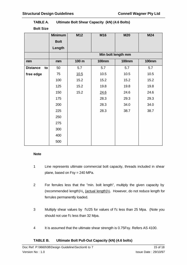
Structural Design Guidelines Connell Wagner Pty Ltd
Doc Ref: P:\9660\08\Design Guideline\Section6 to 7
Version No : 1.0 Issue Date : 29/10/97
15 of 18
TABLE A. Ultimate Bolt Shear Capacity (kN) (4.6 Bolts)
Bolt Size
Minimum
Bolt
Length
M12 M16 M20 M24
Min bolt length mm
mm mm 100 m 100mm 100mm 100mm
Distance to
free edge
50
75
100
125
150
175
200
225
250
275
300
400
500
5.7
10.5
15.2
15.2
15.2
5.7
10.5
15.2
19.8
24.6
28.3
28.3
28.3
5.7
10.5
15.2
19.8
24.6
29.3
34.0
38.7
5.7
10.5
15.2
19.8
24.6
29.3
34.0
38.7
Note
1 Line represents ultimate commercial bolt capacity, threads included in shear
plane, based on Fsy = 240 MPa.
2 For ferrules less that the "min. bolt length", multiply the given capacity by
(recommended length)½, (actual length)½. However, do not reduce length for
ferrules permanently loaded.
3 Multiply shear values by f'c/25 for values of f'c less than 25 Mpa. (Note you
should not use f'c less than 32 Mpa.
4 It is assumed that the ultimate shear strength is 0.75Fsy. Refers AS 4100.
TABLE B. Ultimate Bolt Pull-Out Capacity (kN) (4.6 bolts)

Structural Design Guidelines Connell Wagner Pty Ltd
Doc Ref: P:\9660\08\Design Guideline\Section6 to 7
Version No : 1.0 Issue Date : 29/10/97
16 of 18
Concrete capacity, full shear cone developed with bolt in direct tension using grade 4.6
bolts with the phi factor applied. For minimum depth of embedment the ultimate
capacity will be determined by the concrete but for reasonable embedment, the bolt
capacity will govern almost all the time. The table also assumes the ferrule is properly
anchored with an anchor bar or enlarged end into the concrete.
Bolt Size Max. Ultimate Bolt/Ferrule embedment length (mm)
Bolt Capacity 75 100 125 150 175 200 225
M12 12.1 39.4 67 103 146 197 256 322
M16 19.9 41.2 70 106 150 302 261 327
M20 35.3 43.0 72 109 154 206 265 333
M24 44.8 75 112 157 210 270 338
Note
1 Multiply table values by 0.85 for sand - lightweight concrete.
2 Multiply pull out capacity by f'c/32 for values of f'c less than 32 MPa.
3 Where the full concrete shear cone is not developed, e.g. close to the edge of
a concrete element, apply appropriate reduction factors.
4 Values shaded are given for use with the reduction factors, but the value used
should not in any case exceed the maximum ultimate bolt capacity.
6.5.8. Prototypes
Where there are many units of the one type, getting the first one correct with careful
inspection and proof of performance is important, e.g. lifting, handling, erection onto
fixings, etc., and careful study for cracks and if necessary, a testing programme.
Often prototypes are required to achieve the final finish for approval by the Architect or
where waterproofing, compaction or casting are of concern.
6.5.9. Notes to be Placed on the Precast Drawings
Refer to our standard notes for these.
Structural Design Guidelines Connell Wagner Pty Ltd
Doc Ref: P:\9660\08\Design Guideline\Section6 to 7
Version No : 1.0 Issue Date : 29/10/97
17 of 18
6.5.10.Typical Panel Connections
Refer to standard CAD details and past projects for these connections.
6.5.11.Load Bearing Precast
This type of construction is coming back into favour because of reduction of time on
the site and the fact the panel, the column etc. can often do two jobs - carry the
vertical load and provide a final finish or as formwork, etc. Tilt up is (usually) a form of
load bearing precast.
Members should be designed for lifting, minimum reinforcement. etc. and designed for
axial and lateral loads and frame moments to AS 3600.
Where member carry substantial axial load grouted dowels need to be used with fully
grouted end bearing to ensure full load transfer.
6.5.12.Tilt-up Construction
This form of construction is now very common, although it is not new. The tilt-up
panels originally were panels cast on the site and lifted into position, but often panels
can be made off site at a precast factory and delivered to the site.
Tilt up panels have a number of advantages. These include:
• Fast erections of walls, lift shafts, stair cases etc.
• Panels are usually load bearing.
• Variety of surface profiles and features available.
• Competitive with masonry.
• Suitable for sample type of panels.
It also has a number of disadvantages. These include:
• Space required on site for casting and cranage.
• Penetrations for services are difficult.
• Quality of panels cast on the site not as good as factory precast.

Structural Design Guidelines Connell Wagner Pty Ltd
Doc Ref: P:\9660\08\Design Guideline\Section6 to 7
Version No : 1.0 Issue Date : 29/10/97
18 of 18
• Complicated shapes are difficult to cast on the site.
• Generally butt joints can only be cast which can be difficult to waterproof.
• High quality off form or polished surfaces cannot be done. Often panels are
painted.
• Need for special fire rated ties to suit BCA Regulations.
For site cast panels grade 32 MPa should be used for panels lifted after 7 days and
grade 40 MPa for panels lifted after 3 days.
Design including cover etc. should be according to AS 3600.
The panel must be designed for:
• self weight
• lifting
• adhesion forces between the panel and the casting bed
• crane sling arrangement
• dynamic loading during lifting.
The "ARIES" computer program for panel design can be used.
Reinforcement should be according to the previous sections. A single layer of fabric
should ONLY be used in small panels of small thicknesses; eg 3m x 4m x 125 thick
or if thin panels are to be used with a single layer of fabric, then strong backs must be
used.
For larger panels; eg 6m x 3m x 150 thick, two layers of reinforcement can be used to
reduce cracking that may occur during lifting. If there is only one layer of
reinforcement then strong backs must be used for lifting.
Inserts for lifting must be properly anchored and the panels properly braced until
complete as part of the final structure.

Structural Design Guidelines Connell Wagner Pty Ltd
Doc Ref: P:\9660\08\Design Guideline\Section6 to 7
Version No : 1.0 Issue Date : 29/10/97
19 of 18
6.5.13.Floor Panels
There are a number of specialist precast floor panels available, including:
• Transfloor.
• Single and double tee units.
• Hollow core planks.
• Inverted U panels.
• Beam forms.
Refer to the manufacturer's information on standard design methods and details for
these elements. As floors act as diaphragms to transfer lateral loads to cores and
columns, it is essential these elements be properly tied together and to their
supporting structure so they can act as diaphragms.
6.5.14.Detailing
Designer should refer to previous major projects in their office and discuss typical
details with Senior Engineers and Drafters. Detailing is a very important part of the
design process and is often overlooked by designers. Buildability and ease of
construction are important matters. The following points should be noted:
• Drawings must realistically reflect all types of panels. Do not just draw a
typical panel. Draw all panels in sufficient detail to allow a shop drawing to be
prepared by others.
• Insist on the Architect fully detailing panels, dimensions and joints etc. Joints
are very important for water proofing and fire resistance. For high rise
buildings, use the open drained joint system, not butt joints if possible. Smoke
baffles may also be required. Discuss each joint with the architect so they are
aware of their responsibilities.
• Provide Y12 or Y16 trimmer bars around all edges including penetrations.
• Insist on the Architect detailing the fire proofing.

Structural Design Guidelines Connell Wagner Pty Ltd
Doc Ref: P:\9660\08\Design Guideline\Section6 to 7
Version No : 1.0 Issue Date : 29/10/97
20 of 18
• Reinforcement should be fabric of one sheet where possible.
• Provide reinforcement in both faces for panels greater than 150 thick.
• Do not skimp on fixings.
• Consider tolerances of the structure and expected movements both short term
and long term.
• Ensure sufficient panels and details are shown to allow the shop drawers to
detail panels fully.
• Check all rebates, drip grooves, joints etc. to ensure the reinforcement can be
fixed, including lifting hooks and ferrules.
6.5.15.Joints
Joints in precast can be a very important detail. Joints have a number of functions.
• Carry loads when load bearing
• Allow movement in non load-bearing panels
• Water proof precast
Often this area is ill-defined as it is part structural and part architectural and Architects
are often unaware of their responsibilities.
Once the structural requirements of the joint are determined, meet with the architect
and discuss each joint in detail, what is to be water proofed and how is it to be
achieved. Once a joint leaks it is very difficult to fix. Use stepped joints where
possible and appropriate flashings. A straight grouted joint has little resistance to
water. Wind can blow water upwards and through joints not properly sealed

Structural Design Guidelines Connell Wagner Pty Ltd
Doc Ref: P:\9660\08\Design Guideline\Section6 to 7
Version No : 1.0 Issue Date : 29/10/97
21 of 18
6.5.16.Standard Details
Connection must reflect the design requirements for the building as a whole; ie axial
shortening, sway.
The designer should also refer to previous projects with major precast and standard
details developed on CAD.
6.5.17.Shop Drawings
Refer to the Section in this Manual on shop drawings for specific comments.
Shop drawings are important documents that should be treated with respect and care.
Generally, the standard of the larger Subcontractors shop drawing is high. Checking
must ensure the full requirements of our design are shown on the shop drawings.
We do not normally check dimensions unless Prime Consultants have dimensioned
the panels on the drawings.

Structural Design Guidelines Connell Wagner Pty Ltd
Doc Ref: P:\9660\08\Design Guideline\Section6 to 7
Version No : 1.0 Issue Date : 29/10/97
1 of 29
7. STRUCTURAL STEELWORK
7.1. Introduction
The design of structural steelwork in building structures should be in accordance with
the limit state requirements of AS 4100 and AS 4600. The design is carried using
design actions based on the loading codes. Unless specifically requested, use only
steel sections manufactured by BHP.
7.2. Codes
AS 3990 Mechanical Equipment - Steelwork (old AS 1250)
AS 4100 Steel Structures
AS 4600 Cold-Formed Steel Structures
7.3. References
1. “Steel Designers Handbook” - Gorenc, Tinyou, Syam 6th Ed.
2. “Introductory Structural Design” - Structural Steel Design AS 4100" - R.D.
Nielsson (University of Queensland)
3. “Design Capacity Tables for Structural Steel - Vols. 1 and 2" AISC AS 4100
“Steel Structures” Code
4. “Limit State Design of Portal Frame Buildings” - Woolcock, Kitipornchai,
Bradford
5. “Fastener Handbook” - Ajax Fasteners
6. “Steel Structures Design Handbook” - Standards Australia SAA HB48-1993
7. “Design of Structural Connections” Hogan and Thomas (AISC)
8. Code of Practice for Safe Erection of Building Steelwork, Parts 1 & 2
“Design Guide - CHS Joints”, Packer Kurobane, et. al; CIDET
“Design Guide - RSH Joints”, Packer Kurobane, et. Al; CIDET
9. Design capacity tables for Duragal Steel Hallow Sections.
10. Duragal Design Capacity Tables for Structural Steel angles, channels and flats
11. BS8100 Part 1, 1986, Lattice Towers and Masts
12. “Wind Forces on Tubular Structures - Design Manual”, Tubemakers of Australia,
August 1987

Structural Design Guidelines Connell Wagner Pty Ltd
Doc Ref: P:\9660\08\Design Guideline\Section6 to 7
Version No : 1.0 Issue Date : 29/10/97
2 of 29
7.4. Technical Notes
There are numerous Connell Wagner Technical Notes available - refer to library list.
7.5. Purlins and girts
7.5.1. Design
Note: Manufacturers load capacity tables are based on peak moments usually in the
end spans. Significant savings can be made in the purlin selections by using methods
(a) or (c).
(a) In accordance with AS 4600 ‘AS Cold Formed Steel Structures’ which has
specific sections governing purlin design.
(b) Comprehensive design tables by the major suppliers based on load tests and
calculations. The loads are calculated using permissible stress combinations
New . Check manufacturers data as future capacity tables may be in limit
state format. Note: the use of these tables is conservative for large multi span
or varying span buildings.
(c) i) Analyse design loads to obtain Reactions and Bending Moments for an
assumed spacing.
ii) Using the manufacturer’s tables for similar spans, effective lengths etc
ascertain midspan capacity and lapped moment capacity for various
purlins sizes, and bridging configurations.
iii) Select appropriate purlins.
iv) Iterate or modify for different spacings.
The permissible stress format design loading combinations are:
a) DL + LL or
b) 0.75 (DL + LL + WL in direction of DL and LL) or
c) Minimum possible DL - WL in direction opposite to DL
d) Max DL ± WL
Note: Allow for local wind pressure effects.

Structural Design Guidelines Connell Wagner Pty Ltd
Doc Ref: P:\9660\08\Design Guideline\Section6 to 7
Version No : 1.0 Issue Date : 29/10/97
3 of 29
7.5.2. Use of Purlins and Girts
Purlins and girts are major cost item, particularly in industrial buildings. The selection
of purlins and girts should not be underestimated.
a) Tolerances and Out of Straightness
Lysaght/BHP have a tolerance of span/500 for purlins and girts. A
specification of span/600 with a maximum of 20mm is preferred. This means
a 10m purlin can have up to 20mm out of straightness in either direction.
b) Bridging for Roofs
Bridging is necessary to provide both stability during erection of sheeting and
as a restraint to the compression flange for the design case of outward wind
load. Refer manufacturer’s details for bridging systems.
Where the roof is not symmetrical (e.g. skillion roof) and bridging is required,
it is necessary to provide flat strap bracing, rod bracing, or light angle bracing
to prevent the purlins from deflecting down the slope.
Bridging is required during erection to resist the tendency for the purlins to roll
over before the sheeting screws are installed. This situation is not adequately
allowed for in manufacturer’s design tables. It is a good policy to use one
central row of bridging even though this may not be required by design tables.
Bridging on curved roofs needs special care and thought. Standard bridging
systems do not cover this situation.
c) Bridging for Wall Girts
Struts or hangers are required to prevent the girts sagging between columns
during fixing of the wall cladding. Use struts except where cladding is fixed
prior to casting of the concrete floor, or where there are obstructions such as
off-set brick walls or openings. Alternatively hang the bridging from a
structural eaves member, or to using a light truss incorporating girt chords
and flat diagonal bracing or diagonal sag rods.

Structural Design Guidelines Connell Wagner Pty Ltd
Doc Ref: P:\9660\08\Design Guideline\Section6 to 7
Version No : 1.0 Issue Date : 29/10/97
4 of 29
d) Shallow Roofs and Deflections
Differential deflection of adjacent purlins can flatten a 1.5° to 2° roof pitch
causing water ponding and leakage through the side laps of the sheeting.
Also, if the roof is visible, it may be aesthetically unacceptable.
Roof pitches 3° to 7° are susceptible to water ingress at joints and will need
to be in one continuous sheet or comprise specifically detailed parts/laps.
Where possible, use a minimum 5° pitch. Never use less than the minimum
pitch recommended by the sheeting manufacturer.
e) Curving of Purlins and Girts
Cold formed purlins and girts cannot be curved.
f) Curved, Feature, Complicated and Bull-Nosed Roofs
Where specific architectural features such as bull-nosed sheeting or special
cladding details are required, it is important that tolerances are taken into
account. A secondary framing system with adjustable light gauge angles
fixed to the purlins or girts will often be required.
Bull-nosed sheeting is difficult to fix and has rolling tolerances from sheet to
sheet. It is preferable that the bull-nose sheeting has a bull-nose together
with a minimum straight length of sheeting over two purlins. This allows the
roofer to fix the sheeting and overcome any out of tolerance between
individual sheets by springing the sheet.
g) Hole Tolerance
Holes punched in purlins are generally 18 x 22 long slots to take M12 bolts.
(22mm holes and M16 bolts in Big Zeds). This can cause a number of
problems in connection with bracing and alignment.
With such large tolerances, the use of purlins as bracing and for the
transmission of forces needs to be considered carefully. Designers must be
aware of and detail for a slip of 5 to 10mm longitudinally in a purlin system.
h) Hips, Valleys and Sides

Structural Design Guidelines Connell Wagner Pty Ltd
Doc Ref: P:\9660\08\Design Guideline\Section6 to 7
Version No : 1.0 Issue Date : 29/10/97
5 of 29
Ends of sheets at hips and valleys and sides of sheets at walls, etc. must be
continuously supported. A 50 x 50 x 1.2 cold formed angle is often sufficient.
Be aware of possible need for valley gutters and the extended cleats required
for them. Forgetting these trimming angles is embarrassing and costly.
i) Purlin Cleats
Purlin cleats are subjected to axial loads and bending moments. The bending
moments result from the component of the weight of the roof sheeting in its
own plane, from the restraint provided by the sheeting to prevent lateral
buckling, and in the case of Z profiles, from lateral forces due to the inclination
of the principal axes to the plane of the roof.
Be aware that the size of these cleats is dependent on both the height and
the roof slope. Always check any “standard cleat” detail. Top flanges of
beams may require additional detail to maintain support for lateral torsional
buckling.
7.6. Beams
7.6.1. General
Design information for flexural members such as beams is comprehensively set out in
various well known references e.g. [1].
7.6.2. Connections
Refer to Section 9 of AS4100 for minimum design loads for connections. Connection
designs as set out in reference [7] are recommended for use. The tabling of
connection design loads on drawings to allow fabricators to prepare their own
connections is to be avoided. Limit state connection capacity tables are contained in a
Connell Wagner Design Aid. Do not skimp on connections. They are important
elements. Failure of these can be catostraphic.
7.6.3. Effective Lengths, Moment Gradient
Information on effective lengths is available in the Steel Code.

Structural Design Guidelines Connell Wagner Pty Ltd
Doc Ref: P:\9660\08\Design Guideline\Section6 to 7
Version No : 1.0 Issue Date : 29/10/97
6 of 29
7.6.4. Members Subject to Bending
Checking of members subject to bending:
(i) Determine the bending moment diagram, the type of supports and lateral
restraints.
(ii) For long span beams (> 25 times beam depth), first check the serviceability
limit of deflection, it will often be the control for long span beams.
(iii) For other beams, check the strength limit states:
a. Member Bending Capacity
• calculate the section capacity to provide a basic load capacity
irrespective of length
• calculate the member capacity which allows for member length
• check the adequacy of the restraining elements
b. Shear Capacity
c. Check the bearing condition at the support and if necessary provide
load bearing stiffeners.
Note: If a section is compact the effective section properties are the same as
the gross section properties. If the section is non-compact or slender, the
effective section properties are less than the gross section properties. Note
that the minimum radius of gyration ry is based on GROSS section geometry.
7.6.5. Angles as Beams - Extract from Reference (6)
For angles which are torsionally restrained at supports with the load applied at:
(i) the shear centre for angles with lateral restraints, or
(ii) the middle of the leg for angles without lateral restraints
The following approximation is applicable:

Structural Design Guidelines Connell Wagner Pty Ltd
Doc Ref: P:\9660\08\Design Guideline\Section6 to 7
Version No : 1.0 Issue Date : 29/10/97
7 of 29
(a) For an angle under continuous lateral restraint (see Figure 5.4a) subject to a
design moment M* about an axis n-n normal to the leg, it is recommended that
M* ≤ 0.9 fy Ze with Ze = 1.25 Z min
where Zmin is the minimum elastic section modulus about the relevant axis
normal to the leg.
(b) For an angle without lateral restraint (see Fig.5.4b) subject to the design
moment M* about an axis n-n normal to the leg, it is recommended that
M* ≤ 0.9 a fy Ze
where a is a reduction factor to be determined as follows:
• for equal angles a = 0.7
• for unequal angles with loading
parallel to short leg a = 0.8
parallel to long leg
- with leg up a = 0.6
- with leg down a = 0.5
Shear capacity may control the design of angles as beams for the following
situations:
(i) Equal angles of 150mm and 200mm legs with spans less than 4m
(ii) All other angles with spans less than 2m
7.6.6. Members Subject to Axial Compression
The procedure for checking a member subject to compression is as follows:
(i) Estimate the kf value for the section using the BHP Handbook or similar; for
fabricated sections use Section 6.2 of AS 4100.
(ii) Estimate the design section capacity i.e. the short column capacity Ns = 0.9 kf
Anfy.

Structural Design Guidelines Connell Wagner Pty Ltd
Doc Ref: P:\9660\08\Design Guideline\Section6 to 7
Version No : 1.0 Issue Date : 29/10/97
8 of 29
(iii) Select the member section constant ab, to allow for residual stresses and
section type.
(iv) Estimate the member effective length factor ke.
(v) Estimate the slenderness ratio (keL / r) for the relevant buckling axis.
(vi) Obtain the member slenderness reduction factor ac.
(vi) The axial load nominal design capacity is acNs.
Note that all columns in simple construction should be designed for a nominal load
eccentricity as per AS 4100 and therefore must be checked for combined axial
compression and bending.
7.6.7. Members Subject to Combined Action
The interaction equation for a section subject to an axial load, N*, a major axis bending
moment, M* x, and a minor axis moment M* y:
N* + M*x + M*y
___ ___ ____ <1.0
0.9N 0.9Mbx 0.9Mby
where
N = Nt or Nc = the nominal axial tension or compression capacity, respectively, of the
member (for a compression member it is the lesser of the capacities for either
principal axis).
Mbx = nominal capacity of the member in bending about the x-axis.
Mby = nominal capacity of the member in bending about the y-axis
Note: This is a simplified procedure which avoids the need for checking section and
member capacity separately. Considerably less conservative results can be obtained
by using the more complex checking procedure of AS4100.
Refer to Appendix B of [6] and [1] for more detail.

Structural Design Guidelines Connell Wagner Pty Ltd
Doc Ref: P:\9660\08\Design Guideline\Section6 to 7
Version No : 1.0 Issue Date : 29/10/97
9 of 29
7.6.8. Penetrations
(a) Recommended dapped end and penetration details are shown in figures 7.1
and 7.2 These are mostly applicable to composite floor construction, where
the reticulation of underfloor services, especially airconditioning ductwork, is a
prime consideration.
Figure 7.1 Penetration Details
Figure 7.2 Reduced Depth At Beam End
Alternatively, plateflange welded toweb

Structural Design Guidelines Connell Wagner Pty Ltd
Doc Ref: P:\9660\08\Design Guideline\Section6 to 7
Version No : 1.0 Issue Date : 29/10/97
10 of 29
7.6.9. Allowable Deflections The allowable deflections are to be approximately as shown in the table below.
Deflection Limits Purlins And Girts All Rafters Mullions Supporting Brittle Finish Walls Supporting Other Walls Eaves Deflection (Horizontal) Multi-Storey Building Industrial Building With Crane - requires careful specs. Refer reference1 “Crane Runway Girders" Industrial Building Floor Beams Supporting Brittle Walls No Provision For Movement Supporting Brittle Walls/Ceilings Some Provision For Movement Not Supporting Walls/Ceilings That Could Be Damaged By Movement Fascias Glazing Heads
Span Multiplier 1/300 1/150 1/150 But Max. 30mm 1/300 But Max. 50mm 1/150 1/150 But Max. 30mm 1/500 1/200 Knee Height Multiplier 1/500 1/300 1/150 1/300 1/100 Span Multiplier 1/1000 1/500 But Max. 20mm 1/300 But Max. 30mm 1/500 But Max. 20mm 1/500 But Max. 10mm
Load Type DL WI Wl DL WL WL WL WL WL LL WL WL WL Dl+LL Dl+LL LL DL DL
Remarks No Ceilings With Ceilings No Ceilings With Ceilings Metal Cladding Masonry Cladding Farm Building Deflection Due To WL As For Millions
Structural Design Guidelines Connell Wagner Pty Ltd
Doc Ref: P:\9660\08\Design Guideline\Section6 to 7
Version No : 1.0 Issue Date : 29/10/97
11 of 29
7.7. Trusses
7.7.1. General
Trusses have been used in Australia to efficiently span distances up to 120m.
Trusses are usually of the Warren, Pratt or Fink types. Trusses should be configured
such that panel points are evenly spaced, the top chord has adequate slope for roof
drainage and the diagonals meet the chord members between 35° and 55° to avoid
awkward connections. Large span trusses warrant the use of as large a purlin as
possible to achieve the maximum possible spacing (10 - 12m). Long lengths of
roofing material are not readily available, and overlapping may require special purlin
details.
7.7.2. Analysis
Bending moments in the truss members may arise from:
a) Frame moments
b) Joint eccentricities
c) Lateral loads between nodes
It is acceptable to ignore moments resulting from frame action, assume all members
are pin-jointed. However, moments due to joint eccentricities and applied loads
between nodes must be considered.
7.7.3. Member Sizing
Members must be sized to resist axial load and bending moments. Effective lengths
of members are dealt with in [1]. Out of plane (horizonal) buckling capacity of the
compression chord is improved by using a UB with web horizontal.
7.7.4. Connections
The detailing of connections has a significant effect upon the economics of trusses.
Smaller trusses may utilise gussetless connectors. Refer to Figures 7.3 and 7.6.
Heavier trusses require gussets to distribute web member loadings into the chords.
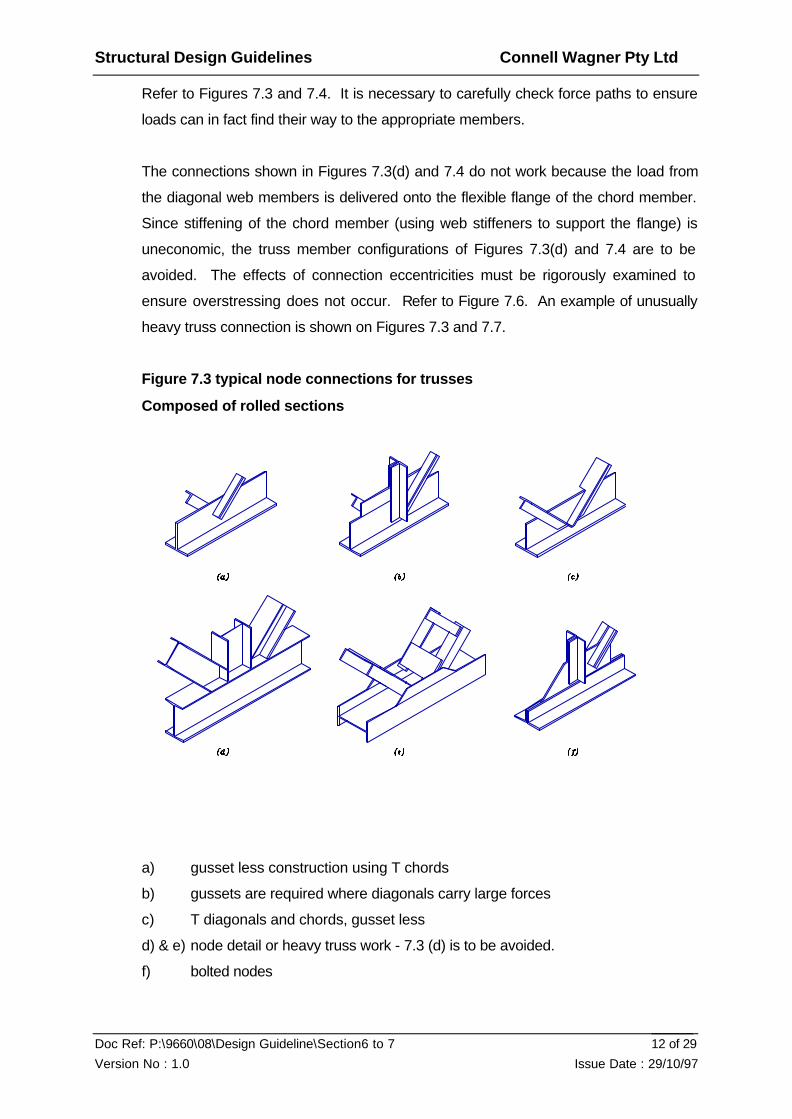
Structural Design Guidelines Connell Wagner Pty Ltd
Doc Ref: P:\9660\08\Design Guideline\Section6 to 7
Version No : 1.0 Issue Date : 29/10/97
12 of 29
Refer to Figures 7.3 and 7.4. It is necessary to carefully check force paths to ensure
loads can in fact find their way to the appropriate members.
The connections shown in Figures 7.3(d) and 7.4 do not work because the load from
the diagonal web members is delivered onto the flexible flange of the chord member.
Since stiffening of the chord member (using web stiffeners to support the flange) is
uneconomic, the truss member configurations of Figures 7.3(d) and 7.4 are to be
avoided. The effects of connection eccentricities must be rigorously examined to
ensure overstressing does not occur. Refer to Figure 7.6. An example of unusually
heavy truss connection is shown on Figures 7.3 and 7.7.
Figure 7.3 typical node connections for trusses
Composed of rolled sections
a) gusset less construction using T chords
b) gussets are required where diagonals carry large forces
c) T diagonals and chords, gusset less
d) & e) node detail or heavy truss work - 7.3 (d) is to be avoided.
f) bolted nodes

Structural Design Guidelines Connell Wagner Pty Ltd
Doc Ref: P:\9660\08\Design Guideline\Section6 to 7
Version No : 1.0 Issue Date : 29/10/97
13 of 29
Figure 7.4 UB And RHS Truss
Figure 7.5 Truss Connections With Tubular Sections

Structural Design Guidelines Connell Wagner Pty Ltd
Doc Ref: P:\9660\08\Design Guideline\Section6 to 7
Version No : 1.0 Issue Date : 29/10/97
14 of 29
Typical connections for roof trusses composed of tubular sections:
(a) connections using contoured tube ends
(b) & (d) reinforcing plate bent to tube curvature is often required at node
connections
(c) when negative eccentricity is used no reinforcing plate is required
(f) concentric reducer can be used where tubes are stepped down
(g) slotted-gusset connections are popular with fabricators who have no facilities
for contour cutting
(h) flattened end connections also avoid contour cutting
(i) slit tube connections
Figure 7.6 Gusset-Free Connections For Trusses
(a) centre of gravity lines intersect at the node
(b) eccentric connection can be a practical way of detailing but additional bending
stresses are induced as indicated in (c).
(c)

Structural Design Guidelines Connell Wagner Pty Ltd
Doc Ref: P:\9660\08\Design Guideline\Section6 to 7
Version No : 1.0 Issue Date : 29/10/97
15 of 29
Figure 7.7 Heavy Truss Connections
7.7.5. Fabrication, Transport and Erection
Large trusses may have to be fabricated in pieces to allow transport to site and field
splicing. Transportation limitations differ from state to state and should be checked
locally. Field splicing is usually by bolting but may, for very large trusses, be by
welding.
7.7.6. Weld Testing
For major jobs, a specialist welding inspector should be employed by the client or the
Company. It is necessary to specify the extent of non-destructive (and destructive)
testing in some detail (e.g. 100% of 50% of the welds etc.) and to show clearly on the
drawings which welds are to be tested. Non-destructive testing is usually the
ultrasonic method. Contractual arrangements as to who pays for testing vary but
should be clearly stated.
7.8. Portal Frames
7.8.1. General
Use frame programs for the design bending moments. Do not use coefficient as it is
inefficient. It is recommended that each loading for internal pressure, external
pressure etc. be analysed and combined with appropriate factors. This makes it
easier to reanalyse various conditions and makes checking simpler.

Structural Design Guidelines Connell Wagner Pty Ltd
Doc Ref: P:\9660\08\Design Guideline\Section6 to 7
Version No : 1.0 Issue Date : 29/10/97
16 of 29
The first trial run through the program must utilise assumed section sizes and these
should be refined for the final run, although the bending moment pattern is often not
highly sensitive to moderate variations in section size. Haunches should be input as a
number of short prismatic members ( 3 is usually adequate) of differing section
properties to model the haunch reasonably accurately, since bending moments vary
quickly in these areas. Fixed base portals should be avoided (refer to the section on
footings). However, depending on the footing type and base plate detail, a “partial-
fixity” may be generated at a base under serviceability loads.
7.8.2. Rafters
Rafter size is normally determined by bending moments, but occasionally by
deflections. The use of knee haunches means that the apex bending moment
governs the rafter size. Account should be taken of the beneficial effect of bending
moment shape factor (µm) which is automatically calculated in Limsteel. Refer 2.5.4.
Note that deletion of fly braces, by assuming the tension (top) flange provides bracing,
needs to be justified by rigorous analysis.
7.8.3. Beam Columns
Axial loads in columns are usually low except:
• where the column receives loads from a crane;
• where the column forms part of a wall bracing panel.
Specific guidance about effective lengths for columns supporting crane loads is
contained in [4]. Column bases, even where pinned bases are assumed for analysis
purposes, provide sufficient torsional restraint to have a significant effect upon
effective length of columns. Flybracing to columns is often overlooked, (especially
where the knee moment is the governing moment), and is often necessary. Crane
support beams, where they are supported off brackets on the columns provide
torsional restraint to the column if they are positively restrained against longitudinal
movement.
Structural Design Guidelines Connell Wagner Pty Ltd
Doc Ref: P:\9660\08\Design Guideline\Section6 to 7
Version No : 1.0 Issue Date : 29/10/97
17 of 29
Note that column moments usually decrease from a maximum at the top (use the
moment at the underside of the haunch) to zero at the bottom (pin base) and may
even reverse on the way down if lateral wind loads are acting. This has a significant
effect on the lateral torsional buckling capacity. Major and minor axis axial buckling
must also be considered since either can govern in combination with lateral torsional
buckling.
7.8.4. Columns
Central columns may be considered to be “sidesway prevented”.
Be aware of minimum design eccentricities and moments created by beam
connection details required under AS 4100.
7.8.5. End Wall Mullions
Two cases can occur:
• Future expansion is envisaged. All frames, including the end ones, are the
same moment resisting portals. End wall mullions are connected to the rafters
with vertically slotted holes of the appropriate length. No uplifts occur on the
columns which can be supported on slab thickenings.
• Future expansion is not envisaged. The end frame is a braced column/rafter
system. The end wall mullions receive uplift. This system may be no cheaper
than the case above. The end wall may be masonry, concrete or sheeted.
Check relative lateral deflections of portals and end frame, particularly if the end frame
is braced. Braced end frames with roof bracing back to the first portal will attract 1.5 -
2.0 times the “design” load which must be recognised in the design of the end wall
bracing.
7.8.6. Flybraces
Flybraces can take a variety of forms. Double angle, single angle and double strap
types have been used. The single angle type is normally the most economic. 38 x 38
x 3 L bracing is the smallest that should be used to accommodate a 12mm bolt. The

Structural Design Guidelines Connell Wagner Pty Ltd
Doc Ref: P:\9660\08\Design Guideline\Section6 to 7
Version No : 1.0 Issue Date : 29/10/97
18 of 29
lower purlin lap bolt hole can be used to connect the flybracing. Check the purlin for
this force in conjunction with its full design load to create worst scenario.
For beams and columns bigger than 410 UB provide a fly brace at the following
locations:
(a) Knee of portal frame.
(b) Ridge of portal frame.
(c) At regular intervals along the member to satisfy the assumed effective length.
7.8.7. Connections
(a) General
Opinion varies amongst designers and fabricators as to which knee joint detail
is the most economical in conjunction with the rafter splices. Where possible
confer with the known fabricator to determine the cheapest details.
Use Connell Wagner standard details in the absence of a known fabricator.
Connections should be designed, wherever possible, using AISC Standardised
Connections and Connell Wagner design aide. The terminology used in this
publication should always be used.
AISC standardised connections have been developed for the total industry
including designers, shop detailers and fabricators. Engineering design
drawings need only convey the essential strength characteristic of the
connections, e.g. size of component parts, number of bolts, etc. Bolts,
centres, coping sizes, etc. need not be shown, although of course, they must
be taken into account in the design.
Connections are critical components in the overall strength of structural
steelwork so a conservative approach is recommended. Full strength butt
welds are very expensive and their use should be minimised. Adopt partial
penetration butt welds instead wherever possible.
(b) Notes on Connections

Structural Design Guidelines Connell Wagner Pty Ltd
Doc Ref: P:\9660\08\Design Guideline\Section6 to 7
Version No : 1.0 Issue Date : 29/10/97
19 of 29
1. Wherever possible, use simple repetitive connections.
2. Dimension of all plants, bolts and spacings. Do not leave it to the shop
drawer to guess what you intended.
3. Web side plate connections are the simplest, allow easy erection for
small sections and provide a small length tolerance. If the supporting
member is not free to rotate (e.g. restrained by an adjacent beam on the
opposite side of the web) fixity moments develop which can overstress
the components.
4. Angle cleat connections are simple, provide some rotational freedom (i.e.
component parts are not overstressed by fixity moments), and can be
used each side of the same web. They are recommended for beam to
beam connections for heavy sections.
5. Angle seat and shear plate connections give excellent length tolerance
and are easy to erect. Top restraining cleats should be detailed to permit
end rotation of the supported beam. They are recommended for beam to
column connection for heavy sections.
6. Flexible end plate connections cannot be used on both sides of the same
web. Beams cannot be independently erected.
7. Flexible end plate connections cannot be used on both ends of the same
beam when the supporting members cannot be spread during erection.
This is the normal situation.
8. Flexible end plate connections do not provide any length tolerance.
Consideration should be given to the use of shim plates.
9. Flexible end plate connections provide some rotational freedom and give
good torsional restraint to the supporting member.

Structural Design Guidelines Connell Wagner Pty Ltd
Doc Ref: P:\9660\08\Design Guideline\Section6 to 7
Version No : 1.0 Issue Date : 29/10/97
20 of 29
10. Steelwork to insitu concrete connections requires large erection
tolerances.
Generally, use cast-in weld plates with suitable shear connections (flash
butt welded studs or reinforcement bar) and site welded shear plate or
angle cleat connections. Ensure that the connection provides end
rotational freedom. Always specify the erection tolerances and non-
destructive testing for site welds.
(c) Bolted Joints
1. Design on the basis of threads included in the shear plane.
Standard bolt is to be M20 - 8.8 N/S. The "N" signifies threads in the shear
plane.
2. Standard pitch 70mm
Standard edge distance 35mm
3. Commercial and high strength bolts used for structural work are available
in sizes M12, M16, M20, M24, M30 and M36. (M12 may not be available in
grade 8.8).
M12 - normally used for purlins and girts
M16 - minor steelwork, lightly loaded
M20, M24 - general structural connections, holding down bolts
M30, M36 - holding down bolts
4. Usage
• Use 8.8/TF bolts, only where a non-slip condition is required, e.g. a
cantilever moment connection or portal rafter connection using bolted
flange plates. TF bolts over M24 are very difficult if not impossible to
tensions.

Structural Design Guidelines Connell Wagner Pty Ltd
Doc Ref: P:\9660\08\Design Guideline\Section6 to 7
Version No : 1.0 Issue Date : 29/10/97
21 of 29
• Avoid the use of tensioned and untensioned high strength bolts, e.g.
8.8/S and 8.8/TF on the same project because it is hard to clearly
determine on site which bolts are to be tensioned and which bolts are
not to be tensioned.
• Pay careful attention to specification items regarding the non-painting
of plate interfaces with 8.8/TF bolts. (Note: inorganic zinc silicate
paint over a class 2½ preparation is acceptable on faying surfaces).
• 8.8/TF bolts are recommended to be used with Coronet load indicator
washers with no specified clearances. Normally, 0.40mm is used on
site, but lesser clearances may be required in particular locations, i.e.
when exposed to weather or moisture.
• Specify all bolts to be coated with some protection. Coating systems
available are galvanised, zinc plated, cadmium plated, chromium
plated and head/tin plated. The Ajax fasteners handbook provides
further guidance.
(d) Column Bases
Design
Refer to [4].
Design portal frame column bases usually as pin ended.
If lateral deflections are a problem provide fixity to the column base.
Compare deflections for pinned and fully fixed base and decide what
degree of fixity will be used for serviceability case only.
Design the footings for the selected column base moment and vertical and
horizontal reactions. Be aware that a small footing rotation may totally
relieve the portal base moment.
Structural Design Guidelines Connell Wagner Pty Ltd
Doc Ref: P:\9660\08\Design Guideline\Section6 to 7
Version No : 1.0 Issue Date : 29/10/97
22 of 29
Fixed column bases should not be considered where the foundation
bearing capacity is less than 400 kPa, as the footing must be prevented
from rotating and releasing the column moment. Be aware that soil creep
can occur, even in stiff clay.
Base Plates
Use a minimum thickness of 16mm for portal frames. For small columns
door frames and the like. 1.0 mm plates may suffice.
Bolt edge distance (minimum) is to be 1.6 x bolt diameter.
Base plate widths are to match standard plate widths where possible.
Holding Down Bolts
Use a minimum of 4 bolts for columns in portal frames or larger structures
so that they can free stand during erection. Use adjusting nut and washer
under the plate in certain circumstances. Allow adequate clearance under
the base plate for nut adjustment e.g. 50mm.
Design bolts for combined shear plus axial tension. Do not consider bolt
in bending.
For particularly large shear forces a shear key may be required.
(e) Welding
Welding is widely used in portal frame fabrication, and may be classified into
the categories of general purpose welding (GP) (not highly stressed) and
special or structural purpose welding (SP). SP welds require testing (usually
non-destructive) in accordance with the welding code. SP welds are normally
used and designers should ensure that appropriate notes are incorporated on
drawings and specifications.

Structural Design Guidelines Connell Wagner Pty Ltd
Doc Ref: P:\9660\08\Design Guideline\Section6 to 7
Version No : 1.0 Issue Date : 29/10/97
23 of 29
The welding code requires that the exact extent of non-destructive testing
(usually ultrasonic for fillet welds) be specified (e.g. 50% of length of 100% of
the welds, 100% of length of 50% of the welds etc.). This information must be
shown on the drawings. A specialist welding inspector should be employed by
the Company for major works.
It is highly recommended that all designers attend “handyman” welding
courses. This is the only effective way of gaining a real perspective on the
limitations and difficulties inherent in welding.
(f) Weld Testing
Welding shall comply with AS 1554.1, AS 1554.2 or AS 1554.5 as appropriate,
in accordance with AS 4100, clause 9.7.
Whilst methods of testing of welds are covered in AS 1554, the extent of
testing is left to the discretion of the engineer.
The weld category and type and extent of testing must be shown on the
drawings (AS 1554.1, Clauses 3.1.3, 7.4.1). Testing is dependent on the
category of weld required (GP or SP).
For guidance on the extent of testing required, refer to the following code
provisions:
AS 1554.1 - Clause 1.6 Weld Categories
- Section 6 Quality of Welds
- Section 7 Inspection
Appendix A Selection of Weld Category
Appendix F Suggested Extent of Non-Destruction Examination
AS 4100 - Clause 11.1.5 Designation of Weld Category (For Fatigue)
- Clause 13.8.2 (c) Requirement for Seismic Zone 1

Structural Design Guidelines Connell Wagner Pty Ltd
Doc Ref: P:\9660\08\Design Guideline\Section6 to 7
Version No : 1.0 Issue Date : 29/10/97
24 of 29
It is recommended that for major structural projects, the provision of AS 4100,
Clause 13.8.2 (c) is adhered to, irrespective of the Seismic Zone applicable.
All principle site welds should be non-destructively examined.
All butt welds must be tested.
Testing should be carried out by an independent approved NATA testing
authority. We are not welding experts and most experienced engineers would
not know a satisfactory weld by visual inspection.
If weld testing is required, it should be discussed (before tender) with the
testing authority to obtain their comments on the extent of testing, type of weld
testing, weldability of details, etc. This must then be specified with technical
details and the cost of testing allowed for, either as a PC sum or a cost to be
borne by the Contractor and/or steel fabricator.
The weld testing specification should include actual joint samples which should
be prepared and tested before fabrication commences. The welding inspector
should also visit the fabrication shop and inspect all welding on a regular basis
as part of their testing procedures.
7.8.8. Bracing
Frames are normally braced against longitudinal racking by roof and wall bracing. If
reinforced masonry or precast concrete (often tilt-up) walls are used, the portal frames
may be tied to these for longitudinal stability. Light wall bracing is still needed for
stability during erection and will usually be sized by the fabricator/erector. Extra loads
on the columns in the braced bay, and its supported footings, are induced by wall
bracing. Footing sizes normally increase in the braced bay. Column sizes should be
checked as extra column flybracing may be required.
Rods can be difficult to erect and require adjustment. Sag should be prevented by
hook bolts attached to purlins.
Use equal angles (or CHS for larger spans and forces).

Structural Design Guidelines Connell Wagner Pty Ltd
Doc Ref: P:\9660\08\Design Guideline\Section6 to 7
Version No : 1.0 Issue Date : 29/10/97
25 of 29
Design angles to buckle about X-X axis not V-V.
The effect of self weight moment on axial capacity is significant. Refer [4].
Check effect of sag on axial capacity if sag is greater than length divided by 200.
Connect as per Connell Wagner standard detail.
7.8.9. Roof Bracing
Roof bracing may be cross bracing (diagonal members usually rods or angles
designed for tension only), or a trussed system (diagonal members, usually tubes, to
take compression/tension). Except for small structures where purlins may provide
this strut action, provide property designed struts. Refer to Section 6.5.2 (g).
Bracing of internal bays requires running struts in the roof to the end walls unless the
purlins can take the axial load. (As a general rule, end bays should be braced to
facilitate erection). In portal systems this can provide problems of differential lateral
drift due to the end bays high stiffness.
Rod cross bracing should be avoided in all but small buildings since the preload to
minimise sag is impossible to monitor and can overstress the compression struts.
The bracing plane should be carefully chosen to avoid conflicts between the bracing
and purlins, flybracing etc. Mid-height of rafters is common.
Use purlins as struts in other bays to carry load into braced bay. Check the purlin
capacity for combined axial and bending loads if purlins are to carry end wall forces.
End wall rafters will distribute concentrated mullion load into 2 or 3 purlins by
transverse bending if required.
Use compression (not cross) bracing configuration as this may be the most cost
efficient in materials and ease of erection.
Eccentricity exists between the top of end wall columns and the level of the roof
bracing. If the eccentricity and/or loads are large, thought needs to be given at the

Structural Design Guidelines Connell Wagner Pty Ltd
Doc Ref: P:\9660\08\Design Guideline\Section6 to 7
Version No : 1.0 Issue Date : 29/10/97
26 of 29
early design stages to how the load gets from the column connection to the roof
bracing. Roof bracing cleats are often large since this connection needs to
accommodate small eccentricities of the centre lines of the bracing numbers.
Connections which rely on web shear and bending to transfer bracing loads will not
work for significant loads. Particular care is required to transfer roof bracing loads into
the wall bracing without relying on web bending in the frame rafters. Economic end
connections for tubes are based on research carried out by Kitipornchai [4].
(Note that stressed skin bracing design is still not widely used and is not acceptable to
many local authorities and is difficult and expensive to detail. Normal roof sheeting
practice is not stressed skin bracing).
7.8.10.Wall Bracing
The connection of wall bracing to the web of the column using a vertical cleat plate will
usually overstress the column web in bending unless it is encased in concrete.
Alternately at the base, the bracing cleat can be welded to the baseplate and the
column web. The baseplate will prevent the column web bending.
Masonry/Concrete Walls
Reinforced concrete blockwork is often used to form the walls and may obviate the
need for wall bracing. Concrete walls will usually be precast, and may be either
factory precast or site tilt-up. Masonry walls parallel to portal frames attract
significantly higher lateral forces due to the relatively large stiffness. Take care with
connection details. These walls will usually require lateral restraint at the top from a
wind beam (channel or I beam with web horizontal). The walls must be positively fixed
to the wind beams, preferably with expanding anchors, to provide restraint to the walls,
and also to provide longitudinal restraint to the building.
Be aware that chemical anchors will fail in a fire situation. Ensure that there is
adequate connectivity to guarantee stability in a fire - refer to Precast Concrete section
- refer Building Code of Australia for requirements.
Expansion Joints

Structural Design Guidelines Connell Wagner Pty Ltd
Doc Ref: P:\9660\08\Design Guideline\Section6 to 7
Version No : 1.0 Issue Date : 29/10/97
27 of 29
Generally for “shed” type buildings consider use of an expansion joint if the building
length exceeds 100m.
For other types of building consider the effect of thermal movements on attached
architectural or rigid elements.
7.8.11.Temperature Range
When calculating thermal movements in purlins use:-
a) No insulation - temperature range 50°C.
b) insulated - seek advice on likely effect of insulation.
7.8.12.Footings
Fixed base portals should only be adopted where bored piers (or double piles of small
diameter with a pile cap) or similar deep foundations are adopted, since these can
more easily resist overturning loads than high level (pad) footings. Raft slabs are an
exception to this case, but are not often used in portal frame buildings. Heavy
concrete substructures, where required for other reasons, can be useful for fixing
portal bases.
Fixing portal bases will not reduce bending moments as significantly as they will
reduce deflections. Thus superstructure material savings may be outweighed by extra
footing costs, unless deflection is critical. Apart from difficulties with overturning loads
on footings, very thick base plates and (often) high strength holding down bolts are
required.
Uplift Loads
Care should be taken where the difference between wind uplift and dead load is small,
since small increases in wind load, or decreases in dead load, can produce significant
changes in calculated uplift.

Structural Design Guidelines Connell Wagner Pty Ltd
Doc Ref: P:\9660\08\Design Guideline\Section6 to 7
Version No : 1.0 Issue Date : 29/10/97
28 of 29
Pad Footings
The contribution of slab, wall and soil over the pad footing to hold down should be
included. The use of a 1m to 2m wide strip around the edge of the footing is common
depending on slab jointing pattern. If internal pressure contributes to the uplift, then the
internal pressure acting on the area of slab contributing to the hold down can be
utilised. This may be small but helpful. If uplift is important, top reinforcement in pad
footings is necessary.
Bored Piers
Section 5.8.6 sets out methods of designing bored piers for uplift and bending
moments. A pile cap is desirable to allow accurate location of the holding down bolts.
Casting HD bolts into bored piers is often not successful due to the difficulty in
controlling their final location.
Holding Down Bolts
Gorenc et al set out a detailed method of design for holding down bolts. Points to note
are:
• HD bolts must be embedded far enough to lap with reinforcement in the footing, if
the bolts are straight. If U bars, or bolts with anchor plates are used, then it is
sufficient to ensure that the footing reinforcement is anchored and the bolts are
sufficiently embedded such that a cone of concrete around the bolts cannot pull
out, since bond failure is no longer relevant.
• Sleeves around bolts are desirable to provide lateral adjustment.
• Avoid using high strength (Wade 8.8) steel for HD bolts, as they are often welded
into cages for accurate placement.
• Holding down bolts should always be galvanised as they cannot be replaced except
with great difficulty.
Horizontal Resistance

Structural Design Guidelines Connell Wagner Pty Ltd
Doc Ref: P:\9660\08\Design Guideline\Section6 to 7
Version No : 1.0 Issue Date : 29/10/97
29 of 29
For large spans, check the ability of footings to develop the horizontal resistance at
base of columns. If necessary, provide tie bar into floor slab or between opposite
footings under the slab.
7.9. Other Structural Forms
There are several specialised structural forms of which we should be aware.
Invariably these will require some degree of expert input and/or reference to
specialised literature and proprietary product information.
7.9.1. Space Frames
These tend to be 3 dimensional assemblies of struts and ties. In their simplest form
they may be a "flat plate" which gains economies by spanning in 2 directions. They
may extend to single or double layer shells, arches and domes.
Usually these structures are made by the use of proprietary systems, such as
Octalok, Mero and Harley.
7.9.2. Cable Structures
These structures have the ability to create very lightweight structural forms. They tend
to have large deflections than other structures and this must be considered in their
design. Structural response may be significantly non linear and special analysis
techniques may be required. In addition, the nature of the structure may lead to the
development of usual wind loads. The need for a wind tunnel study should be
considered.
Reference should be made to the Connell Wagner Technical Report "Cable
Structures", June 1996, a copy of which is contained in Appendix B.
7.9.3. Masts and Lattice Towers
Masts, flagpoles, lattice towers and chimneys require special consideration of their
dynamic response under wind loads. Excessive dynamic response can occur under

Structural Design Guidelines Connell Wagner Pty Ltd
Doc Ref: P:\9660\08\Design Guideline\Section6 to 7
Version No : 1.0 Issue Date : 29/10/97
30 of 29
very light winds. This can lead to fatigue problems. With such structures specialist
advice should be sought from a wind/dynamics expert.
Guidelines for the design of such structures are given in BS8100 Part 1, 1986, Lattice
Towers and Masts and "Wind Forces on Tubular Structures - Design Manual",
Tubemakers of Australia, August, 1987. Further guidance is also provided in AS1170 :
Wind Loads.
7.9.4. Cold Formed Steel
Cold-formed steel (<3mm thick) is used in a number of applications, most commonly
in roof and wall systems of industrial and commercial buildings, as structural
members for plane and space trusses, in domestic wall framing, and as steel decking
for composite construction. The use of thinner material in these sections, as well as
the residual stresses developed by the cold-forming processes, lead the sections to
behave differently than hot rolled members used in standard steel design. In
particular, the cold-formed sections are susceptible to local and distortional buckling,
twisting and web crippling. The cold-work involved in forming the sections may
produce a marked increase in the material strength, along with a reduction in material
ductility. The Cold-Formed Steel Structures Code, AS/NZS 4600/1996, takes into
account these factors and allows both the increase in material strength and the post
buckling capacity of the section to be utilised. A good aid in the design of cold-formed
structures is "Design of Cold-Formed Structures", 2nd Edition, by Gregory Hancock.
The current addition is based on AS1538-1988 but does include comment on the
procedures included in the updated code.
7.9.5. Painting of Steelwork Not Completed
7.9.6. Erection of Steelwork Not Completed

Structural Design Guidelines Connell Wagner Pty Ltd
Doc Ref: P:\9660\08\Design Guideline\Section 8 to 11
Version No : 1.0 Issue Date : 29/10/97
1 of 9
8. +COMPOSITE DESIGN
8.1. Introduction
Composite construction usually consists of the use of concrete and steel bonded
together to produce a combined section. Examples are steel beams bonded to the
slab over with shear connectors, slabs cast onto profiled steel sheeting which acts as
the formwork then becomes bottom reinforcement once the concrete has set, and
columns with either steel sections cast into the centre or steel tubes which are
concrete filled.
8.2. Codes
Steel Beams:AS2327.1 covers simply supported beams. The Standards Australia
committee intends to release AS2327.2 to cover continuous members in around 1999
(Mark Sheldon of CW Melbourne office is on this committee).
Slabs:Currently no Australian Standard exists for the design of composite slabs.
Detailing requirements occur in AS2327.1 regarding spacing of shear connections to
suit ribs etc. Similarly, AS1365 and AS1397 cover material requirements for the metal
decking. The three most commonly available proprietary decks conform to these
requirements. An Australia Standard AS2327.3 is proposed to be published in around
1999, and until its publication the use of proprietary design guides is recommended.
Columns:An Australian Standard AS2327.4 is proposed to be published, although the
timing of this is unknown.
8.3. References
Numerous reference papers have been published by BHP Research - look under Mark
Patrick,, Ken Watson and/or Daya Dayawansa in the library. A Handbook HB91-1997
has been published by Standards Australia as well as a computer program
"COMPBEAM" for the design of composite beams (refer section 8.5.1 below).
Connell Wagner published a design manual in 1992 titled, "Composite Concrete Filled
Steel Tubes".

Structural Design Guidelines Connell Wagner Pty Ltd
Doc Ref: P:\9660\08\Design Guideline\Section 8 to 11
Version No : 1.0 Issue Date : 29/10/97
2 of 9
Connell Wagner and the University of Sydney prepared a report in 1986 titled "Victoria
Central Project - Composite Columns".
8.4. Technical Notes
None.
8.5. Steel Beams
A new code AS 2327.1 was released by Standards Australia in November 1996. At
the time of preparing this technical manual, Connell Wagner staff will be making the
transition from AS 2321 Part 1-1980, and given the magnitude of the changes between
the new and old codes, extra detail has been included in this manual. The main
changes are:
• Converted to limit - state format consistent with AS 3600 and AS 4100.
• Adoption of concept of partial shear connection, potentially allowing less shear
studs.
• Applicable for more types of steel sections.
• Definition of staged construction loads to be designed for.
• Generally a nett increase in the design load carrying capacity of a composite beam,
with potential reduction in shear studs and transverse reinforcement.
The code provides a simplified design procedure which is similar to the old code and
generally gives a 5-10% saving in the steel beam weight, but with similar shear stud
and transverse reinforcement requirements. This is applicable for uniform loads only.
Savings in shear studs and transverse reinforcement can be made by using the more
detailed design procedure.
8.5.1. Composite Program - "COMPBEAM"
"Compbeam" is computer software developed by BHP Research for the design of
simply supported composite beams to AS2327.1 - 1996. It uses the general design
procedure and utilises “Partial Shear Connection” to minimise shear stud and
tranverse reinforcement requirements.

Structural Design Guidelines Connell Wagner Pty Ltd
Doc Ref: P:\9660\08\Design Guideline\Section 8 to 11
Version No : 1.0 Issue Date : 29/10/97
3 of 9
This program requires the user to input the following variables:
• trial steel section (UB, UC, etc)
• profile steel sheeting type
• concrete details
• loads
Hardware and software requirements to run Compbeam are as follows:
• IBM compatible PC (with 3.5" drive)
• Microsoft Excel V4, V5 or V7.
• Printer which can be accessed by Windows Print Manager
This program supersedes CW program "COMPOSITE" which was written to AS2327-
1980.
8.5.2. Dynamics
The trend towards longer span lightweight floor systems (ie. composite floors) has led
to potential dynamic problems.
Composite beam floors tend to be:
• lighter
• lower frequency
• less effective natural damping
Some simple guidelines are outlined below:
Frequency
ACTIVITY f < 5Hz 5Hz < f < 10Hz
f > 10Hz
Normal activities (office, retail) Potential problem
Typically not a concern
Satisfactory
Repetitive activities (aerobics dancing)
Problem!! Potential problem
Typically not a concern
A simple method of determining the approximate frequency of a composite beam is
given by:

Structural Design Guidelines Connell Wagner Pty Ltd
Doc Ref: P:\9660\08\Design Guideline\Section 8 to 11
Version No : 1.0 Issue Date : 29/10/97
4 of 9
18y0
(y0 = dead load deflection in "mm"). The frequency of the whole floor system can be
worked out by:
1
( f )= (
1f
)t
2 2el
∑
where ft = total frequency
and fel = individual element frequencies (slab, secondary beam,
primary beam etc)
8.5.3. Composite Beam Deflections
The simplified method should be used to determine deflections (section 7.0 -
AS2327.1). This is applicable when the stresses in the steel beam (bottom flange) do
not exceed 0.9fsy. Suggested limits for calculated deflections are outlined in Appendix
C AS2327.1, which are effectively identical to those in AS 3600.
If the beam soffit is not exposed, then unpropped construction deflections do not need
to be included. Conversely, if the soffit is exposed this deflection needs to be included,
otherwise the steel beam should be precambered.
8.6. Slabs
Bondek permanent lost formwork was introduced in the 1970's by Lysaghts. Condeck
became available in the mid 1980's. Conform is manufactured by Woodroofe and is
less widely distributed but with very similar properties and span tables to Condeck.
All Manufacturer's (BHP for Bondek, KH Stramit for Condeck & Woodroofe for
Conform) have produced technical design manuals for their product.
Generally the products can be interchanged subject to an appropriate design check,
however when supported by composite steel beams, take care that detailing for the
steel connectors and transverse reinforcement is not affected. Note that AS 2327.1
allows only 1 shear connector (or pair of studs) per deck tray. Based on the current
Structural Design Guidelines Connell Wagner Pty Ltd
Doc Ref: P:\9660\08\Design Guideline\Section 8 to 11
Version No : 1.0 Issue Date : 29/10/97
5 of 9
profiles, this means for Bondek the minimum spacing is 200mm, whilst for Condeck
and Conform the minimum spacing is 300mm. Note also that for a 120mm slab, the
maximum spacing is 480mm, which in practical terms means 400mm for Bondek
slabs and 300mm for Condeck and Conform.
Care should be taken to ensure that deflection of the profiled steel sheeting under wet
concrete loads is visually acceptable. Deflections up to span/130 are permitted by AS
2327.1.
In plane shrinkage of a composite slab tends to be less than for a reinforced concrete
slab. When considering movement joints, a reduced shrinkage strain of 300
microstrain may be appropriate when estimating joint movements.
Particular care needs to be taken when using profiled steel sheeting for slabs
subjected to wheel or point loads. The reduced depth of slab above the sheeting rib
will substantially reduce the ability of the slab to distribute the load transversley across
the slab. The width of slab supporting the point load may only be the width between the
sheeting ribs.
8.6.1. Design Method
• Establish design loads, fire rating, concrete strength.
• Select slab size using the latest appropriate technical design manual and beam
spacings to suit building grid (generally spans should be around 2.5 - 3.0m for
unpropped construction). Typically a thickness of approximately 120mm is
adopted.
• Check minimum thickness of slabs for fire rating.
It is generally more economic to use the heavier sheeting with no propping than lighter
decking with propping.
Connell Wagner employees not familiar with the products should perform at least one
manual computation to assist with identifying the critical issues. Examples are given

Structural Design Guidelines Connell Wagner Pty Ltd
Doc Ref: P:\9660\08\Design Guideline\Section 8 to 11
Version No : 1.0 Issue Date : 29/10/97
6 of 9
in the Bondek Manual. Similarly, designs which include irregular spans or loads
should be completed by hand. This will include:
• Check panels under construction load including wet concrete.
• Check the composite slab midspan bending capacities.
• Check the composite slab bond stress at the interface at the support.
• Analyse continuous slabs using elastic analysis to determine negative moments.
Provide main reinforcement in accordance with limit state design with secondary
reinforcement all in accordance with AS3600. (For unpropped construction the
weight of sheeting and concrete should be ignored in determining negative
moments for reinforcement design as this weight is supported by the sheeting
alone). Positive and negative reinforcement can be checked for the fire case in
accordance with AS3600 where self weight will be supported by the reinforcement.
However Bondek has a different approach to fire design (based on extensive
testing) which utilises plastic design, refer their design manual.
• Provide top reinforcement to simply supported slabs in accordance with AS3600.
It may be necessary to provide additional top reinforcement at mid-span due to
exposure or possible cracking, etc - refer to the Project Leader for direction.
Problems can be experienced with the use of fabric as top slab reinforcement over the
beams. During the initial fabric placing, it is often forced down over the shear studs
and under their heads and it cannot always be retrieved, unless the wire is bent or cut.
Shear studs should be specified as being fixed on a deck tray module, ie, 200, 300,
etc, and will thus always match the fabric.
Where we have a beam to beam connection and fabric is side lapped in thin slabs,
you can obtain up to 6 layers of fabric in one location and keyed joints in slabs are
often impossible.
It is possible to detail the top reinforcement over the secondary beam as stopped off
when it meets the top reinforcement of the main beam.
Care should also be taken to provide adequate bar chairs to ensure the top steel is not
pressed down over the studs.

Structural Design Guidelines Connell Wagner Pty Ltd
Doc Ref: P:\9660\08\Design Guideline\Section 8 to 11
Version No : 1.0 Issue Date : 29/10/97
7 of 9
8.7. Columns
A detailed study of various available design methods by Connell Wagner revealed that
the Eurocode - 4 is the only available document covering all aspects of composite
design of a symmetrical column section with codified limits. Our design methods are
based on Eurocode - 4 with additional Australian material and load factor
requirements. Australian requirements have been modelled after close consultation
with Associate Professor Russell Bridge of the School of Civil and Mining Engineering,
University of Sydney.
8.7.1. Composite Column - Design Method for Concrete Encased Steel Sections
Load Factors
Load factors to be used are 1.25 for dead load (G), 1.50 for live load (Q) and 1.5 for
wind load (Wu) to comply with AS3600.
Strength limit state load N* = 1.25G + 1.5Q
Squash Load and Ø Factor
Squash Load:
Nsq = 0.6 f'c Ac + As Fsy + 0.9 Ar Fry
Where c, s and r represent concrete, structural steel and reinforcement respectively.
Instead of partial safety factors proposed by Eurocode 4, a ∅ reduction factor of 0.85
was used to comply with AS3600 and
Npe = 0.85 (0.6 f'c Ac + As Fsy + 0.9 Ar Fry)
This is more conservative than Eurocode.
Slenderness and Minimum Eccentricity

Structural Design Guidelines Connell Wagner Pty Ltd
Doc Ref: P:\9660\08\Design Guideline\Section 8 to 11
Version No : 1.0 Issue Date : 29/10/97
8 of 9
Equivalent flexural stiffness of column.
(El)e = EcIc + EsIs + ErIr
Elastic critical load for the effective length, le
cr2
e2N = (EI ) / leπ
Relative slenderness:-
λ = (0.85 N / N )1/ 2sq cr
(Note: Flexural stiffness could be adjusted for the influence of long term loading based
on 8).
A further reduction coefficient "x" for slenderness based on buckling curve for the
particular steel column shape will account for the slenderness of the column.
Second order effects of bending moments are neglected when 8 < 0.2. In such a
condition, only local bending moments at the end of the columns are accounted for
using an appropriate interaction curve.
Interaction Curve for Bending and Axial Force
For the section which is symmetrical about both principal axes and using a
rectangular stress block for concrete, steel and reinforcement under plastic analysis,
a simple trilinear curve can be drawn to represent the interaction curve. The polygonal
trilinear curves could be drawn for both single axial and biaxial bendings based on the
Eurocode method with the ∅ factor of 0.85 introduced for both steel and concrete.
Limitations
a) The relative slenderness takes into account any steel imperfections and no
additional allowance is required.
b) Centres of areas of the steel section and the uncracked concrete section are
assumed to be coincident but this should be checked for large bending
moments.

Structural Design Guidelines Connell Wagner Pty Ltd
Doc Ref: P:\9660\08\Design Guideline\Section 8 to 11
Version No : 1.0 Issue Date : 29/10/97
9 of 9
c) The uncracked composite section is assumed to be symmetrical about both
principal axes.
d) Yield strength of steel to be less than 450MPa. For structural steel plates over
80mm, 330MPa is used as the steel yield strength, to comply with AS1250.
e) For rectangular hollow sections D/T < 52 (235/Fy)1/2.
f) Minimum cover to encased steel to be 40mm or one sixth of flange width.
g) To comply with the appropriate steel buckling curve, the load carried by the
steel in compression is to be between 20% and 90% of the overall
compressive strength.
h) When 8 <0.2 with any transverse loads and when 0.2 < 8 < 2.0 without any
transverse loads bending moments may be calculated ignoring second order
effects.
i) Minimum reinforcement (in addition to the steel section) to be 1% of the
concrete area.
Longitudinal Shear
Under the design ultimate loading, if the shear stress in the steel/concrete interface is
less than 0.6MPa for concrete encased columns and 0.4MPa for concrete filled tubes,
no shear connectors are required. Most of the load at all levels of the columns is
expected to be applied direct to the steel and these stress limitations are maintained to
establish the load paths for transfer of load between steel and concrete. When steel
beams frame into the steel columns, the total transfer stress must be checked for the
upper limit.
Elastic Shortening, Creep and Shrinkage
In-service behaviour of all elements is analysed to consider effects of these three
actions on the stresses. Using established modular ratios, shrinkage coefficients and
creep function and equating strains, the initial and final stresses of steel (including

Structural Design Guidelines Connell Wagner Pty Ltd
Doc Ref: P:\9660\08\Design Guideline\Section 8 to 11
Version No : 1.0 Issue Date : 29/10/97
10 of 9
long-term shedded load due to concrete creep) are calculated and checked for a
factor of safety more than one.
A maximum elastic deflection of 0.7mm/m length and final total shortening 1.0mm/m
length of column is possible under the considered load for a short column with the
steel core carrying 70% of the squash load.
Concrete
Nominal shear connectors are provided to retain the concrete adjacent to the flange.
These have been designed to withstand a tension load of 2.5% of the load in the
concrete adjacent to the flange.
8.7.2. Concrete Filled Steel Tube Colunns
Refer to the Design Manual published by Connell Wagner in 1992 for the design of such columns.

Structural Design Guidelines Connell Wagner Pty Ltd
Doc Ref: P:\9660\08\Design Guideline\Section 8 to 11
Version No : 1.0 Issue Date : 29/10/97 1 of 12
9. MASONRY
9.1. Introduction
This section gives the broad principles that should be followed for design of masonry
elements. It is not intended to be a comprehensive masonry manual, since the
subject is covered in detail in the references and selected texts.
Masonry is a very versatile material and can take many forms, shapes, appearances
and colour. It is one of the oldest man made building materials and has been around
for thousands of years. Masonry includes clay bricks and concrete blocks and bricks
but not stone which is covered elsewhere in this manual. Masonry can be cladding
elements, load-bearing elements, diaphragm walls, solid, veneer, and cavity walls,
piers and columns, facing panels, nonstructural elements, retaining walls etc
Masonry can be used to carry vertical loads as it has good compressive capacities. It
is often used in low rise buildings as load bearing walls. Unfortunately masonry is a
brittle material with low bending capacity unless it is reinforced. There is a common
perception that because masonry is a robust and solid looking material that it is
strong. This is a fallacy when loads causing bending are applied to masonry.
Generally masonry will span better horizontal than vertically. Masonry is often used as
walls on the outside of the building to provide an attractive aesthetic finish and to
provide the primary protection against weather. These masonry walls do not normally
serve any structural function. Nevertheless, they are structural elements in that they
resist wind and earthquake loads once built, and must be restrained safely.
Unfortunately in these days of tight competitive fees, fast track projects and
minimisation of documentation, responsibility in this design area is not understood by
most designers. Do not assume bricklayers have detailed knowledge of architectural
and structural design and can make the designs perform as required. Many designers,
engineers and architects are not recognising the proper design requirements of
masonry and how it should work.
Designers are often providing inadequate or sometimes, no lateral support to masonry
walls. They are attempting to have the wall panels span large distances without proper
structural consideration. Gable ends and parapets are particularly vulnerable
elements under lateral loads. The water proofing details of control joints are

Structural Design Guidelines Connell Wagner Pty Ltd
Doc Ref: P:\9660\08\Design Guideline\Section 8 to 11
Version No : 1.0 Issue Date : 29/10/97 2 of 12
sometimes not adequate. While the architect is responsible for water proofing the
joints, we must discuss each type of joint with them and make them aware of their
responsibilities. The role of silicone sealant has been assumed to be a 'wonder'
material, never needing replacement.
Masonry is an excellent material when it is documented correctly and built properly.
9.2. Codes
AS 1225 Clay Building Bricks
AS 1653 Calcium Silicate Building Bricks
AS 2699 Wall Ties for Masonry Construction
AS 2733 Concrete Masonry Units
AS 3700 SAA Masonry Code
AS 3700 Supp 1 - SAA Masonry Code - Commentary
9.3. References
1 Masonry Code of Practice - by PWD and ACEA (NSW) - 1984.
2 Monier Masonry Manual.
3 Australian Concrete Masonry CMA Volumes 1 - 2 1976.
4 A Practical Guide to Design CMA of Australia - 1992.
5 Australian Masonry Manual Baker, Lawrence and Page - 1991.
6 Structural/Masonry Designer Manual by Curtin Shaw, Beck and Bray - 1982.
7 Concrete Masonry Buildings- A Practical Guide to Design CMA - 1992.
9.4. Technical Notes
A95/2 Design of Masonry
9.5. Responsibility
9.5.1. General
The responsibility for masonry design is a very vexed area especially for nonstructural
masonry elements such as internal walls, cladding wall, non-load bearing walls and
the like. If masonry is load bearing, then obviously we are responsible for the design
but for cladding and nonstructural brickwork what is our responsibility? If the wall is

Structural Design Guidelines Connell Wagner Pty Ltd
Doc Ref: P:\9660\08\Design Guideline\Section 8 to 11
Version No : 1.0 Issue Date : 29/10/97 3 of 12
subject to lateral loads such as wind, earthquake or other such loads then someone
should design it. Often they are GUESSED - THIS IS NOT GOOD ENOUGH.
We should, during our fee submissions, make quite clear what we believe our role and
responsibilities are. Too often Architects and others “assume responsibility” for
masonry but expect that the structural engineer will design it, especially for lateral
loads including wind and earthquake (often for no fee).
Our role can be:
• no design (dangerous)
• design advice in regard to wind loads, earthquakes with specification and drafting
by the Architect, and performance design by others (this requires checking of our
input).
• design and documentation including specification (the preferred approach if you
can be paid for it)
In the era of competitive fees, we need to clearly define what we have allowed for and
ensure that our competitors also allow for this. This matter is all about Risk
Management.
9.5.2. Design/Documentation
The actual design process of masonry is often poorly done and not well understood by
many structural engineers. It can involve seven basic processes, typically as for the
design of most structural elements. It also means preparation of calculations and
checking of drawings and specifications.
1. Calculation of all design loads including vertical and lateral loads including:
• dead and live loads.
• wind loads.
• earthquake loads.
• construction loads.
• other loads

Structural Design Guidelines Connell Wagner Pty Ltd
Doc Ref: P:\9660\08\Design Guideline\Section 8 to 11
Version No : 1.0 Issue Date : 29/10/97 4 of 12
2. Checking of the masonry element for the applied loads as per CI 4.3 of AS
3700 including:
• bending moments
• axial forces
• shear forces
• others actions
3. Designing of connections of masonry to the structure, ie. checking of the ties
with lateral loads (often nonexistent in poorly detailed structures).
4. Checking structure or other masonry elements for the applied loads from the
masonry including wind and earthquake (often nonexistent), ie. is the structure
capable of resisting the load applied to it?
5. Writing the specification for the masonry or checking the one written by the
Architect for structural content including lintels, control joints, characteristic
unconfined compressive strength, mortar type and allowable additives, etc.
6. Drafting of the structural details or checking the details on the Architectural
drawings where we have had input so that our design assumptions are
correctly interpreted.
7. Checking of our design (Quality Control).
In addition to the above, it is necessary to check the following items:
• Durability (reinforcement covers, tie selection)
• Robustness
• Fire resistance
• Control joint spacings
• Other requirements of AS 3700
Other items requiring consideration can include thermal and sound resistance and
prevention of moisture ingress. These are generally considered by the Architect.

Structural Design Guidelines Connell Wagner Pty Ltd
Doc Ref: P:\9660\08\Design Guideline\Section 8 to 11
Version No : 1.0 Issue Date : 29/10/97 5 of 12
9.5.3. Inspections
Routine site inspections by us should include checking of the masonry construction.
9.6. Loadings
9.6.1. Wind Loads
These are calculated in accordance with AS 1170.2. Often, internal walls are
designed for a nominal lateral load. These should be designed for a minimum ultimate
wind load of 0.4 kPa, or for other higher loads depending on the conditions.
In the case of air shafts and air plenums, the pressure or suction needs to be
obtained from the mechanical engineer. These loads can be several kPa. We are
aware of a number of cases where this pressure has caused failure of masonry walls
[Refer also Technical Note M95/14].
9.6.2. Earthquake Loads
These are calculated in accordance with AS 1170.4.
9.6.3. Vertical Loads
Masonry walls which need to be designed for vertical loads should be designed in
accordance with AS 3700.
9.6.4. Load Combinations
The load combinations for strength design are as specified in AS 1170.1, however the
earthquake combinations of AS 1170.4 take precedence over these in AS 1170.1. The
load combination which controls the design of a cross section in flexure may differ
from that which controls for axial compression or shear.
When considering overall stability, the loads tending to cause instability are factored
with the appropriate load factors whilst the design resistance effect shall be calculated
from 0.8 times the components of the unfactored loads tending to resist instability.
For example, when considering the stability of a cantilever retaining wall:
(a) Loads tending to cause instability

Structural Design Guidelines Connell Wagner Pty Ltd
Doc Ref: P:\9660\08\Design Guideline\Section 8 to 11
Version No : 1.0 Issue Date : 29/10/97 6 of 12
- Active earth pressure (Fep)
Use Factored Load......................1.5 Fep
(b) Loads resisting instability
- Dead Load of wall and footing plus
soil on heel (G)
Use Unfactored Load x 0.8........0.8G
(c) The resulting factor of safety against overturning
= 1.5 = 1.87
0.8
9.7. Design Details
9.7.1. Design of Control Joints
Control joints in masonry are provided for a number of purposes. These include
prevention of damage due to differential foundation movement, deflections in
supporting elements, shrinkage, axial shortening, growth, thermal movements, creep
or a combination of these. Cracked masonry is a very common problem and is often
the result of inadequate consideration of these items.
Designers should keep in mind that all burnt clay products including clay bricks have
a property known as “brick growth” (which is due to moisture absorption). It is real and
a significant problem where bricks expand or “grow”. It is often seen as vertical cracks
in walls where restraint is provided vertically. Unrestrained brick growth of up to
1mm/m is common and if brickwork is restrained it can shear off the restraints or
buckle the masonry element. It is one of the most common problems when inspecting
buildings where problems are reported with the masonry.
Calcium silicate bricks and concrete masonry units shrink with time.
Control joints break the continuity of the masonry and careful consideration must be
given to their spacing and their effect on not only the structural performance of the
elements but aesthetics and architectural matters.
Vertical control joints should be located at:
Structural Design Guidelines Connell Wagner Pty Ltd
Doc Ref: P:\9660\08\Design Guideline\Section 8 to 11
Version No : 1.0 Issue Date : 29/10/97 7 of 12
• major changes in wall height
• changes in wall thickness
• at large openings in walls
• near wall junctions
• near corners
The spacing of vertical control joints in long walls is dictated by many factors. For
example spacing may depend on whether the wall is reinforced or unreinforced,
exposed to weather or internal, supported on flexible slabs or beams and whether the
structure is supported on reactive or non-reactive foundation material. AS 3700 gives
no recommended spacing, however experience suggests that spacings should
generally not exceed 8-10m, with a preference for a spacing of around 6-8 metres.
Vertical control joints can be used to aid articulation of a wall supported on suspended
structure. Indeed, this technique should be used when there are incremental
deflections greater than Span/1000. The best locations for these joints are at the
points of maximum curvature, ie. midspan and over the supports. Panel sizes and
shapes should be examined to ensure that each element is capable of following the
floor deflection without creating local overstress points. This is particularly important
in walls with significant openings. Where possible, extend opening over doors up to
the underside of the structure over.
When openings and support deflections are considered, vertical joints may need to be
at 4 to 6 metres centres or less.
All joints should be the full height of the masonry and encompass the full width. Joints
in both skins of cavity walls need not be immediately opposite each other but can be
staggered to suit details. This needs to be co-ordinated with the architect for joints in
tiles, plasterboard and other finishes. Minimum joint width recommended is 12mm
which must be kept clean at all times.
Wall panels must not be mortared up hard to columns or other rigid elements or built
hard between beams or floors. Vertical joints approximately 12mm wide should be
provided with flexible ties, etc. creating the necessary support. Joints can be filled with
a compressible filler or be covered by a cover strip.

Structural Design Guidelines Connell Wagner Pty Ltd
Doc Ref: P:\9660\08\Design Guideline\Section 8 to 11
Version No : 1.0 Issue Date : 29/10/97 8 of 12
Special attention should be given to joints between different materials, ie brickwork to
concrete, where plaster or render is to be applied. It would appear that prevention of
cracks at these points are practically impossible and it is recommended that a cover
strip, recessed groove, etc. be provided.
Junctions of walls should not automatically be bonded together. Considerations of
differential movement between each wall meeting at a point must be considered. This
will frequently require specific vertical joints at or near junctions.
Horizontal control joints are required in cavity walls where the combined effect of
thermal and long term movement between the external leaf of masonry and the
supporting structure exceeds 0.3mm/m. Horizontal joints in the outer leaf should be
not more than 9 metres apart or every third floor, whichever is less. At such joints the
structure has to be designed to support the masonry panel above.
No panel masonry walls are to be built hard under the structure over. Horizontal joints
approximately 20mm wide should be left and if necessary filled with a compressible
filler, or fire rated compressible seal or similar if a fire rating is required.
Where a concrete nib supports an external panel walls, it is essential to create a
minimum clearance of 20mm below the nib to allow for vertical brick growth.
If restraint is required at the head of the wall for its stability, it can often be provided by
ceiling construction, however, it depends entirely upon the type of ceiling being used.
Alternatively steel brackets or flexible ties may be used which allow for the movement
in the structure.
For load-bearing walls it is recommended that a mortar layer be placed, finished off
with a steel trowel, and on the top place two layers of building paper (or similar) prior to
pouring the floor over. This is to ensure that no bond develops on the interface
between the wall and the concrete floor. This is necessary to ensure that differential
movements of the masonry and the concrete do not cause stress concentrations.
However, lateral restraint for earthquake loads will most probably be required.
Control joints in panel walls can generally be documented by marking locations on a
set of architectural plans. The locations are then shown by the architect in the final
documentation.

Structural Design Guidelines Connell Wagner Pty Ltd
Doc Ref: P:\9660\08\Design Guideline\Section 8 to 11
Version No : 1.0 Issue Date : 29/10/97 9 of 12
9.7.2. Design of Wall Ties
The Newcastle Earthquake provided some valuable information about masonry design
and detailing and the inadequacies of past practices. With respect to wall ties, it was
found that many of the ties used in walls in Newcastle had corroded and were
therefore rendered useless in the earthquake. Consequently, Newcastle City Council
requires that all masonry wall ties be manufactured from Grade 316 Stainless Steel.
In other council areas the requirements are different. In the United Kingdom now, only
stainless steel ties are permitted. Consideration should always be given to stainless
steel wall ties where the walls are external or located in a corrosive environment (ie an
industrial or near coastal environment).
The approximate costs of ties as at June 1997 are as follows:
Type of Tie (Abey) Stainless Steel Galvanised Steel
Expansion Tie (1) $0.80 $2.20
Expansion Tie (2) $1.12 $4.40
Tremor Tie $0.20 $0.65
Sheriff Face Tie $0.07 $0.25
Caltie $0.38 $0.98
While the cost of stainless steel is two to three times the cost of galvanised fixings, a
standard cavity wall costs about $120 m2, so using stainless steel ties at 600 x 600
centres would add about $4 /m2 ie 3% to the cost of a wall.
Stainless steel wall ties must be used within 1 km of the coast or 3 km of an industrial
area.
There are only a few masonry ties on the market which comply with AS 2669 the Code
for masonry wall ties. Most ties do not comply with this Code. Ties made by Abey
Australia Pty. Ltd and Brunswick Sales Pty. Ltd do comply and also have test data for
allowable loads. Both will provide samples if required. Note most Abey ties are only
medium duty. Most ties which do comply to AS 2669 have low load capacities. Most
ties in domestic work do not comply.
Structural Design Guidelines Connell Wagner Pty Ltd
Doc Ref: P:\9660\08\Design Guideline\Section 8 to 11
Version No : 1.0 Issue Date : 29/10/97 10 of 12
Also there is a considerable body of evidence now that galvanised ties are not suitable
mainly because the ties corrode where they are built into the masonry due to a
reaction with mortar.
The tie spacings given in the Masonry Code in C1 3.8 are MINIMUM requirements ie
maximum spacings. The maximum spacings given in the Code may not be adequate
and should be checked for all external wall panels data. Ties are designed to act in
either shear or tension/compression depending on the type of tie. The choice of the tie
must be consistent with the structural action and restraint required.
General tie spacing is 600mm in each direction but this may need to be reduced in
some terrain category 2 areas and cyclonic areas. Within 300mm of lateral supports,
control joints and openings, a line of ties is to be provided at an average spacing of
300mm with the maximum distance between any two ties of 400mm.
9.7.3. Fire Rating
The design of masonry walls for fire resistance is a particular area of masonry design
which is often neglected and is not well understood by many Architects. As design
engineers, we need to obtain from the Principal Consultant (which may be Connell
Wagner on occasions), the appropriate fire ratings all the structural elements including
load bearing masonry components, and also for non structural masonry elements.
This fire rating must include the fire resistance levels (FRL) required for each of the
following properties:
1. Structural adequacy
2. Integrity
3. Insulation
expressed in the form 90/60/30 ie. 90 min fire resistance level for structural adequacy,
60 min for integrity and 30 min for insulation. These values must conform with those
set out in the BCA.
The fire resistance level of a wall can be determined in two ways (as described in
Section 7 AS 3700):
1. Test results ie. testing of a prototype in accordance with AS 1530.4.

Structural Design Guidelines Connell Wagner Pty Ltd
Doc Ref: P:\9660\08\Design Guideline\Section 8 to 11
Version No : 1.0 Issue Date : 29/10/97 11 of 12
2. Using ‘Deemed to Comply’ clauses in AS 3700.
Failure in respect to structural adequacy occurs when the thermal expansion of the
face exposed to the fire causes bowing of the wall until it ultimately collapses due to
the resulting eccentricity. Both the thermal properties of the wall and its slenderness
influence the period to failure. Therefore, walls of different size and support conditions
must be checked separately. No relationship has been established between the load
on the wall and the time till failure.
9.8. Materials
9.8.1. Masonry
• Clay bricks - these are usually now extruded except for a few dry pressed bricks.
All clay bricks will suffer "brick growth" in all directions. There is both metric and
"imperial". The latter are most common 76 x 110 x 230.
• Concrete bricks - these are similar in shape to clay bricks but made from concrete.
They will shrink.
• Calcium silicate bricks - these are made from sand and lime and baked and are
finer than concrete bricks. They also will shrink.
• Concrete blocks - these are made from concrete and include solids and hollows.
They will shrink with time. These are either 90 mm, 140 mm or 190 mm wide. 290
mm blocks are generally not made as they are too heavy to lift.
9.8.2. Mortar
Mortar is used to provide a joint between units, bond for lateral loads, and even
bedding for units and a weathertight wall.
Four mortar classifications (M1, M2, M3, M4) are given in AS 3700 with mortar used for
reinforced or grouted masonry being of classification M3 or M4. Bond strength is the
important property of mortars because of its effect on the transverse strength of walls.
The use of excessively strong mortars is undesirable. Lime additives in the mortar

Structural Design Guidelines Connell Wagner Pty Ltd
Doc Ref: P:\9660\08\Design Guideline\Section 8 to 11
Version No : 1.0 Issue Date : 29/10/97 12 of 12
increase the ability of the mortar joint to accommodate strains within a wall and
therefore assist in the reduction of cracking.
In most applications the use of the mortar mix 1:1:6 (C:L:S) will suffice. This mortar is
a classification M3 in AS 3700. The average 28 day strength for this mortar when site
mixed is approximately 2.8 MPa.
If additional bond strength is required, this can be achieved by removing the lime from
the mix and using “Dynex” or a similar methyl cellulose water thickener to assist
workability. Do not use plasticising additives.
9.8.3. Grout
Grout used for the filling of cores in unreinforced and reinforced masonry should be of
pourable consistency. Maximum aggregate size is 10mm and slump should be
230mm ± 30mm.
AS 3700 stipulates that grout for reinforced masonry shall have a cement content of
not less than 300kg/m³ to ensure durability of the reinforcement. This cement content
will result in grout with a strength of approximately 25MPa, however, the design
strength of the grout is limited to 1.3 times the block strength.
Always use proprietary grouts where possible and allow "clean out" blocks for rodding
of mortar dags etc.
9.8.4. Masonry
Masonry is a two-part material consisting of the masonry units and mortar. The
properties of the whole masonry panel depend on the properties of the:
• masonry units.
• mortar.
• bonding patterns.
• workmanship.
9.8.5. Reinforcement
Reinforcement can be used to strengthen walls, piers etc. It can include:

Structural Design Guidelines Connell Wagner Pty Ltd
Doc Ref: P:\9660\08\Design Guideline\Section 8 to 11
Version No : 1.0 Issue Date : 29/10/97 13 of 12
• horizontal galvanised bed joint reinforcement of mesh or bars or bars in lintel units.
• Vertical reinforcement in block walls. (Use only 200 blocks for such walls as it is
almost impossible to get grout into smaller cores properly.
9.8.6. Accessories
These include:
• wall ties (of which there are a large number of types).
• damp proof courses, flashings etc.
• lintels
Structural Design Guidelines Connell Wagner Pty Ltd
Doc Ref: P:\9660\08\Design Guideline\Section 8 to 11
Version No : 1.0 Issue Date : 29/10/97 1 of 11
10. TIMBER DESIGN
10.1. Introduction
Timber is a natural, isotopic material ie different properties in different directions, and
its properties are affected by moisture and the environment. There is also a wide
range of species used in construction which have variations in these properties. As a
minimum the designer must be familiar with the strength grade, durability and
shrinkage characteristics of the timber to produce an economical durable structural
solution.
As the construction timbers may be drawn from a wide range of species with varying
standard sizes and lengths and within regions and states of Australia and New
Zealand as well as overseas, the designer must have a knowledge of the available
structural timbers in the region. Added to this must be an understanding of the
market’s ability to deliver the solution documented as larger, non domestic
construction or engineered timber structures are not common in many parts of
Australia. It is good practice to test the market place to determine the interest and the
level of expertise available.
This section of the manual is not intended to be an exhaustive and comprehensive
manual on timber properties and design principles but rather a summary and checklist
which will raise the designer level of awareness when designing in timber and point to
references or suggest courses which the designer should pursue to gain all required
details to produce a structure that is well detailed and will perform in the given
environment.
The Designer must understand the properties, characteristics and limitations before
embarking into timber design ie “Wood is good if understood”.
10.2. Codes
AS 2543 - Australian nomenclature
AS2878 - Classification into strength groups
AS1684 - Framing Code
AS1328 - Glue Laminated Code
AS1720.01 - Timber Structures Code : Design Code

Structural Design Guidelines Connell Wagner Pty Ltd
Doc Ref: P:\9660\08\Design Guideline\Section 8 to 11
Version No : 1.0 Issue Date : 29/10/97 2 of 11
AS1720.02 - Timber Structures Code : Properties
AS1720.04 - Timber Structures Code : Fire Resistance
AS2269 - Plywood - Structural
10.3. References
Wood in Australia by Keith .R. Bootle (McGraw Hill)
Timber Manuals Vol 1 & 2 by NAFI.
10.4. Technical Notes
None
10.5. Availability
Timbers Grades in Order of Availability
Chief Areas of Use
Dry Timbers - Seasoned Radiata Pine (SD6) F5,F8,F11
(Radiata Pine is also marketed with grading MGP10, MGP12, and MGP15)
Victoria, New South Wales, Tasmania, Southern Coastal Queensland, South Australia, ACT, Western Australia
Alpine Ash (SD4) F17 Victoria, South Western New South Wales
Tasmanian Oak (SD4) F17 Tasmania, some areas of
Victoria Green Timbers - Unseasoned
Douglas Fir - Oregon (S5) F5, F7, F8 South Australia, Victoria Karri (from WA) (S3) F11, F14 Western Australia, South
Australia, Northern Territory, ACT
Jarrah (from WA) (S4) F8, F11 Western Australia, South
Australia, Northern Territory, ACT
General Hardwoods (S2, S3, S4)
F8, F11 New South Wales, Victoria, South Australia ACT, Tasmania

Structural Design Guidelines Connell Wagner Pty Ltd
Doc Ref: P:\9660\08\Design Guideline\Section 8 to 11
Version No : 1.0 Issue Date : 29/10/97 3 of 11
Timbers Grades in Order of Availability
Chief Areas of Use
F14, F17 Northern New South Wales,
Southern to central Queensland, Northern Territory
F17, F22 Northern Queensland
Cypress Pine (S5) F5, F7 Southern and South Western Queensland, North Western New South Wales
Engineered Timbers a) Laminated Beams • Radiata Pine - In various grades and laminated
thicknesses • Oregon - Generally F11 and imported
from America • Tasmanian Oak - Hardwood - available on
request. Refer to manufacturer for details
• Jarrah - " • Brush Box - " b) Laminated Veneer
Lumber (LVL) From Radiata
Pine
- Manufactured by various suppliers with various grades. Check local supplier
c) Plywood Generally only softwood
plywood is available in Grades F8, F11, F14, F17. (F11 is normally specified).
10.6. Timber Sizes
Timber Type Depth Width Max Length
Comments
Radiata Pine
70, 90, 120, 140, 190, 240
35, 45, 70 6.0 70 mm width members over 120 depth; check supplier
Oregon In 25 mm
Increments up to 500 mm
38, 50, 75, 100, 125, 150
10.0 m (check supplier)
Beware of shrinkage in deep members (>250 mm mm).

Structural Design Guidelines Connell Wagner Pty Ltd
Doc Ref: P:\9660\08\Design Guideline\Section 8 to 11
Version No : 1.0 Issue Date : 29/10/97 4 of 11
Timber Type Depth Width Max Length
Comments
K D Hardwood 100,150, 200
250, 300 50 5.2 m Larger size may be
“gangnailed” therefore, beware of appearance problem.
Green Hardwood
75, 100, 125, 150 175, 200, 250
38, 50 5.2 m Check availability.
Laminated Beams
Consult manufacturer literature.
Laminated Veneer Lumber
Consult manufacturer literature
Structural 1200 mm x 2400 mm Standard
Plywood 900 mm x 2400 mm Special Order
1500 mm x 1800 mm Special Order
1800 x 18000mm Special Order
Structural plywood constructions - pinus radiata
Identification Code Thickness Plys 1 2 3 4 5 6 7 8 9 4.5 - 15 - 3 4.5 1.6 1.6 1.6
7.5 - 25 - 3 7.5 2.5 2.5 2.5
9 - 32 - 3 9 3.2 3.2 3.2
12 - 25 - 5 12 2.5 2.5 2.5 2.5 2.5
15 - 32 - 5 15 3.2 3.2 3.2 3.2 3.2
17.5 - 25 - 7 17.5 2.5 2.5 2.5 2.5 2.5 2.5 2.5
20 - 32 - 7 20 3.2 3.2 2.5 3.2 2.5 3.2 3.2
25 - 32 - 25 3.2 2.5 3.2 2.5 3.2 2.5 3.2 2.5 3.2
Available in stress
grades:
F11 Standard as per AS 2269.
F14 Panels are all individually machine stress graded

Structural Design Guidelines Connell Wagner Pty Ltd
Doc Ref: P:\9660\08\Design Guideline\Section 8 to 11
Version No : 1.0 Issue Date : 29/10/97 5 of 11
and stamped as per AS 2269.
F17 Panels are all individually machine stress graded
and stamped as per AS 2269.
Other thickness and constructions are available upon enquiry.Hardwood plywood is
becoming increasingly more difficult to obtain due to raw material constraints. Face
grade of plywood should be nominated; ie Grade C for visual applications, Grade D for
non-visual and specification, therefore can be D-D, C-C or C-D, with one or both sides
finished for visual purposes.Characteristics in Timber
Structural timber is made up of, a base material which we refer to as wood plus knots
and other growth characteristics which reduce the strength of the clear wood.
Failure of timber structural members tend to be brittle when subject to bending or
tension.
When designing in timber it is also important to have an understanding of the
characteristics of timber which effect strength and serviceability. The main areas are:
• moisture content
• strength grading
• creep
• durability
• differing strength characteristics perpendicular and parallel to grain.
10.6.1.Moisture Content
Has an important effect on the strength and stability of wood. Wood usually increases
in strength as it dries, though this does not begin until “Fibre saturation” point is
achieved, below 26% - 30% moisture content. At 12% MC the modulus of rupture may
improved by 75 to 100%. Timber also begins to shrink once it falls below this fibre
saturation point. This shrinkage varies with species and varies in the orientation of
timber.
There is virtually no shrinkage longitudinal to the grain but it can be between 4 - 8%
radially. This shrinkage can cause considerable problems in joints and at supports
Structural Design Guidelines Connell Wagner Pty Ltd
Doc Ref: P:\9660\08\Design Guideline\Section 8 to 11
Version No : 1.0 Issue Date : 29/10/97 6 of 11
when it occurs, therefore it is good practice to specify seasoned timber ie MC between
12 & 15%, thereby negating the risk of shrinkage problems.
10.6.2.Strength Grading
There are many species and various types and sizes of strength-reducing defects in
these species. This has resulted in rationalising the way we assign strengths to
structural timber. This section does not go into detail on this subject, but rather refers
the reader to a more detailed reference. Eg Wood in Australia (K.R. Bootle). The
designer, should have a basic understanding of visual and mechanical stress grading
rules as set out in the relative Australian standards, so that when attending site to
provide a visual inspection of the timber structure, alarm bells will ring if it appears
outside the general rules set out in these standards for the specified strength group
and grade.
10.6.3.Creep
Timber continues to creep after loading. The amount of creep is dependant on:
• Initial moisture content. ie seasoned or green.
• Duration of load.
• Cyclication of the environmental humidity.
10.6.4.Durability
Classification of durability of a species is not a precise art because of the variability of
wood properties within a species, however, as a guide under Australian Conditions,
timber from a species is assigned one of four relative durability classes.
Class 1 Very Durable : (excess 25 years in ground)
Class 2 Durable : (between 15 and 25 years inground)
Class 3 Moderately Durable : (8 and 15 years in ground)
Class 4 Non Durable : (between 1 and 8 years inground).
A suitable service index has not been developed and accepted for timber which is
exposed to the weather but not in contact with the ground. The designer should rely on
broad locally accepted durability guidelines (refer to local Timber Association).

Structural Design Guidelines Connell Wagner Pty Ltd
Doc Ref: P:\9660\08\Design Guideline\Section 8 to 11
Version No : 1.0 Issue Date : 29/10/97 7 of 11
Softwood used for general structural timber in Australia, (Pinus Radiata or Oregon), is
not to be used in exposed conditions unless treated eg C.C.A or L.O.S.P.
10.6.5.Differing Strength Characteristics Perpendicular or Parallel to Grain
The following figures show schematically the ratio of tensile and compressive
strengths parallel and perpendicular to the grain.
45 45 1 1 10 10 1 1
Ratio of Tensile Strengths Ratio of Compressive Strengths
If a knot or defect is present in the section then sloping grain is produced around it
which results in a reduction of strength. In particular sloping grain has a pronounced
effect on tensile strength hence the reason for the very low allowable stress in the
code.
This variation also has a marked effect on bolt capacities perpendicular and parallel to
the grain and as a result drives the designer to avoid or to modify joints with bolts
acting perpendicular to the grain.
Bearing at joints also shows this same marked difference between loads
perpendicular and parallel to the grain.
An accepted way to model timber is the “hand full of straws” concept. If the designer
has this image firmly established many of the problems are easily conceptualised and
therefore more easily solved.
10.7. Designing Timber Structures
The current Australian Standard AS 1720.1 (1988) provides basic working stresses
which are then modified by factors that are appropriate to the design condition to
provide the Permissible Design stresses.

Structural Design Guidelines Connell Wagner Pty Ltd
Doc Ref: P:\9660\08\Design Guideline\Section 8 to 11
Version No : 1.0 Issue Date : 29/10/97 8 of 11
There are 38 modification factors in the code, however, only a few require regular
consideration. These are K1 to K12.
Currently there is a Draft revision of AS 1720.1 in a Limit States format and this is
expected to be released in the near future. This standard is set up similarly to the
permissible stress standard except that it provides characteristics properties which
are then modified by a capacity reduction factor and K factors, similar to the
permissible stress code.
10.7.1.Beams
In general serviceability requirements drive the size of beams especially if unseasoned
timber is used. If solid timber members are specified the designer should check the
available lengths and sizes and the availability of seasoned timber. Try not to use
unseasoned timber in anything but simplest domestic structures and beware of
shrinkage problems.
Manufactured beams like Glu-Lam and L.V.L provide best options for larger structural
beams.
10.7.2.Trusses
• Nail plate or Gang nail
Generally these are not designed by the structural consultant. The designer would
normally provide a plan that lays the trusses out and then provide a performance
specification for the design by the manufacturer. It is important that these trusses
are layed out with minimum bracing and tie down details shown, because if the
manufacture is left to lay them out, loads to the supporting structure are often
changed and some cases missed. The performance specification must specify
minimum serviceability requirements, because if it does not, manufacturers
‘camber out’ the initial deflections to get cheaper solutions. This often presents long
term serviceability problems, especially between parallel standard trusses and
girder trusses. Remember repetition is the key to an economical layout.
• Bolted Trusses
Structural Design Guidelines Connell Wagner Pty Ltd
Doc Ref: P:\9660\08\Design Guideline\Section 8 to 11
Version No : 1.0 Issue Date : 29/10/97 9 of 11
Architects often prefer this solution because of its more asthetic appeal, however,
they are very expensive compared to a similarly loaded gang nailed truss. They can
be 3 or four times more expensive due to increase in member sizes to
accommodate bolts, cost of fabrication and cost of connectors. If required there are
a number of easy ways to reduce number of bolts and therefore member sizes. by
using ‘nail on’ plates to non exposed faces of double chorded trusses then bolting
through these plates is a very effective way of transferring forces economically. The
load is transferred from nails to plate and then into the bolt which is a far more cost
effective solution.
Many designers forget to, or provide too little camber to bolted trusses. The bolt
‘take up’ at joints can provide final defections which are 2 or three times more than
calculated. There are a number of references which can assist the designer in this
regard, however, as a minimum, provide a camber to the truss which is twice the
expected long term deflection.
10.7.3.Fabricated Plywood Elements
Structural plywood possesses some physical properties that make it a engineered
building panel which is suitable for a diverse range of engineered applications. These
properties include:
• High strength and stiffness to weight ratio
• High panel shear strength
• Dimensional stability under changes of temperature and humidity.
Structural plywoods is a fully engineered panel manufactured to AS2269.
The designer needs to specify the face veneer grades which are defined in the
standard. C Grade veneer is usually specified for exposed faces and D Grade for
unexposed.
Section properties are calculated using an approach known as the parallel ply theory
and uses the parallel plies and the theorem of parallel axes to computate these
properties.
The most common structural uses of plywood include:

Structural Design Guidelines Connell Wagner Pty Ltd
Doc Ref: P:\9660\08\Design Guideline\Section 8 to 11
Version No : 1.0 Issue Date : 29/10/97 10 of 11
• T&G Flooring
• Formwork
• Panel shear bracing
• Stressed skin panels
• Plywood webbed beams
• Rigid Framed Structures
eg. (Plywood Portal Frames)
Like all wood products, plywood has a number of destructive enemies and treatments
are available using various preservatives.
There are many good references for the design of plywood structures and these can
be obtained through the Plywood Association of Australia which is located in
Queensland.
10.7.4.Joints
Numerous types of mechanical fasteners are available for the jointing and connection
of structural timber members.
To determine an appropriate connection, many considerations will apply and these
include:-
• fastener types
• timber species
• moisture content of the timber
• conditions of loading (duration)
• number of fasteners
• angle of load to the grain of the timber and the orientation of the fastener
• spacing of fasteners and edge and end distances
• critical section size
• eccentricity
• cost of fastener and assembly
• aesthetic value.

Structural Design Guidelines Connell Wagner Pty Ltd
Doc Ref: P:\9660\08\Design Guideline\Section 8 to 11
Version No : 1.0 Issue Date : 29/10/97 11 of 11
The designer must be aware of the timber properties when choosing/designing the
fastener and must not adopt steel joint layouts for timber.
General guidelines to follow include:
• use propriety fixings where possible.
• Try to use bearing type joints rather than fin plates
• use nails or small diameter screws before trying bolts.
Be aware of shrinkage if using large unseasoned sections. Eg if Bolts are 200mm
apart the section between the bolts may shrink up to 12mm and thus cause a large
split between the two bolts.
Don’t mix mechanical fixings with structural glue fixings (structural glue is rigid an will
fail before the mechanical fixing begins to work - exception is elastomeric glues which
are not structural but often used to improve instantaneous deflections).
Glued joints are not generally used except in some manufactured products like Glu-
Lam and L.V.L Glued joints a very sensitive to the quality of preparation, temperature
of curing and pressure, therefore, it is not recommended that glued structural joints be
used without considerable research and surity of delivery.
Elastomeric glues are often used in conjunction with nails to prevent squeaking in
joints and provide more rigidity for short term loads ie improve vibration performance
by considering the element as composite.

Structural Design Guidelines Connell Wagner Pty Ltd
Doc Ref: P:\9660\08\Design Guideline\Section 8 to 11
Version No : 1.0 Issue Date : 29/10/97
1 of 28
11. GLASS AND CURTAIN WALL DESIGN
11.1. Introduction
Windows and curtain walls have traditionally been considered to be non-structural
elements and have been performance specified by architects and designed by the
specialist suppliers. However in recent times, structural engineers have become
involved in these areas due to a number of factors including:
• architects wanting to reduce their risk by having an independent, technically
capable engineering consultant involved in the design, specification and inspection
phases of glass and curtain wall elements; and
• architects and their clients not wanting to limit themselves to what the industry is
willing to provide.
Because these elements comprise the barrier which keeps the wind and rain out of
the building, any shortcomings quickly become apparent and a source of annoyance,
inconvenience or worse to the building occupiers. Faults can be difficult and therefore
expensive to fix.
A good quality curtain wall can cost as much as 50% of the cost of the building
structure and, besides being expensive, it is the face the building presents to the
world. Our involvement in this work must therefore be taken extremely seriously and
as a clearly identified extension to our normal structural engineering service. Our fees
must reflect this responsibility.
11.2. Codes and Standards
AS 1288, Glass in Buildings - Selection and Installation.
AS1664 SAA Aluminium Structures Code.
AS1665 Welding of Aluminium Structures.
AS1734 Aluminium and aluminium alloys - flat sheet, coiled sheet and plate.
Structural Design Guidelines Connell Wagner Pty Ltd
Doc Ref: P:\9660\08\Design Guideline\Section 8 to 11
Version No : 1.0 Issue Date : 29/10/97
2 of 28
AS1866 Aluminium and aluminium alloys - extruded rod, bar, solid and hollow shapes.
AS2047 Aluminium windows for buildings.
AS2048 Code of Practice for installation and maintenance of aluminium windows in
buildings.
AS/NZS 2208, Safety glazing Materials in buildings.
AS/NZS 4284, Testing of building facades.
AS1231 Aluminium and aluminium alloys - Anodised coatings for architectural
applications.
BS952 Glass for glazing.
ASTM C864 Specification for dense elastomeric compression seal gaskets, setting
blocks and spacers.
AAMA603.6 Performance requirements and test procedures for pigmented organic
coatings on extruded aluminium.
11.3. References
Glass and Glazing Federation. Glazing Manual. The Federation, London, January
1978.
Kneeland, A. Godfrey. Window Glass in Extreme Winds: Design for Flying Debris.
Civil engineering, January 1984.
Massey, and McGuire. Lateral Stability of Non-uniform Cantilevers. ASCE Journal of
Engineering Mechanics, June 1971.
Minor, J.E. Structural Engineering with Glass. Structural Engineering Practice, Vol. 2,
No. 1, 1983.
Structural Design Guidelines Connell Wagner Pty Ltd
Doc Ref: P:\9660\08\Design Guideline\Section 8 to 11
Version No : 1.0 Issue Date : 29/10/97
3 of 28
Minor, J.E. Design of Glass Against Breakage. In Second Century of the Skyscraper.
Council on Tall Buildings and Urban Habitat, Bethlehem, Penn., 1986.
Minor, J.E. and others. Laminated Glass Units Under Uniform Lateral Pressure. ASCE
Journal of Structural Engineering, May 1985.
PPG Glass Thickness Recommendations. 19 March 1981.
Selleys. Structural Glazing with Silicon Sealants. 21 September 1984.
Walker, G.E. and Minor, J.E. New Developments in the Structural Design of Cladding.
Institution of Engineers, Australia, Queensland Division, Technical Paper, Vol. 26, No.
11, May 1985.
11.4. Technical Notes
None
11.5. Glass Design Principles
11.5.1.General
Glass is a solid which has cooled from a liquid state too rapidly for crystals to have
formed and which therefore becomes a solid with a liquid-like structure.
Most glasses are made from oxides, typical of which are SiO2, B2O3, GeO2, P205 and
Sb203. The glass most likely to be used for windows is soda lime glass which is
predominantly SiO2 and Na2O.
Window glass comes in three basic strength forms:
(a) Annealed glass (the normal untreated form).
(b) Heat strengthened glass (about twice as strong as annealed glass).

Structural Design Guidelines Connell Wagner Pty Ltd
Doc Ref: P:\9660\08\Design Guideline\Section 8 to 11
Version No : 1.0 Issue Date : 29/10/97
4 of 28
(c) Toughened or tempered glass about four to five times as strong as annealed
glass).
Based on these glasses, other products are made such as laminated glass, tinted
glass, wired glass, heat absorbing glass etc.
11.5.2.Mechanical Properties
Type Young's Modulus
GPa
Density Kg/M3
Expansion Coefficient
°C-1
Allowable Bending
Stress MPa
Approx. UTS MPa
Annealed 70 2500 8 x 10⁻⁶ 15.2 40
Heat strengthened
70 2500 8 x 10⁻⁶ 24 80
Toughened 70 2500 8 x 10⁻⁶ 37.5 170
Note: the tabulated allowable bending stresses are for wind loads in accordance with
Table 3.2, AS 1288.
11.5.3.Annealed Glass
Most glass used for engineered applications is made by the float process wherein the
molten glass is poured onto a bath of molten tin.
Annealed glass is not very strong and must not be used for doors or panels adjacent
to doors in all-glass assemblies. It characteristically breaks into sharp-edged shards.
It is available in thicknesses up to 25mm and in lengths up to 10m or more by a little
over 3m wide; however, glass this thick and large is available only from overseas
making delivery and replacement times quite long.
11.5.4.Toughened Glass
Annealed glass is made into toughened (or tempered) glass by heating it until it
becomes slightly soft then rapidly cooling the surfaces by jets of cold air. This shrinks
and hardens the surface inducing a compressive surface stress and a balancing
internal tensile stress. The surface compressive stress must exceed approximately
70 MPa.
Structural Design Guidelines Connell Wagner Pty Ltd
Doc Ref: P:\9660\08\Design Guideline\Section 8 to 11
Version No : 1.0 Issue Date : 29/10/97
5 of 28
Following toughening the glass may be bowed. The bow may be up to 1mm per
200mm of total measured at the point of maximum gap. Bowing becomes very visible
because of distortion of reflections.
Glass must be cut to size, drilled and shaped prior to undergoing toughening as the
slightest nick may cause toughened glass to shatter.
Edges of glass may be flat ground (machined with sharp edges removed), flat smooth
(ground smooth with sharp edges removed), or flat polished (highly polished smooth
edge).
Because the furnaces used to heat the glass are limited in size toughened glass can
be obtained only up to about 4m x 2m in size.
Toughened glass sometimes suffers spontaneous breakages due to nickel sulphide
impurity. For this reason heat strengthened glass should be used where broken glass
could fall on people below. (See Section 11.5.8.)
11.5.5.Heat Strengthened Glass
Heat strengthened glass was introduced in order to avoid the spontaneous breakage
problem of toughened glass. The lesser heat treatment creates a surface
compression which must be between about 24 and 70 MPa. The glass therefore
exhibits breakage characteristics anywhere from those of annealed glass at the 24
MPa end (most likely) to toughened glass at the 70 MPa end (less likely). Where
safety is a consideration, heat strengthened glass must be assumed to break in a
dangerous manner.
The main use of heat strengthened glass is in windows to high-rise buildings, either as
a single pane or as the outer pane of a sealed double glazed unit. (The inner pane
may be toughened glass for impact resistance and strength under wind loading).
11.5.6.Laminated Glass
Glass is laminated to make it more resistant to shattering under impact loading. Any
form of glass can be laminated but it is important that the surfaces be as flat as

Structural Design Guidelines Connell Wagner Pty Ltd
Doc Ref: P:\9660\08\Design Guideline\Section 8 to 11
Version No : 1.0 Issue Date : 29/10/97
6 of 28
possible (this is achieved by selecting the best of the glass from a run). The interlayer
is usually polyvinyl butyral in one or more .38mm thick layers.
Because the shear modules of the interlayer is only about 1/10,000 that of the glass
the two glass layers act independently under sustained loading.
However, under transient loading (such as wind loads) at room temperature, testing
has demonstrated that laminated glass behaves as though it were monolithic glass of
the same overall thickness. At higher temperatures the interlayer softens until at about
70°C the laminated glass under transient loading behaves as two independent plates.
AS1288 takes this research into account (with an appropriate degree of
conservatism).
11.5.7.Available Glass thicknesses
Annealed glass is commonly available in thicknesses of 3, 4, 5, 6, 8, 10, 12, 15 and
19mm.
Toughened glass is usually 5, 6, 10, 12 and 15mm thick.
Laminated glass is listed by the total thickness of glass plus laminate, e.g. 6.38, 6.76,
8.38, etc. Glass suppliers are reluctant to supply laminated toughened glass as it is
not very flat and this could result in incomplete bonding of the glass to the interlayer.
Two layers (0.76mm) of the PVB are used if toughened glass must be laminated.
Thicker glass and larger sizes than those normally produced in Australia are available
from overseas.
Toughened glass and laminated glass may not be available from stock. Always seek
advice from suppliers regarding availability.
11.5.8.Considerations in Glass Selection
The following aspects should be considered:

Structural Design Guidelines Connell Wagner Pty Ltd
Doc Ref: P:\9660\08\Design Guideline\Section 8 to 11
Version No : 1.0 Issue Date : 29/10/97
7 of 28
(a) Strength:
Often architectural considerations, such as an absence of stiffening mullions,
will dictate the use of toughened glass.
(b) Servicability:
For higher strength glass of a given thickness (eg heat strengthend versus
annealed), their is no increase in the stiffness of the glass; hence, no increase
in its resistance to out of plane deformation.
(c) Size:
Generally speaking, as soon as the length exceeds 4.2m and the width
exceeds 2.14m, annealed glass must be used unless a system of bolted metal
splice plates is used. A maximum handling mass of about 150 kg also needs
consideration. Check with suppliers for particular limitations, size and handling.
(d) Safety:
For overhead glazing either laminated glass or glass backed by a plastic safety
film which is locked into the glazing bars should be used. The later is not the
preferred approach. Straight toughened glass is unacceptable as it can
shatter but still fall en mass, subject to the criteria noted in AS/NZS 2208.
For glass in public areas it is wise to use toughened glass although thick (16 or
19mm) annealed glass is very difficult to break accidentally and may be
considered to be safe for some applications.
(e) Reliability:
All glass is brittle but its brittleness can be countered by laminating with a
plastic film. In regions where extreme storms are experienced and for
buildings in those regions where the loss of external windows will cause
internal damage with huge financial loss, the use of laminated glass should be
considered.
Toughened glass exhibits spontaneous breakage and for this reason heat
strengthened glass should be used for external panes in tall buildings.

Structural Design Guidelines Connell Wagner Pty Ltd
Doc Ref: P:\9660\08\Design Guideline\Section 8 to 11
Version No : 1.0 Issue Date : 29/10/97
8 of 28
Where strength requirements dictate the use of toughened glass (e.g. for
cantilevered glass balustrades) then only toughened glass which has been
heat soaked or scanned for nickel sulphide inclusions shall be used. Heat
soaking accelerates the expansion of the nickel sulphide, hopefully causing the
glass to fracture during that process. Unfortunately, the number of suppliers
offering this treatment is limited. Scanning involves the use of special optical
techniques to enable the nickel sulphide to be detected. The service is
available through some universities. It is a slow process and therefore
expensive.
11.5.9.Design of Glass for Wind Loading
The strength of glass, being a brittle material, is strongly influenced by the area of a
panel. The larger the area, the more fracture-inducing defects are likely to exist.
Hence, the results of a large number of tests can be expected to yield truer values of
strength than rational analysis. The AS1288 charts for 4-sided support are based on
many tests involving 20 to 30 repetitious for each geometry. However, the charts for
2-sided support have been derived from the 4-sided support tests assuming
maximum stresses at failure will be similar, which is not necessarily true for brittle
material.
Other factors also influence the strength of glass. Float glass is stronger than plate
(drawn and polished) glass due to tiny defects caused by polishing the plate glass; the
“air” side of float glass is stronger than the “tin” side (due to abrasion by the rollers
supporting the glass when it leaves the tin baths; but the most significant factor is
“weathering” which can reduce the tensile strength of glass by over 50% after a
number of years. (“Weathering” includes the effects of installation, regular cleaning,
as well as naturally occurring environmental effects.). The fact that numerous
breakages under wind loading as a result of “weathering” do not occur is probably
because design stresses are based on one minute duration loads whereas peak wind
loads typically have durations of fractions of a second.
Wind loads should be derived from AS1170.2 using the appropriate local pressure
coefficients unless a pressure tap model has been tested in a wind tunnel. Having
established the loads, the provisions of AS1288 can be applied to derive glass
thickness. Alternatively the more up to date design curves published by PPG can be
used. (Metricated versions of these are included at the end of this section.) As

Structural Design Guidelines Connell Wagner Pty Ltd
Doc Ref: P:\9660\08\Design Guideline\Section 8 to 11
Version No : 1.0 Issue Date : 29/10/97
9 of 28
previously stated, so called sophisticated design methods (FE analysis and the like)
will not yield more accurate results. Also, caution should be exercised when
extrapolating design charts published in the literature. Refer figure 11.4, 11.5, and 11.6
for design charts adapted from a PPG publication.
Deflections of glass at the maximum design wind load can be very significant
particularly for toughened glass. The deflection of a one-way span can be easily
calculated whereas the deflection of a two-way span is not easily obtained. Figure
11.7, adapted from a PPG publication, provides a suitably accurate estimate for all
practical purposes.
Laminated glass, when subjected to short duration loading, has been shown to behave
almost like monolithic glass of the same overall thickness up to a temperature of about
70°C. Over 70°C the plastic interlayer becomes soft and allows the two sheets of
glass to behave progressively more like separate elements. (Under sustained loading,
it must be treated as two separate elements). AS1288 now recognises this by the
adoption of a factor of 0.8 applied to the allowable stress when the two sheets are
treated as a monolithic element. (A factor of 1.0 would be unconservative.).
11.5.10.Gravity Loading
Glass is significantly weaker under sustained loading than under short term transient
loading. Allowable design stresses are therefore lower. AS1288 specifies a sustained
maximum stress which is half of that for wind loading.
For combined dead and wind load the code gives no direction. A conservative
approach would be to use 2G + W where the forces are additive and G-W where
subtractive in conjunction with the allowable wind load stress.
Design live loads for overhead glazing are clearly specified in the Code. These need
not be combined with wind loading. Live loads are usually considered to be transient
loads when determining allowable stresses.
11.5.11.Design for Human Impact

Structural Design Guidelines Connell Wagner Pty Ltd
Doc Ref: P:\9660\08\Design Guideline\Section 8 to 11
Version No : 1.0 Issue Date : 29/10/97
10 of 28
Annealed glass is potentially lethal when broken. Stories abound of the dramatic
wounds caused by people falling/running through glass doors or windows. The Code
contains a set of complex, prescriptive rules governing the requirements for “safety
glass” and where it must be used. Essentially, any glass in a normal path of travel (a
door) and any immediately adjacent glass; and any glass in areas which may become
slippery (a bathroom for example) located such that it could be hazardous, must be
“safety glass”.
Safety glass can be toughened glass, laminated glass, wired glass or glass with an
adhered plastic safety film. Reference must be made to the Code when we have to
advise in this area as limitations apply to the panel areas and allowable locations for
different glass types and thicknesses.
11.5.12.All-Glass Assemblages
Nowadays it is common for building developers to request lobby glazing without metal
mullions or transoms reducing the transparency of the wall. Such systems usually
have glass mullions (fins) which may be full height or may be cantilevered from above
the ceiling. Proprietary systems using toughened glass connected by steel “patch”
plates exist. To avoid the use of steel plates in tall walls, annealed glass must be
used. Annealed glass 15mm and thicker is difficult to shatter and can be assumed to
be safe in terms of human impact.
The vision panel thickness should be derived from the Code or PPG charts for the
design wind load. The glass fins are designed as laterally slender, simply supported
beams subjected to loading from the vision panels. The code now has a section on
the buckling analysis of fins. For preliminary estimates of fin depth, the more simple
formula fb <15000/(d/t)² can be used.
Walls with cantilevered fins extending only part of the height of a glass wall are
extremely complex to design, and rational analysis will not necessarily give a true
result. We should therefore not offer to take responsibility for such a design.
The thickness of the fin is usually determined by the width needed to make the joint
between fin and vision panels using structural silicone.
Often these fins are poorly restrained as the seat or pocket must be capable of
restraining their appropriate load.

Structural Design Guidelines Connell Wagner Pty Ltd
Doc Ref: P:\9660\08\Design Guideline\Section 8 to 11
Version No : 1.0 Issue Date : 29/10/97
11 of 28
11.5.13.Jointing
(a) Silicone Joints
Structural glass is usually jointed using silicone. Although the types of silicone
used for glazing have ultimate tensile strengths of between 1 and 3 MPa, this is
achieved at an elongation of about 500% - well beyond any useful range.
Silicone suppliers recommend a design stress of 0.14 MPa for all silicones -
they will not guarantee the performance at any higher stresses. They also
recommend a dynamic movement range of ± 25%.
Thus it is a simple matter to derive the width of silicone needed to resist wind
forces on the glass.
It is not recommended that silicone is the sole means of resisting gravity
loading unless the silicone is in compression as in overhead glazing.
The connection of glass fins to the vision glass should be proportioned as
follows:
Fig. 11.1
The fins, being vertical beams, must be supported at their ends and the load
can be quite large. To avoid the need for bolting, and to allow rotation, a good
6

Structural Design Guidelines Connell Wagner Pty Ltd
Doc Ref: P:\9660\08\Design Guideline\Section 8 to 11
Version No : 1.0 Issue Date : 29/10/97
12 of 28
detail is to enclose the fin in a metal shoe suitably stiffened at each end to
resist the inward and outward reactions as shown in figure 11.2
Fig. 11.2
(b) Bolted Joints
When glass needs to be bolted, toughened glass should be used and a friction
grip joint designed. Oversize holes are drilled in the glass (before toughening)
and the metal plates and glass are separated by fibre or very hard neoprene.
The bolt torque must be specified and controlled.
Holes will have a ground surface with sharp edges removed. A maximum of 4
holes in one group is recommended with a minimum diameter of the glass
thickness. The distance between the edge of the hole and the edge of the
glass must be at least the glass thickness, preferable 1.5 times the glass
thickness. Where there are holes in a group, this distance should be 8 times
the glass thickness. The distance between edges of holes should be 4 times
the glass thickness for up to 4 holes in a group and 6 times for more than 4
holes.
11.5.14.Aquaria and Underwater Observation Panels
Where glass is used to contain water, because of the sustained high pressure and the
disastrous results should a breakage occur, particular attention must be given to the
selection of suitable glass and glazing systems.

Structural Design Guidelines Connell Wagner Pty Ltd
Doc Ref: P:\9660\08\Design Guideline\Section 8 to 11
Version No : 1.0 Issue Date : 29/10/97
13 of 28
Annealed glass rather than toughened glass should be used for the following reasons:
(a) The lower allowable stress means reduced deflections.
(b) In public areas, scratching of the glass whether accidental or due to vandalism,
could result in shattering of toughened glass.
(c) Should toughened glass break, it would break into numerous small pieces,
allowing the water to flood out whereas annealed glass may crack in such a
manner that it can still contain the water, giving time for remedial measures to
be taken.
Figure 11.3 gives the thickness of annealed glass for situations where the
water level is level with the top of the glass. Where the top of the glass is
below the water level, consideration must be given to the extra pressure of
water, the force exerted by as turning swimmer, the impact of a large fish, etc.
Fig. 11.3

Structural Design Guidelines Connell Wagner Pty Ltd
Doc Ref: P:\9660\08\Design Guideline\Section 8 to 11
Version No : 1.0 Issue Date : 29/10/97
14 of 28
11.6. Curtain Wall Design Principles
11.6.1.Introduction
The design of curtain walls is NOT part of our normal design services but can be
offered as an additional service to our clients. Before any design of such elements is
considered, it must be discussed fully with the Principal responsible.
The design of such walls require specialised design beyond these Guidelines.
However, these Guidelines set out the general background for the design of these
walls.
Curtain walls are one of the most abused of building elements being subjected to wind
loading, temperature changes, building movements (short and long term), intense
sunlight, driven rain, atmospheric pollution and corrosion. It is particularly wind and
earthquake loading and building movements that has led to the Structural Engineer
becoming involved in the design of curtain walls.
It is not possible to design and document a curtain wall and then to have tenders
called on this. This is not the nature of the curtain wall industry where curtain wall
contractors are all manufacturers and developers of their own systems. However, the
Structural Engineer can advise the Architect when the performance specification and
documentation for the curtain wall is being prepared so that curtain wall contractors
tendering on a certain project are all working to the same standard of performance and
to a performance that is well understood by all parties and which can be monitored
during the design, fabrication and erection phase.
The first requirement of a curtain wall design is an understanding of the structural
behaviour of the building to which it is to be fixed. Buildings are not stationary but
undergo movement due to vertical load, shrinkage, creep, temperature, settlement and
wind loading. Curtain wall elements must be designed for stiffness as well as
strength, yet allow for building movements. Usually the element, once erected, cannot
be readily inspected so that deterioration is not visible until a failure takes place.
11.6.2.Factors Requiring Consideration

Structural Design Guidelines Connell Wagner Pty Ltd
Doc Ref: P:\9660\08\Design Guideline\Section 8 to 11
Version No : 1.0 Issue Date : 29/10/97
15 of 28
The design of a curtain wall involves input from many parties.
All of these parties have a role that overlaps at some point and they will have to be
involved to ensure that the performance of the curtain wall is specified and
investigated in the following areas:
• Aesthetics
• Authority requirements and appeals
• Design loadings and structural systems
• Maintenance aspects and ability to repair damaged areas
• Material quality investigations and controls
• Glass type
• Surface finish of aluminium
• Prototype testing
• Limiting air leakage and water penetration
• Sealant detail, selection and installation
• Durability aspects
• Corrosion between dissimilar metals
Unless these matters are attended to, a curtain wall will not meet the expectations of
the Owner.
The curtain wall components must be designed for the self weight of the curtain wall
both during fabrication, erection and in its final location. It is considered good practice,
particularly for stiffness, to design members and their connections for an equivalent
load of two times the dead load.
It is important to consider the bending moments and torsions that arise when applied
loads do not coincide with the centre of members and in particular, connections.
These secondary forces are often overlooked and can result in excessive distortion or
connection failure. This is particularly so where connections are made to the building
where the theoretical eccentricities are greatly exceeded as a result of building
construction tolerances.
The curtain wall should be designed for wind load and earthquake loads if applicable.

Structural Design Guidelines Connell Wagner Pty Ltd
Doc Ref: P:\9660\08\Design Guideline\Section 8 to 11
Version No : 1.0 Issue Date : 29/10/97
16 of 28
The wind loading to which curtain wall members are exposed can sometimes be
greater than the floor loading for which the actual building has been designed, allowing
for local pressures. Modern wind loading codes have based design loads on accurate
anemometer records and laboratory tests in wind tunnels. These have supplied
reliable data on wind pressures and in particular high local wind forces that occur near
corners and tops of buildings where local suctions can be up to two times average
wind pressures. AS 1170, Part 2 is particularly useful for the Structural Engineer to
assist in providing wind loading diagrams that should be included in the curtain wall
specification. These forces can be so great that the curtain wall system must be
designed by a competent Structural Engineer experienced in this type of work.
11.6.3.Building Movements
All materials deform under load and this increases with time as the building is
constructed or undergoes long-term shrinkage and creep. Material behaviour is now
sufficiently understood to enable the designer of a building to be able to predict with an
accuracy of ± 25% the amount that structural members will deflect in the short and
long term. Reinforced concrete columns and walls continue to shorten due to
shrinkage and creep, resulting in floor to floor heights being reduced up to 3mm to
4mm in a 3m height after the curtain wall has been installed. These deformations
must firstly be calculated and, then be specified in the curtain wall specification. Also,
the spandrel beams will deflect by various amounts depending on their span and load.
Concrete floors will shrink and, if prestressed, they will axially creep.
In addition the building undergoes movements due to temperature changes both on a
daily cycle and seasonal basis. As the temperature movement of the building is
usually considerably less than the curtain wall with its total exposure, differential
movements will result.
Under wind or earthquake loadings, a building will undergo lateral displacement the
magnitude of which is a direct function of the height of the building and its stiffness.
The fixing between curtain wall and building must be such that these movements are
not transmitted to the curtain wall. The curtain wall fixings must be able to
accommodate the total movement of the building without becoming overstressed or
such movements overstressing the curtain wall itself.
11.6.4.Building and Curtain Wall Tolerances

Structural Design Guidelines Connell Wagner Pty Ltd
Doc Ref: P:\9660\08\Design Guideline\Section 8 to 11
Version No : 1.0 Issue Date : 29/10/97
17 of 28
It is the physical interface of curtain wall structure connected to the building where the
greatest problems occur during erection. This stems from the fact that the tolerances
of insitu concrete construction (AS 3600 and AS 3610) permit the building to be
vertically out of correct position by ± 10mm and laterally by ± 20mm. These
tolerances are an accumulation of setting out of particular floors, placement of
formwork and distortion of formwork during concrete placement, screeding off of floor
levels, as well as deflection of members due to distortion of formwork under wet
concrete and deflection of concrete members under superimposed load. However,
finished tolerances specified for curtain wall erection are ± 1mm for reflective glass
curtain walls where stricter tolerances are necessary to eliminate excessive distortion
of the reflected image.
It is essential that during documentation of the curtain wall, recognition of these
different tolerances is allowed for in detailing connections, cast in fixings and packers.
The structural design of the entire connection must recognise the maximum
eccentricity of load transfer from the curtain wall to the building.
11.6.5.Material Properties
Common materials used are:
• Aluminium
• Mild steel
• Stainless steel
• Masonry fixings
• Glass
• Silicone sealants
Structural design and material codes are in existence for each of these. It is important
that the particular materials used are clearly specified and limiting stresses and
particularly member deflections are specified. This is particularly important as the
water penetration and air leakage limitations require that joint movements and strains
on sealants do not exceed the material’s capacity to provide the amount of movement
over a period of many years.
Structural Design Guidelines Connell Wagner Pty Ltd
Doc Ref: P:\9660\08\Design Guideline\Section 8 to 11
Version No : 1.0 Issue Date : 29/10/97
18 of 28
The Structural Engineer must recognise the properties of the materials he
intends to. Temperature movements of the various materials can differ dramatically,
e.g. the coefficient of thermal expansion of steel is one and half times that of glass, yet
aluminium has a coefficient three times that of glass, while polycarbonate sheeting
has a coefficient nearly ten times that of glass. Obviously this is a crucial factor in the
detailing of a curtain wall where many of these materials are in contact with each other
and meet at joints which have to accommodate these real movements.
11.6.6.Silicone Sealants
Silicone sealants are as varied in name as they are in properties. The correct material
has excellent properties of durability, movement and strength. It is exciting to be able
to squeeze a near liquid material out of a tube, to be able to mould it to almost any
shape, have it adhere to glass, aluminium, steel, masonry and concrete, then after
several days curing have a durable elastic material with considerable strength.
However, this requires the selection of the right silicone of the specific purpose, have it
applied to surfaces to which it is compatible and which have been prepared for the
material by cleaning and priming, have it applied at a limited date after manufacturing
of the silicone to ensure that it has not deteriorated, and then above all, have it cure
without the joining parts moving.
The latter, in particular, is difficult in situations where considerable temperature
movements take place from day to night.
11.6.7.Structural Silicone
Although structural silicone glazing is sometimes used, it is preferable that the glass is
mechanically restrained. The decision to use structural silicone glazing is driven by
architects and owners in the desire to see a flush and near continuous glass facade
on the outside of the building. Connell Wagner believes that once the owner and
architect wish to have structural silicone glazing, we can then assist in making this
less vulnerable to problems by input of structural engineering design and inspection.
We must put in writing each time that we do not recommend structural silicone
glazing for external panels and also point out the need to make provision in the design
for installing mechanical restraint at some future date if a total breakdown in silicone
Structural Design Guidelines Connell Wagner Pty Ltd
Doc Ref: P:\9660\08\Design Guideline\Section 8 to 11
Version No : 1.0 Issue Date : 29/10/97
19 of 28
sealant adhesion occurs. We must further state in writing the need to continue to
carry out periodic inspection and maintenance and that this is a requirement of the
owner which must be transferred upon sale of the building.
We feel comfortable about giving advice on structural silicone but at the same time,
we must place the responsibility where it belongs; i.e. with the sealant manufacturer
for the product and the glazing contractor for its installation and the builder for overall
quality control.
We must not take responsibility for the manufacture and installation.
We must be critical of the manufacturer’s claims with the products and ensure testing
is carried out on the actual products and systems to have the material properties
demonstrated in the ‘as-built’ condition.
Our specification must be more detailed about what is wanted. We should specify the
limitation on voiding in the silicone, the adhesive strength which must be attained, the
deglazing testing that must be carried out and the replacement of faulty glazed units.
We must specify what is wanted and not accept alternatives without extensive proof
and warranties. Warranties must be checked by the Owners or Builders legal ????
We must continue to maintain high factors of safety. A factor of safety of five is the
minimum we should specify.
We must specify the amount of quality control testing and inspection plus technical
support required from the supplier of the silicone.
We must not claim to be experts at silicone and glazing, but must continue to put the
responsibility for this to the manufacturer and glazing contractor.
We must continue to specify and document that inspection and maintenance and
expected replacement of sealant is an inherent requirement of the use of structural
silicone. We must point out that there is a time limit on any sealant as per the
manufacturer’s warranty, and this has to be recognised, and above all, pointed out in
writing to the owner and architect of the building.

Structural Design Guidelines Connell Wagner Pty Ltd
Doc Ref: P:\9660\08\Design Guideline\Section 8 to 11
Version No : 1.0 Issue Date : 29/10/97
20 of 28
We must continue to insist on factory glazing and avoid site sealant installation except
for special and isolated cases.
We must remain very cautious about structural silicone and alert everyone on the
risks.
We must not accept unsatisfactory practice.
Above all, have the client and the owner informed about potential problems and having
them share these risks.
Work towards having the building regulations cover the inspection and maintenance of
building facades (not just structural silicone glazing) so that the onus for this remains
with the owner whether he initially commissioned the design or purchases the building
later.
We must not put ourselves in the position of “accepting” materials on behalf of the
owner. The owner accepts materials and we should advise him appropriately.
We must be very careful with “new, unproven” products.
11.6.8.Curtain Wall Component Design
The Structural Engineer must work closely with the designer of the curtain wall who is
most often the curtain wall contractor who has developed and marketed his own
curtain wall system. This design most often is a typical panel solution and utilises
mullions, transoms, panels, joints and seals using members and details that are an
evolution of his own company’s practice. As most buildings are different in floor to
floor height, column grid, plan shape, structural and spandrel depth, it is necessary for
the basic system to be adapted and designed for each case.
The Structural Engineer’s role is to work with the creator and detailer of the curtain
wall to ensure that the load capacity of the component members, their stiffness and
connections are adequate for the loads and movements which must be
accommodated. When the Engineer carries out this design he needs to recognise the
tight limitations and fine detail work that is required of the curtain wall. He must have a

Structural Design Guidelines Connell Wagner Pty Ltd
Doc Ref: P:\9660\08\Design Guideline\Section 8 to 11
Version No : 1.0 Issue Date : 29/10/97
21 of 28
sensitivity to the aesthetic requirements of the end product. The actual computations
of member sizes are not complex. It is the realisation of how the forces are
transmitted from member to member and back to the structure and how movement
provisions are created that test the skill of the Structural Engineer.
11.6.9.Structural Sealant Design
The basic process is to establish the joint spacing laterally and vertically, to calculate
the joint movements - both short term cyclical and long term, to calculate the forces
that have to be carried, the sealant type and sealant bead dimension. The materials to
be jointed influence the type of sealant selected as the first requirement is sealant
adhesion to the base material.
Experience with testing of silicone adhesion and strength has shown dramatic
differences between different silicones and the same silicones applied to different
materials. It is this characteristic of silicone sealants that is least appreciated by the
industry and which can lead to breakdown of the joint function and expensive repairs.
The adhesive and cohesive strength of silicone is a complex field and is the domain of
the silicone manufacturer and his chemists.
11.6.10.Structural Silicone Testing
This consists of two types of testing. Firstly, the testing carried out on the material by
the silicone manufacturer who batches the raw materials to strict formulation and
chemical composition. He carries out quality control testing on his product so that it
adheres to the specification that is set out in the technical literature he prepares and
circulates. This testing is carried out under laboratory conditions using freshly
formulated silicone and applied by experienced and conscientious testers. This is far
from what happens on a building site where often untrained personnel working on
swing scaffolds with limited access apply silicone of unknown age to partly cleaned
joints under all types of climatic conditions. Although laboratory tests are mandatory to
ensure that the product being used meets the specification, it is inadequate to rely on
these laboratory tests to ensure satisfactory performance of that silicone on the
curtain wall site.
Arrangements must be made to carry out prototype or even full scale tests on the
structural silicone applied under conditions simulating the real situation on site. The

Structural Design Guidelines Connell Wagner Pty Ltd
Doc Ref: P:\9660\08\Design Guideline\Section 8 to 11
Version No : 1.0 Issue Date : 29/10/97
22 of 28
results obtained on such testing are often quite surprising when compared with the
technical literature. The specification for application of the silicone in the field must be
followed for the prototype testing and it must then be supervised on site.
11.6.11.Waterproofness
Connell Wagner is not an expert in waterproofness of curtain walls. Walls often leak
for many different reasons and the drained joint principle should be adhered to. We
must not accept responsibility for this area. There are a few skilled persons in
Australia (CSIRO and others) who will review drawings subject to testing on
manufacture and these MUST be consulted if the client requires assistance in the
area.
We should always recommend drawings be inspected PRIOR to fabrication as at
least 85% of the problems can be resolved at this stage.
11.7. Curtain Wall Prototype Testing
Because of the unique features that generally arise as a result of custom designing a
curtain wall system for a particular building facade, the extrapolation from past
experience is usually not satisfactory to guarantee a well performing curtain wall in
regards to structural response, air leakage and water penetration. This has led to
many of the major curtain wall installations in Australia having been subjected to full
scale prototype testing of a representative sample of curtain wall, attached to an exact
replica of the building.
This testing using the SIROWET rig has resulted in much improved knowledge on the
behaviour of curtain walls. This type of test usually does not cost more than $60,000
to 80,000 for an all-glass or glass and aluminium spandrel wall and $80,000 to
100,000 for a glass and granite wall, including the support structure. In many
instances, it has led to either joints, connections or seals being modified to meet the
performance specification. This type of testing must be written into the specification
and a sum of money to enable it to be carried out must be provided. There are many
curtain walls that do not perform satisfactorily but to our knowledge none that have
been subjected to full scale SIROWET testing. The test must, however, correctly
model all conditions, and not just a simple panel.

Structural Design Guidelines Connell Wagner Pty Ltd
Doc Ref: P:\9660\08\Design Guideline\Section 8 to 11
Version No : 1.0 Issue Date : 29/10/97
23 of 28
11.8. Curtain Wall Fabrication and Erection
After the structural engineering input has been incorporated in the design carried out
by the curtain wall contractor, shop drawings are finalised and submitted for approval
by the Architect and Engineer. It is imperative that the curtain wall drawings cover not
only the typical panels and vertical and horizontal sections through panels, but also
non-typical areas and the intersection of panels and the resulting two-way joints that
occur. The treatment of panels where they pass around corners or join columns
and/or windows and doors must be drawn not only in section, but particularly in
elevation to ensure proper attention is paid to joints, flashing and sealing problems.
These drawings should also show the connection to the building and have provision
for packing to allow for the difference in tolerance between the structure and the
curtain wall. The purpose of shop drawings is to firstly, instruct the workmen in the
fabrication shop on how to build the curtain wall and secondly, to give the Architect and
Structural Engineer a further opportunity to review the design of the curtain wall.
Curtain wall drawings are often quite complex to read and this can lead to
misunderstanding between the parties and can detract from the quality of the end
product.
The erection of the curtain wall and its attachment to the structure should also be
documented to ensure that the procedure followed is understood by all parties. Quite
often the Builder does not understand the accuracy to which the curtain wall is to be
erected and the need for cast in fixings and structure to be accurately positioned to
permit fast erection. The curtain wall is inevitably on the critical path as it is the curtain
wall that weatherproofs floors and thereby permits the finishing trades to follow on.
It should be mandatory that a survey of structure and fixings is carried out in advance
of the curtain wall erection so that modification can be made to the erection procedure.
A good example of this is on a multi-storey structure where a survey for level and
lateral position of the fixing points up to six floors in advance of the curtain wall should
be carried out so that modifications may be made to joint widths on a distributed basis.
It is not uncommon to find that the curtain wall erector uses the nominal joints
documented for five or six floors in a row to only discover on the sixth floor that a

Structural Design Guidelines Connell Wagner Pty Ltd
Doc Ref: P:\9660\08\Design Guideline\Section 8 to 11
Version No : 1.0 Issue Date : 29/10/97
24 of 28
nominal gap of 10mm has grown to 25mm or decreased to zero, at which stage
drastic action has to be taken which causes additional cost and above all delays to the
completion of the building. This often means a compromise solution that can result in
future -problems.
11.9. Quality Control and Inspection
The generally accepted quality control procedures that are normally carried out on the
building are the testing of materials to ensure that they meet material codes, and
inspection by Clerks of Works, Architects and Structural Engineers of quality of
workmanship. However, this degree of quality control and inspection is rarely provided
on facade elements that are required to perform a far more onerous task.
A fear of heights is a psychological barrier which many people cannot overcome and
as a result, inspections on the outside of a building are considerably less intense than
those carried out inside the building. This is not satisfactory and inspection must be
carried out even if it involves stepping into swinging scaffolds. Experience on many
buildings has shown that where inspections is not carried out by the most senior staff
the quality of workmanship deteriorates as well. This not only applies to curtain walls,
but to insitu concrete, brickwork, glass and any other work.
11.10.Future Inspection and Maintenance
The type of materials that are used on building facades and curtain walls often do not
have a sufficiently long history to warrant the lack of attention that is paid to them by
building owners.
An owner is quite happy to repaint his internal walls, replace carpet and other interior
furnishings on a regular basis and allows for this in his investment return studies.
However, he expects the facade to last forever, and exercises little control on whether
the facade, its joints and sealants are in good condition or not.
Alarm is raised only when water penetrates, pieces fall off, or other serious distress
occurs. Part of this problem is attributable to the designers who do not express
clearly the need to carry out inspection and possible maintenance of elements whose
manufacturers are rarely prepared to provide guarantees beyond ten years.

Structural Design Guidelines Connell Wagner Pty Ltd
Doc Ref: P:\9660\08\Design Guideline\Section 8 to 11
Version No : 1.0 Issue Date : 29/10/97
25 of 28
Much litigation in the building industry is related to water penetration, break down of
sealants and distress in other facade elements. Much of this can be reduced or
eliminated by carrying out a regular inspections. Major buildings should be provided
with building maintenance units (not just window cleaning units) which provide people
with continued access to the facade to inspect the performance of the curtain wall and
also to permit minor maintenance and if necessary, repairs to be carried out. In most
instances an inspection, say six months after initial completion and then possibly at
two year intervals, should suffice. The cost if this is only a matter of a few hundred
dollars but can prevent major problems from occurring.
As part of a building handover, the owner should be instructed to carry out this type of
inspection and also be advised on the warranties and durability of some of the
products that he is wishfully thinking will last forever.
The Structural Engineer should be involved in the curtain wall design process and the
degree of involvement depends on the complexity of the curtain wall and the
uniqueness of the system.
He should be involved prior to the building structure being finalised as in some
instances curtain walls cannot be expected to function properly where the building
movements and deflections are beyond the limits to which a curtain wall can perform.
11.11.Curtain Walls - Connell Wagner’s Role
The following is an outline of how we envisage our detailed role. We generally act as
secondary consultants to the Architect, the prime consultant for the curtain wall. We
see ourselves providing support in structural areas throughout the documentation,
fabrication and erection period.
Our contribution is likely to be as described below:
1. Production of the structural content of the Performance Specification, involving
establishment of structural criteria.
2. Support and advice to the Architect during Design Development, including:

Structural Design Guidelines Connell Wagner Pty Ltd
Doc Ref: P:\9660\08\Design Guideline\Section 8 to 11
Version No : 1.0 Issue Date : 29/10/97
26 of 28
Structural review and comments on curtain wall systems, jointing and
connection to the building; Authority requirements; facilitating passage of
Authority submissions and approvals; prototype testing to simulate conditions as
close as possible to the “as built” situation; identification of technical difficulties;
identification of inadequate or too conservative designs by potential curtain wall
contractors; guidance on the involvement of specialist consultants; related but
non structural aspects; eg. smoke barriers and recommending review of
drawings for waterproofing.
3. Reviewing submissions by the Sub-contractor and advising the Architect during
the Sub-contractor’s design, development, manufacture and erection.
This takes the form of:
3.1 Examining and checking shop drawings and computations for:
conformity with codes, manufacturer’s requirements and common
practice;
glass thicknesses, aluminium components and connections, fixing of
these components to the building frame, glass to aluminium and
aluminium to aluminium clearances at general and Building
Maintenance Unit (BMU) restraint locations; and
structural silicone bite size and locations.
3.2 Evaluation of structural silicone adhesion including:
glass coatings, aluminium finishes, adhesions to the chain of interfaces
and the compatibility of associated materials.
3.3 Reviewing quality control and testing procedures of the Builder and
Sub-contractor as they apply to structural matters, eg:
Aluminium supplier and fabricator.
Anodiser/Painter
Sealant Supplier and installer

Structural Design Guidelines Connell Wagner Pty Ltd
Doc Ref: P:\9660\08\Design Guideline\Section 8 to 11
Version No : 1.0 Issue Date : 29/10/97
27 of 28
Erector
BMU supplier
This involves considering:
• Personnel qualifications and experience.
• Clerk of works and specialist inspections.
• Component testing where analysis is not appropriate, or where
confidence needs to be established.
• Structural silicone adhesion and glazing tests.
• Both fabrication and erection phases for structural matters.
It is important to note that Curtain Wall Contractor is the curtain wall
designer and Connell Wagner’s role is to structurally review that design.
4. Monitoring Quality Control Procedures during Construction
4.1 Reviewing material and system testing procedures
4.2 Reviewing test results
4.3 Making periodic inspections during fabrication glazing and deglazing,
installation and testing.
5. Post Installation or Maintenance Inspections and Reporting
including assistance in setting up the Maintenance Manual and monitoring its
production.
6. Extra Optional Services
• Engineering certification that we have checked the design prepared by the
Curtain Wall Contractor. This increases responsibility and the level of
engineering review.

Structural Design Guidelines Connell Wagner Pty Ltd
Doc Ref: P:\9660\08\Design Guideline\Section 8 to 11
Version No : 1.0 Issue Date : 29/10/97
28 of 28
• A higher level than otherwise of quality control monitoring and periodic
inspections by Connell Wagner.
• An involvement in maintenance inspections.
The area of facade engineering can be both an area of increased risk and
rewards for Connell Wagner. Any involvement in this area requires detailed
discussions with the Principal responsible to ensure our responsibilities are
clearly understood.
11.12.Curtain Wall Problems
Below is a list of problem items and comments on curtain wall design, fabrication,
erection and post installation problems that we have encountered.
1. Lack of proper documentation in regard to shop drawings and specifications
for tender purposes.
2. Performance specifications suffering from lack of clear criteria, making it
difficult to assess whether the specification is met.
3. Authority requirements not established by suppliers so that “after contract”
approaches to authorities lead to cost increase and delays.
4. Suppliers providing minimum input at tender time and failing to answer
questions until a contract is signed. This places the owner at a disadvantage
and places the design team in the position of delaying the project and
recommending cost-increasing changes, argued to be unnecessary by the
Contractor.
5. Drawing approvals being made on early submissions which do not show up
problems until fabrication is well advanced and corrective action results in
delays.
6. Tolerances of structure, curtain wall elements and fixings not addressed at
documentation, thus leading to problems when erection takes place.
Structural Design Guidelines Connell Wagner Pty Ltd
Doc Ref: P:\9660\08\Design Guideline\Section 8 to 11
Version No : 1.0 Issue Date : 29/10/97
29 of 28
7. Connection details of members being poorly documented, particularly
intersections, welding, studding and bolting.
8. Guarantees for performance are not alternatives for inadequate designs.
When they are provided it is after the event and give little comfort. We have
had examples where guarantees have been provided for work which was
clearly unsatisfactory.
9. Curtain wall contractors have disappeared with rapid frequency making after-
sales service difficult to get.
10. Inadequate site supervision ensures that fixings, connections, clearances,
drainage and corrosion protection are not inspected and are then out of sight.
Connell Wagner require supervision by inspectors on a full-time basis, both
inside and outside the building and during fabrication.
11. Damage during erection is difficult to rectify. Repairs results in compromise.
Protection procedures must be documented and carried out as work
proceeds.
12. Cleaning is a common problem as other trades are working overhead, e.g.
concreting and materials handling. It needs to be documented and priced as it
is a time consuming and expensive operation. The erector will scrimp on this if
it is included in the lump sum figure. It should be programmed and costed.
Remember it needs access on the exterior and this needs swing scaffolds.
Do not allow the BMU to be the means of access.
13. Having an appropriate means of protection is vital as there are instances
where the protection has resulted in major problems.
14. Corrosion protection, dissimilar materials, contaminated water, e.g, cement
products, rust, form oils and curing agents, can all lead to problems. Use
stainless steel or hot dip galvanised steel (after fabrication) for durability.

Structural Design Guidelines Connell Wagner Pty Ltd
Doc Ref: P:\9660\08\Design Guideline\Section 8 to 11
Version No : 1.0 Issue Date : 29/10/97
30 of 28
15. It is difficult to replace damaged panels. Allowance for this should be part of
documentation. The BMU must have capacity to allow replacement where this
is not possible from within the building.
16. Incorporation of the BMU and its interfacing with curtain walls can lead to
delays and problems due to different responsibilities. Expansion joints can
lead to damage where “skates” lock into guides.
17. Expansion joints cause “noise” problems as thermal expansion causes
movement of metal parts in contact.
18. Provision of inadequate tolerance leads to on-site alterations with destruction
of corrosion protection, overloading of connections with excessive packing,
etc.
19. Prototype testing can only be carried out when dies are approved and
fabrication is well advanced. Progressive testing of components may be
preferable to confirm structural action when computations are inadequate to
prove structural criteria are met.
20. Knowledge of glass and understanding of its behaviour is limited.
21. Silicone material selection, fabrication, age, compatibility with glass, laminate,
aluminium, anodising, paint, concrete, bead size, backing rods, casing,
skinning over, etc., are all problems that must be overcome. Site sealing is to
be avoided. Durability of adhesion is vital.
22. Must test prototype joints with sealants and simulate actual conditions.
23. Recognise the large number of suppliers and contactors involved in the curtain
wall.
24. Large loads will require a structural connection well above “normal” restraints
provided in curtain walls.

Structural Design Guidelines Connell Wagner Pty Ltd
Doc Ref: P:\9660\08\Design Guideline\Section 8 to 11
Version No : 1.0 Issue Date : 29/10/97
31 of 28
25. Erection should be preceded by site measurement of the structure to enable
tolerances to be adjusted progressively.
26. Historic problems -
• leaking windows
• noisy windows
• corroding brackets
• failing paint
• cracked glass (movement)
• disintegrating glass (inclusions)
• stained glass (acid, concrete washing)
• noisy panels
• silicone adhesion break down
• improper sealant installation (air pockets)
• inadequate glass thickness resulting in excessive deflection and
reflection
• inadequate bite of sealant
• loose dry seals
• sealing strip loosening
• panel corrosion
• water penetration
• improper sealing of glass leading to stress concentration and thermal
shock

Structural Design Guidelines Connell Wagner Pty Ltd
Doc Ref: P:\9660\08\Design Guideline\Section 12 to 16
Version No : 1.0 Issue Date : 29/10/97
1 of 17
12. NATURAL STONE
12.1. Introduction
Stone is the oldest construction material used by mankind.
This is a specialised area of design. As with all materials an appreciation of both the
stone and the supporting material is vital to the understanding of the performance of
stone. Natural stone has properties determined by its geological history. The
performance of stone in place can often be determined by the way it is cut or fixed.
One cannot order stone to suit a design assumption like concrete, steel, timber etc.,
we must test the stone to establish the design criteria.
Stone can be either igneous, sedimentary or metaphoric. The main types of stone
include:
• Granite (Durable)
• Marble (Low to moderate durability)
• Sandstone (Low durability)
• Bluestone (Durable)
(or Basalt)
• Slate (Durable)
Stone is now used for:
• Veneer cladding to buildings (inside and outside - this is the area that CW are
most likely to be involved and this section concentrates on this type of cladding).
• Paving
• Joinery and furniture
• Monumental masonry
• Landscaping
• Traditional massive masonry.

Structural Design Guidelines Connell Wagner Pty Ltd
Doc Ref: P:\9660\08\Design Guideline\Section 12 to 16
Version No : 1.0 Issue Date : 29/10/97
2 of 17
12.2. Codes
None
12.3. References
1 ASTM C99. Test Method for Modulus of Rupture of Natural Building Stone.
2 ASTM C880. Test Method for Flexural Strength of Natural Building Stone.
3 ASTM C120. Test Method for Modulus of Rupture of Slate Building Stone.
4 ASTM C121. Test Methods for Absorption and Specific Gravity of Slate
Building Stone.
5 ASTM C97. Test Methods for Absorption and Specific Gravity of Natural
Building Stones.
6 ASTM C170. Test Method for Compressive Strength of Natural Building
Stone.
7 ASTM C241. Test Method for Abrasion Resistance of Stone Subjected to Foot
Traffic.
8 ASTM C503. Standard Specification for Marble Building Stone (Exterior).
9 ASTM C568. Standard Specification for Limestone Building Stone.
10 ASTM C615. Standard Specification for Granite Building Stone.
11 ASTM C616. Standard Specification for Sandstone Building Stone.
12 ASTM C629. Standard Specification for Slate Building Stone.
13 Amrhein, J.E., and Merrigan, M.W., "Marble and Stone Slab Veneer", Masonry
Institute of America, 1986.
Structural Design Guidelines Connell Wagner Pty Ltd
Doc Ref: P:\9660\08\Design Guideline\Section 12 to 16
Version No : 1.0 Issue Date : 29/10/97
3 of 17
14 "Marble Design Manual," Marble Institute of America, Farmington, MI, 1983.
15 "Specification for Architectural Granite," National Building Granite Quarries
Association, Inc., West Chelmsford, MA, 1986.
16 "New Stone Technology, Design and Construction for Exterior Wall Systems,
ASTM StP 996," Barry Donaldson, ed., 1987.
17 Sorensen, C.P., and Stephens, E.J., "Stone Veneer Cladding," Technical
Study No. 46, Department of Works Commonwealth Experimental Buiding
Station, Sydney, 1969.
18 Chin, I.R., Stecich, J.P., and Erlin, B, "Design of Thin Stone Veneers on
Buildings,"Proc of Third North American Masonry Conference, University of
Texas, Arlington, June 1985.
19 British Standard Code of Practice CP298:1972 "Natural Stone Cladding (Non-
load bearing)".
20 "Stone in Modern Buildings" Seminar, Sydney, October 1989.
12.4. Technical Notes
None
12.5. Design Principles
12.5.1.General
There are two points of view in regards to who should carry out the design of the
facade system. Currently it is common for the architect to seek advice from the
industry and decide a design philosophy. This is then translated into indicative
details/performance specifications and is then issued for design/construct
submissions. This does have some advantages, not the least of which is the
opportunity for the main contractor to influence the choice of facade system to suit his
particular wishes. There are however many disadvantages. Not all specialist

Structural Design Guidelines Connell Wagner Pty Ltd
Doc Ref: P:\9660\08\Design Guideline\Section 12 to 16
Version No : 1.0 Issue Date : 29/10/97
4 of 17
subcontractors are particularly skilled in the use of stone and there is not much
experience in Australia in the use of pre-assembly systems. This method has great
risks for us particularly. If we provide a partial engineering service, the Project
manager and Architect will assume we take full responsibility when things go wrong .
This partial service should only be entered into with very clear definition of our role and
service and advice from Corporate office.
The other view is for specialist Facade Engineering companies or experienced
engineers such as ourselves to be involved in the design of stone cladding and to
carry out the complete design. There are also specialist firms with skills in the design
of stone cladding who can be engaged to assist us as sub consultants if required.
These specialists should be involved throughout the design development process
ensuring that ranges of options are investigated and thoroughly analysed and the
relative merits are clearly understood as well as the design, documentation and
construction phase.
There are a number of generic systems for the installation of stone on buildings and
infinite variation in the detail.
Having accepted a system and a subcontractor, it is important to continue the
involvement of the facade engineer in the scrutiny of the detailed design of the system
and the review of the shop drawings including component and material durability and
the construction phase.
Periodic inspections and testing if required needs to be incorporated in the facade
maintenance manual. Maintenance manuals are generally not well prepared. For
major facades, a dedicated manual should be prepared which will contain a minimum
of the following:
• Summary of Design Team, Builder, Subcontractor supplier;
• All relevant documents, including design drawings, shop drawings, site
instructions, calculations, etc.;
• Summary of design principles;

Structural Design Guidelines Connell Wagner Pty Ltd
Doc Ref: P:\9660\08\Design Guideline\Section 12 to 16
Version No : 1.0 Issue Date : 29/10/97
5 of 17
• Data sheet describing components, their purpose, materials, supplier and test
data as relevant;
• Details of inspection processes, sequence and frequency and proforma sheets
for recording findings and data;
With stone cladding, if we are involved, a full understanding of the whole process from
selection to final use is vital. Stone is normally chosen for its appearance. This
involvement will include:
• Quarrying and how the stone is extracted and finished.
• Evaluation and selection of stone. This may include:
- Aesthetic parameters, including colour, texture, finish, uniformity, massivity,
etc.
- A range of stones that satisfy architectural parameters and grade in order of
preference.
- Obtaining and evaluating data for physical properties, petrology, durability,
quarry source and performance in previous applications.
- Reporting on comparative quality of stone grade with preferences.
- For the preferred stone(s) we will need to visit the stone source and
evaluate the suitability of the geological disposition and the techniques used
to manufacture the stone from the quarry.
• variability of stone;
• historical data;
• quarry management, methods, blasting, cutting, etc;
• production rates and variations;
• block sizes;
• wastage rates;
• equipment;
• transportation requirements.
- Obtaining samples and carrying out a preliminary test programme to identify
stone properties including:
Structural Design Guidelines Connell Wagner Pty Ltd
Doc Ref: P:\9660\08\Design Guideline\Section 12 to 16
Version No : 1.0 Issue Date : 29/10/97
6 of 17
• Modulus of Rupture
• Flexural Strength
• Compressive Strength
• Density
• Water Absorption
• Young's modulus
• Coefficient of linear expansion
• Petrology including thin section analysis and X-ray diffraction for
deleterious minerals
• Durability of accelerated ageing method.
- Investigating previous applications for:
• performance in-situ
• thickness vs panel size
• supplier performance
• Confirming suitability or not of preferred stone, and preparing a report
on design parameters, limitations etc.
Often stone is chosen prior to our involvement and it may be chosen by the architects
or developer on purely aesthetic grounds to fit in with a cloour scheme or other non-
engineering related criteria. If we are to get involved with the attachedment of stone
onto buildings we must make all aware of the engineering requirements as outlined
above for the particular stone concerned and ascertain its suitability for the intended
use, prior to large orders being placed. Quite often stones elected by those without
experience should not be used as cladding.
12.5.2.Natural Stone Facade Claddings
Natural stone facade cladding materials are used to enhance the external appearance
of buildings and to provide a durable finish. They are usually installed as one of the
following systems:
(i) "conventional" set stone on masonry backup;
(ii) stone in a glazed system of mullions, transoms, etc.; or

Structural Design Guidelines Connell Wagner Pty Ltd
Doc Ref: P:\9660\08\Design Guideline\Section 12 to 16
Version No : 1.0 Issue Date : 29/10/97
7 of 17
(iii) stone fixed to prefabricated backup trusses or other steelwork.
The total facade must:
(i) withstand the anticipated design loads from gravity, wind and earthquake;
(ii) control air infiltration;
(iii) resist water penetration;
(iv) accommodate thermal movements;
(v) accommodate movements of the building frame.(sway, elastic deformation
and creep, shrinkage of structure and/or supporting back up walls, thermal
movements of structure and/or cladding).
(vi) have adequate connections to accommodate combinations of building
movements, fabrication and erection tolerances and economy of erection.
(vii) prevent corrosion of anchoring devices.
(vii) have adequate joint design.
(vii) meet transportation and handling requirements.
(viii) be coordinated with the requirements of adjoining trades.
(ix) meet the testing programme.
Natural stone has properties determined by its geological history. We cannot order
stone to suit a design assumption as we can with timber, steel or concrete; rather, we
must thoroughly test the selected stone to establish the design criteria.

Structural Design Guidelines Connell Wagner Pty Ltd
Doc Ref: P:\9660\08\Design Guideline\Section 12 to 16
Version No : 1.0 Issue Date : 29/10/97
8 of 17
"Modern" stone technology is a product of the 1980's. Before this there had been little
change for a century. It is therefore not surprising that there is a scarcity of technical
information and that many in the industry are still using the old techniques.
Until recently, stone thicknesses were 50 to 100 mm, so different techniques are
obviously required for fixing the 30 mm stone used nowadays.
The trend to thin stone was driven by the cost savings in shipping and its support on
the building.
12.5.3.Stone Selection
Natural stone is usually selected for its appearance. Once a colour has been decided
upon, sources of supply are established. At this stage some broad parameters can
be investigated, eg:
(i) indicative landed costs;
(ii) amount available of the desired appearance;
(iii) flexural strength;
(iv) block size (to establish maximum stone panel size); and
(v) other buildings where that stone has been used.
Do not expect the stone supplier to be knowledgeable about the technical qualities of
the stone he supplies. It is up to the designer, to carry out the testing needed.
Once the choice has been narrowed down to one or two suppliers (quarries, not
agents who may be buying from the same quarry) it is important that the quarries and
fabrication plants are inspected to determine the quantity available, the capacity to
produce, the quality of the product and the quality control procedures that are in place.
By visiting the quarry and factory, the supplier sees that we are interested in quality
and we become real people, not merely an obscure source of correspondence from
another place.
Once a particular stone and its source of supply have been selected, comprehensive
testing should begin to confirm the suitability of the stone in all relevant aspects and to
confirm the thickness necessary (or the maximum allowable span).

Structural Design Guidelines Connell Wagner Pty Ltd
Doc Ref: P:\9660\08\Design Guideline\Section 12 to 16
Version No : 1.0 Issue Date : 29/10/97
9 of 17
12.5.4.Properties of Building Stones
Because the properties of stone varies, there can be no rigid specification to control
quality. Therefore, comprehensive testing is always required. However, data for use
during the very early stages of a cladding project may be obtained from tables 12.1
and 12.2.
12.5.5.Testing
A range of tests on stone is necessary for all major projects. These include:
(i) petrographic tests to establish the true type of stone and its mineralogy,
particularly its susceptibility to weathering and staining;
(ii) mechanical strength testing, particularly for modulus of rupture (ASTM C99)
and flexural strength (ASTM C880);
(iii) permeability and absorption;
(iv) density; and
(v) abrasion resistance.
Testing should be divided into three phases:
(i) Initial testing, carried out before letting a contract and aimed at obtaining
reliable data for a range of possible stones.
(ii) Design testing, to establish design loads, factors of safety, etc.
(iii) Construction phase testing to ensure that the stone being delivered continues
to have the properties originally accepted.
Initial tests should include petrographic tests, modulus of rupture tests and flexural
strength tests.

Structural Design Guidelines Connell Wagner Pty Ltd
Doc Ref: P:\9660\08\Design Guideline\Section 12 to 16
Version No : 1.0 Issue Date : 29/10/97
10 of 17
Tests for compressive strength and absorption should also be done for some
materials.
Petrographic testing can best be carried out by a geological consultant from a local
university or geotechnical consultant.
Modulus of rupture tests are carried out on 57mm (2 1/4 inches) thick stone with a fine
abrasive finish to the face in tension.
Flexural tests to ASTM C880 are the most meaningful tests and should have the same
thickness and surface finish as intended for the project. Thinner stone is likely to
exhibit a lower rupture strength, particularly if it has relatively large crystals, that is, it is
"coarse grained".
Modulus of rupture and flexural strength testing should be carried out in both wet and
dry state and parallel to and perpendicular to the rift of the stone. (Rift is the direction
in which the stone splits most easily. Not having a rift is rare for any rock. Even
igneous rocks will usually split easier in one plane than in others. The quarry or
manufacturer should be required to mark the rift on the samples). At least five tests for
each of the four conditions should be carried out, ie. 20 modulus of rupture and 20
flexural strength tests. The lowest results (usually wet and perpendicular to the rift)
are used for design. Flexural strength test specimens should have the intended
surface finishes - polished, flamed, honed, etc., as these can have a significant effect
on the flexural strength. Thermal finishing (flaming, exfoliation) can cause a marked
reduction in flexural strength due to loss of thickness and micro cracking caused by
thermal shock from the surface heating. Reductions of between 5% and 35% have
been reported.
Natural stone exhibits flexural failure characteristics similar to glass in that larger
panels fail at lower stresses than smaller panels. (This is because the material is
brittle and non-uniform so that larger panels have a greater chance of containing a
significant defect than do smaller panels). Therefore, some flexural tests should be
carried out on full size panels.
All testing should be carried out where the designer is located to enable the designer
to observe the tests and so the results can be verified.

Structural Design Guidelines Connell Wagner Pty Ltd
Doc Ref: P:\9660\08\Design Guideline\Section 12 to 16
Version No : 1.0 Issue Date : 29/10/97
11 of 17
Design testing may involve wind tunnel testing to obtain facade pressures and
suctions, structural connection tests of the pin or kerf fixings, load tests of full size
panels fixed as they will be on the building and serviceability tests of a facade mock-up
to check for water penetration, air and water permeability, sealant performance, etc.
Construction phase testing involves regular load testing of randomly sampled panels,
either full size, or cut down for flexural testing to ASTM C880.
Other tests may be desirable; for instance, shear tests on a fixing pin within the stone.
This test is particularly important where it is proposed to place a pin close to the edge
of a stone panel or where the grain size is large compared to the thickness of the
panel.
12.5.6.Allowable Stresses (Working)
Design stresses can be ascertained only after carrying out sufficient tests. The tests
provide information on the ultimate strength that has to be modified by a safety factor
to give design strength. The safety factor should vary depending on the variability of
the test results and on the type of rock.
Recommended values are as follows:
Spread in Safety Factor Safety Factor
Test Results for Wind Load for Lateral
Anchorage
Igneous rock (eg. Granite)
Up to 10% 3 4.5
10% to 20% 4 6
over 20% 6 8
Metamorphic rock (eg. marble)
Up to 10% 4 6
10% to 20% 5 7.5

Structural Design Guidelines Connell Wagner Pty Ltd
Doc Ref: P:\9660\08\Design Guideline\Section 12 to 16
Version No : 1.0 Issue Date : 29/10/97
12 of 17
over 20% 7 10
Sedimentary rock (eg. limestone)
Up to 10% 5 7.5
10 to 20% 6 9
over 20% 8 12
The spread of test results is a percentage of the average value of at least five tests. If
significantly more than five results are available, then the safety factors can possibly
be reduced.
When designing windows, the allowable stresses we use are based on a probability of
8 failures per 1000 panes at the design load. This represents a design factor of safety
of 2.5. People accept glass failures as a fact of life. It is a brittle substance. The
same rate of failure at the design load would not be readily accepted for stone cladding
as stone is considered to be strong, and it is not as easy to obtain matching
replacements as it is for glass. So design safety factors should be at least 3 for any
stone and probably higher.
12.5.7.Methods of Supporting Stone
Stone support can be divided into three types: conventional set stone on masonry
backup; stone in a glazed system; and stone fixed to backup trusses.
(a) Stone on Masonry Backup
This can be one of two forms, either stone fixed insitu to concrete, brick or
block walls, or stone with concrete poured against it to form a precast, stone
faced panel. In the latter case there should be a bond breaker between the
stone and the concrete.
Because of the high site labour cost and the weight of a masonry wall that
must be supported by the structure, stone fixed to insitu masonry is not
recommended as a first choice.
All steel should be grade 316 or 304 stainless. Kerf fixings are recommended
for their ease of aligning the panels. (A kerf is a slot cut into the edge of a

Structural Design Guidelines Connell Wagner Pty Ltd
Doc Ref: P:\9660\08\Design Guideline\Section 12 to 16
Version No : 1.0 Issue Date : 29/10/97
13 of 17
stone panel). The kerf is filled with a fast curing silicone before the panel is
positioned. This allows the panel to be aligned before the silicone sets and
leads to a flexible but firm connection.
(b) Stone in a Glazed System
There are three forms of fixing into a curtain wall or similar system; pin fixed,
kerf fixed, or fixed with clip-on aluminium extrusions.
The pin or kerf fixings may also include structural silicone as a continuous
fixing around the perimeter as a back up to the primary fixing.
For the aluminium extrusion method, the stone is fixed as if it were a glazing
unit as its thickness will be about the same as that of a double glazed window.
However, there is an aesthetic objection to this method. It results in aluminium
mullions and/or transoms exposed between adjacent stone panels.
The more usual approach of pin or kerf fixings results in only narrow sealed
joints between adjacent stone panels. The joint width depends on the
expected structural deformations, taking account of the allowable deformation
range of the sealant. The deformations to be considered include:
(i) lateral sway (perhaps 6 mm between adjacent floors);
(ii) axial column shortening (about 3-6 mm per storey);
(iii) differential spandrel beam deflection due to variations in live load, beam
stiffness, etc. (must be controlled to manageable values if the joint
width is not to be excessive).
It is normal practice to use a prefabricated panelised (or unitised) system
where the window units arrive on the site complete with stone and glass
already fixed in place. The unit size will depend on the window module but it is
usually around 2 m wide by the storey height.
(c) Stone Fixed to Backup Trusses

Structural Design Guidelines Connell Wagner Pty Ltd
Doc Ref: P:\9660\08\Design Guideline\Section 12 to 16
Version No : 1.0 Issue Date : 29/10/97
14 of 17
The advantage of this method is that the truss can usually span from column
to column, thereby eliminating one major source of differential movement
needing to be accommodated by the horizontal joints. A further advantage is
that the facade gravity load is applied to the columns directly rather than to the
spandrel beams. The wind load may be transferred to the structure between
columns using vertically flexible struts. The stone is fixed using kerfs or pins
The size of the trussed panel can vary from a spandrel height unit of about 1.2
m to a unit accommodating the window as well and therefore storey height.
However, unless the columns are very close together, such a unit cannot be
easily transported and its width may need to be less than the column spacing,
leading to the need to accommodate all the movements listed for the previous
system.
(d) Support Stiffness
Stone is a brittle material and, because it is much thicker than the glass used
in a facade, its allowable deflection is much less. The maximum deflection of
members restraining glass against out of place loading is usually limited to
span/150.
Facade manufacturers are accustomed to the member sizes that conform to
this requirement so that a design criterion of, say, span/1000 for the deflection
of a panel of stone can easily be overlooked. Therefore, the contract
documents must clearly explain such a requirement.
Suitable articulation and fixings of stone cladding can enable stringent
deflection limits to be reduced.
12.5.8.Considerations in Setting Up a Stone Supply Contract
The following points have come out of experience gained on several Australian
projects.

Structural Design Guidelines Connell Wagner Pty Ltd
Doc Ref: P:\9660\08\Design Guideline\Section 12 to 16
Version No : 1.0 Issue Date : 29/10/97
15 of 17
- Never let a performance contract without requiring Client access to testing
results and supply details. Ensure that the Client has access to the
Contractor's design consultant.
- If we use a local (Australian) agent to import and handle the stone, we pay from
30 to 300% mark up for very little knowledge and experience.
- There are agents in Italy who buy stone blocks from quarries and on-sell to the
panel manufacturer. These agents are usually expert in stone selection.
- If we operate solely through a local (Australian) agent, we have no control over
the fabricator. The agent will negotiate the lowest price and we will get what he
pays for (which is probably not what our Client pays for).
- There is no point in making a curtain wall contractor responsible for the supply
and quality of stone, as a curtain wall contractor is unlikely to be knowledgeable
in that field.
- It is preferable that the selected stone to be imported by the Client, is tested,
cut, polished and provided to the fabricator/erector who must then take full
responsibility for its fixing.
- Prequalify all stone cutters/polishers from a selected tender list on the basis of
track record and financial soundness.
- Invite and evaluate bids on the basis of cost, sources of supply, stone
properties. Make clear whether cost or quality is the more important. Request
samples for petrographic and modulus of rupture testing.
- Inspect the quarries and fabrication plants. Obtain referees from previous
projects and check their satisfaction. Determine the details of the fabricator's
quality control procedures. (Do all this using a suitable CW person, do not use
an overseas agent, as it is important to establish a personal relationship to
facilitate communications).

Structural Design Guidelines Connell Wagner Pty Ltd
Doc Ref: P:\9660\08\Design Guideline\Section 12 to 16
Version No : 1.0 Issue Date : 29/10/97
16 of 17
- Use an independent local (to the manufacturer) inspector to look after our
interests on a day to day basis during manufacture.
- Accept stone only after delivery and inspection. Pay on 90 day letter of credit,
payable after time for checking.
- Request sample panels to define the range of acceptability of blemishes,
colour and polish. Samples are to be cut from a larger panel with one part kept
at the factory and one at the building site.
- Select panels to avoid having opposite extremes of acceptability in adjacent
locations.
- For imported stone allow eleven months from completion of contract
documentation to stone fixed in place.
Prequalify manufacturers 3 weeks
Call tenders 1 week
Tender period 4 weeks
Evaluate tenders 2 weeks
Assess stone, inspect quarries, factories 4 weeks
Award tender 1 week
Manufacture first shipment 8 weeks
Shipping, customs, etc 9 weeks
Inspect and fix 2 weeks
Buffer period 12 weeks
The buffer period is to ensure time is allowed in the building programme for a
batch of stone to be rejected and a replacement obtained. Without this, we are
at the mercy of the supplier who knows we cannot afford to stop the job.
The shipping and buffer period could both be reduced for stone sourced from
within Australia or New Zealand.

Structural Design Guidelines Connell Wagner Pty Ltd
Doc Ref: P:\9660\08\Design Guideline\Section 12 to 16
Version No : 1.0 Issue Date : 29/10/97
17 of 17
Physical Property Type Of Building Stone And Applicable Astm Standard
Granite
Astm C615
Limestone
Astm C568
Marble
Astm C503
Sandstone
Astm C616
Slate
Astm C629
Astm Test
Method
Compressive
Strength, MPa
130 12 To 55 52 Sandstone14
Quartzitic
Sandstone69
Quartzitic138
C170
Modulus Of Rupture,
Mpa
10.3 2.8 To 6.9 6.9 Sandstone2.0
Quartzitic
Sandstone6.9
Quartzite13.8
50 To 62 C99
Slate C120
Density Kg/Cu.M. 2560 1760 To 2560 Calcite2590
Dolomite2800
Serpentine2690
Travertine2300
Sandstone2240
Quartzitic
Sandstone2400
Quartzite2560
C97
Absorption By
Weight %
0.4 12 To 3 0.75 Sandstone20
Quartzitic
Sandstone3
Quartzite1
0.25 C97
Slate C121
Abrasion Resistance 10 10 8 8 C241
Table 12.1 Minimum Physical Properties Of Commonly Used Building Stones.

Structural Design Guidelines Connell Wagner Pty Ltd
Doc Ref: P:\9660\08\Design Guideline\Section 12 to 16
Version No : 1.0 Issue Date : 29/10/97
18 of 17
Type of Building Stone
Granite Limestone Marble Sandstone Slate
Modulus Of Elasticity
Mpa
40,000 To 56,000 23,000 To 37,000 13,500 To 102,000 13,000 To 53,000 67,000 To 124,000
Ultimate Tensile
Strength MPa
4 To 7 2 To 5 1 To 16 2 To 3 20 To 30
Ultimate Shear
Strength MPa
13 To 33 6 To 12 11 To 33 2 To 20 13 To 25
Coeff. Of Thermal
Expansion Per 0C
.000011 To .000016 .0000043 To
.0000054
.0000066 To .000022 .000009 To .000022 .000017 To .000022
Minimum Thickness*
(mm)
30 30 30 50 30
TABLE 12.2 Other physical properties of commonly used building stones.
* Thickness nominated is for cladding stonework. It is a guide only.

Structural Design Guidelines Connell Wagner Pty Ltd
Doc Ref: P:\9660\08\Design Guideline\Section12 to 16
Version No : 1.0 Issue Date : 29/10/97
1 of 5
13. ALUMINIUM
13.1. Introduction
Aluminium and aluminium alloys find a place in structural design because of their
resistance to corrosion, high strength to weight ratio and ability to be readily extruded
into a wide range of shapes and sizes.
Although, at first glance, there seems to be a great number of alloys with meaningless
numbered designations, the designations are controlled by an international convention
based on the major alloying element as follows:
Pure (> 99%) aluminium 1 xxx
+ copper 2 xxx
+ copper/silicon 3 xxx
+ silicon 4 xxx
+ magnesium 5 xxx
+ magnesium/silicon 6 xxx
+ zinc 7 xxx
The other important designation is temper. This is a letter which follows the alloy
number and is one of the following:
F as fabricated (no control over properties)
O annealed (the lowest strength conditions)
H strain hardened (with or without thermal treatment)
T thermally treated (with or without strain hardening)
For example 5454-H34, a strain hardened aluminium-magnesium alloy used for
structural fabrication; and 6063-T5, a heat treated aluminium-magnesium-silicon alloy
widely used for producing extruded shapes.
Because it begins to lose strength at temperatures above about 100°C, aluminium is
unsuitable for high temperature applications but it is very suitable for low temperature
(cryogenic) applications when it may even exhibit improved ductility.

Structural Design Guidelines Connell Wagner Pty Ltd
Doc Ref: P:\9660\08\Design Guideline\Section12 to 16
Version No : 1.0 Issue Date : 29/10/97
2 of 5
Aluminium is protected from corrosion under mild conditions by a surface film of oxide
which can be reinforced and decoratively enhanced by the anodising process.
Some properties of aluminium alloys are:
ultimate tensile strength 100MPa to 350MPa
Young’s modulus 69 to 73 x 10³ MPa
mass 2700kg/m³
coefficient of thermal expansion 24 x 10-6/°C
The following curves quite graphically illustrate the strength and ductility behaviour of
the common 6063-T5 alloy. Note how ductility improves below -100°C and strength
drops off above +100°C.
13.2. Codes
Standards Association of Australia AS 1664-1979 SAA Aluminium
Structures Code
Standards Association of Australia AS 1664 - 1997 SAA Aluminium
Structures code: Part 1 - Limit State
Design.
Standards Association of Australia AS 1664-1997 SAA Aluminium
Structures Code: Part 2 - Working
Design.
Standards Association of Australia AS 1665 Welding of Aluminium
Structures

Structural Design Guidelines Connell Wagner Pty Ltd
Doc Ref: P:\9660\08\Design Guideline\Section12 to 16
Version No : 1.0 Issue Date : 29/10/97
3 of 5
Standards Association of Australia AS 1734 Aluminium and aluminium
alloys - flat sheet, coiled sheet and plate
Standards Association of Australia AS 1866 Aluminium and aluminium
alloys - extruded rod, bar, solid and
hollow shapes
13.3. References
The Aluminium Development Council of Australia (Limited), Engineers Handbook
Aluminium, February 1979
13.4. Technical Notes
13.5. Design principles
Before designing any aluminium member, the alloy must be selected or identified.
Selection will usually be made on the basis of availability and cost as well as suitability
for the application required. This may include weldability, bendability, castability,
machinability, etc.
13.5.1.Allowable Stresses
AS 1664-1979 (superseded) tabulates the allowable stresses for 21 different alloys.
Single values are given for tension and bearing for the welded and unwelded
conditions and formulae are given for compression and web shear for a significant
number of different shapes.
The allowable stresses are based on the formulae contained within section 5.3 of AS
1664. For the case of a single web laterally unbraced beam (such as a curtain wall
split mullion), the tabulated values can possibly under estaimate the beam’s strength.
A more precise value for the maximum permissible stress can be obtained using
section 5.5 of AS 1664. In the special case of a split mullion, it is standard industry
practice for the Iy of the combined section to be used as both extrusions have been
found to buckle laterally together under testing.

Structural Design Guidelines Connell Wagner Pty Ltd
Doc Ref: P:\9660\08\Design Guideline\Section12 to 16
Version No : 1.0 Issue Date : 29/10/97
4 of 5
Maximum allowable stresses are able to factored up, depending on the nature of the
member, for wind loads as specified under section 3.2.4 of AS 1664 - 1979.
Welding results in a large reduction in permissible stress as it destroys the temper of
the alloy. Rules are provided in the Code for assessing the loss of strength of
compression members depending on the location of the welds.
A 1997 edition of AS 1664 has recently been released - Part 1: Limit State and Part 2:
Working.
13.5.2.Fatigue
Fabricated aluminium, like steel, must be designed for fatigue when frequent load
fluctuations exist. AS 1664 has a large section on fatigue for 9 classes of
construction. The classes are defined by the welding/bolting/rivetting details.
13.5.3.Thermal Movement
The coefficient of thermal expansion of aluminium is twice that of steel, a factor which
must not be overlooked when detailing aluminium in association with other materials,
particularly steel. Ignoring this could, where the aluminium is restrained, lead to
buckling or severe overstress.
13.5.4.Connections
Joints in fabricated aluminium are commonly effected by welding, bolting, rivetting,
screwing and gluing. AS 1664 and AS 1665 cover the welding of aluminium.
Bolting and rivetting are covered in AS 1664 in respect of spacings and edge
distances, bearing and shear stresses. Because of the wide variety of conditions
encountered, the load capacities of self tapping screws are not specified and must be
established by testing particular joint arrangements.
Gluing of aluminium is becoming increasingly common in the aeronautical and bus
and train manufacture industries but will probably not often be applied in building
structures. When its use does arise, reference should be made to adhesive
manufacturers or suppliers for recommendations and design data.

Structural Design Guidelines Connell Wagner Pty Ltd
Doc Ref: P:\9660\08\Design Guideline\Section12 to 16
Version No : 1.0 Issue Date : 29/10/97
5 of 5
13.5.5.Dissimilar Materials
Aluminium will react readily with dissimilar metals in the presence of moisture.
However, grade 304 or 316 stainless steel, which like aluminium, also has a strong
protective oxide layer, has been found to perform satisfactorily without added
protection unless in a marine or industrially polluted environment.
Where aluminium is in contact with mild steel, both the aluminium and the steel should
be coated with a suitable paint to separate the two metals. (As the available types of
paint tend to change with the passage of time, advice as to which to use should be
sought from the Aluminium Development Council or another expert source.)
Aluminium in contact with moist concrete must be avoided as the concrete is highly
alkaline. A thick paint coating or thin plastic separating film should be used to avoid
corrosion.
Timber should be considered similarly to concrete as timber contains many
compounds, some of which will react with aluminium.
13.5.6.Chemical Corrosion Resistance
Aluminium reacts strongly with all strong acids and alkalis and less strongly with weak
acids and alkalis. Other chemicals may react with aluminium to varying degrees.
Reference should be made to the Engineers Handbook Aluminium which contains an
extensive listing and, in cases of doubt, to major aluminium suppliers.
Available Forms
Aluminium is available in a wide range of forms including:
• Extruded sections by various manufactures;
• Plate and sheet;
• Corrugated sheeting for roofs etc; and
• Castings and forgings.

Structural Design Guidelines Connell Wagner Pty Ltd
Doc Ref: P:\9660\08\Design Guideline\Section12 to 16
Version No : 1.0 Issue Date : 29/10/97
1 of 15
14. TENSILE MEMBRANE STRUCTURES
14.1. Introduction
Tensile Membrane Structures are a specialised area and differ from other building
systems in that they have significantly greater span to weight ratio and the principal
structural forms are all doubly curved surfaces. The equilibrium of the system under
different loading conditions is maintained primarily by changes in the geometry of the
structure. Tensile Membrane structures are also known as fabric structures and can
be divided into two distinct categories:
• Air supported structures
• Tensile structures
Air supported structures are conclastic surfaces in which the interior is pressurised to
support the fabric roof. The tensile structures basic form is the hyperbolic paraboloid
and the hyperboloid which are anticlastic shapes (double curved, with the curvatures
opposing each other from a single intersecting point). There are a number of families
of tensile structures. These are hypars, barrel arches, crossed arches, folded plate
and conical forms, which are illustrated below.
Tensile membrane structure fabric can be divided into three main groups - films,
meshes and fabrics. The last group is by far the largest and the one where we are
most likely to be involved. In that group there are two materials predominantly used in
the industry. These are polyester laminated or coated with polyvinyl chloride (PVC)
and woven fibre glass coated with polytetrafluoroethylene (PTFE, better known by its
trade name, Teflon).
Films are transparent polymers supplied in sheet form and are not laminated or
coated. Examples include clear vinyl, polyester or polyethylene. These films are
cheaper than textiles but they are not as strong or durable as them.
Meshes are porous fabrics, typically available as polyester weaves lightly coated with
vinyl or as a knitted fabric using high density polyethylene, polypropylene or acrylic
yarn. Being porous they do not provide rain shelter, but they are inexpensive, require

Structural Design Guidelines Connell Wagner Pty Ltd
Doc Ref: P:\9660\08\Design Guideline\Section12 to 16
Version No : 1.0 Issue Date : 29/10/97
2 of 15
little engineering, or patterning and have become very popular as temporary sun shade
structures.
The starting point for the design of a tensile membrane structure is the definition of an
acceptable surface geometry. Tensile structures are typically minimal surface
structures with curved formations with the smallest achievable surface area within the
defined closed boundary. The shape of the surface is its structure, thus geometry is a
vital element of our work. In days past, stocking models were the stock of trade of the
tensile membrane designer. These can still be a valuable design tool however for
anything but the very simplest of structures computer-aided design is essential. A
membrane mesh is developed on the computer representing the doubly curved
surface as a grid of lines. Initial formfinding is then carried out, followed by analysis for
external loads, such as wind, rain and snow, as applicable. When the analysis is
completed, maximum membrane stresses are determined. These in turn are used to
select the fabric and calculate component forces and reactions used to design the
components, the supporting structure and foundations.
As can be seen the design of tensile membrane structures is a highly specialised area
and it is recommended that all design enquiries should be referred to the Melbourne
Office. We have access to the "TENSYL" computer program for the form finding,
analysis and patterning of tensile membrane structures. Samples of our structures to
date are shown in Connell Wagner's Lightweight Structures Brochure.
14.2. Codes
There are no Australian Standards for the design of the fabric surface. A set of factors
of safety have been developed over the last decade for use in the design of these
structures.
14.3. References
B K Dean "Computer Modelling - The Key to Successful Fabric Structures"
MSAA Conference, July 1989
P Lim, B K Dean "The Influence of Geometry on Wind Pressure Coefficients on
Conical Structures" MSAA Conference, July 1990

Structural Design Guidelines Connell Wagner Pty Ltd
Doc Ref: P:\9660\08\Design Guideline\Section12 to 16
Version No : 1.0 Issue Date : 29/10/97
3 of 15
S Fernando,
P N Georgiou "Wind Tunnel Testing for Membrane Structures"
and R L Dutton MSAA Conference, August 1991
P Lim "The Development of Structural Fabrics and Foils"
MSAA Conference, August 1991
I Knox "Criteria for Selection for Shade and Tensile Structures"
LSAA Conference, September 1996
Buro Happold - Patterns 5
14.4. Technical Notes
None
14.5. Components
14.5.1.Membrane Material
There are three main groups of membrane materials:
Films: Transparent polymers supplied in sheet form which are not laminated or
coated. Not as durable or strong as fabric, rarely used.
Meshes: Porous fabrics typically available as polyester weaves lightly coated with
vinyl or as a knitted fabric using high density polyethylene, polypropylene
or acrylic yarn.
Fabric: There are two materials predominantly used in the industry:
Polyvinyl chloride (PVC) coated polyester yarn.
Polyvinyl chloride (PVC) coated polyester yarn is strong, inexpensive and easy to
fabricate. It can be translucent or opaque and coloured. However, it has a limited life
span (10 to 20 years), and is fire-resistant but not non-combustible. It has been used

Structural Design Guidelines Connell Wagner Pty Ltd
Doc Ref: P:\9660\08\Design Guideline\Section12 to 16
Version No : 1.0 Issue Date : 29/10/97
4 of 15
in a large number of projects including the 10,000m² Australian Bicentennial Exhibition
and the 40,000m² Expo '88 structure.
It key features are:
• Flammability rating in accordance with AS1530 part 2 and 3 which has enabled its
use in Class 9 structures. The latest fabrics include fire retardants which eliminate
the spread of flames. It was successfully used as a petrol station canopy at the
Shell Westgate project.
• Available in 4 strength grades and a variety of colours.
• The PVC can be provided with a top coat to improve self cleaning nature of surface
and lengthen life. Four different types of top coats are available. Fluoropolymer
lacquer is the preferred top coating as it gives better reduction in dirt adherence
compared with other lacquers whilst not affecting fabrication techniques as does
the otherwise superior tedlar top coat lamination.
Fluorocarbon (PTFE) coated glass fibre fabric
Fluorocarbon (PTFE) coated glass fibre fabric was developed for use in permanent
structures. Its Teflon coating, being inert, suffers very gradually from any of the usual
degrading effects to which plastics are subjected. Its life span is projected as being in
the order of 20 years plus. Its surface coating does not allow attachment of pollutants
and accordingly it is relatively self-cleaning in rain. Teflon/Glass as a material is
classified as non-flammable and is available in 3 strength grades.
It is always coloured off-white (starts off-beige in colour and bleaches to off-white over
a 3-6 month period on exposure to sunlight), has a translucency between 8 to 15%
depending on the grade, and comes with a 10 year warranty.
There are only 4 producers of these fabrics in the world, including Verseidag in
Germany and Chemfab in USA. In Australia there are only two fabricators/erectors of
these products, Spacetech Pty Ltd based in Melbourne and Permafab Pty Ltd based in
Sydney.
Data of a typical range of fabrics is given below.

Structural Design Guidelines Connell Wagner Pty Ltd
Doc Ref: P:\9660\08\Design Guideline\Section12 to 16
Version No : 1.0 Issue Date : 29/10/97
5 of 15
PVC COATED WOVEN POLYESTER
Property Grade of fabric
Type i Type ii Type iii Type iv Standard
Tensile strength: Warp(kN/m) Weft(kN/m)
60 55
88 79
115 102
149 128
Din 53354
" " Tear strength: Warp(N) Weft(N)
310 350
520 580
800 950
1100 1400
Din 53363
" " Adhesion (kN/m) 30 30 2.5 3.0 Din 53357
Strength of standard seam at 70°C(kN/m)
48 57 67 92 -
Weight coated (gm/m²) 800 900 1050 1300 Din 60001
Support cloth Pes Pes Pes Pes Din 60001
Weave L1/1 Panama 2/2
Panama 2/2
Panama 3/3
61101
Type of Coating PVC PVC PVC PVC -
Yarn(dtex) 1100 1100 1670 1670 Din 53830 Note:Data based on Verseidag - Indutex Duraskin fabric
Warp = Lenghtwise thread/direction in a roll of fabricWeft = crosswise thread/direction in fabric
PTFE COATED WOVEN FIBRE GLASS
Property Grade Of Fabric
B 18039 Gf B 18089 Gf B 18059 Gf Standard
Tensile Strength:
Warp(kN/m)
Weft(kN/m)
76
70
116
116
160
130
Din 53354
" "
Tear Resistance:
Warp(N)
Weft(N)
300
300
500
500
600
600
Din 53363
" "
Adhesion(kN/m) 1.6 1.6 1.6 Din 53363
Weight (Incl Coating) (gm/M²) 800 1150 1550 Din 53352
Support Cloth Glas Ec3 Glas Ec3 Glas Ec3 Din 60001
Type Of Coating Ptfe Ptfe Ptfe -
Yarn(Dtex) 1360 Dtex 2040 Dtex 4080 Dtex Din 53830
Translucency 15% 13% 8% - Note:Data based on Verseidag-Indutex Duraskin fabric

Structural Design Guidelines Connell Wagner Pty Ltd
Doc Ref: P:\9660\08\Design Guideline\Section12 to 16
Version No : 1.0 Issue Date : 29/10/97
6 of 15
It is recommended that the fabric be chosen to have a factor of safety in the range of 4
to 6 of its tensile strength against the maximum working stress. The factor of safety
chosen for a particular project will depend on the accuracy of determining the
maximum stress in the fabric, the degree of concentration of load within the fabric at
support points, and the consequence of failure of the fabric material.
14.5.2.Cables
Cables are used along free edges and ridge lines of tensile membrane structures, as
supports of flying masts and as tiebacks of perimeter masts to the foundations.
Galvanised steel cables are used in most structures. Stainless steel and kevlar
cables can be used if required for appearance, durability or weight. Cables are
available in a range of construction, each having different stiffness, strength and suited
to different tasks.
For more detailed information on cables, their properties and design considerations
refer to the cable structures technical report Appendix B
Strand
This is the best material for guying purposes as it is the stiffest type of cable available.
Connections are available using the full range of terminations, including thimble and
ferrule, swage and drop forget sockets.
Wire Core Wire Rope
This is stiffer than fibre core wire rope. It is less susceptible to damage - particularly
due to crushing forces on drums. However, the greater stiffness means that greater
drum and sheave diameters must be used. Nobles have cables generally available off
the shelf 8, 11 and 16mm dia galvanised cable of 2070MPa grade (construction 6x19,
6x25 or 6x36) and 9mm to 36mm diameter black 1770MPa grade. BHP Lifting
Products have a similar range of cables readily available.
Connections are available using the full range of terminations, including thimble and
ferrule, swage or drop forge socket. Wire core wire ropes are typically used for edge
cables.
Structural Design Guidelines Connell Wagner Pty Ltd
Doc Ref: P:\9660\08\Design Guideline\Section12 to 16
Version No : 1.0 Issue Date : 29/10/97
7 of 15
Fibre Core Wire Rope
Most readily available type of rope in 1570MPa (6 x 24) constructions. It is readily
available galvanised in the full range of sizes from 3mm to 32mm diameter. Thimble
and ferrule connections only can be used due to the greater flexibility of the core.
Swaged end connections cannot be used.
Stainless Steel Wire Rope
Stainless steel wire ropes are all manufactured outside Australia. Most of the
stainless steel ropes are made to imperial sizes. They are available in Grade 304 and
316 stainless steel. Grade 316 is only marginally more expensive than Grade 304,
has superior corrosion resistance and appearance but has generally a slightly lower
load capacity. The wire rope is produced in 1x19, 7x7 and 7x19 construction. 1x19 is
preferred for all structural applications due to its higher strength and stiffness.
Ronstan and Austress Freyssinet (with Guy Linking System) are the two main
suppliers of stainless steel wire rope in Australia. Both have cables readily available in
sizes from 2.5 to 26mm (1 inch).
Other sizes/grades/construction of cables are available, with a longer waiting period, a
cost penalty and generally with some sort of minimum order (fairly large). Size, for
size higher strength rope is more expensive, although on a strength basis, it may be
slightly cheaper. On the basis of cables always being under tension, and not being
exposed to shock loadings, a factor of safety against the minimum breaking load of the
cable of 2.5 is generally used. Right hand ordinary lay ropes are generally used.
Some other lay ropes are available in a limited range of sizes if required.
Cable Manufacturers catalogues are the principal source of information on cables. A
summary of main types of cables available follows:
Nobles 1 x 19, 1 x 37, 1 x 61 and 1 x 91 Strand Cables
• Minimum Tensile Stress 1570 MPa.

Structural Design Guidelines Connell Wagner Pty Ltd
Doc Ref: P:\9660\08\Design Guideline\Section12 to 16
Version No : 1.0 Issue Date : 29/10/97
8 of 15
Strand Diameter (mm)
Construction Mass (kg/m) Minimum breaking load (kN)
13
14
16
18
20
22
24
26
28
32
36
40
44
48
52
1 x 19
1 x 19
1 x 19
1 x 19
1 x 19
1 x 19
1 x 19
1 x 37
1 x 37
1 x 37
1 x 61
1 x 61
1 x 91
1 x 91
1 x 91
0.827
1.10
1.33
1.68
2.14
2.55
2.99
3.43
4.15
5.22
7.05
8.83
10.6
12.8
14.8
144
173
217
274
350
416
487
564
680
855
1130
1410
1540
1830
2150
Guy Linking 7 x 19 Cable 1 x 19 strand, Compact Strand - Grade 316
Typical Young's Modulus:
• Compact: 133 x 103 MPa
• 1 x 19 strand: 107 x 103 MPa
• 7 x 19 cable: 85 x 103 MPa

Structural Design Guidelines Connell Wagner Pty Ltd
Doc Ref: P:\9660\08\Design Guideline\Section12 to 16
Version No : 1.0 Issue Date : 29/10/97
9 of 15
7 x 19 Cable 1 x 19 strand Compact strand (Dyform)
Nominal Diameter
(mm)
Minimum breaking load (kN)
Approx. weight (kg/m)
Minimum breaking load (kN)
Approx. Weight (kg/m)
Minimum Breaking load (kN)
Approx. weight (kg/m)
3
5
6
8
10
12
14
16
19
22
26
5
13.9
20
35.6
55.6
80
0.03
0.10
0.14
0.24
0.38
0.54
7.1
19.6
28.2
45.5
71.1
102
139
182
212
286
398
.04
.12
.18
.31
.49
.70
.96
1.25
1.76
2.36
3.30
23.9
34.8
60.3
95.0
141
189
251
313
0.14
0.20
0.35
0.54
0.81
1.15
1.47
2.06
Ronstan Grade 304 and 316 1 x 19 Stainless Steel Cables
1x19 Grade 304 1x19 Grade 316
Diameter
(mm) (Inches)
Breaking Load (kN)
Breaking Load (kN)
Approx. Mass
(kg/m)
2.40
3.20
4.00
4.75
5.55
6.35
7.15
7.95
9.50
12.7
16.0
3/32
1/8
5/32
3/16
7/32
1/4
9/32
5/16
3/8
1/2
5/8
5.4
9.5
14.9
21.3
28.6
37.2
47.2
56.7
79.4
136
213
4.9
8.6
13.4
19.3
25.4
34.4
43.5
53.8
75.8
142
215
.028
.050
.078
.113
.145
.198
.239
.310
.410
.750
1.20

Structural Design Guidelines Connell Wagner Pty Ltd
Doc Ref: P:\9660\08\Design Guideline\Section12 to 16
Version No : 1.0 Issue Date : 29/10/97
10 of 15
14.5.3.Webbings
Webbing is used in two locations in tensioned membrane structures. The first is that
they are sewn along the seam of the edge cable sleeves to carry the tangential forces
that arise from the differential loads in the edge cable along its length. The second is
where it is used as a ridge cable. It is recommended that a factor of safety against
minimum breaking load of the webbing of 4.0 be adopted.
Webbings are typically constructed from polyester belt material, such as used for car
seat belts, but thicker and stronger.
14.5.4.Fittings
Fittings are used to connect the fabric to the supporting structure and form part of the
tieback cables to perimeter masts. They provide flexible and adjustable connections.
The principal types of fittings used within tensile membrane structures are swaged
ends, shackles, rigging screws and turnbuckles. These items should be designed to
comply with the following Australian Standards.
i) Shackles - AS 2741
ii) Rigging Screws and Turnbuckles - AS 2319
Shackles are readily available, galvanised, in grades L, M, P and S. In general, alloy
bow shackles quality grade S (fu = 630MPa) are most economical (and highest
strength). Shackle pins are readily available in either screw-in pin or hexagonal nut
and safety pin types. Other pin types are special items. It is not economical to buy
loose shackle pins. Grade T shackles are approximately 4 times as expensive and
not carried in stock. Note that shackle sizes are generally quoted as the body
diameter for galvanised shackles, not the pin diameter. Bow shackles are generally
used in preference to dee shackles. Note that Ronstan stainless steel shackles are
referred to by their pin diameter.
Rigging screws and turnbuckles are readily available, galvanised in Grades L and P.
The stronger grade P (fu = 630MPa) is generally used. Any end combinations of clevis
end, round and elongated eye is permissible. Drilled eye fittings are a special item
which have a longer lead time. Rigging screws can be made to order with non
standard overall lengths.

Structural Design Guidelines Connell Wagner Pty Ltd
Doc Ref: P:\9660\08\Design Guideline\Section12 to 16
Version No : 1.0 Issue Date : 29/10/97
11 of 15
On the basis of fittings always being under tension and not being exposed to shock
loadings, a factor of safety against the minimum breaking load of the fitting of 3.0 is
generally used.
Manufacturers catalogues are again the principal source of information on these
elements.
14.5.5.Structural Steelwork
Tensile membrane structures are generally supported by steelwork. Steel is the most
efficient way to carry the axial loads from the fabric, can be detailed to handle the
tensioning and tolerance requirements and is typically more architecturally
sympathetic with the structure. Support is provided in many arrangements from free
standing masts, flying masts to continuous gutter supports of the edge of the fabric.
All steelwork should be designed to Australian Standard AS 4100 - Steel Structures.
14.5.6.Foundations
This component of the structure is not always included in the area of responsibility of
the tensile membrane structure designer. If it is not, design loads from the structure
(including magnitude, direction and the variability of the forces) will need to be issued
to the relevant engineers. If included within the scope of work the foundations shall be
designed with relevant Australia standards.
14.6. Design Principles
When considering the design of Tensile Membrane Structures the primary principles
to be aware of are:
1. The fabric acts as both the primary structure and the finished surface, both
external and internal.
2. The structures have minimum structural weight with loads being resisted by
changes in geometry and stress level within the shape of the fabric.

Structural Design Guidelines Connell Wagner Pty Ltd
Doc Ref: P:\9660\08\Design Guideline\Section12 to 16
Version No : 1.0 Issue Date : 29/10/97
12 of 15
Tensile membrane structures often appear deceivingly simple. They are however
complex structures which are not cheap to engineer. The design process for a tensile
membrane structure requires a large number of items to be considered. These
include:
• formfinding the fabric to have sufficient curvatures to enable the structure to have
reasonable prestress loads and acceptable movements under loadings, avoiding
uniaxial stress areas, (which implies wrinkles in the fabric) and sufficient slope for
drainage.
• checking magnitude of movements, especially near to fixed structures out of the
plane of the structure.
• method of erection and tensioning of structure.
• design of 3D connection details, and set out geometry.
• specialist fabric structure connections, such as connections to supporting
structure, fabric splices, cone top rings.
14.6.1.Approximate Calculation Methods
1. Cylindrical membrane strip or unit width under pressure loading.
w = load/unit length
R = Radius of Arc
T = Tension
T = w x R
2. Forces in hanging cable under uniform vertical loading.

Structural Design Guidelines Connell Wagner Pty Ltd
Doc Ref: P:\9660\08\Design Guideline\Section12 to 16
Version No : 1.0 Issue Date : 29/10/97
13 of 15
H =wL8S
2
V =wL2
T = H +V2 2
For a cable, sag remains relatively unchanged under different loadings. Typical S/L =
10
For a fabric strip, the sag can increase significantly under loading, reducing the radius
of curvature and thus the tension in the fabric.
3. Doubly curved surfaces
1
1
2
2
TR
+TR
= P
P = Pressure
loading
The principal radii of curvature are the maximum and minimum and follow lines at right
angles to each other on the surface.
With anti-clastic surfaces (as being considered here as opposed to pneumatic
structures), the centres of curvature are on opposite sides and R1 and R2 have
opposite signs.
Hence for prestress equilibrium condition
T T

Structural Design Guidelines Connell Wagner Pty Ltd
Doc Ref: P:\9660\08\Design Guideline\Section12 to 16
Version No : 1.0 Issue Date : 29/10/97
14 of 15
1
1
2
2
TR
+TR
= 0
Under load P from above T1 will increase while T2 will decrease. In the extreme case
T2 will become slack when T1 = P x R1, or in other words the downwards load on a
hypar structure is carried by an increase in the stress in the fabric between the high
points, and a decrease in the direction of the low points.
Indicative Fabric Stress Levels
For a PVC coated polyester fibre fabric, prestress loads would be in the order of
50kg/m width.
In non-cyclonic areas, loads in fabric under design wind loads could be a factor of 10
times the prestress, whilst an edge cable load might be expected to increase by a
factor of 4 to 5 on its prestress force.
These loads cannot be generalised due to dependence of forces generated within a
structure on its shape.
14.6.2.Formfinding
Formfinding of the structure is carried out on a specialist computer program. A model
detailed enough to properly define that shape of the fabric surface and edge cables is
required. The initial model may be used to provide data to make a physical model for
wind tunnel testing. Key criteria to be considered during this process are:
• sufficient 2 way curvature
• no water ponding problems
• aesthetics
• axis/es of symmetry
• sufficient angle between cables into membrane plates
• sufficient drape in edge cables (notionally span/10)
• clearances
• fabric forces/stresses
• erectability

Structural Design Guidelines Connell Wagner Pty Ltd
Doc Ref: P:\9660\08\Design Guideline\Section12 to 16
Version No : 1.0 Issue Date : 29/10/97
15 of 15
14.6.3.Design Loads
In Australia, the principal load acting on a tensile membrane structure is wind. The
gust dynamic wind pressure (qz) should be determined in accordance with Australian
Standards AS 1170.2 - Wind Loads. The determination of relevant pressure
coefficients for the structure is complicated by the doubly curved surfaces. The wind
loading code pressure coefficients for free roofs are adequate for preliminary design of
large structures or for design of small structures. The curved shape of the fabric
surface and its movement under load both tend to reduce the overall loading on the
structure. Thus the code values generally significantly overestimate the actual wind
loads on the structure.
14.6.4.Analysis/Detailed Design/Patterning
Loading analysis can be carried out on a specialist computer program and detailed
design of the various components of the structure (including fabric, cables, steelwork
and foundations) can be carried out .
Production of cutting pattern data for the fabrication of the structure is required and
usually will form part of the design task.
Depending on the computer software a new model may be required in order to get
cloth width within the roll width supplied.

Structural Design Guidelines Connell Wagner Pty Ltd
Doc Ref: P:\9660\08\Design Guideline\Section12 to 16
Version No : 1.0 Issue Date : 29/10/97
1 of 10
15. GRC
15.1. Introduction
GRC, because of its versatility, has been used for a number of years to produce a
wide range of products including building facades as well as structural elements such
as pits, kerbs etc.
Like all materials, it is important that the designer has an overall appreciation and
understanding of the material and how it will perform with other materials during its life.
Do not be afraid to visit a factory and see how it is made.
15.2. Codes
A Code of Practice for the design and manufacture of glass reinforced cement
products, GRC Association of Australia Approx. 1980.
15.3. References
Design Guide for GRC, Pilkintons UK 2nd Ed 1979.
15.4. Technical Notes
None
15.5. Design Principles
15.5.1.Materials
Glass reinforced cement (GRC) materials are normally a mixture of 5% to 6% Alkali-
Resistant Glass Fibres by weight (4-4.5% by volume) and have been developed to
replace conventional steel reinforcement mixed with Portland cement, sand and water.
The resultant material is normally of 3-12 mm in thickness. The glass fibres provide
the tensile reinforcement and strength of the material in combination with the sand and
cement.
The material can be produced by a variety of methods including spraying, vibrating,
casting, spinning, extruding and pressing. Each method gives varying characteristics

Structural Design Guidelines Connell Wagner Pty Ltd
Doc Ref: P:\9660\08\Design Guideline\Section12 to 16
Version No : 1.0 Issue Date : 29/10/97
2 of 10
to the end product. The most commonly used method is spraying (spray up), either
by hand equipment or mechanically on a production line. The spray-up method is
often used where size, strength and appearance are important such as cladding
panels.
Premix casting techniques from the precast concrete industry are often used in
smaller standardised products such as pits, sumps etc.
The physical properties of GRC are largely dependent on the ratio and length of fibres
to cement and sand and the rate of drying. The rate of drying is controlled by the
curing process. The total curing period recommended is approximately one month
with 7 days wet curing. Polymer modification of the cement matrix can be used
instead of wet curing but this technique requires specialist control.
The material used for the moulds varies depending on the required finish, shape and
number of panels. Materials used include plywood, fibreglass, metal, rubber, plastic
and even GRC itself.
The quality of the moulds sets the standards of the finished surface of the product.
Like precast concrete, moulds are expensive and repetition and reuse is essential for
reducing overall costs. Too often, designers, in trying to create a finished building,
ignore the complexity of shapes and mould costs as part of the total cost of the
project.
15.5.2.Glass Fibres
GRC was initially made from commercial fibres of E-Glass as used in glass reinforced
plastics (GRP), and High Alumna cement, however, this was too expensive.
Problems occurred when E-Glass and Portland cement were used due to the
reaction between the fine glass fibres and the high alkaline environment of the cement
matrix which resulted in degradation of the glass fibres.
In the late 1960's, the UK Building Research Establishment produced a fibre
containing zirconium oxide which can resist alkali attack when mixed with a Portland
cement matrix. The Building Research Establishment's work was patented by the
National Research Development Corporation which joined with Pilkington Brothers to

Structural Design Guidelines Connell Wagner Pty Ltd
Doc Ref: P:\9660\08\Design Guideline\Section12 to 16
Version No : 1.0 Issue Date : 29/10/97
3 of 10
develop it. Pilkington took up the commercial development under the licence of the
National Research Development Corporation.
The current product is the result of many years of research and development by
Pilkington, the UK Building Research Establishment and the National Research
Development Corporation. A slow chemical reaction still occurs between the glass
fibres and the Portland cement which results in an eventual reduction of strength, and
some loss of ductility. This material is known as CEM-FIL. Alkali resistant glass fibre
is also available from Nippon Electric Glass of Japan.
15.5.3.Quality Control
The properties of GRC and therefore the allowable stress levels for design, are
dependent on the particular mix chosen, the method of production and the curing
conditions.
This situation is common to many building materials. The Engineer can refer to codes
and design handbooks and a large amount of experience for design information.
Initially, to provide quality control, Pilkington restricted the sale of Cem-Fil AR Glass
Fibre to companies considered suitable for entering into a Licence Agreement.
Pilkington also helped the formation of the Glassfibre Reinforced Cement Association
that allows for a pooling of information and the sponsor of standards and codes of
practice.
This 'Incorporation Licence Agreement' requires Pilkington to sell Cem-Fil AR
Glassfibre, provide long-term test data and assist in the design, manufacture, testing
and marketing of GRC products. The licensees in return, were to consult with
Pilkington on potential GRC products in terms of design, specification, formulation,
test methods, results and quality control procedures. This procedure is no longer
used. Doubt has been expressed whether Pilkington has maintained sufficient control
over quality, but it did at least ensure some form of quality control.
The Glass Reinforced Cement Association of Australia (SRCAA) has been active in
recent years and only recognises member firms who follow Stringent Quality Control
Procedures. This has been taken up by the SRCAA who will not admit companies
who cannot prove quality control.

Structural Design Guidelines Connell Wagner Pty Ltd
Doc Ref: P:\9660\08\Design Guideline\Section12 to 16
Version No : 1.0 Issue Date : 29/10/97
4 of 10
Most of the licensees in Australia are capable of undertaking reasonably sized projects
and some have the experience, expertise and the capability to undertake larger
projects. There are few companies with the expertise to undertake a project the size of
Capita as discussed in the second part of this paper.
There is no substitute (or cheap alternative) to providing proper design, detail and
quality control and all designers have an obligation to satisfy themselves on these
matters.
15.5.4.Production Methods
In the simplest form of spray process, a combined spray of mortar slurry and chopped
glassfibre are deposited from a hand-held spray gun into or onto a suitable mould.
Mortar spray is fed to the spray gun from a metering pump unit and is atomised by
compressed air. Glass fibre is fed to a chopper and a feeder unit mounted on the
same gun assembly.
The thickness of the GRC deposited is monitored by pin gauges. Roller compaction
by hand ensures filling and a true reproduction to the mould surface and removes any
entrapped air.
Products are normally removed from the mould the following day and are then cured.
Adequate curing is necessary to achieve optimum mechanical properties.
The quality of the finished product is dependent on the operator and the whole process
is very labour intensive.
15.5.5.Methods of Transportation and On-site Handling
In the flat sheet form the methods of transporting and handling GRC are no different
from those for cellulose fibre or similar materials.
Moulded shapes are treated similarly to those of precast concrete members.
However, because of the light weight of GRC, handling and transport is more
economic.

Structural Design Guidelines Connell Wagner Pty Ltd
Doc Ref: P:\9660\08\Design Guideline\Section12 to 16
Version No : 1.0 Issue Date : 29/10/97
5 of 10
Some care is required in the handling of GRC, particularly in the removal from moulds
to minimise damage.
15.5.6.Mechanical and Physical Properties
There is a wide range of technical information available on glass reinforced cement.
There is a list of the written literature available on the product at the end of this paper
including the Code of Practice for the Design and Manufacture of Glass Reinforced
Cement Products by the GRCAA.
In addition, organisations such as the Concrete Institute of Australia, have written
literature available. Specific properties which must be consiered include:
i) Compressive and Shear Strength, Creep and Stress Rupture, Fatigue
Performance
In the external walling system or similar, the loads and stresses in the GRC
are relatively low. The GRC is usually used as a "non- structural" element of
the system.
The material possesses adequate structural strength and stiffness for this
purpose. There is a significant loss of strength and ductility in the long term,
but this is overcome by adopting low design stresses as set out in the design
codes.
ii) Movement
GRC has a high coefficient of expansion shrinkage and movement due to
moisture and these factors have caused design problems. Correct detailing
with proper allowances for this movement overcomes these problems.
Manufacturers of GRC usually recommend surface coating of both sides of the
GRC product to stabilise the sheet and balance the surface tension.
iii) Fire Properties, Chemical Resistance, and Water Permeance
Problems are not normally encountered in these areas. Fire tests on GRC
have been carried out in Australia and the UK, however, GRC panels with a

Structural Design Guidelines Connell Wagner Pty Ltd
Doc Ref: P:\9660\08\Design Guideline\Section12 to 16
Version No : 1.0 Issue Date : 29/10/97
6 of 10
steel sub-frame are unlikely to provide the necessary fire separation under the
Building Code of Australia.
It should be noted that the physical properties of GRC are quite different to
concrete.
Coeff of Thermal
Expansion
Sinkage Moisture induced
movements
GRC
Concrete
7 to 12 x 10 -6/°C
12 x 10 -6/°C
750 x 10 -6
mm/mm
600 x 10-6
mm/mm
1000 x 10 -6
mm/mm
-
.
15.5.7.Fixings
Several methods of fixing the GRC skin are commonly used. Methods used for other
materials such as concrete, timber, stone, steel or cellulose fibre cement can be used
or adapted to suit GRC thus providing a range of alternatives
The fixing details should always be designed to ensure the force transmitted through
the fixing is distributed over a as large an area of GRC as possible. This is done by
either encapsulating the fixing in GRC during production, or by using load-spreading
washers, plates or similar.
There is little published test data on pull out and shear values of fixings and in critical
cases, simple testing is advised. Some manufacturers can provide their own test
data.
Only cast-in fixings should be used for structural connections because of the difficulty
of accurately controlling hole diameters when drilling GRC on site and to ensure
adequate load capacity is achieved. The following rules should be followed when
designing large building elements such as cladding panels in GRC:
i) The weight of the unit should be supported at two locations, this is normally at
the bottom, or as close to it as possible. Fixings at the top of the panel provide

Structural Design Guidelines Connell Wagner Pty Ltd
Doc Ref: P:\9660\08\Design Guideline\Section12 to 16
Version No : 1.0 Issue Date : 29/10/97
7 of 10
the lateral restraint. This is the same principle as non-load bearing precast
concrete cladding panels.
ii) The centre of gravity of the unit should be as close as possible to the support
frame points, ie to limit rotation away from the building face. This is particularly
important where panels are fixed to steel framing with limited torsional or lateral
strength.
iii) The top fixings are used for restraint only, not for supporting dead loads and
must be designed accordingly.
iv) The fixing system should make allowance for site and manufacture tolerances
for thermal, moisture and structural movements.
For cladding panels these provisions for movement are usually accommodated
in the top restraint fixings as slotted or oversize holes. It is not uncommon for
site tolerances to be as much as 30 mm vertically between floor slabs and
panels should be designed to allow for this.
v) Oversize washers are recommended to avoid local compressive failure of GRC
when the fixings are tightened on site.
vi) Frictionless washers or bearings of neoprene must be incorporated to allow the
component parts of a fixing to slide.
vii) Panels must be supplied floor by floor so that axial shortening, creep deflections,
shrinkage and other building movements do not impose additional stresses in
the panels.
If these rules are followed, the panel will only carry its self weight. The GRC and sub-
frame should be designed to resist wind, earthquake, and other applied loadings as
required.
For the major restraint fixings stainless steel or nonferrous metals such as galvanised
materials should always be used.
Structural Design Guidelines Connell Wagner Pty Ltd
Doc Ref: P:\9660\08\Design Guideline\Section12 to 16
Version No : 1.0 Issue Date : 29/10/97
8 of 10
Most large panels of GRC are designed with a light metal sub-frame, reducing the
framing required and simplifying on-site fixing and handling. This system was
originally developed in the USA. Detailing, however, can be based on GRC sheets
being fixed to a separate steel framed wall. In this case, the best method of fixing the
panels is to cast in lugs that would be fixed to the steel frame. This method eliminates
exposed fixings and therefore would help in achieving the required finish, but
movements in the panels may not be properly accommodated.
Fixings should be not exposed. Where this cannot be avoided, the problems of
exposed fixings can be overcome by:
i) Patching over fixings and coating. This includes a bond breaker to the head of
the fixing before patching and final sanding prior to coating.
ii) Fixing the back of the panel to a steel frame with lugs.
iii) Casting a steel frame into the back of the panel.
Either (ii) or (iii) are preferable.
In summary, the fixings required for GRC panels in a cladding situation do not present
insurmountable problems if the Designer is aware of movement tolerances etc.
15.5.8.Surface Finishes
GRC can be painted or left unpainted.
GRC when produced from grey Portland cement or integral colours (and left
unpainted) will show variation in colour due to variations in hydration as for precast
concrete and which it becomes exaggerated after rain.
Other finishes can include highly profiled or moulded surfaces or integrally cast
aggregate finishes.
These finishes can be lightly acid washed or sand blasted as required. Polishing is
not recommended.

Structural Design Guidelines Connell Wagner Pty Ltd
Doc Ref: P:\9660\08\Design Guideline\Section12 to 16
Version No : 1.0 Issue Date : 29/10/97
9 of 10
With the many high-class paint systems on the market, there is a wide range of
appropriate finishes that can be applied. However, with such finishes, the preparation
and application must be of the highest quality to achieve the final finish, and these do
not have an infinite life.
The following properties are important in determining the suitability of applied finishes
for use on GRC:
i) Resistance to Alkalinity.
ii) Moisture Compatibility.
iii) Moisture Permeability.
iv) Weathering Characteristics.
v) Mechanical Flexibility
Particular care should be taken when using a finish with very low moisture
permeability such as polyurethane, epoxies or fluorocarbon finishes since moisture
already present in the panel or entering from the back face may migrate to the
paint/GRC interface where it may cause flaking, peeling, or bubbling.
Permeable finishes should be used whenever possible but where an impermeable
finish is necessary, the following precautions will reduce these problems.
i) All traces of mould release oils on the panel should be removed during surface
preparation for the coating system.
ii) Ensure the panel is sufficiently dry before coating, and check the PH level is
correct.
iii) Seal the back face of the panel with a material of similar or low permeability.
Because of the smooth dense finish that can be achieved with GRC, surface
preparation to allow adhesion of the coating is recommended.

Structural Design Guidelines Connell Wagner Pty Ltd
Doc Ref: P:\9660\08\Design Guideline\Section12 to 16
Version No : 1.0 Issue Date : 29/10/97
10 of 10
Care should be taken when choosing a colour as dark colours have a tendency to fade
and attract a heavy heat load. In addition, high-gloss dark finishes show all
imperfections, however small.
15.5.9.Waterproofness
Where a GRC panel forms part of a wall system or similar, a complete design solution
must be developed for waterproofing the wall.
The joint detail must recognise that even with the best workmanship, some failure is
possible and as with precast concrete on curtain walls, should have an appropriate
back up drainage system with the so-called "drained joint" principle adopted for curtain
walls.
For high-rise buildings, some form of "Sirowet" or panel testing may be appropriate.
15.5.10.Composite Panels
Designers and Architects have, in the USA in particular, attempted to use composite
panels with separate facings or materials such as ceramic tiles, brick tiles etc. fully
bonded to the GRC panels. These practices have been tried in the precast concrete
panel industries with often poor results because of dissimilar materials and it is
suggested that similar results will occur if used on GRC.
15.6. General Summary of Material
Advantages
• Ease and flexibility in manufacture.
• Ease of fabrication to complex shapes.
• The thin and lightweight sections enable ease of handling and low transport and
fixing costs.
• High early impact strength - this is valuable during manufacturing, handling,
transport, erection.

Structural Design Guidelines Connell Wagner Pty Ltd
Doc Ref: P:\9660\08\Design Guideline\Section12 to 16
Version No : 1.0 Issue Date : 29/10/97
11 of 10
• Non-combustibility and high fire resistance.
• Good resistance to corrosion and insect or biological attack.
• Safe to manufacture and handle.
• Good Acoustic properties.
• Ready availability of raw materials.
• Flexible and tensile strength levels which allow economic component design.
• Cheaper than equivalent precast units.
Disadvantages
• Loss of strength, long term.
• Loss of ductility, long term.
• High coefficient of expansion.
• Considerable movement due to moisture and drying.
• An unpainted surface gives an uneven colour variation.
• Expensive due to moulds and labour content to manufacture.

Structural Design Guidelines Connell Wagner Pty Ltd
Doc Ref: P:\9660\08\Design Guideline\Section12 to 16
Version No : 1.0 Issue Date : 29/10/97
1 of 6
16. TEMPORARY WORKS DESIGN
16.1. Introduction
Temporary works design should only be carried out by experienced Engineers with
considerable expertise in this area and a good background in building construction and
ground conditions. Engineers should always discuss such designs with their
responsible Associate/Principal, and if necessary, review works with others in the
office. This is a high risk area and must be carefully carried out.
In building works, temporary works design can include underpinning, site retention,
shoring of excavations, temporary support of existing walls to be retained, crane base
design and site gantries and other forms of temporary construction.
There is a potential conflict of interest if we carry out designs for both the Client and
the Contractor on the same project particularly when it is a hard money contract. This
means we are working for two clients on the same job. Before carrying out any design
work where this occurs, we must get the Client's approval in writing and advise the
Contractor that in case of any problem, we would have to act on the behalf of our
Client.
Where the documents call for specific items to be designed by other Engineers, we
must carefully decide during our documentation, if we really want to inspect their
drawings and computations. If we take this course, then we accept some
responsibility for the design, so think carefully!
When involved in work in the ground, very careful assessment of ground conditions is
essential. Conditions vary enormously in both New Zealand and Australia and local
experience is essential in these matters.
As with any other design, the production of computations, sketches and drawings and
checking are to communicate the final correct solution.
16.2. Codes
1. Facade retention code of practice by Work Cover Authority of NSW.
2. AS 2601, The Demolition of Structures.
Structural Design Guidelines Connell Wagner Pty Ltd
Doc Ref: P:\9660\08\Design Guideline\Section12 to 16
Version No : 1.0 Issue Date : 29/10/97
2 of 6
16.3. References
References:
1. Handbook of Temporary Structures in Construction - Robert Ratay
2. Design and Construction of Deep Basements - I Struc E 1975
3. Earth Retaining Structures - Draft Australian Standard
16.4. Technical Notes
None.
16.5. Design Principles
16.5.1.Design Considerations
The following general matters need to be considered for all temporary works designs:
• Planning and site considerations.
• Geotechnical information required.
• Experienced designers.
• Adequate time to design.
• Proven techniques.
• Sequence of construction.
• Experience of construction personnel.
• Simple and constructible details.
• Attention to detail.
• Wall displacement/movement monitoring.
• Sensitivity of adjacent properties and dilapidation surveys.
• Loadings.
• Lateral restraint/ground anchors.
• Water inflow.
• Types of occupancy in basements.
• Drained or undrained construction.
• Contractor’s capabilities.
• Speed of construction/programme.
• Cost.

Structural Design Guidelines Connell Wagner Pty Ltd
Doc Ref: P:\9660\08\Design Guideline\Section12 to 16
Version No : 1.0 Issue Date : 29/10/97
3 of 6
Underpinning
The underpining method should be designed to limit possible movements to
acceptable levels. In any event, as a result of the nature of this type of work on site, the
possibility exists that excessive movements could occur which may damage finishes.
The client should be advised to allow for repairs to finishes and his agreement sought
before proceeding with the work.
Underpinning is usually carried out under adjoining properties where the excavation for
our project such as for a basement will interfere with and reduce the bearing capacity
of an existing adjoining wall or column footing.
The usual procedure for a continuous wall footing is initially to excavate to about the
level of the existing footings. Then carry out individual excavations 1200-1500 mm in
length in a hit and miss fashion for the full width of the wall footing down to a level that
will be below the cut level of the final excavation. A similar procedure can be used for
pad footings but be careful that sufficient bearing is provided. Temporary propping may
be required.
The excavated section is then filled with concrete and reinforcement is required and
the process repeated in a systematic procedure usually with every fourth section
being excavated at the same time.
The following points must be noted:
1 Because underpinning is usually on an adjoining property, full details of the
proposal must be submitted to the adjoining owner in strict accordance with
the Building Code of Australia or Local Building Regulations. The work must
not proceed without the adjoining owners written consent.
2 The bearing of the lower level must be equal to or greater than that where the
existing foundation is currently founded.
3 The underpinning will need to be laterally propped if lateral pressures can
occur or the existing footing can move laterally.

Structural Design Guidelines Connell Wagner Pty Ltd
Doc Ref: P:\9660\08\Design Guideline\Section12 to 16
Version No : 1.0 Issue Date : 29/10/97
4 of 6
4 Designers should refer to either previous projects, where underpinning has
been carried out, or other experienced engineers.
5 Before excavating even to the level of existing footings, check whether the
existing wall will have to retain backfill and whether temporary lateral support
will be required to enable this.
16.5.2.Shoring
Shoring refers to retaining ground for excavation. This work is sometimes carried out
by other Engineers for the Contractor. Sometimes it is part of our work.
Shoring can consist of vertical members (often steel or concrete "soldiers")
cantilevered with horizontal members (usually timber "whalers"). Sometimes the
vertical members are propped back or tied with ground anchors. Soldiers can also
include permanent bored piers, sprayed walls, the Connell Arch and other systems.
Where shoring is carried out adjacent to the street alignment, approval of the local
Council or Building Authority will be required. It is normally a requirement that the
shoring is removed when construction is complete and it should be designed to enable
this.
Where a road pavement abuts or is close to the excavation, a surcharge must be
allowed. Refer to the recent draft code for retaining structures.
The following design points will help designers in this area.
• The maximum depth of vertical excavated face is usually 2.5 m between horizontal
lines of props, ground anchors and the like but this will depend on geotechnical
information and advice.
• All walls should be drained with granular back filling or drainage behind.
• Where shores are strutted, failure can occur with uplift of the struts. (if they are too
close to vertical).

Structural Design Guidelines Connell Wagner Pty Ltd
Doc Ref: P:\9660\08\Design Guideline\Section12 to 16
Version No : 1.0 Issue Date : 29/10/97
5 of 6
Shoring should be designed where possible to provide an open and uncluttered
basement excavation area. Movement of the wall may result in some cracking in
adjacent pavements and clients must be aware of this.
The design pressures should be determined from the Geotechnical Report with
assistance from the draft code on retaining structures if required.
16.5.3.Retaining Walls
There are many types of retaining walls. These can be either permanent or
temporary. Matters to be considered by designers will include:
• Piled walls of bored piers, grout injected piles etc. with infill walls and ground
anchors.
• Contiguous wall.
• Soldiers with infill panels.
• Concrete - precast, insitu, sprayed.
• Free standing, ie batters.
• Bentonite displacement walls, ie diaphragm walls.
• Rock bolting.
16.5.4.Temporary Supports (for Walls)
Temporary wall supports can often be incorporated as part of the final design.
The usual design procedures should be followed.
Design loads will include:
a) Dead Load
b) Construction Load
c) Wind Load
d) Earthquake Load

Structural Design Guidelines Connell Wagner Pty Ltd
Doc Ref: P:\9660\08\Design Guideline\Section12 to 16
Version No : 1.0 Issue Date : 29/10/97
6 of 6
16.5.5.Crane Bases and Ties
The Contractor may have us design the crane bases.
Crane bases can be incorporated as part of footings for the building (if they exist), a
separate pad footing or separate pier or pile foundations under each leg.
Many designs have been carried out by various offices and these should be referred
to. The forces in the crane legs can be calculated by the computer program
"FAVCO". The wind loads may NOT be adequate for high buildings.
Crane ties can involve significant design and thought and again, reference should be
made to previous designs.
16.5.6.Site Gantries
We are often asked to help the Contractor with design of site gantries for site offices
etc. on larger projects.
The design should follow normal design procedures, but always be aware of the need
for lateral stability.
16.5.7.Demolition
This is an area that is potentially risky and review with others in the office who are
appropriately experienced.
Where an end span of beams or slabs is demolished, remember that continuity over
the next support will no longer exist and moments in the next span could be
unacceptably increased.
Particular care is required in the demolition of pre- and post-tensioned structures.
Appendix C of AS 2601 contains useful notes on the subject and should be read an
fully understood before proceeding with work in this area.

Structural Design Guidelines Connell Wagner Pty Ltd
APPENDIX A
TECHNICAL REPORT TR96-1
EARTHQUAKE DESIGN TO AS 1170.4

Structural Design Guidelines Connell Wagner Pty Ltd
APPENDIX B
TECHNICAL REPORT TR96-4
CABLE STRUCTURES

Structural Design Guidelines Connell Wagner Pty Ltd
APPENDIX C
TECHNICAL REPORT TR96-5
THE DEVELOPMENT OF A
PREFABRICATED STEEL FRAMED HOUSING SYSTEM

Structural Design Guidelines Connell Wagner Pty Ltd
APPENDIX D
TECHNICAL REPORT TR96-6
INTRODUCTION TO STRUCTURAL ASPECTS OF FIRE
ENGINEERING
CROWN CASINO EXPERIENCE
Structural Design Guidelines Connell Wagner Pty Ltd
APPENDIX E
TECHNICAL REPORT TR97-1
CONCRETE FACADE REPAIRS AND MAINTENANCE


![MANUAL-CW ad Softland[1]](https://img.dokumen.tips/doc/110x75/5571f7fc49795991698c66a2/manual-cw-ad-softland1.jpg)
