Embed Size (px)
Citation preview

CUSTOMISING A RELUCTOR STYLE
DISTRIBUTOR (45DM4) HEI (CEI) IGNITION
SYSTEM TO REPLACE THE LUCAS 25D
KETTERING SYSTEM IN A TRIUMPH TR4A.
Dr H. Holden. Feb. 2015. (see update in conclusion – High Voltage Rise times CDI vs MDI )
Why a Reluctor and Why HEI ?
The HEI (High Energy Ignition) is the General motors name for the system, Lucas called
it CEI (Constant Energy Ignition) and both names are equally apt. A reluctor style
distributor by its nature is superior to all other types of distributor sensor. Combined with
the HEI system the spark energy is unbeatable. Perhaps bold statements, but these
remarks are supported in the following text and in the spark energy recordings below.
Non-reluctor style distributors, which include magnet and Hall sensor types, contact
breaker types and optical types certainly make for good “shaft encoders” to detect the

angle of the distributor’s shaft by essentially providing an on-off switching signal as the
shaft rotates, however they do not contain useful amplitude information. The reluctor,
on the other hand, being a type of AC generator, not only contains the timing
information to detect the distributor’s shaft angle, it also contains amplitude information
because the peak to peak output voltage is proportional to the distributor’s RPM.
The amplitude information from the reluctor is processed by the “HEI MODULE” or HEI
ignition circuitry to control (lengthen) the dwell time so that maximum spark energy can
be attained in the high RPM ranges. But that is not all that the HEI module does. The
HEI module electronically limits the peak coil current to around 6 Amps, and at the
same time the coil’s detected current is used to shorten the dwell time. The net result is
that lower primary resistance ignition coils can be used, in the range of 0.6 to 1.5
Ohms. Such coils produce up to and over twice as much spark energy per spark
compared to the conventional 3 Ohm primary ignition coil. There are a number of
reasons for this described below, but one is that the low primary DC resistance coils
also have lower secondary resistances and there is less energy lost in the spark
delivery process (resistance, by its nature, dissipates energy or wastes it as heat).
Not only that, the ignition coil runs cooler at low RPMs in the HEI system compared to a
conventional system due to the reduced dwell time in current limit mode. On top of that,
if the ignition switch is inadvertently left on and there is no distributor rotation, the HEI
unit does not power the ignition coil. In addition there is another excellent feature. The
HEI system can still produced good spark energy at low battery voltages during
cranking, because the voltage required to establish a satisfactory primary coil current is
lower with the lower resistance coils compared to a standard 3 Ohm coil.
So the use of the reluctor pick up coil, along with the electronics of the HEI system
(which is contained within a very economical module, the D1906 made by Delco)
creates a system of an unbeatable spark energy level across the full rpm range and is
also efficient in the low RPM range where the standard system (electronically assisted
or not) generates a lot of unnecessary coil heating. This is because the coil current
remains at the maximum (saturated value) in the standard system for long dwell periods
in the low RPM ranges and this simply wastes energy as heat and doesn’t contribute to
the spark energy.
For example, most “distributor inserts” or electronic modules designed to replace
contact breakers with rotating magnets and a Hall device within the insert or pickup
module, despite claims by some manufacturers, do not increase the system spark
energy one iota. The reason for this is that they must use the standard ignition coil of 3
Ohms, or a 1.5 Ohm coil that still has an energy wasting 1.5 Ohm external resistance in
series with it. So that system runs a value of around 4 Amps maximum primary coil
current. Also the output transistors in the inserts have a series voltage drop of about

1.2V, which a contact breaker doesn’t have, so the total spark energy output can be a
little lower than usual contact breaker system which the electronic insert replaced.
However, the inserts or popular electronic modules do eliminate the unreliability of the
mechanical contact breaker, but that is about it.
It should always be remembered that with Magnetic Discharge Ignition systems (MDI)
the only real way to increase the spark energy output across the full RPM range, apart
from Dwell optimisation which helps in the high RPM ranges only, is to use a different
ignition coil which supports higher primary currents. This is basically because the stored
energy in the ignition coil is proportional to the square of the primary current. In the HEI
system, the peak primary coil currents are about 6/4 times higher than conventional coil
systems. There are two other coil factors which affect the spark energy, the coil’s
inductance value and the coil’s secondary winding DC resistance (see details below of
how these parameters affect the spark energy).The net effect across all the coil
parameters of the types of coils that the HEI system can drive yields about twice the
spark energy for HEI versus a standard 3 Ohm canister coil. The drop in electronic
distributor modules or inserts cannot support these higher primary coil currents or low
resistance primary ignition coils. The low primary resistance ignition coils have a unique
combination of primary & secondary resistance values and primary inductance values,
making their performance superior in the high rpm ranges, and with HEI current control,
also superior in the low RPM ranges. The inserts or drop in distributor modules for 3
Ohm primary coils do not gain the user any additional spark energy. Also the HEI
system optimises the dwell and levels the coil peak current to a fixed value, resulting in
more uniform spark energy across the entire RPM range compared to the standard
system.
So in summary, unlike reluctor -HEI, the drop in electronic distributor modules do not
support low resistance primary ignition coils. The manufacturers often warn they will fail
without the usual 3 Ohm coil. Nor does their Hall sensor system support bidirectional
dwell control, and they do not result in a system of higher spark energy. There are some
distributor insert modules claiming now to have “dwell control” but to be anywhere near
as good as the HEI system, they would also have to be able to run low resistance
primary coils (which they don’t appear to be able to) and have electronic coil current
limiting like the HEI system as well. And on top of that be able to support the higher
primary coil currents (6 Amps) without overheating the module. However if someone
could find any sort of new distributor insert or module that performed as well as reluctor
driven HEI and could therefore run low primary resistance ignition coils, I would be more
than happy to test & document its performance on a spark energy test machine to
compare it to reluctor driven HEI.

How does a Reluctor and HEI system work?
The stylized diagram below shows how a reluctor works.
There is a rotating star wheel which progressively closes a magnetic circuit, and there is
a coil wrapped around the magnetic circuit. The magnetic flux wave rises and falls as
the star wheel rotates, however it always has a non-zero value, since when the star
wheel projections are not aligned with the coil’s pole piece the magnetic flux is not zero.
The voltage induced in the pickup coil however is proportional to the rate of change of
magnetic flux. This produces the reluctor voltage wave shown below (which has a zero
average value).So this process also results in a reluctor peak voltage wave where its
amplitude is proportional to the RPM:

As can be seen from the diagram above, the reluctor voltage wave crosses zero volts
briskly when the rate of change of magnetic flux is zero corresponding to the peak of the
flux wave. This is exactly when the Star Wheel tooth is aligned with the coil’s pole piece.
In practice, depending on the number of turns of wire on the pickup coil, the voltage
wave from the reluctor can be as high as 5 volts peak at 500 RPM and 50V peak at
5000 RPM for example.
One interesting feature of the reluctor system, not alluded to in many textbooks on the
topic; if current is drawn from the reluctor coil (and all circuits reluctors connect to draw
some current) this results in a reactive magnetic flux that twists or rotates the reluctor
flux wave in the direction of rotation of the Star Wheel. This current increases with RPM
with the reluctor as it is loaded into a resistive load and the current increases with the
voltage.
(For example the input resistance of an HEI module is approximately 10,000 or 10k
Ohms, and the reluctor’s current therefore increases with RPM)
As a result, the peak of the flux wave is rotated with increasing RPM in the direction of
the Star Wheel. A similar situation occurs in any generating machine, such as an
alternator or dynamo with increased load and the field becomes twisted or rotated. This
causes an electrical retard proportional to the RPM. The effect is measurable, for
example, with the 45DM4 reluctor loaded into a standard HEI module (or Lucas AB14
ignition Amplifier containing a standard module) by 2400 engine RPM (1200 distributor
RPM) there is about 3.6 engine degrees (or 1.8 distributor degrees) of retard induced by
this phenomenon, and the values are half this at half those RPM values. However this
can be averaged out to some extent by setting the static timing about 2 to 3 degrees
advanced compared to the manufacturer’s original settings for a contact breaker
distributor.
Also note there is yet another cause of increasing electrical retard in the high rpm range
due to the way the reluctor signal is processed by the HEI module, because the
electronics in the module does not detect zero crossing of the reluctor voltage wave,
but detects it at varying places on the waveform. This effect is very small compared to
the twisted flux effect (see below). It is interesting that this latter effect was cancelled
out by Toyota’s HEI system of the 1980’s, but not the HEI system produced by General
Motors which is based on the Motorola MC3334 high energy ignition integrated circuit.

HOW THE HEI MODULE PROCESSES THE RELUCTOR VOLTAGE WAVE:
The reluctor feeds into the input of the HEI module as shown in the basic HEI system
diagram below diagram below:
The reluctor’s peak voltage (which is proportional to the rpm) is rectified and stored as a
voltage on the Dwell Capacitor which becomes a varying DC level, depending on the
RPM. This is buffered and then fed to one of the reluctor’s terminals. The other reluctor
connection passes to a comparator. So rather than the comparator switching the coil on
and off whenever the voltage of the reluctor is above or below zero, the DC axis of the
reluctor shifts upwards so that the comparator (and the ignition coil) stays on longer and
longer periods of the switching cycle as the RPM increases, extending the dwell angle.
The dwell in fact extends in the high rpm ranges to a large percentage of the available
time, leaving only about 1mS for spark time, and this optimises the energy in the high
RPM ranges. For example in the case of a 4 cylinder system, at 5000RPM the period

between sparks is close to 6mS, so the dwell is extended to 5/6 x 90 degrees or 75
degrees dwell. Due to the fact that the coil is of a lower resistance type the primary
current has climbed to a higher value than it does with a 3 Ohm coil in the available 5
mS of dwell time, therefore at the high RPM range the spark energy is much higher than
with the standard coil. The dwell control explained above is shown diagrammatically
below;
One interesting feature of this control mechanism(as noted above) is that it results in
another very small electrical retard in addition to the flux dragging one explained above.
As can be seen the turn off position of the ignition coil (the time that the spark begins) is
shifted down the reluctor curve at the high RPM range. This effect though is small
because in the high rpm ranges the reluctor’s voltage falls increasingly rapidly, so the
time retard error is small, not as significant as the retard error produced by the twisting
of the flux wave by the reluctor’s load current.
In the low rpm ranges, the coil current always climbs to the limited value of about 6
Amps and the current limiter in the HEI module deploys. When the current limiter
deploys the dwell capacitor is discharged shortening the dwell. However experiments on
HEI modules and with the HEI integrated circuit (The Motorola MC3334) show that the
dwell capacitor is discharged to an extent with the coil current below the 6A threshold,
at around about 3.5A to 4A. This observation also results in some interesting behaviour
if the HEI module is attempted to be used with a high R ignition coil, say 3 Ohms, rather
than 1.5 Ohms or less. Some modules with slightly higher current thresholds set by the
resistor values around the Darlington transistor and MC3334 IC, specifically the newer

versions, under this circumstance will not generate any discharge current for the dwell
capacitor. The output of the HEI unit drops out at medium range RPM’s because the
dwell voltage on the dwell capacitor becomes excessive and the coil on time exceeds
the switching period.
The diagram below shows how the dwell time is shortened in the low RPM ranges with
discharge of the dwell capacitor by the detected ignition coil primary current:
The reduced dwell time in the low RPM ranges saves unnecessary coil and HEI module
heating.
IMPORTANT NOTICE FOR THOSE USING HEI MODULES- Failure modes:
In the low rpm ranges, especially with engine idle for example, where the HEI’s
Darlington output stage is in current limiting mode, the Darlington’s collector-Emitter
junction is dropping a voltage which allows the current in the coil to level to 6A. For
example, If the supply voltage is 13V and the coil is a 1.5 Ohm unit, then the voltage
across the coil is 6A x 1.5R = 9 Volts, therefore the voltage across the module’s coil
connections and the Darlington is 13 -9 = 4 volts. Therefore the Module’s heat
dissipation is 4V x 6A x the percentage of time that the module holds the coil in the ON
state, which is roughly 30% of the switching cycle in the low RPM range. So the module
heat dissipation is approximately 4 x 6 x 0.3 = 7.2 Watts and modest heat-sinking of the
module can suffice.
However, with a 0.6R ignition coil, the voltage drop across the coil in current limiting
mode is only 3.6V, leaving 9.4 volts across the module, making the module’s power
dissipation 9.4 x 6 x 0.3 = 17 Watts. This is significant power to be radiated as heat.
This means that when the HEI module is used with very low R coils it is critical that it
has proper heat sinking. This means it needs to be screwed to a fairly large metal
surface with liberal use of heat coupling compound between the module and the metal
surface, or the module will overheat and fail.
So using low R coils, less than about 1 Ohm primary does result in a very uniform spark
energy across the full RPM range, but they do result in more HEI module heat stress
and heating in the low RPM range. For a 4 cylinder car application I would recommend
that the ignition coil primary resistance is in the range of 1 to 1.5 Ohms.(However for V8
engines where the spark frequency rates are double, it requires a coil with a primary
resistance in the range o 0.5 to 1 Ohms to have uniform or good energy right up to the
high RPM range).
It is certain that failures experienced with some HEI modules relate to a combination of
a low primary resistance coil and poor heat-sinking of the module. Therefore the HEI
module ideally is not mounted to the Engine Block, but in a place where the metalwork it
is attached to has some reasonable ventilation & cooling.
There is another source or failure mode for the HEI module. The coil primary voltage
just prior to the spark initiating and loading the coil winding, can peak to a round 450V
very briefly. This can exceed the collector-emitter breakdown voltage of the Darlington
output transistor, which is typically a 400V rated in early HEI modules. This is why a
350V power zener (clamp diode) was used in the Lucas CEI modules along with GM’s
HEI module for units made in the 1970’s and 1980’s.This diode clamps the 450V
voltage down to 350V, below the transistor’s breakdown voltage.
The original output Darlington specified on Motorola’s data sheet for use with the
MC3334 IC was a 400 volt rated MJ10012 type. And they specified the use of the zener.
One option for HEI systems which have the MC3334 separate from the transistor, to
avoid having to use the zener, is the MJ10014 Darlington which is 600v rated solves the
problem. The large 350v power clamp zener diodes used in Lucas’s AB14 amplifier
units are now a very rare part. And the new AB14 amplifiers on Ebay for Jaguars etc do
not incorporate the power zener.

Most likely the new generation HEI modules, and the ones inside the new AB14 units
have output Darlington transistor’s with at least a 500V C-E rating and solves the
problem that way. Certainly I would not recommend using the original 1970-1980
modules without the zener. However there is another simple solution if the zener can’t
be found. It is simply a matter of using a standard contact breaker capacitor in lieu of
the zener. (These are around 0.2uF). They reduce the initial voltage spike from 450V to
about 300V, well within the rating for any HEI module and do not alter the spark energy,
However this significantly slows the high voltage rise time and peak secondary voltage
to values similar to the original kettering system making the system inferior for firing
fouled spark plugs) .
The photo below shows the inside of the vintage Lucas AB14 ignition amplifier which is
the companion to the Lucas 45DM4 reluctor distributor. They also included a 1uF filter
capacitor on the 12V supply which is a good idea. Although the module is manufactured
by GM, the rest of the AB14 unit is made by Lucas:

The circuit below is Motorola’s MC3334 application note. Both the MC3334, the output
Darlington transistor and the associated components are all contained in the D1906 HEI
module:
The following is photo of the internals of a typical new aftermarket D1906 HEI module
which conforms nearly exactly to the Motorola data sheet above, except that a 56 Ohm
resistor has been added in series with the Darlington transistor’s base connection to pin
7 of the IC. Also is a photo of the original style unit typical of the late 1970’s and 1980’s;

The resistors and capacitors in these new units are typical surface mount parts. They
were covered with a clear protective gel to make the circuit immune to humidity. The
emitter resistor had Laser trim marks where the threshold (current limit) was adjusted
close to 6 Amps at the factory. A more vintage unit is shown below, the circuit is the
same and the IC die is bare and fitted directly to the ceramic substrate. This type of film
technology was very popular with automotive electronics designers in the 1970’s & 80’s,
and it is extremely heat resistant and reliable:
A photo of the MC3334 IC die was taken using a microscope with a USB camera
attached. The die is close to 1.6 x 1.9mm and the view through the binocular eyepieces

contains interesting 3D surface detail and refractile colours, but the "monocular" image
from the USB camera is practically monochromatic and "flat" looking. None the less, it
gives an idea of the complexity of the IC, which conforms to Motorola's schematic, also
shown below:

FITTING AND CALIBRATING THE 45DM4- HEI SYSTEM to the TR4A:
Firstly the 45DM4 distributor shown below is modified to the same specifications as the
TR4’S original 25D (note a temporary added reed switch for calibration purposes).
The specification of the original distributor 25D distributor for centrifugal advance in the
TR4A is (distributor RPM and Advance):
225 RPM = 0 Degrees
350 RPM = 1 Degree
600 RPM = 6 Degrees
1200 RPM=10 Degrees
These values are set by the distributor cam shaft and the two springs and weights in the
distributor. There is a “Primary” spring with some initial tension which determines the
onset of the centrifugal advance and the spring rate determines the values leading to 6
degrees advance. The secondary spring at that point has just become engaged and its
spring rate (or force constant) determines the change from 6 to 10 degrees. The
maximum centrifugal advance is set by the cam which comes to a stop. The cam arm
inside the 45DM4 distributor is stamped with the number of degrees advance before the
cam stops the centrifugal advance motion.
The 45DM4 units I acquired had either 14 degree or 16 degree cams in them, but one
had no stamping to indicate its range. On testing this one was found to be a 9 degree
unit. However, an identical style cam is used in the 47DM4 distributor for the TR7 car.
This is an exact 10 degree maximum advance cam, so this was transplanted into the
45DM4.
An assortment of springs was tried, by trial and error with the Distributor Test
Machine (see www.worldphaco.net) until the following centrifugal advance performance
was obtained:
225 RPM = 0 Degrees
387 RPM = 1 Degree
625 RPM = 6 Degrees
1200 RPM=10 Degrees.

These results were very similar to the original 25D unit being replaced.
One thing of note here, is that in any distributor test or calibration machine, which uses
an electrical method to measure the advance (in other words is driven by the reluctor
signal) will give retard calibration error for the reasons described above with the RPM
related twisting of the magnetic flux field of reluctor system, and this will cause a
centrifugal measurement retard error of about 1.8 distributor degrees at 1200 distributor
RPM. So to circumvent this effect a temporary reed switch mounted on a small pcb was
added to switch when the star wheels projection passed by. The signal from the reed
switch was sent to the distributor test machine’s electronics. If the distributor test
machine uses a stroboscopic method to monitor the angle of the distributor cam, then
no correction is required and it will be correct because the reluctor is not being used.
Tests indicate that the retard effect of the reluctor is about 1.8 distributor degrees per
1000 distributor RPM above 225 RPM. So instead of fitting the reed switch if that is
awkward, then it is just a matter to correct for this on the measurement displayed on the
distributor test machine when doing a centrifugal calibration. There are companies who
can also recalibrate the 45DM4 distributor to the original TR4A’s 25D centrifugal
specification.

To disassemble a 45DM4 to get at the springs and weights, firstly the circlip retaining
the Star Wheel is removed and the metal and rubber washer under that are removed.
The Star wheel can be a very tight fit on the can shaft due to expanding rust crystals
on the cam shaft’s surface. Treat it with penetrating oil first. If applying force to it, use
something with a soft coat, such as cardboard over the lever blade because the star
wheel is made of brittle material. Once the star wheel is removed, the plate carrying the
reluctor coil can be removed by removing the two retaining screws. It is not necessary
to disassemble the magnet area.
A photo below shows a disassembled unit. There is also a special shaped plastic bush
under the cam which is not shown in the photo. And strangely, this cam was not
stamped with its max advance degree number, but it was a 9 degree unit:
The black coupling part couples the reluctor star wheel to the shaft. Also note on
reassembly the cam can fit onto the central distributor shaft assembly two ways; when

incorrect it reverses the drive dog by 180 degrees with respect to the high voltage rotor
arm, so beware of that trap on assembly or the rotor arm will point to the wrong cylinder
and the car won’t run and it will generate some impressive backfires instead.
If the cam needs to be removed for replacement or modification (to get it to the 10
degrees max advance) there is a plastic cam retaining washer which needs to be
removed (often destroying it, but not always) The central spindle shaft area where the
washer clips on has a groove which is about 3.8mm diameter and the shaft diameter is
around 4.8mm. I found I could construct a new washer from a large sized TO-3
transistor insulating washer, drilling it out to 4mm ID and placing a taper on one side
and then pressing it on with a small socket, and it makes a solid snapping sound when it
locks in. Two metal washers are required to get the correct overall thickness. The
details of this are shown below:
The photo below shows the new washer(s) fitted. Replacing the original:

Calibrating the vacuum advance unit:
The 45DM4 or 45D style distributors were generally not fitted with vacuum advance
units which were close to those in the TR4A. The TR4A unit is a 2-6-3 unit. This means
that the vacuum advance starts at 2 inches of mercury vacuum and stops advancing at
6 inches of mercury vacuum and that the maximum advance (provided by the
mechanism’s motion) is three distributor degrees.
Fortunately there are companies which can rebuild units to a customer’s specification.
Inside the vacuum advance unit is a spring, a metal slug which limits the mechanical
range and a rubberised fabric diaphragm. The initial spring tension sets the point where
the diaphragm and arm start to move, at 2 inches of vacuum, the spring rate or force
constant sets the diaphragm’s motion per increments of vacuum above the starting
point and should land on 6 inches of vacuum when the motion stops, and the metal slug
sets the range, in this case to three degrees maximum advance.
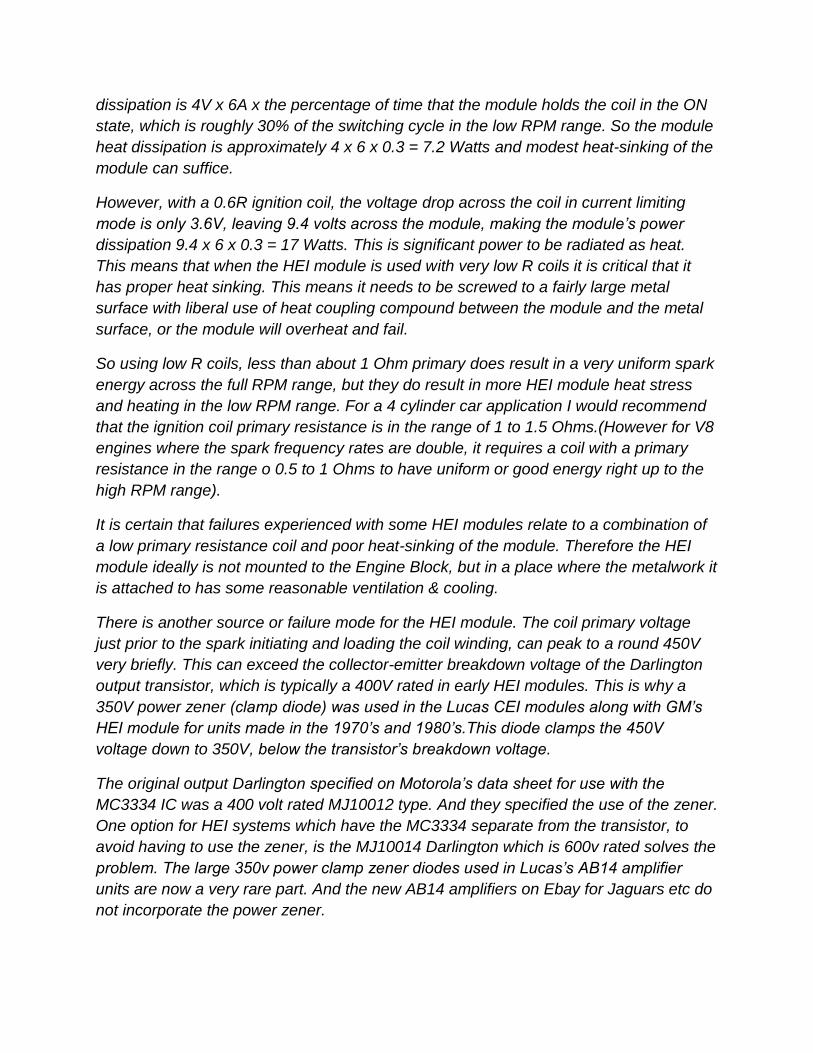
I had the original 25D distributor from the TR4A, which had a perforated diaphragm, but
I realised it would have an ideal spring and metal slug inside. So this unit was opened
up (by machining away its folded over lip) to retrieved the spring and slug.The idea
being to fit this spring & slug to a 45D style vacuum unit with a fresh diaphragm. The
photo below shows the disassembled 25D vacuum unit. (Of note the reason why the
membrane was perforated was that the rubberised fabric had dried out and the rubber
flaked away as hard particles, leaving porous fabric in many places).

To reassemble this as a unit suitable for a 45D or 45DM4 style distributor a donor 45D
vacuum unit was used so as to retain its housing and its diaphragm and actuator arm.
Sixteen 2.0 mm holes were drilled and a small punch made from some brass tubing to
punch 1.5mm holes on the diaphragm perimeter. The photos below show this:
The unit was then reassembled (after painting the front cover) to create a 2-6-3 unit
which would mate to the 45DM4 distributor:

The method shown works well and gasket cement was not required for a perfect seal,
but one needs to be very patient placing the holes. This is why in most cases it would
be better to employ the services of a company with the tools to unfold and re-close the
crimped part of the vacuum canister. Still the unit when created as above does have the
correct screw fitting for the vacuum advance connection, rather than the smooth spigot
seen on 45D series vacuum units.
As noted from the above, this method to convert a vacuum advancer to new specs has
a somewhat “Frankensteinian” look to it. Fortunately one company has developed the
high tech tools required to unfold and refold the lip of the advancer. The photo of one of
these is calibrated to a 2-6-3 unit shown below which was prepared by Peter Collins at

Quality rebuilds in my old home city of Auckland. Not surprising really, remember that
the Kiwis designed the Hamiliton Jet.

The final photo shows that once the distributor was complete, it has been relabelled as
it could be confusing in the future if it was not known that the particular 45DM4 had
been modified:
ALERT: One thing to be aware of, there are two types of reluctors fitted to 45DM4
distributors, most are of the high resistance and high inductance variety (3.3k & 2.42H)
suited to driving HEI modules. There is one type that is not suitable with a 300 Ohm coil
as its output voltage is too low because it has too few turns:

The unsuitable reluctor units have a longer cable, about 8” long compared to the approx
4” long cables of the correct reluctor units so they are easy to spot. The unsuitable ones
appear to have been used in Sunbeam cars and have 417##A code numbers. The
Sunbeams must have had a different ignition amplifier made by Lucas and not one with
the GM HEI modules inside it, I’m guessing.
What happens if the wrong reluctor unit is used with the HEI module?
Due to the fact the output voltage amplitude is considerably lower the dwell time in the
lower RPM ranges is far too short. This results in a very unusual Spark Energy vs RPM
profile shown below:
( I have published the above result because I have seen on an internet forum the wrong
kind of reluctor type 45DM4 combined with an HEI module. Without a spark energy
meter, the person using it might not know this was happening. Fortunately a Spark
Energy Meter is now published and becoming available in Silicon Chip magazine, see
Feb 2015 issue of Silicon Chip- note: I have no financial interest in the sales of these
meter kits)

SPARK ENERGY RECORDINGS HEI VS ASSORTED SYSTEMS:
The following graph is a spark energy recording (mJ per spark) of a reluctor driven
45DM4 HEI system with the Bosch GT40RT (1.5Ohm) transformer ignition coil and the
Bosch MEC723A which is a 1.1 Ohm primary transformer coil similar to the GT40RT.
The standard Kettering system energies measured for a typical 3 Ohm canister ignition
oil style coil(blue) and for a 3 Ohm transformer style coil GT40T is shown (green) & for
the GT40RT1.5 Ohm transformer coil (pink) with a 1.5 Ohm series resistor:
(Of note: The above graphs also shows that simply going from a standard oil coil to a
transformer version of a standard 3 Ohm ignition coil, in the Kettering system, results in
an improvement in spark energy at the low rpm range only. This is due to the higher
primary inductance and therefore more stored energy if the coil current profile has time
to level off. However less spark energy at the high rpm range because the transformer
coil has a higher primary inductance and therefore its L/R ratio or “time constant” is a

little longer than the standard oil style coil and the current doesn’t climb to a very high
value per cycle prior to the spark)
The spark energy results for standard Kettering (60 Degrees dwell) and a standard 3
Ohm primary coils are above shown in blue & green. The GT40RT (1.5 ohm coil)
operating in standard Kettering with the recommended 1.5 Ohm ballast resistor is
shown in pink, so as to compare these with the HEI recordings. These standard
Kettering spark energy results are nearly exactly the same as for electronically assisted
Kettering, such as with a distributor insert with rotating magnets, or a contact breaker
with a transistor amplifier, although sometimes the energy can in fact be even little lower
with the inserts/modules because the output transistor in them, typically a Darlington,
has about a 1 volt voltage drop which is higher than a contact breaker’s voltage drop.
Why do lower primary resistance ignition coils give higher spark energy outputs
when combined with the HEI module?
I felt this should have a satisfactory explanation because on the face of it, even for
those readers who are aware of the basic physics for a circuit containing inductance L,
resistance R connected across a battery, the answers might seem counter intuitive.
The following diagram shows how a current builds up with time in an ignition coil
primary circuit when it is connected across a 12V battery. The resistance is the
resistance of the ignition coil primary and wiring resistances are ignored:
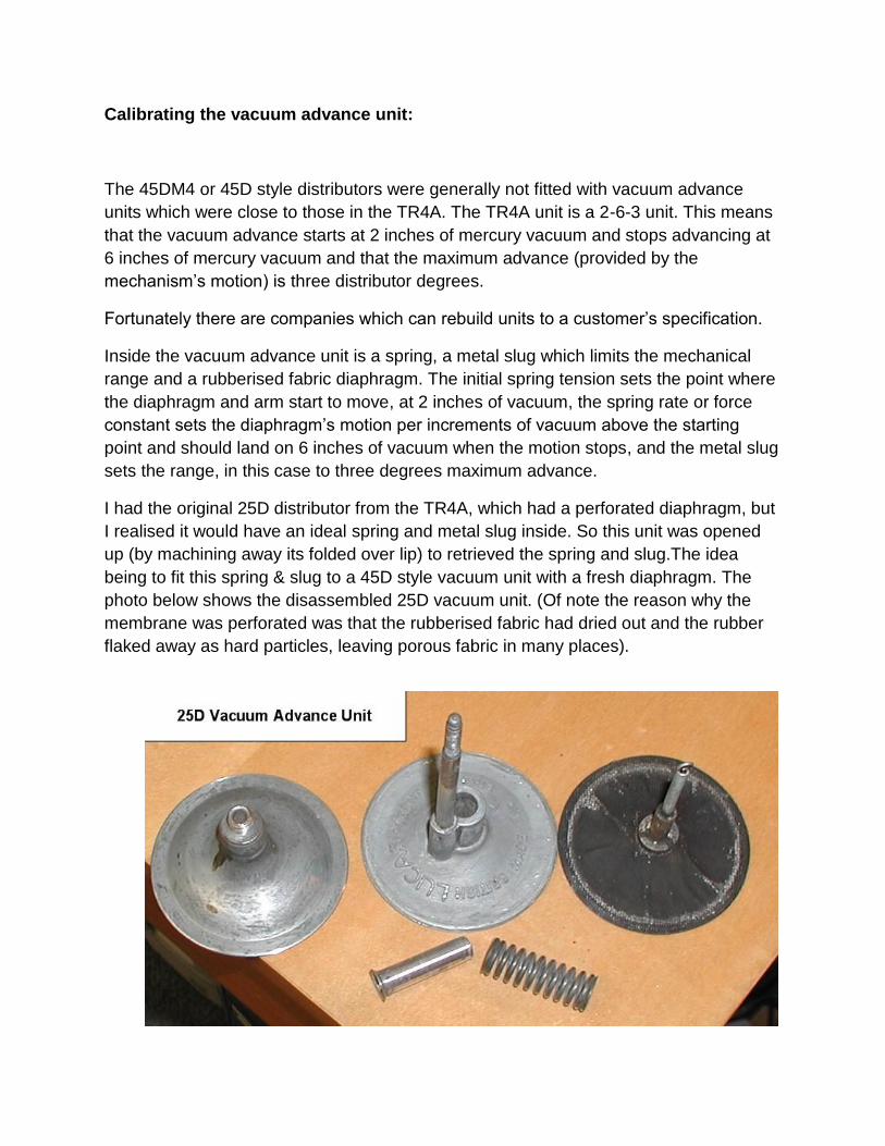
The current rises with an “inverted exponential” format, levelling off with time. The
equation which describes this process is:
I(t) =
(1 - e
-t.R/L)
Where V is the applied voltage, I is the current at any time t, R the coil’s resistance and
L the coil’s inductance.
(Also it is worth noting that the stored magnetic field energy at any time in the coil’s core
is proportional the square of the current value at that time and directly proportional to
the inductance value)
After a while the value inside the brackets of the equation above approaches a value of
1, so that the current simply settles on V/R. For a 13V supply and a 3 Ohm coil, the
current therefore settles on 4.33A. The circuit’s “Time Constant” is the time it takes for
the current to rise to 63% of its maximum value (in this case 4.33A) and it has the value
of L/R or the coil’s inductance divided by the coils resistance. A longer time constant
means that the current will rise to any value more slowly.
So right away here it would appear on the face of it that lowering a coil’s resistance
should result in a longer time constant and therefore a slower rise in current with
time. However, it turns out, due to two other factors, in practice this is not the case:
Firstly the lower primary resistance coils (say in the range of 0.5 Ohms to 1.5 Ohms)
also have lower primary inductance than their 3 Ohm counterparts which helps return
the time constant or L/R ratio closer to a similar value to the 3 Ohm case and due to the
lower primary resistance the potential maximum current is much higher than the 3 Ohm
coil case, so the rate of rise of current with time ends up higher. For example 13V
applied across a 1.5A coil would settle on 8.66 Amps. (In practice it doesn’t get to that
because the 6A current limiter in the HEI module steps in).
So the best way to explain this is with the following examples of common ignition coils
run in a Spice simulator, seeing how quickly they can rise to some value, 2 Amps is
used in the examples:
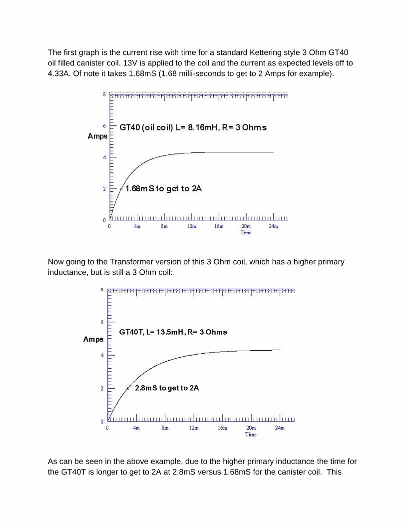
The first graph is the current rise with time for a standard Kettering style 3 Ohm GT40
oil filled canister coil. 13V is applied to the coil and the current as expected levels off to
4.33A. Of note it takes 1.68mS (1.68 milli-seconds to get to 2 Amps for example).
Now going to the Transformer version of this 3 Ohm coil, which has a higher primary
inductance, but is still a 3 Ohm coil:
As can be seen in the above example, due to the higher primary inductance the time for
the GT40T is longer to get to 2A at 2.8mS versus 1.68mS for the canister coil. This

behaviour explains why the GT40T is superior in the low RPM range to the plain GT40
canister coil because the stored energy is 13.5/8.16 higher. However, at the high RPM
range, due to the slower rise time the GT40T is inferior to the GT40 coil because the
current rises to a lower value in the short allowed time.
Moving on to the lower primary resistance coils. Firstly the 1.5 Ohm primary GT40RT
takes 4.33mS to get to 6 Amps (the level that an HEI module limits at) and rises to 2A in
close to one milli-second vs 1.68mS for the 3 Ohm canister coil:
The MEC723 coil, with a 1.1 Ohm primary (and a similar inductance to the GT40RT)
takes less time to get to 6A than the 1.5R coil and still close to 1mS to get to 2 Amps:

So the lower primary resistance coils can climb to any current more quickly than a
higher primary resistance coil. This includes climbing to the 6 Amp threshold limit for the
HEI module. This gives them higher spark energies in the high RPM ranges where “coil
charging time” is limited, especially in the case of V8 motors. However, as noted above,
the lower primary resistance coils place more heat stress on the HEI module in the low
RPM ranges where the module spends more time in current limiting mode.
(In addition, it should also be noted that a standard oil filled canister 3 Ohm ignition coil
such as a GT40, has a secondary DC coil resistance of 17.5k Ohms, and the GT40RT
coil has a secondary DC resistance of 8.46k Ohms. Resistance in the secondary wastes
or dissipates energy during the spark time. So does spark plug resistance, but spark
plug resistance is favourable to suppress very high initial peak currents at spark
formation and therefore suppress radio interference and counter spark plug erosion. So
5k resistor spark plugs are always a good idea).
Therefore in summary, we can now properly answer the question:
1) Why does the reluctor driven HEI module and 1.5 Ohm primary ignition coil such as
the GT40RT deliver about twice the energy per spark (both in the high and low RPM
range) compared to a standard 3 Ohm canister ignition coil regardless of whether the 3
Ohm canister coil is driven by a contact breaker or electronic module insert in the
distributor?
ANSWER:
In the low RPM range; the HEI module raises the 1.5 Ohm coil primary current to 6
amps compared to the 3 Ohm coil at around 4.33 Amps (running of 13V), therefore the
stored energy in the 1.5 Ohm coil could be expected to be about (6/4.33)squared or
about 1.92 times higher, that is if the coils had the same inductance. This is because
the stored energy is proportional to the square of the current. However the inductance
of the 1.5 Ohm coil is 5.48mH compared to 8.16mH for the canister coil, so one could
then expect the stored energy to be 5.48/8.16 = 0.67 times lower, since the stored
energy is linearly proportional to the coil’s inductance value. However the secondary
resistance of the 3 Ohm canister coil is 17.5k and that of the 1.5 Ohm GT40RT coil is
8.46k and assuming 5k resistor spark plugs are being used in the car (as they are in the
input to the spark energy meter) then the two total secondary load resistances are 22.5k

and 13.46k, making the ratio 22.5/13.46 = 1.67 better for the GT40RT, since the
resistances dissipate or waste energy during the spark time.
So the product of these factors is 1.92 x 0.67 x 1.67 = 2.15
Therefore, on approximate calculation, the 1.5 Ohm GT40RT coil and HEI system
should have roughly 2.15 times the spark energy as the standard 3 Ohm canister coil in
the low RPM range. The exact low rpm measurement shows 36mJ per spark for the
canister coil and 65mJ per spark for the 1.5 Ohm GT40RT coil & HEI system which is
1.8 times higher, close to the value of 2.15 calculated above.
In the high RPM range; the rate of rise of current with time for the 1.5 Ohm coil is only
about 1mS to get to 2 Amps for example, however it is much longer for the 3 Ohm
canister coil at about 1.68mS. So the stored energy would be expected to be roughly
1.68(squared) = 2.8 times higher for the 1.5 Ohm coil at the high RPM end where the
time for coil charging was limited (assuming a rough linear approximation for the early
rise in current which is reasonable looking at the graphs). So applying the inductance
ratios and resistance ratios too, then the 1.5 Ohm coil could be expected to be; 2.8 x
0.67 x 1.67 = 3 times better at the high rpm end for the GT40RT-HEI system.
The exact measurements show the spark energy is 20mJ per spark at 6000 RPM for
the 3 Ohm canister coil, and 38mJ per spark for the 1.5 Ohm coil and the HEI system at
6000RPM = 1.9 times better. Possibly the spark time limitation of around 1mS may
slightly limit the energy at the high RPM range in practice.
Conclusion:
No existing auto ignition system beats reluctor- HEI for spark energy across the full
RPM range. In addition it runs the ignition coil cooler at the low rpm range with dwell
time limiting. It doesn’t cook up the coil if the ignition is left on without the motor running.
Both these features extend ignition coil life. It eliminates contact breaker issues. Also it
provides good spark energy at low battery voltages during cranking. Reluctor-HEI
produces about twice as much spark energy across the full rpm range as a conventional
3 Ohm coil, electronically assisted by distributor inserts/modules or not. This is because
the inserts/modules neither raise the coil’s maximum current to a higher value nor can
they increase the rate of rise of coil current with time, because these parameters are set
by the ignition coil properties, not the insert/module type.
While it is true that the spark energy of a system, measured into a dummy load, is only
one possible measurement of an ignition system's capabilities, it is a very good guide to

the ignition system's performance. Spark peak power for example is thought to be a
very important parameter as it relates to the spark's temperature and therefore the
spark's ability to ignite fuel. Of note though, in other spark generating systems such as
those used in rocket motors (Exciter Systems) by NASA; NASA have used spark energy
recordings to characterise Exciter units for that application.
If a particular spark generating system is characterised and documented for energy
output, it is very easy to tell on testing if the unit has become compromised (partially
damaged) and has reduced output compared to its standard specifications. The only
trouble here is that manufacturers of aftermarket auto ignition systems rarely publish
energy recordings on their apparatus and some may not even know the exact energy
characteristics as they have never been properly measured. That leaves the enthusiast
to measure and document their own systems.
One other important feature of the ignition system is its open circuit (or unloaded) peak
output voltage. This is because there must be enough voltage to strike the spark
(usually greater than 15kV) initially, regardless of the amount of spark energy in the
spark burn time. Also the voltage cannot be too high, for example over 40kV as this can
compromise insulation. This measurement requires a special type of high voltage probe
which is frequency compensated (see www.worldphaco.net for the design and theory
behind such a probe). The peak voltage is largely determined by the ignition coil's turns
ratio.
There has been talk since the dawn of CDI systems that the voltage rise time, prior to
the spark starting is very important. The argument being that a slower or longer rise
time dissipates more energy as heat in a fouled spark plug which effectively has parallel
resistance. The coil's secondary voltage rise time, with a CDI or MDI system is limited
by the ignition coil's secondary winding self capacitance, inductance and resistance, so
there is a slowing of the secondary voltage rise time despite the near instantaneous
conduction of the SCR on the primary side in the case of CDI systems.
The fastest secondary voltage rise time I have documented for any CDI system was
from a Thyratron controlled CDI with a special low turns ratio and low capacitance
ignition coil. It was in the order of one to two uS to get to 40kV.Typically though most
CDI's that use standard ignition coils and have capacitors charged to 400V or
thereabouts (SCR types such as the Delta 10B) take about 7uS to get the secondary
voltage to 10kV for example. Its about 20uS to get to 10kV for MDI with the same coil
(and a contact breaker capacitor tuning the primary-see below).
We could compare CDI to an MDI system (with an identical ignition coil) for illustrative
purposes. And we can consider a fouled spark plug with a resistance of 100k Ohms and

measure the secondary voltage rise to say 10kV (where a spark would normally strike in
most cases).This test is done with a frequency compensated high voltage probe.
CDI vs Magnetic discharge ignition (MDI) for high voltage rise times and the ability to
deal with fouled spark plugs:
A formal analysis is now finally available on this topic, see:
www.worldphaco.net for the article Capacitive Discharge ignition and Magnetic
Discharge ignition, the high voltage rise time and fouled plug issue.
The bottom line is that modern transistor driver systems with zener high voltage
clamping on the transistor generate near identical high voltage rise times compared to
CDI. In fact, for any given ignition coil, the high voltage rise time is identical when the
zener clamping voltage is equal to the charging voltage of the discharge capacitor in the
CDI unit. (they are normally both around 400v)
In addition each system CDI & transistorised MDI loaded down with a dummy fouled
spark plug also have a near identical rise time.
However CDI does have a more rapid high voltage rise time than conventional Kettering
MDI where there is a 0.2uF capacitor on the coil primary circuit. This is consistent with
historical remarks from the 1960’s era.
It is also true that a bench test of an ignition system, with an energy meter and testing
off load output voltage parameters etc, is not exactly the same situation as the ignition
system operating in actual use, because of the variable combustion chamber conditions
and spark properties there. However equivalent spark energy testing into zener dummy
loads still provides a good guide to ignition system performance. It allows relative
measurements between different types of ignition systems in a controlled manner.
For example, all power generating system apparatus, those for radio frequencies, audio
frequencies, DC or AC power generation are all tested and characterised into fixed
dummy loads. These are the mainstay of scientific analysis of energy generating
systems. The logical assumption is that performance in use, with variable types of
loads, is well correlated with the performance with dummy loads. There is no logical
reason why the same rules do not apply to spark generating apparatus. And there in lies
the utility of a spark energy meter. For the home enthusiast at least, spark energy
meters for automotive work have not been readily available until now.(See Silicon Chip,
Feb 2015). So with this meter an enthusiast can now check the spark generating
systems in their cars and compare it with other systems.
************************************************************************************************


![WenQuanYi Micro Hei [Scale=0.9]WenQuanYi Micro Hei Mono](https://img.dokumen.tips/doc/110x75/61d6cb71438ad45b233ace00/wenquanyi-micro-hei-scale09wenquanyi-micro-hei-mono-.jpg)