Embed Size (px)
Citation preview

Customised Solutions
grundfos induStry

2322
NBG/NKG PUMPSMix and match to create theideal pump for the job at hand
nB/n
BG/n
K/nKG
– SinG
LE-StAGE En
d-Su
CtiOn
PuM
P

2524
Solution description Photo
AtEX approved A full range of special explosion-proof and dust ignition-proof motors is available with ATEX approved pumps.
MGE motors The Grundfos MGE motor with integrated frequency converter can operate at different speeds in order to optimise pump performance to the application:
Low speed, to obtain e.g.- gentle handling of the liquid- pumping at low NPSH level- reduced noise emission
Oversynchronous speed, to obtain e.g.- more flow and head on a given pump size- compact physical size
The advanced control can measure and adapt to special applications, e.g.:
- Extended protection of process- Extended protection of pump and drive- Pump performance curve adjusted to match
individual applications
Standard MGE motors have built-in motor protection, pump monitoring, and on-board regulator and sensor supply for control of primary process. If special control is required, the MGE can be equipped with extended I/O cards and BUS connection. Customised software and add-on hardware can be tailored to match special demands.
The MGE motor can be controlled by a variety of interfaces, i.e.
- buttons on the pump- advanced R100 infra-red remote control- standard analogue signals- BUS communication
Heating units Anti-condensation heating can be supplied by a built-in heating unit.
Multi-plug Our motors are available with a multi-plug (Harting® plug) according to HAN 10 ES for fast mains connections.
thermal protection
Motors with a built-in bimetallic thermal protector (PTO) or a temperature depending resistance (PTC) are available.
Solution description Photo
curus approval
Grundfos motors are available with the cURus approval covering USA and Canada.
Dual frequency: 50 Hz: 3 x 208-230/460 V 60 Hz: 3 x 400 V
Certificates The Grundfos laboratory is authorised to issue various certificates for motors:- noise- vibration- performance- efficiency
ViK approved motors
VIK approved motors are available according to German industrial electrical standard.
Over or undersize motors
For use where the viscosity or density is different from that of water, installations where the altitude exceeds 1000m or where the ambient temperature is very high.
Special voltage A wide range of supply voltages within three-phase as well as dual voltage can be supplied.
Enclosure class Enclosure class IP 55 is standard on Grundfos motors. Enclosure class IP 65, IP 54 and IP 44 are available as options.
nB/n
BG/n
K/nKG
– SinG
LE-StAGE En
d-Su
CtiOn
PuM
P
Grundfos Blueflux® technology represents the best from Grundfos within energy effi-cient motors and variable frequency drives.
Products with Grundfos Blueflux® label either meet or exceed international legisla-tion regarding motor efficiency.
The motors are available in a variety of configurations to meet the demands of the pumping environment and/or the pumped liquid itself.
What follows is an overview of some of the most common motor variants offered by Grundfos. However, the overview covers only a fragment of the total motor range. Please do not hesitate to contact Grundfos if your requirements are not covered by the overview.
• Special supply voltages
• Extreme operating conditions
• Special motor protection
• Specific approval
• Special motor design
Motors
60 Hz3~MOT MG 90SA2-24FF165-C2
Eff. %80.5-82n 3440-3500 min-1
CL F IP 55 0346DE 6305.2Z.C4 NDE 6205.2Z.C3
P 1.50 kW2
U 220-277D/380-480Y VI 5.70-5.00/3.30-2.90 AI 6.30-5.35/3.65-3.10 A
cos 0.89-0.78
1/1
max
8580
7906
No 85807906

2726
Extreme liquids call for extreme measures. Most NBG/NKG pumps are used for watery liquids at temperatures below 120°C and pressures lower than 16 bar. When liquids go beyond these limits, special shaft seal solutions are required to guarantee reliable operation.
What follows is an overview of some of the most common shaft seal variants for the NBG/NKG range offered by Grundfos. However, the overview covers only a frag-ment of the total shaft seal range. Please do not hesitate to contact Grundfos if your re-quirements are not covered by the overview.
• Aggressive or corrosive liquids
• Abrasive liquids
• Poisonous and/or explosive liquids
• High-viscosity and/or sticky liquids
• Extraordinary high pressure
• Extraordinary high or low temperature
Shaft seals
nB/n
BG/n
K/nKG
– SinG
LE-StAGE En
d-Su
CtiOn
PuM
P
Solution description
double shaft sealBack-to-back
For applications involving dangerous, flammable, or very abrasive liquids, a double shaft seal fitted back-to-back in a pressure chamber is available. The pressure in the chamber must be higher than the pump pressure to prevent leakage.
The barrier fluid pressure can be supplied by either a Grundfos dosing pump arrangement (up to 16 bar) or an intensifier for pressure requirements up to 25 bar.
double shaft seal tandem
For applications involving a high risk of crystallisation (e.g. sugar solutions) or hardening (e.g. oil or paint) as well as pumps handling vacuum, special double shaft seals are available.
Grundfos offers a quenching fluid system for flushing of shaft seals.
double shaft sealtandem or Back-to-back
For applications mentioned above a cartridge seal operating either as a tandem seal or as a back-to-back seal is also available.
Solution description
Shaft seal variants
Grundfos offers a wide range of balanced and unbalanced shaft seals, non-cartridge and cartridge seals. These include several seal face combinations that can handle almost any industrial liquid.
rubber materials
Different combinations of O-rings in shaft seals and in the pump are possible in order to adapt to the specific application. Special rubber types such as FXM (Flouraz®), FFKM (Kalrez®), and HNBR are available where the liquid may dam-age standard O-ring materials such as EPDM, FKM and Viton®.
Stuffing box The stuffing box is an alternative for remote applications where the mechani-cal shaft seal will quickly wear out. Three types are available: without cooling, with internal cooling from the pump, with external cooling.

2928
All the made-to-stock NBG/NKG pump modules can handle the most demanding of liquids and pressures – and be adjustable to virtually any requirement. Of course, the modules can be combined in multiple ways making it possible for us to provide you with a pump solution that matches your specific needs. NBG/NKG pumps come in many flow sizes and various grades of corrosion-resist-ant stainless steel.
What follows is an overview of some of the most common NBG/NKG pump variants offered by Grundfos. However, the overview covers only a fragment of the total pump range. Please do not hesitate to contact Grundfos if your requirements are not cov-ered by the overview.
• High inlet pressure
• High-pressure pump systems required
(up to 25 bar)
• Pumping of gas or particle-entrained
liquids
• Pumping of high-viscosity or sticky liquids
• Vertical pump mounting
• reduced silicon content in pump
• Special materials required
Pump modules
nB/n
BG/n
K/nKG
– SinG
LE-StAGE En
d-Su
CtiOn
PuM
P
Solution description Photo
Housing material
NBG/NKG pump housings are available in three material variants – cast iron and two different stainless steel grades, covering everything from clean water to chemical applications.
impeller material
With the choice of cast iron, bronze or stainlesssteel impellers, the pump can be fully adaptedto any pumped liquid.
Optimised hydraulics of impeller and pumphousing provide outstanding efficiencies.
Wear ring material
The complete pump range is supplied with replaceable wear rings. The wear ring material is matched to the impeller to achieve best possible sealing and wear properties.
Shaft material To provide a very long life and good serviceability of the pump, the wetted part of the shaft is always in stainless steel. Three grades are available: 1.4034, 1.4401, 1.4462.
rubber materials
Different combinations of O-rings in the pump are possible in order to adapt to the specific application. Special rubber types such as FXM (Flouraz®), FFKM (Kalrez®), HNBR and FEPS are available where the liquid may damage stand-ard O-ring materials such as EPDM, FKM and Viton®.
Couplings For NKG pumps two couplings are available: the standard coupling and the spacer coupling.
The spacer coupling provides supreme service-ability.
Solution description Photo
High inlet pressure
For applications with extremely high inlet pressure, a heavy-duty bearing construction is necessary to counterhold the shaft.
Flange connections
Flange connections are according to EN 1092-2 and AS (PN16).
Most stainless steel pumps are available with loose flanges rated for 16, 25 or 40 bar.
Bearing monitoring
Unexpected downtime for repairs usually causes major production losses. This can be avoided by having bearing monitoring devices installed in the bearing bracket. These give continuous information about the bearing condition so that repairs can be scheduled for an appropriate time.
SPM (shock pulse measurement) fittings are fitted as standard in the heavy-duty bearing bracket. Fitting of Pt100 sensors is an option.
Vertical mounting
Certain situations require the pumps to be mounted vertically.
The NBG pumps can be designed to fit installations with limited width, vehicles, ships, etc.
Bare shaft pump
For applications in remote areas or mobile applications where electric power is not available, bare pumps powered by e.g. diesel engine or steam turbine can be supplied.
Silicon reduced pump
For applications where paint wetting impairment substances must not be present, a silicone reduced pump can be used. The silicon reduced pump is assembled using silicone-free components, lubrication, shaft seal, and O-rings.
The product will be performance tested in the normal production test equipment.
3130
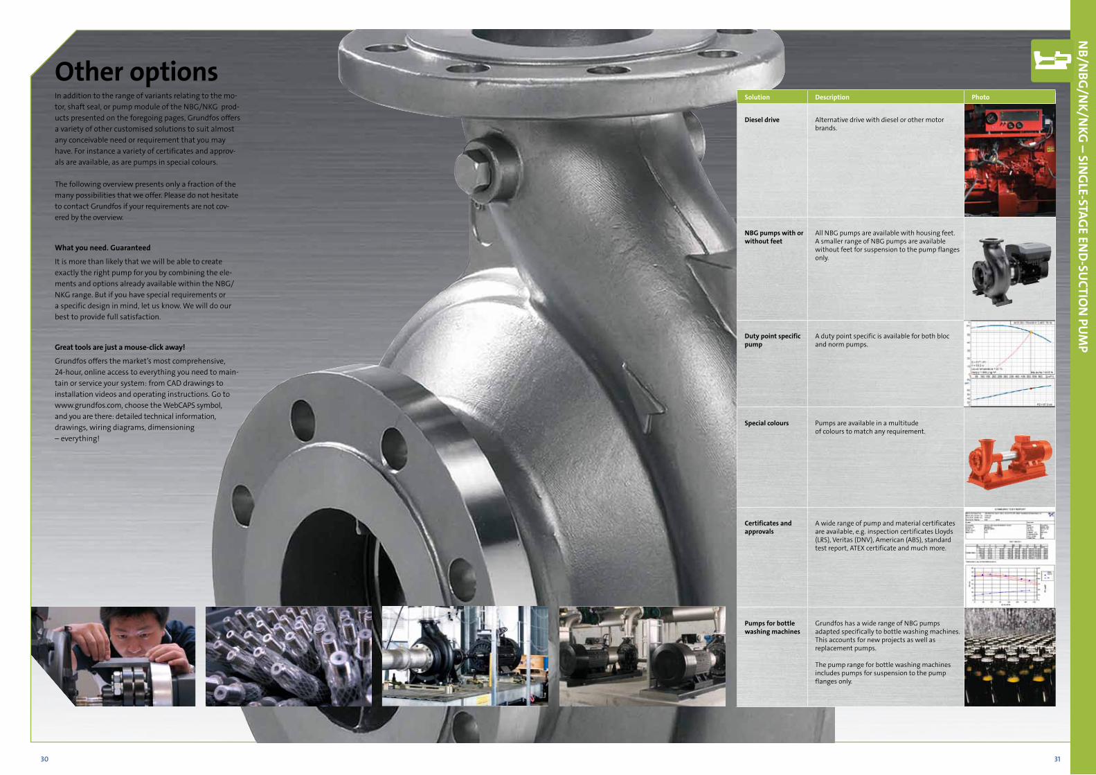
In addition to the range of variants relating to the mo-tor, shaft seal, or pump module of the NBG/NKG prod-ucts presented on the foregoing pages, Grundfos offers a variety of other customised solutions to suit almost any conceivable need or requirement that you may have. For instance a variety of certificates and approv-als are available, as are pumps in special colours.
The following overview presents only a fraction of the many possibilities that we offer. Please do not hesitate to contact Grundfos if your requirements are not cov-ered by the overview.
What you need. Guaranteed
It is more than likely that we will be able to create exactly the right pump for you by combining the ele-ments and options already available within the NBG/NKG range. But if you have special requirements or a specific design in mind, let us know. We will do our best to provide full satisfaction.
Great tools are just a mouse-click away!
Grundfos offers the market’s most comprehensive, 24-hour, online access to everything you need to main-tain or service your system: from CAD drawings to installation videos and operating instructions. Go to www.grundfos.com, choose the WebCAPS symbol, and you are there: detailed technical information, drawings, wiring diagrams, dimensioning – everything!
Other options
nB/n
BG/n
K/nKG
– SinG
LE-StAGE En
d-Su
CtiOn
PuM
P
Solution description Photo
diesel drive Alternative drive with diesel or other motor brands.
nBG pumps with or without feet
All NBG pumps are available with housing feet.A smaller range of NBG pumps are available without feet for suspension to the pump flanges only.
duty point specific pump
A duty point specific is available for both bloc and norm pumps.
Special colours Pumps are available in a multitude of colours to match any requirement.
Certificates and approvals
A wide range of pump and material certificates are available, e.g. inspection certificates Lloyds (LRS), Veritas (DNV), American (ABS), standard test report, ATEX certificate and much more.
Pumps for bottle washing machines
Grundfos has a wide range of NBG pumps adapted specifically to bottle washing machines. This accounts for new projects as well as replacement pumps.
The pump range for bottle washing machines includes pumps for suspension to the pump flanges only.

3332
4 6 1010 20 40 60 100100 200 400 600 10001000Q [m³/h]
8
10
15
20
30
40
5060
80
100120
150
200[m]H
NB, NK2-pole, 50 Hz
4 6 10 20 40 60 100 200 400 600 1400Q [m³/h]
2
3
456
810
15
20
30
405060
80100120
[m]H
NB, NK4-pole, 50 Hz
10 20 40 60 100100 200 400 600 10001000Q [m³/h]
2
3
4
56
8
10
15
20
30
40
5060
[m]H
NB, NK6-pole, 50 Hz
4 6 1010 20 40 60 100100 200 400 600 10001000Q [m³/h]
10
15
20
30
40
50
607080
100
120
150
[m]H
NB, NK2-pole, 60 Hz
4 6 10 20 40 60 100 200 400 600 1500Q [m³/h]
456
810
15
20
30
405060
80100120150
200
[m]H
NB, NK4-pole, 60 Hz
10 20 40 60 100100 200 400 600 10001000Q [m³/h]
3
4
56
8
10
15
20
30
40
5060
80
[m]H
NB, NK6-pole, 60 Hz
Performance range nB/nK pumps according to En 733
nB/n
BG/n
K/nKG
– SinG
LE-StAGE En
d-Su
CtiOn
PuM
P

3534
4 6 10 20 40 60 100 200 400 600 1400Q [m³/h]
8
1012
15
20
30
40
50607080
100120
150
200[m]H
NBG, NKG2-pole, 50 Hz
4 6 10 20 40 60 100 200 400 600 1400Q [m³/h]
2
3
456
810
15
20
30
405060
80100120150
[m]H
NBG, NKG4-pole, 50 Hz
10 20 40 60 100100 200 400 600 10001000Q [m³/h]
2
3
4
5678
10
15
20
30
40
5060
[m]H
NBG, NKG6-pole, 50 Hz
4 6 1010 20 40 60 100100 200 400 600 10001000Q [m³/h]
10
15
20
30
40
50
607080
100
120
150
[m]H
NBG, NKG2-pole, 60 Hz
4 6 10 20 40 60 100 200 400 600 1500Q [m³/h]
456
810
15
20
30
405060
80100120150
200
[m]H
NBG, NKG4-pole, 60 Hz
10 15 20 40 60 100100 200 400 600 10001000Q [m³/h]
3
4
5678
10
15
20
30
40
50607080
100[m]H
NBG, NKG6-pole, 60 Hz
Performance range nBG/nKG pumps according to iSO 2858
nB/n
BG/n
K/nKG
– SinG
LE-StAGE En
d-Su
CtiOn
PuM
P

3736
Pump size
nBG nKG Cast iron pump Stainless steel pumpCastiron
pump
Stainless steel
pump
Castiron
pump
Stainless steel
pump
Flange rating
Flange standard
Flange rating
Flange standard
EN-G
JL-2
50
1.440
8
1.451
7
Sing
le m
ech.
seal
Dou
ble
mec
h. se
al
Cart
ridge
seal
- si
ngle
/dou
ble
Pum
p w
ithou
t fee
t
Pum
p w
ith su
ppor
t blo
cks
Base
fram
e
EN-G
JL-2
50
1.440
8
1.451
7
Sing
le m
ech.
seal
Dou
ble
mec
h. se
al
Cart
ridge
seal
- si
ngle
/dou
ble
Stuf
fing
box
Hea
vy d
uty
bear
ing
brac
ket
Bear
ing
mon
itorin
g
PN 10
PN 16
DIN
(cod
e F)
ANSI
(cod
e G
)
JIS (c
ode
J)
PN 16
PN 2
5
DIN
(cod
e F)
DIN
(cod
e F)
ANSI
(cod
e G
)
JIS (c
ode
J)
50-32-125.1 x x x x - - - - - x x x x x x x x x F F x - - F F F x x x50-32-160.1 x x x x - - - - - x x x x x x x x x F F x - - F F F x x x50-32-200.1 x x x x - - - - - x x x x x x x x x F F x - - F F F x x x50-32-125 x x x x - - - x - x x x x x x x x x F F x - - F F F x x x50-32-160 x x x x - - - x - x x x x x x x x x F F x - - F F F x x x50-32-200 x x x x - - - x - x x x x x x x x x F F x - - F F F x x x50-32-250 x x x x - - - x - x x x x x x - x x F F x - - F F F x x x65-50-125 x x x x - - - x - x x x x x x x x x F F x - - L L L x x x65-50-160 x x x x - - - x - x x x x x x x x x F F x - - L L L x x x65-40-200 x x x x - - - x - x x x x x x x x x F F x - - L L L x x x65-40-250 x x x x - - - x - x x x x x x - x x F F x - - L L L x x x65-40-315 x x x x - - - x x x x x x x x - x x F F x - - L L L x x x80-65-125 x x x x - - - x - x x x x x x x x x F F x - - L L L x x x80-65-160 x x x x - - x x - x x x x x x x x x F F x - - L L L x x x80-50-200 x x x x - - x x - x x x x x x x x x F F x - - L L L x x x80-50-250 x x x x - - x x - x x x x x x - x x F F x - - L L L x x x80-50-315 x x x x - - - x x x x x x x x - x x F F x - - L L L x x x100-80-125 x x x x - - - x - x x x x x x x x x F F x - - L L L x x x100-80-160 x x x x - - x x - x x x x x x - x x F F x - - L L L x x x100-65-200 x x x x - - x x - x x x x x x - x x F F x - - L L L x x x100-65-250 x x x x - - - x x x x x x x x x x x F F x - - L L L x x x100-65-315 x x x x - - - x x x x x x x x - x x F F x - - L L L x x x125-80-160 x x x x - - x x - x x x x x x - x x F F x - - L L L x x x125-80-200 x x x x - - - x x x x x x x x x x x F F x - - L L L x x x125-80-250 x x x x - - - x x x x x x x x x x x F F x - - L L L x x x125-80-315 x x x x - - - x x x x x x x x - x x F F x - - L L L x x x125-80-400 x x x x - - - x x x x x x x x - x x F F x - - L L L x x x125-100-160* x x x x - - - x - x x x x x x - x x F F x - - L L L x x x125-100-200 x x x x - - - x x x x x x x x x x x F F x - - L L L x x x125-100-250 x x x x - - - x x x x x x x x - x x F F x - - L L L x x x125-100-315 x x x x - - - x x x x x x x x - x x F F x - - L L L x x x125-100-400 x x x x - - - x x x x x x x x - x x F F x - - L L L x x x150-125-200 x x x x - - - x x x x x x x x x x x F F x - - L L L x x x150-125-250 x x x x - - - x x x x x x x x - x x F F x - - L L L x x x150-125-315 x x x x - - - x x x x x x x x - x x F F x - - L L L x x x150-125-400 x x x x - - - x x x x x x x x - x x F F x - - L L L x x x150-125-500 x x x x - - - x x x x x x x x - x x F F x - - L L L x x x200-150-200 x x x x - - - x x x x x x x x x x x - F x - - L L L x x x200-150-250 x x x x - - - x x x x x x x x - x x - F x - - L L L x x x200-150-315 x x x x - - - x x x x x x x x - x x - F x - - L L L x x x200-150-400 x x x x - - - x x x x x x x x - x x - F x - - L L L x x x200-150-500 x x x x - - - x x x x x x x x - x x - F x - - L L L x x x250-200-400 x - - x - - - x x x - - x - - - - - - F x - - - - - - - - 250-200-450 x - - x - - - x x x - - x - - - - - - F x - - - - - - - - 300-250-350 x - - x - - - x x x - - x - - - - - - F x - - - - - - - - 300-250-400 x - - x - - - x x x - - x - - - - - - F x - - - - - - - - 300-250-450 x - - x - - - x x x - - x - - - - - - F x - - - - - - - - 300-250-500 x - - x - - - x x x - - x - - - - - - F x - - - - - - - -
1) The max. pressure rating for the pump is 25 bar. 2) The loose flange is cast iron GGG50-EN-GJS-500-7 3) All pump housing sizes can be supplied with feet.
“F=fixed flange L=loose flange 2)”
nB/n
BG/n
K/nKG
– SinG
LE-StAGE En
d-Su
CtiOn
PuM
P
technical data
Pump size
nB nK Cast iron pump Stainless steel pumpCastiron
pump
Stainless steel
pump
Castiron
pump
Stainless steel
pump
Flange rating
Flange standard
Flange rating
Flange standard
EN-G
JL-2
50
1.440
8
1.451
7
Sing
le m
ech.
seal
Dou
ble
mec
h. se
al
Cart
ridge
seal
- si
ngle
/dou
ble
Pum
p ho
usin
g w
ithou
t fee
t 3)
Pum
p w
ith su
ppor
t blo
cks
Base
fram
e
EN-G
JL-2
50
1.440
8
1.451
7
Sing
le m
ech.
seal
Dou
ble
mec
h. se
al
Cart
ridge
seal
- si
ngle
/dou
ble
Stuf
fing
box
Hea
vy d
uty
bear
ing
brac
ket
Bear
ing
mon
itorin
g
PN 10
PN 16
DIN
(cod
e F)
ANSI
(cod
e G
)
JIS (c
ode
J)
PN 10
PN 16
DIN
(cod
e F)
ANSI
(cod
e G
)
JIS (c
ode
J)
32-125.1 x x x x - - - - - x x x x - - x - - F F x - - F F x - - 32-160.1 x x x x - - - - - x x x x - - x - - F F x - - F F x - - 32-200.1 x x x x - - - - - x x x x - - x - - F F x - - F F x - - 32-125 x x x x - - - x - x x x x - - x - - F F x - - F F x - - 32-160 x x x x - - - x - x x x x - - x - - F F x - - F F x - - 32-200 x x x x - - - x - x x x x - - x - - F F x - - F F x - - 32-250* x x x x - - - x - x x x x - - x - - F F x - - F F x - - 40-125 x x x x - - - x - x x x x - - x - - F F x - - F F x - - 40-160 x x x x - - - x - x x x x - - x - - F F x - - F F x - - 40-200 x x x x - - x x - x x x x - - x - - F F x - - F F x - - 40-250 x x x x - - x x - x x x x - - x - - F F x - - F F x - - 40-315* x x x x - - - x x x x x x - - - - - F F x - - F F x - - 50-125 x x x x - - - x - x x x x - - x - - F F x - - F F x - - 50-160 x x x x - - x x - x x x x - - x - - F F x - - F F x - - 50-200 x x x x - - x x - x x x x - - x - - F F x - - F F x - - 50-250 x x x x - - x x - x x x x - - x - - F F x - - F F x - - 50-315* x x x x - - - x x x x x x - - - - - F F x - - F F x - - 65-125 x x x x - - - x - x x x x - - x - - F F x - - F F x - - 65-160 x x x x - - x x - x x x x - - x - - F F x - - F F x - - 65-200 x x x x - - x x - x x x x - - x - - F F x - - F F x - - 65-250 x x x x - - - x x x x x x - - x - - F F x - - F F x - - 65-315 x x x x - - - x x x x x x - - x - - F F x - - F F x - - 80-160 x x x x - - x x - x x x x - - x - - F F x - - F F x - - 80-200 x x x x - - - x x x x x x - - x - - F F x - - F F x - - 80-250 x x x x - - - x x x x x x - - x - - F F x - - F F x - - 80-315 x x x x - - - x x x x x x - - x - - F F x - - F F x - - 80-400* x x x x - - - x x x x x x - - - - - F F x - - F F x - - 100-160* x x x x - - - x - x x x x - - x - - F F x - - L L x - - 100-200 x x x x - - - x x x x x x - - x - - F F x - - L L x - - 100-250 x x x x - - - x x x x x x - - x - - F F x - - L L x - - 100-315 x x x x - - - x x x x x x - - x - - F F x - - L L x - - 100-400 x x x x - - - x x x x x x - - - - - F F x - - L L x - - 125-200 x x x x - - - x x x x x x - - x - - F F x - - L L x - - 125-250 x x x x - - - x x x x x x - - x - - F F x - - L L x - - 125-315 x x x x - - - x x x x x x - - - - - F F x - - L L x - - 125-400 x x x x - - - x x x x x x - - - - - F F x - - L L x - - 125-500 x x x x - - - x x x x x x - - - - - F F x - - L L x - - 150-200 x x x x - - - x x x x x x - - x - - F - x - - L L x - - 150-250 x x x x - - - x x x x x x - - - - - F - x - - L L x - - 150-315 x x x x - - - x x x x x x - - - - - F - x - - L L x - - 150-400 x x x x - - - x x x x x x - - - - - F - x - - L L x - - 150-500 x x x x - - - x x x x x x - - - - - F - x - - L L x - - 200-400 x - - x - - - x x x - - x - - - - - F - x - - - - - - - 200-450 x - - x - - - x x x - - x - - - - - F - x - - - - - - - 250-350 x - - x - - - x x x - - x - - - - - F - x - - - - - - - 250-400 x - - x - - - x x x - - x - - - - - F - x - - - - - - - 250-450 x - - x - - - x x x - - x - - - - - F - x - - - - - - - 250-500 x - - x - - - x x x - - x - - - - - F - x - - - - - - -
* = oversize 2) The loose flange is cast iron GGG50-EN-GJS-500-7 3) All pump housing sizes can be supplied with feet.
“F=fixed flange L=loose flange 2)”

3938
2/3 of all pumps installed today are inefficient and use up to 60% too much energy
Gru
nd
FOS Pu
MP Au
dit
When your existing pump pool is more than five years old, you will probably have big potential for saving money and CO2 in your daily operation.
Save energy, save moneyIt is vital that pump systems are optimised to their full potential. Many pumps waste energy and by optimising or replacing them, huge reductions in CO2 and operational costs can be achieved.
Grundfos Pump AuditTake advantage of the Grundfos Pump Audit. It is a service concept that will, in just a few steps, furnish you with black and white facts about the efficiency of your pump process. The Pump Audit report will enable you to take further steps to optimise your pumps and operations.
Correctly sized, new pumps are more efficient, require longer service intervals and encounter less downtime. What’s more, payback time is usually as little as six months to two years.
Expert teamThe Grundfos Pump Audit team is ready to offer you a thorough in-vestigation of your pump systems. Contact us for more information.
PUMP aUditSaved MoNeyRedUCed C0
2
aPPoiNtMeNt with CoNSUltaNt oN Site iNSPeCtioN diaGNoSiS ReCoMMeNdatioNS
oPtiMiSed PRoCeSSeS

GrundFOS Holding A/SPoul Due Jensens Vej 7DK-8850 BjerringbroTel: +45 87 50 14 00www.grundfos.com
The
nam
e G
rund
fos,
the
Gru
ndfo
s log
o, a
nd b
e th
ink
inno
vate
are
regi
ster
ed tr
adem
arks
ow
ned
by G
rund
fos H
oldi
ng A
/S o
r Gru
ndfo
s A/S
, Den
mar
k. A
ll rig
hts r
eser
ved
wor
ldw
ide.
9791
5212
/Ind
ustr
y/09
12/9
857-
D&
I
Customisation made easyIn order to meet all customer requirements with complete
precision, Grundfos has developed a unique mix-and-match
approach to customised pumps. The elements of the CR and
NBG/NKG ranges can be combined any which way to create
the solution that is exactly right for you.
Grundfos: a pump for every purposeGrundfos offers much more. A complete range of pump
solutions means that all applications – industrial and
domestic – can benefit from the Grundfos touch.
• Heating
• Cooling
• Water Supply
• Wastewater
• Fire Fighting
• Dosing
• Industrial Processes