Embed Size (px)
Citation preview

Customer Advanced Technologies Program Technology Evaluation Report
The OASys
Prepared by
Dave Bisbee, CE
Energy Efficiency & Customer ResSacramento Municipal Ut
December 14, 20
M
earch & Development ility District 05

Contents
Introduction …………………………………………………………………………………….. 1 HVAC 101
Principles of Evaporative Cooling……………………….…………………………..………. 1 Direct Evaporative Cooling Systems……..…………………………………………..……… 2 Indirect-Direct Evaporative Cooling (IDEC) Systems..……………………………..………. 4 A Rough Beginning for IDECs……………………….……………………………..………. 6
Technology Description – OASys…………..……………………………………….………. 7 SMUD Study
Project Description……………………..…………………………………………..……….. 8 Lessons Learned..……..………………..…………………………………………..……….. 8 Monitoring Results……………………..…………………………………………..……….. 10 Customer Survey Results.………………..…………………………………………..……… 12
Building America Study………..…………..……………………………………….……….. 12
Conclusions....……….……………..………………………………………………..………….. 13 References………….…………………………………………………………………………… 14 About the Customer Advanced Technologies Program SMUD’s Customer Advanced Technologies (CAT) program works with customers, researchers and manufacturers to encourage the use and evaluation of new and underutilized technologies. The program provides funding for customers in exchange for monitoring rights. Completed demonstration projects include lighting technologies, light emitting diodes (LEDs), residential building shell construction, indirect-direct evaporative cooling, non-chemical water treatment systems and a wide variety of other technologies. For more program information, please visit: http://www.smud.org/education/cat/index.html

1
Introduction Almost everyone agrees that evaporative cooling systems have tremendous potential to reduce cooling energy requirements in hot-dry climates. However, since conventional evaporative coolers (a.k.a. ‘swamp coolers’) produce moisture-laden air, their acceptance in the market has been limited to consumers who live in hot, dry climates and are willing to accept higher indoor humidity levels in exchange for lower energy and installation costs. In an effort to help overcome this market barrier, a few manufacturers developed indirect-direct evaporative cooling systems (IDECs). IDECs offer increased comfort over swamp coolers and only use a fraction of the energy required by conventional air conditioning systems. However, past efforts to develop this technology have been hampered by reliability issues and have been a source of many comfort-related complaints. For more information, please visit http://www.smud.org/education/cat/index.html and download the report “Operation IDEC Rescue”. The Davis Energy Group is partnering with the Speakman Company to develop and test a new generation of IDECs known as the OASys. The main goal of this project is to develop a more reliable IDEC system by applying lessons learned from previous experiences. SMUD sponsored deployment and testing of five systems for customers who have experienced chronic problems with their existing IDEC systems. This technology report focuses on the basics of evaporative cooling systems and the results of a local OASys demonstration project. HVAC 101 Principles of Evaporative Cooling
Before we look at the OASys, it may be helpful to review some basic principles of evaporative cooling. When air comes into contact with water, some of the water evaporates. This happens because the temperature and the vapor pressure of the water and the air attempt to equalize. As the water molecules become a gas (evaporate), they absorb heat from the surrounding air and lower its temperature. The heat is still present, however; it has just been captured in the form of water vapor within the air (humidity). This phenomena is known as adiabatic cooling and is found throughout nature - lakes, rivers, oceans, anywhere there is water. Today people use evaporative cooling systems for a wide variety of purposes – comfort cooling, manufacturing processes and other applications.
The information, statements, representations, graphs and data presented in this report are provided by SMUD as a service to our customers. SMUD does not endorse products or manufacturers. Mention of any particular product
or manufacturer in this report should not be construed as an implied endorsement.
Some Cool Terms Dry bulb temperature: temperature of air independent of its moisture content. It may be measured by using common thermometers. Wet bulb temperature: the lowest theoretical temperature achievable by evaporating water in a quantity of air at a given dry bulb temperature and humidity level, using only the heat within the air. It is measured by placing a moist piece of fabric over the thermometer and blowing air across it. The air evaporates the water, lowering the temperature on the thermometer to the wet bulb temperature1. Absolute humidity: the amount of water vapor present in air. Relative humidity: the amount of water vapor present in air compared to the maximum amount it could hold. Direct evaporative cooler: system in which the air comes into direct contact with wetted pads before entering the conditioned space. Commonly called swamp coolers. Indirect-direct evaporative cooler (IDEC): system that uses a combination of direct evaporative cooling and an indirect evaporative heat exchanger. Commonly called two-stage evaporative coolers.
2
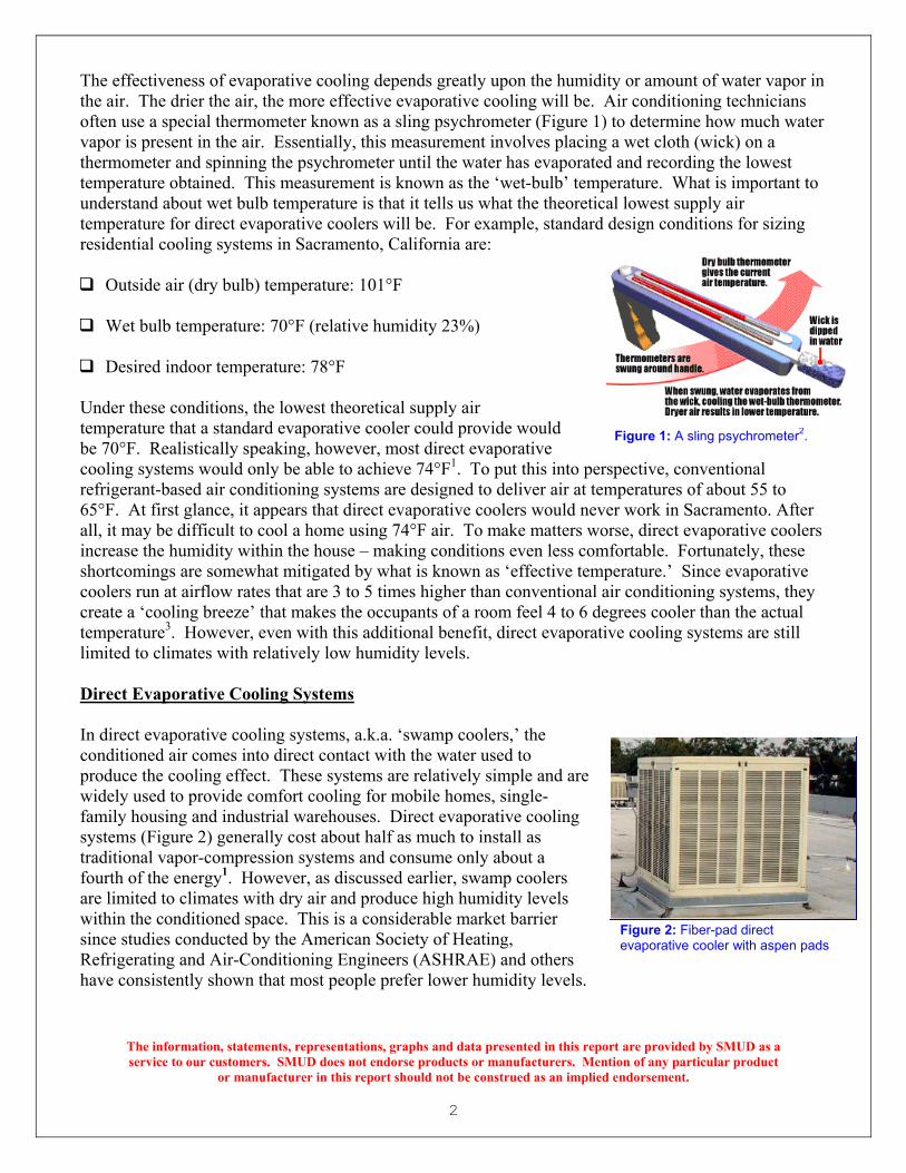
The effectiveness of evaporative cooling depends greatly upon the humidity or amount of water vapor in the air. The drier the air, the more effective evaporative cooling will be. Air conditioning technicians often use a special thermometer known as a sling psychrometer (Figure 1) to determine how much water vapor is present in the air. Essentially, this measurement involves placing a wet cloth (wick) on a thermometer and spinning the psychrometer until the water has evaporated and recording the lowest temperature obtained. This measurement is known as the ‘wet-bulb’ temperature. What is important to understand about wet bulb temperature is that it tells us what the theoretical lowest supply air temperature for direct evaporative coolers will be. For example, standard design conditions for sizing residential cooling systems in Sacramento, California are:
Outside air (dry bulb) temperature: 101°F
Wet bulb temperature: 70°F (relative humidity 23%)
Desired indoor temperature: 78°F
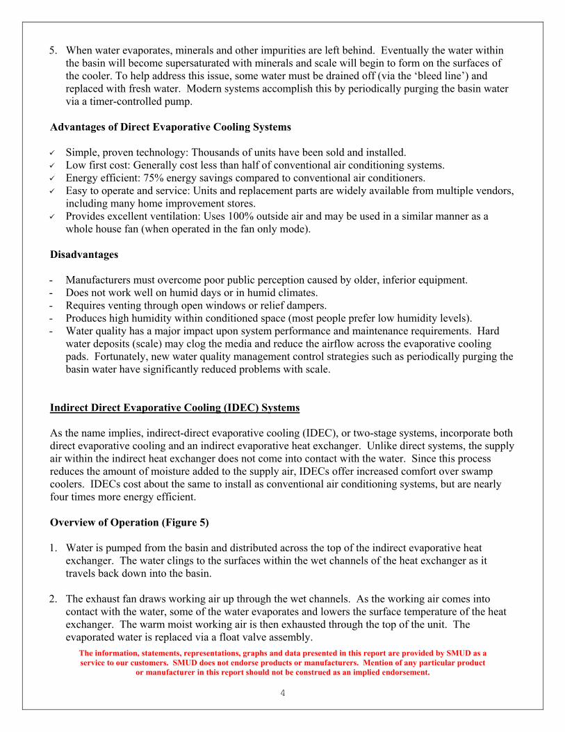
Under these conditions, the lowest theoretical supply air temperature that a standard evaporative cooler could provide would be 70°F. Realistically speaking, however, most direct evaporative cooling systems would only be able to achieve 74°F1. To put this into perefrigerant-based air conditioning systems are designed to deliver air at te65°F. At first glance, it appears that direct evaporative coolers would neall, it may be difficult to cool a home using 74°F air. To make matters wincrease the humidity within the house – making conditions even less comshortcomings are somewhat mitigated by what is known as ‘effective temcoolers run at airflow rates that are 3 to 5 times higher than conventionalcreate a ‘cooling breeze’ that makes the occupants of a room feel 4 to 6 dtemperature3. However, even with this additional benefit, direct evaporalimited to climates with relatively low humidity levels. Direct Evaporative Cooling Systems In direct evaporative cooling systems, a.k.a. ‘swamp coolers,’ the conditioned air comes into direct contact with the water used to produce the cooling effect. These systems are relatively simple and are widely used to provide comfort cooling for mobile homes, single-family housing and industrial warehouses. Direct evaporative cooling systems (Figure 2) generally cost about half as much to install as traditional vapor-compression systems and consume only about a fourth of the energy1. However, as discussed earlier, swamp coolers are limited to climates with dry air and produce high humidity levels within the conditioned space. This is a considerable market barrier since studies conducted by the American Society of Heating, Refrigerating and Air-Conditioning Engineers (ASHRAE) and others have consistently shown that most people prefer lower humidity levels.
The information, statements, representations, graphs and data presented in this repservice to our customers. SMUD does not endorse products or manufacturers. Me
or manufacturer in this report should not be construed as an impli
rspective, conventional mperatures of about 55 to
ver work in Sacramento. After orse, direct evaporative coolers
fortable. Fortunately, these perature.’ Since evaporative
air conditioning systems, they egrees cooler than the actual tive cooling systems are still
ort are provided by SMUD as a ntion of any particular product
ed endorsement.
Figure 2: Fiber-pad direct evaporative cooler with aspen pads
Figure 1: A sling psychrometer2.

There are two basic types of direct evaporative coolers: 1. Fiber pad coolers (shown earlier in Figure 2): The most commonly
used evaporative cooling systems use pads that are made from shredded aspen wood fibers (a.k.a. excelsior) packed within a plastic net. Although synthetic fiber pads are available, they seldom perform as well as high-quality aspen pads. Fiber pads usually range from 1 to 2 inches in thickness. They are disposable and should be replaced every one or two years4.
2. Rigid sheet pad coolers: (Figure 3) This type of cooler, also
known as a ‘single-inlet cooler,’ used to be found only in large commercial applications but is becoming more common in residential applications as well. It uses rigid-sheet pads made from corrugated material that allows air to move through at higher velocities than is possible with aspen pads. Rigid sheet pads are usually 8 or 12 inches thick and have a corrugation pattern that forces water to flood the pad's air inlet side where most of the evaporation of water occurs. They can last for many years if water quality is properly maintained.
Rigid sheet pad coolers are substantially more expensive than fiber pad coolers, but are much more energy efficient and can deliver air that is 5 to 10 degrees cooler than coolers with conventional aspen pads.5
Overview of Operation (Figure 4) 1. Water is pumped from the basin (bottom of
the unit) and distributed across the top of the evaporative cooling pads. Some of the water saturates the pads while the rest falls back down into the basin.
2. The blower draws outside air across the face
of the evaporative cooling pads. When the air comes into contact with the wetted pads, some of the water evaporates and lowers the dry bulb temperature of the air.
3. The blower delivers cool moist air to the conditioned space. Since this air is very humid, evaporative coolers do not use return air ducts. Because of this, the air must ultimately be exhausted through open windows or relief dampers.
4. The evaporated water is replaced via a float valv
The information, statements, representations, graphs anservice to our customers. SMUD does not endorse prod
or manufacturer in this report should no
Figure 3: Direct evaporative cooler with rigid sheet pads5
Figure 4: Diagram of a fiber-pad, direct evaporative cooler
3
e assembly.
d data presented in this report are provided by SMUD as a ucts or manufacturers. Mention of any particular product t be construed as an implied endorsement.
4
The information, statements, representations, graphs and data presented in this report are provided by SMUD as a service to our customers. SMUD does not endorse products or manufacturers. Mention of any particular product
or manufacturer in this report should not be construed as an implied endorsement.
5. When water evaporates, minerals and other impurities are left behind. Eventually the water within the basin will become supersaturated with minerals and scale will begin to form on the surfaces of the cooler. To help address this issue, some water must be drained off (via the ‘bleed line’) and replaced with fresh water. Modern systems accomplish this by periodically purging the basin water via a timer-controlled pump.
Advantages of Direct Evaporative Cooling Systems Simple, proven technology: Thousands of units have been sold and installed. Low first cost: Generally cost less than half of conventional air conditioning systems. Energy efficient: 75% energy savings compared to conventional air conditioners. Easy to operate and service: Units and replacement parts are widely available from multiple vendors,
including many home improvement stores. Provides excellent ventilation: Uses 100% outside air and may be used in a similar manner as a
whole house fan (when operated in the fan only mode). Disadvantages - Manufacturers must overcome poor public perception caused by older, inferior equipment. - Does not work well on humid days or in humid climates. - Requires venting through open windows or relief dampers. - Produces high humidity within conditioned space (most people prefer low humidity levels). - Water quality has a major impact upon system performance and maintenance requirements. Hard
water deposits (scale) may clog the media and reduce the airflow across the evaporative cooling pads. Fortunately, new water quality management control strategies such as periodically purging the basin water have significantly reduced problems with scale.
Indirect Direct Evaporative Cooling (IDEC) Systems As the name implies, indirect-direct evaporative cooling (IDEC), or two-stage systems, incorporate both direct evaporative cooling and an indirect evaporative heat exchanger. Unlike direct systems, the supply air within the indirect heat exchanger does not come into contact with the water. Since this process reduces the amount of moisture added to the supply air, IDECs offer increased comfort over swamp coolers. IDECs cost about the same to install as conventional air conditioning systems, but are nearly four times more energy efficient. Overview of Operation (Figure 5) 1. Water is pumped from the basin and distributed across the top of the indirect evaporative heat
exchanger. The water clings to the surfaces within the wet channels of the heat exchanger as it travels back down into the basin.
2. The exhaust fan draws working air up through the wet channels. As the working air comes into
contact with the water, some of the water evaporates and lowers the surface temperature of the heat exchanger. The warm moist working air is then exhausted through the top of the unit. The evaporated water is replaced via a float valve assembly.

3. T
essin
4. WS
5. Tthd
6. Cno
7. TasthMp
Warm moist air
Evaporative pad
Float valve assembly
Indirect evaporative heat exchanger
Outside air
Indirect Evaporative Cooling Section
Direct Evaporative Cooling Section
Blower compartment
Blower motor
Water circulation pump
Supply air6
2
Exhaust fan
Water bleed lines
1
3
4
Main blower
5
7
Figure 5: Diagram of an indirect-direct evaporative cooler
5
The information, statements, representations, graphs and data presented in this report are provided by SMUD as a service to our customers. SMUD does not endorse products or manufacturers. Mention of any particular product
or manufacturer in this report should not be construed as an implied endorsement.
he main blower draws outside air (supply air) across the face of the indirect evaporative heat xchanger. When the supply air comes into contact with the cool surface of the heat exchanger, ome of its heat is transferred indirectly into the water via the heat exchanger. In other words, the upply air does not come into direct contact with the water. After the supply air passes through the direct heat exchanger, it continues on to the direct evaporative cooling section.
ater is pumped from the basin and distributed across the top of the direct evaporative cooling pads. ome of the water saturates the pads while the rest falls back down into the basin of the unit.
he main blower draws the supply air across the face of the direct evaporative cooling pads. When e supply air comes into contact with the wetted pads, some of the water evaporates and lowers its
ry bulb temperature.
ool moist air is delivered into the conditioned space. Since this air is relatively humid, IDECs do ot use return air ducts. Because of this, the air must ultimately be exhausted through open windows r relief dampers.
he evaporated water is replaced via a float valve assembly. When the water evaporates, minerals nd other impurities are left behind. Eventually the water within the basin will become super-aturated with minerals and scale will begin to form on the surfaces of the cooler. To help address is issue, some water must be drained off (via the bleed line) and replaced with fresh water. odern systems accomplish this by periodically purging the basin water via a timer-controlled
ump.

6
Advantages of IDECs Energy efficient – 75% energy savings compared to conventional air conditioners. Offers increased comfort over swamp coolers (less moisture added to supply air). Provides excellent ventilation and may be used in a similar manner as a whole house fan (when
operated in the fan only mode). Disadvantages - Does not work well in humid climates or on humid days. - Units and replacement parts are not widely available. - Requires venting through open windows or barometric relief dampers. - Some previous IDECs have been known to have reliability problems. - Adds some humidity to the conditioned space (most people prefer low humidity levels). - Water quality has a major impact upon system performance and maintenance requirements. Hard
water deposits (scale) may clog the water circulation pump and reduce the airflow across the evaporative cooling pads. Fortunately, new water quality management control strategies such as periodically purging the basin water have significantly reduced problems with scale.
A Rough Beginning For IDECs During the late 1990’s, some early versions of IDECs were plagued with reliability and performance issues stemming from improper system installation, misunderstood maintenance requirements and poorly designed systems. Some examples: 1. Reliability: The water troughs of the indirect evaporative heat exchanger of the IDEC shown in
Figure 6 are designed to distribute water over the evaporative cooling media. Once the troughs are filled, the water is supposed to overflow uniformly across the top of the media. Unfortunately, this heat exchanger was rendered useless by misaligned water nozzles. This situation may have been easily avoided through the use of inexpensive hose clamps or tie wraps6.
2. Poor engineering: One particular IDEC system experienced severe reliability problems due to faulty engineering. Periodically the water float valve would stick and cause the water within the basin to rise. Although there was an overflow drain to prevent the system from overflowing, the blower would draw water droplets into the motor and controls cabinet. Needless to say, water, motors and controls don’t mix. Every time this occurred, it cost the owner about $500 to replace the motor and controls.
3. Improper installation: Evaporative cooling systems require a
lot of air – three to five times more than conventional vapor compression systems. Installers need to ensure that the ductwork is sized and installed correctly to ensure proper airflow to the conditioned space (Figure 7).
The information, statements, representations, graphs and data presented in this report are provided by SMUD as a service to our customers. SMUD does not endorse products or manufacturers. Mention of any particular product
or manufacturer in this report should not be construed as an implied endorsement.
Note the misaligned water nozzles
Figure 6: The heat exchanger of this IDEC was rendered useless by misaligned water nozzles. Note also the presence of hard water scale. This system was not equipped with a bleed line.6
Water distribution trough

Unfortunately, these problems do not appear to be just isolated incidents at only one or two sites - they were common complaints. During the summer of 2003 and 2004, SMUD received literally dozens of complaints from IDEC owners. To make matters worse, several local contractors decided to no longer install or service IDECs. Obviously a better solution was needed. Technology Description: The OASys The Davis Energy Group (DEG) and Speakman CRS have introduced a third generation IDEC known as the OASys. The name stands for Outdoor Air System and reflects the fact that evaporative coolers supply 100% outside air to the conditioned space and therefore produce excellent indoor air quality. The system was designed under a research grant provided by the California Energy Commission’s Public Interest Energy Research (PIER) program. According to the Davis Energy Group, the OASys includes the following improvements: Corrosion-proof, single-piece polyethylene
cabinet ensures long life. Electronically commutated, variable-speed
blower fan motor enhances efficiency and comfort during part-load conditions. Blower motor is located upstream of the
evaporative cooling media – eliminates the chance of water droplets being drawn into the blower fan motor (Figure 8). Programmable thermostat that varies the
speed of the blower motor in proportion to cooling load requirements. Water quality management controls (timed
purge cycle) High performance evaporative cooling
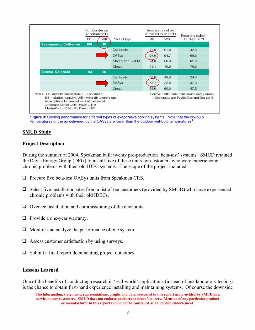
media and indirect heat exchanger enables OASys to cool air below the ambient wet bulb temperatures (refer to Figure 9 on the next page).
The information, statements, representations, graphs andservice to our customers. SMUD does not endorse produ
or manufacturer in this report should no
7
Figure 7: A poorly installed indirect-direct evaporative cooling system. The ductwork is far too restrictive to deliver the airflow needed to meet the cooling requirements of this classroom.6
Figure 8: Air flow diagram for the Speakman CRS OASys.7
data presented in this report are provided by SMUD as a cts or manufacturers. Mention of any particular product t be construed as an implied endorsement.
8
SMUD Study Project Description During the summer of 2004, Speakman built twenty pre-production ‘beta-test’ systems. SMUD retained the Davis Energy Group (DEG) to install five of these units for customers who were experiencing chronic problems with their old IDEC systems. The scope of the project included: Procure five beta-test OASys units from Speakman CRS.
Select five installation sites from a list of ten customers (provided by SMUD) who have experienced
chronic problems with their old IDECs. Oversee installation and commissioning of the new units.
Provide a one-year warranty.
Monitor and analyze the performance of one system.
Assess customer satisfaction by using surveys.
Submit a final report documenting project outcomes.
Lessons Learned One of the benefits of conducting research in ‘real-world’ applications (instead of just laboratory testing) is the chance to obtain first-hand experience installing and maintaining systems. Of course the downside
The information, statements, representations, graphs and data presented in this report are provided by SMUD as a service to our customers. SMUD does not endorse products or manufacturers. Mention of any particular product
or manufacturer in this report should not be construed as an implied endorsement.
Figure 9: Cooling performance for different types of evaporative cooling systems. Note that the dry-bulb temperatures of the air delivered by the OASys are lower than the outdoor wet-bulb temperatures1

9
The information, statements, representations, graphs and data presented in this report are provided by SMUD as a service to our customers. SMUD does not endorse products or manufacturers. Mention of any particular product
or manufacturer in this report should not be construed as an implied endorsement.
of this approach is that not all projects go smoothly. However, the lessons learned from these types of projects are invaluable in helping manufacturers identify and correct issues before mass production occurs. Listed below are some excerpts (in italics) from the Davis Energy Group report8. The complete report is available from SMUD upon request. The Davis Energy Group selected the five sites for OASys installation based on diversity of
installation type, access, installation ease, and proximity to DEG offices. Installation of the OASys systems involved removing the old IDECs, modifying the ductwork and support hardware. Shortly after the installs were completed, one of the customers sold her home. DEG and SMUD made repeated efforts to contact the new residents but were unsuccessful. Therefore this system was dropped from the project.
After the systems were installed, Speakman CRS determined that the water distribution header was
prone to clogging within a few months of use, depending on water quality. DEG worked with Speakman to develop a new water distribution system that required a less powerful pump, a modified direct stage and a new distribution header.
The new pump required changes to the control board program to prevent ‘air locking’ in the impeller
housing. Without the program modification, the media was not saturated with enough water to provide acceptable cooling.
The solutions were implemented in mid-Summer 2005 at all four active locations. Several building
occupants complained of poor cooling performance prior to the retrofit, suggesting that the header had already begun to clog. To our knowledge all four occupants they were satisfied with the system performance following the modifications.
One of the systems presented a number of service challenges that prevented it from operating
throughout much of the 2005 cooling season. In total, five issues were documented, as explained in detail below. Two of the problems were site-specific.
1. Problem: Thermostat wire from the original IDEC installation was deteriorated and faulty.
Solution: Thermostat wire was replaced.
2. Problem: Drain line from the original installation was prone to clogging. Solution: Drain line was replaced in September 2005.
3. Problem: Air locking in the pump. Solution: Changed the circuit board programming by installing a new computer chip.
4. Problem: Error made during installation of the computer chip.
Solution: Replaced the circuit board. 5. Problem: Error with the water level sensor.
Solution: Cleared debris from the sump and installed a screened hood to prevent further accumulation of debris.
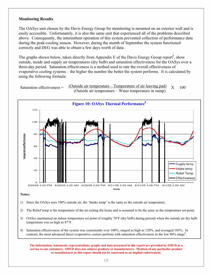
Monitoring Results The OASys unit chosen by the Davis Energy Group for monitoring is mounted on an exterior wall and is easily accessible. Unfortunately, it is also the same unit that experienced all of the problems described above. Consequently, the intermittent operation of this system prevented collection of performance data during the peak-cooling season. However, during the month of September the system functioned correctly and DEG was able to obtain a few days worth of data. The graphs shown below, taken directly from Appendix E of the Davis Energy Group report8, show outside, inside and supply air temperatures (dry bulb) and saturation effectiveness for the OASys over a three-day period. Saturation effectiveness is a method used to rate the overall effectiveness of evaporative cooling systems – the higher the number the better the system performs. It is calculated by using the following formula:
The information, statements, rservice to our customers. SMU
or manufactur
Saturation effectiveness = (Outside air temperature – Temperature of air leaving pad) X 100 (Outside air temperature – Water temperature in sump)
Notes: 1) Since the OASys uses 100% ou
2) The Relief temp is the temperat
3) OASys maintained an indoor tetemperature was as high as 87°F
4) Saturation effectiveness of the scontrast, the most advanced dire
Figure 10: OASys Thermal Performance8
tside air, the ‘Intake temp’ is the same as the outside air temperature.
ure of the air exiting the home and is assumed to be the same as the temperature set-point.
mperature set point of roughly 70°F (dry bulb) during periods when the outside air dry bulb .
ystem was consistently over 100%, ranged as high as 120%, and averaged 105%. In ct evaporative coolers perform with saturation effectiveness in the low 80% range8.
10
epresentations, graphs and data presented in this report are provided D does not endorse products or manufacturers. Mention of any parti
er in this report should not be construed as an implied endorsement.
by SMUD as a cular product
11
The information, statements, representations, graphs and data presented in this report are provided by SMUD as a service to our customers. SMUD does not endorse products or manufacturers. Mention of any particular product
or manufacturer in this report should not be construed as an implied endorsement.
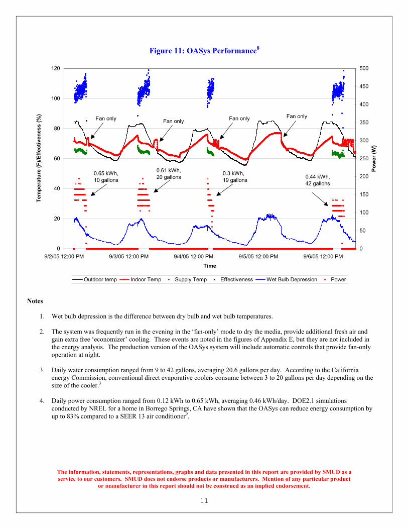
Figure 11: OASys Performance8
0
20
40
60
80
100
120
9/2/05 12:00 PM 9/3/05 12:00 PM 9/4/05 12:00 PM 9/5/05 12:00 PM 9/6/05 12:00 PM
Time
Tem
pera
ture
(F)/E
ffect
iven
ess
(%)
0
50
100
150
200
250
300
350
400
450
500
Pow
er (W
)
Outdoor temp Indoor Temp Supply Temp Effectiveness Wet Bulb Depression Power
Fan onlyFan onlyFan onlyFan only
0.65 kWh, 10 gallons 0.44 kWh,
42 gallons
0.3 kWh, 19 gallons
0.61 kWh, 20 gallons
Notes
1. Wet bulb depression is the difference between dry bulb and wet bulb temperatures. 2. The system was frequently run in the evening in the ‘fan-only’ mode to dry the media, provide additional fresh air and
gain extra free ‘economizer’ cooling. These events are noted in the figures of Appendix E, but they are not included in the energy analysis. The production version of the OASys system will include automatic controls that provide fan-only operation at night.
3. Daily water consumption ranged from 9 to 42 gallons, averaging 20.6 gallons per day. According to the California
energy Commission, conventional direct evaporative coolers consume between 3 to 20 gallons per day depending on the size of the cooler.3
4. Daily power consumption ranged from 0.12 kWh to 0.65 kWh, averaging 0.46 kWh/day. DOE2.1 simulations conducted by NREL for a home in Borrego Springs, CA have shown that the OASys can reduce energy consumption by up to 83% compared to a SEER 13 air conditioner9.

12
The installed cost for the OASys units in the SMUD study averaged $9,400 per unit. This is significantly higher than direct evaporative coolers but is comparable with local air conditioning retrofit projects. However, the real benefit from the OASys isn’t lower first cost – it is the potential for significant energy savings. According to DOE2.1 simulations conducted by the National Renewable Energy Laboratory for a house in Borrego Springs, CA, the OASys can reduce energy consumption by up to 83% compared to a conventional SEER 13 air conditioner9. Customer Survey Results Since one of the project objectives was to determine customer satisfaction, qualitative surveys were prepared and sent to the four active test sites. Results: Two of the four occupants indicated that overall they were “very satisfied” with their OASys units
and stated that energy savings, cooling comfort, and performance as expected were the specific factors contributing to their satisfaction8. The remaining two responses characterized their overall satisfaction level as “somewhat dissatisfied.”
Although both respondents indicated that OASys cooling was “more comfortable” than with their previously existing IDEC systems, one complained of insufficient cooling under extreme conditions while the other cited reliability and repair issues which rendered the OASys inoperable for much of the cooling season. The respondent citing insufficient cooling capacity was a chiropractic office that likely has higher cooling loads than the residential applications8.
Building America Study During 2004 – 2005, the U.S. Department of Energy’s Building America (BA) Program sponsored an evaluation of an OASys prototype in Magna, Utah. This study was conducted by the Consortium for Advancements in Residential Building, a Building America team led by Steven Winter Associates, and included two months of monitoring of an OASys installed in a two-story home. The two graphs shown below, reprinted with permission, provide some interesting insights: 1. OASys was able to maintain
comfortable indoor temperatures (average 70°F) even when the outdoor conditions exceeded ASHRAE 1% design conditions outdoor dry-bulb temperature for Salt Lake City, Utah.9 (Figure 12)
2. Occupants used the OASys in the ventilation-only mode during the nighttime hours to pre-cool the home9 in a similar manner to a whole house fan. (Figure 12)
The information, statements, representations, graphs and data presented in this report are provided by SMUD as a service to our customers. SMUD does not endorse products or manufacturers. Mention of any particular product
or manufacturer in this report should not be construed as an implied endorsement.
50
55
60
65
70
75
80
85
90
95
100
12:00 AM 6:00 AM 12:00 PM 6:00 PM 12:00 AM
Tem
pera
ture
, F
BR 21st FlBasementOutdoor Ambient
Figure 12: Indoor and outdoor temperatures for OASys in Magna Utah9
13
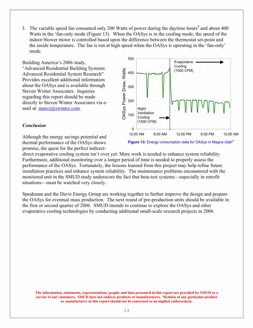
3. The variable speed fan consumed only 200 Watts of power during the daytime hours9 and about 400
Watts in the ‘fan-only mode (Figure 13). When the OASys is in the cooling mode, the speed of the indoor blower motor is controlled based upon the difference between the thermostat set-point and the inside temperature. The fan is run at high speed when the OASys is operating in the ‘fan-only’ mode.
Building America’s 2006 study, “Advanced Residential Building Systems: Advanced Residential System Research” Provides excellent additional information about the OASys and is available through Steven Winter Associates. Inquiries regarding this report should be made directly to Steven Winter Associates via e-mail at: [email protected]. Conclusion Although the energy savings potential and thermal performance of the OASys shows promise, the quest for the perfect indirect- direct evaporative cooling system isn’t over yet: More work is needed to enhance system reliability. Furthermore, additional monitoring over a longer period of time is needed to properly assess the performance of the OASys. Fortunately, the lessons learned from this project may help refine future installation practices and enhance system reliability. The maintenance problems encountered with the monitored unit in the SMUD study underscore the fact that beta-test systems—especially in retrofit situations—must be watched very closely. Speakman and the Davis Energy Group are working together to further improve the design and prepare the OASys for eventual mass production. The next round of pre-production units should be available in the first or second quarter of 2006. SMUD intends to continue to explore the OASys and other evaporative cooling technologies by conducting additional small-scale research projects in 2006.
The information, statements, representations, graphs and data presented in this report are provided by SMUD as a service to our customers. SMUD does not endorse products or manufacturers. Mention of any particular product
or manufacturer in this report should not be construed as an implied endorsement.
0
100
200
300
400
500
12:00 AM 6:00 AM 12:00 PM 6:00 PM 12:00 AM
OA
Sys
Pow
er D
raw
, Wat
ts
Night Ventilation Cooling(1500 CFM)
Evaporative Cooling(1000 CFM)
Figure 13: Energy consumption data for OASys in Magna Utah9
14
The information, statements, representations, graphs and data presented in this report are provided by SMUD as a service to our customers. SMUD does not endorse products or manufacturers. Mention of any particular product
or manufacturer in this report should not be construed as an implied endorsement.
References We gratefully acknowledge the contributions made from the following sources: 1. “Death of the Swamp Thing: Evaporative Cooling Delivers Dry Air,” by Peter Crisione, ET Currents
Number 41, April 2005. Platts Research & Consulting, 3333 Walnut Street, Boulder, CO 80301-2515. USA, tel (303)-444-7788, www.esource.platts.com
2. USA Today Research by Chad Palmer, available http://www.usatoday.com/weather/wsling.htm
3. “Evaporative Cooling,” California Energy Commission, available at
www.consumerenergycenter.org/homeandwork/homes/inside/heatandcool/evaporative_coolers.html# 4. “Installing and Maintaining Evaporative Coolers,” by Roy Otterbein, Home Energy Magazine
Online May/June 1996. Available at http://homeenergy.org/archive/hem.dis.anl.gov/eehem/96/960511.html
5. “Energy-Efficient Ducted Evaporative Coolers,” Pacific Gas and Electric Company, available
http://www.pge.com/docs/pdfs/res/rebates/EEDECTechSheetv5.pdf 6. “Operation IDEC Rescue,” by Dave Bisbee, Sacramento Municipal Utility District, 6301 S Street,
Sacramento, CA 95817-1899, tel (916) 732-6409, available at www.smud.org/education/cat 7. “New Evaporative Cooling Systems: An Emerging Solution for Homes in Hot Dry Climates with
Modest Cooling Loads,” by Larry Kinney, Southwest Energy Efficiency Project, 2260 Baseline Road, Suite 212, Boulder, CO 80302 tel (303) 786-8054.
8. “SMUD-IDEC Project, OASys Retrofit Final Report” Davis Energy Group, 123 C Street, Davis, CA
95616 tel (530) 753-1100, http://www.davisenergy.com/ 9. DOE Building America Task Order No. KAAX-3-33411-08. "Advanced Residential Building
Systems: Advanced Residential System Research” Consortium for Advancements in Residential Building