Embed Size (px)
Citation preview

Custom Coated Flowline Products
Page 1
INDEX
1. Custom-Made Flowline Products with Internal Coating ………………… Page 2
2. Examples of Custom Fabricated Products by CCC Machinery ………..... Page 3
3. Reasons to Coat Pipe Internally ………………………..……………………… Page 5
4. Cost Comparison ………........................………………..……………………… Page 5
5. Examples of Coated vs. Uncoated Internal Surfaces ….…………….…… Page 6
6. Examples of Coated Flowline Products ..……..……………………………… Page 7
7. Calculation of Hydraulic Efficiency ……….…………………………………… Page 8
8. The Effects of Internal Coating in Monetary Terms …….………………… Page 9
9. Different Coatings for Different Applications ………….…………………… Page 10
10. Summary …………………………………………………..………………………… Page 12
11. End User References ..…………………………………..………………………… Page 14
12. Contact ……………………………………………………..………………………… Page 15

Page 2
1. CUSTOM-MADE FLOWLINE PRODUCTS WITH INTERNAL COATING
CCC Machinery fabricates and internally coats pipes, fittings and spools according to customers’ designs and specifications without any limitations to size, shape or design and according to the
applicable international oil industry standards.
Scope of Products
line pipe
drill pipe
OCTG
fittings
spools
manifolds
flanged connections
sleeves for welded connections
These custom-made flowline products can be internally coated with a choice of Tuboscope Vetco’s liquid and powder applied plastic coating products, which are highly resistant to chemical and
mechanical corrosion, thereby providing an unsurpassed longevity to drilling and flowline components.
Our flowline products also offer an economical and flexible method for field construction, tie-in’s,
terminations, modifications, and repair of internally coated lines, as they are designed for connection by welding (in combination with Thru-Kote TM UB Sleeves) or with flanges.
A great number of upstream and downstream end-users in the oil, gas and water producing industries
worldwide have come to appreciate the the cost-saving and production-increasing properties of our
internally coated products.

Page 3
2. EXAMPLES OF CUSTOM FABRICATED PRODUCTS BY CCC MACHINERY
Manifold design by Saudi Aramco / KOC Joint Operations (Kuwait) for fabrication and internal coating by CCC Machinery
U-sections after welding Manifold header after welding
Manifold header after sandblasting and prior to coating Coated internal surface of pipe section

Page 4
Manifold components being packed for shipment to Kuwait
Manifold after assembly at customer’s site in Kuwait
We supply the following certificates together with all our fabricated products:
Mills’ Test Certificates for bare pipe, fittings, flanges etc. issued by manufacturers
Welding Procedure Specification (WPS)
Procedure Qualification Record (PQR)
Welder’s Performance Qualifications (WPQ)
Radiographic Examination Reports
Visual Weld Inspection Reports
Design drawings
Coating Inspection Certificates issued by Vetco Coating GmbH
Adhesion Test Report issued by Vetco Coating GmbH
Inspection Certificates for coating raw material issued by Akzo Nobel
Third party Inspection Certificate issued by customer’s prescribed inspection company
X-ray images are kept on file by us for a period of minimum 5 years from date of test certificate
and are made available to the customer upon request

Page 5
3. REASONS TO COAT PIPE INTERNALLY
protect against CORROSION
increase PRODUCTION RATES
improve HYDRAULIC EFFICIENCY by
flow improvement
control DEPOSITION of
paraffin, asphaltene & scale
minimize TUBING WEAR by
erosion & abrasion mechanical damage
improve FLUID PURITY
reduce COSTS through
extended tubular life
less maintenance less workovers
less fishing
lower production costs lower purchasing investment compared to higher grade steel alloys (see comparison below)
4. COST COMPARISON
Steel Alloy
Cost Factor
Carbon Steel bare Carbon Steel with Internal Coating
Stainless Steel 316L Stainless Steel 904L
Inconel 625
Incoloy 825
100% (base cost) 150 - 200%
600% 900%
1800%
2200%

Page 6
5. EXAMPLES OF COATED VS. UNCOATED INTERNAL SURFACES
BaSO4 Scale Non adhering BaSO4 Scale in an internal coated pipe, easy to remove/clean and easy to decontaminate.
Calcium Carbonate Scale Scale deposits in uncoated pipe.
No scale deposits found in a coated pipe.
Salt Incrustation Salt blocking after 5 hours in a non internally coated pipe.
No salt incrustation after 336 hours in internally coated pipe.
The difference between coated and uncoated pipe.
Page 7
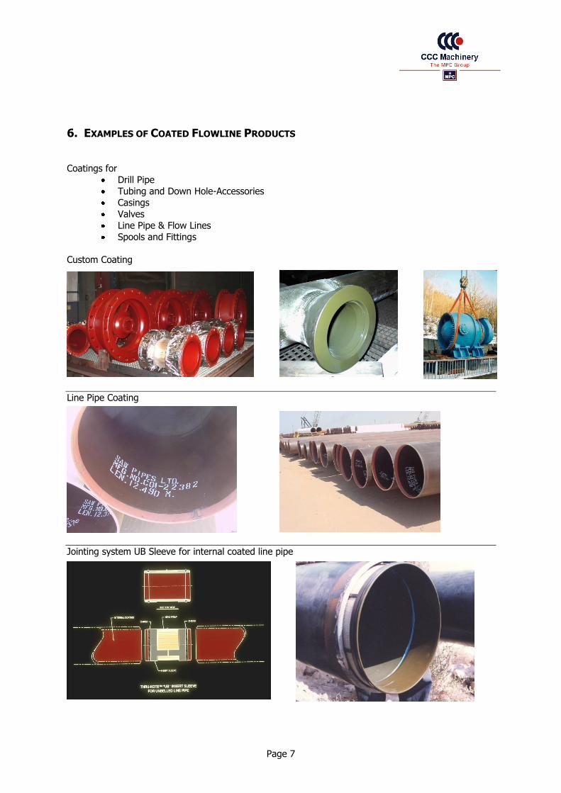
6. EXAMPLES OF COATED FLOWLINE PRODUCTS
Coatings for
Drill Pipe
Tubing and Down Hole-Accessories
Casings
Valves
Line Pipe & Flow Lines
Spools and Fittings
Custom Coating
Line Pipe Coating
Jointing system UB Sleeve for internal coated line pipe
Page 8
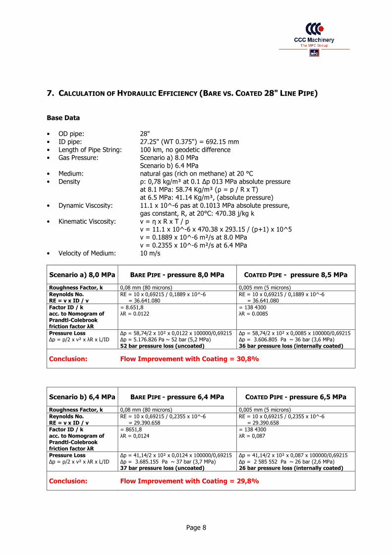
7. CALCULATION OF HYDRAULIC EFFICIENCY (BARE VS. COATED 28" LINE PIPE)
Base Data
• OD pipe: 28"
• ID pipe: 27.25" (WT 0.375") = 692.15 mm
• Length of Pipe String: 100 km, no geodetic difference • Gas Pressure: Scenario a) 8.0 MPa
Scenario b) 6.4 MPa • Medium: natural gas (rich on methane) at 20 °C
• Density ρ: 0,78 kg/m³ at 0.1 Δp 013 MPa absolute pressure at 8.1 MPa: 58.74 Kg/m³ (ρ = p / R x T)
at 6.5 MPa: 41.14 Kg/m³, (absolute pressure)
• Dynamic Viscosity: 11.1 x 10^-6 pas at 0.1013 MPa absolute pressure, gas constant, R, at 20°C: 470.38 j/kg k
• Kinematic Viscosity: ν = η x R x T / p ν = 11.1 x 10^-6 x 470.38 x 293.15 / (p+1) x 10^5
ν = 0.1889 x 10^-6 m²/s at 8.0 MPa
ν = 0.2355 x 10^-6 m²/s at 6.4 MPa • Velocity of Medium: 10 m/s
Scenario a) 8,0 MPa BARE PIPE - pressure 8,0 MPa COATED PIPE - pressure 8,5 MPa
Roughness Factor, k 0,08 mm (80 microns) 0,005 mm (5 microns)
Reynolds No. RE = v x ID / ν
RE = 10 x 0,69215 / 0,1889 x 10^-6 = 36.641.080
RE = 10 x 0,69215 / 0,1889 x 10^-6 = 36.641.080
Factor ID / k = 8.651,8 = 138 4300 acc. to Nomogram of Prandtl-Colebrook friction factor λR
λR = 0.0122 λR = 0.0085
Pressure Loss Δp = ρ/2 x v² x λR x L/ID
Δp = 58,74/2 x 10² x 0,0122 x 100000/0,69215 Δp = 5.176.826 Pa ~ 52 bar (5,2 MPa)
Δp = 58,74/2 x 10² x 0,0085 x 100000/0,69215 Δp = 3.606.805 Pa ~ 36 bar (3,6 MPa)
52 bar pressure loss (uncoated) 36 bar pressure loss (internally coated)
Conclusion: Flow Improvement with Coating = 30,8%
Scenario b) 6,4 MPa BARE PIPE - pressure 6,4 MPa COATED PIPE - pressure 6,5 MPa
Roughness Factor, k 0,08 mm (80 microns) 0,005 mm (5 microns)
Reynolds No. RE = v x ID / ν
RE = 10 x 0,69215 / 0,2355 x 10^-6 = 29.390.658
RE = 10 x 0,69215 / 0,2355 x 10^-6 = 29.390.658
Factor ID / k = 8651,8 = 138 4300 acc. to Nomogram of Prandtl-Colebrook friction factor λR
λR = 0,0124 λR = 0,087
Pressure Loss Δp = ρ/2 x v² x λR x L/ID
Δp = 41,14/2 x 10² x 0,0124 x 100000/0,69215 Δp = 3.685.155 Pa ~ 37 bar (3,7 MPa)
Δp = 41,14/2 x 10² x 0,087 x 100000/0,69215 Δp = 2 585 552 Pa ~ 26 bar (2,6 MPa)
37 bar pressure loss (uncoated) 26 bar pressure loss (internally coated)
Conclusion: Flow Improvement with Coating = 29,8%

Page 9
8. THE EFFECTS OF INTERNAL COATING IN MONETARY TERMS
Effects of Internally Coated Tubing
Lower Flowing Pressures
Lower Abandonment Pressure
Lower Injection Pressure
Accelerated Revenues from Increased Production
Protection from Corrosion
Protection from mechanical damage
Protection from stimulation
Gas Production Field Results
Coating: TK-236
Reservoir Pressure: 2,500psi
Wellhead Pressure: 1,500 psi
Tubing Size: 5 ½” 13CR
Coating Roughness: < 5 microns (after 10 years)
Gas Capacity Coated Pipe: 1.88 million m3 per day
Gas Capacity Bare Pipe: 1.64 million m3 per day
The operator realizes a 15% increase in production capacity with internal coating.
Gas Production Field Results Cost of Coating vs. Increased Revenues
0
10
20
30
40
50
60
70
80
Ga
s R
ate
MM
CF
D
A B C D E
Wells
Bare Coated
$0
$200.000
$400.000
$600.000
$800.000
$1.000.00
0
$1.200.00
0
$1.400.00
0
A B C D E

Page 10
9. DIFFERENT COATINGS FOR DIFFERENT APPLICATIONS
Tuboscope Vetco Coating Product Line
Coating Type Temperature
°F °C Principal Service
TK-2 Phenolic (liquid)
400° 204° Oil Production, Water injection, Co2 and organic acid resistance.
TK-7 Modified Phenolic (liquid)
400° 204° Sour gas and oil to 300 °F, oil, gas and Co2 to 400 °F
TK-21 Epoxy Polyamide (liquid)
150° 66° Water, crude oil, mild caustic, mild hydrocarbons.
TK-15 Modified Novolac (powder)
300° 149° Oil, natural gas, fresh and salt water,sweet corrosion(Co2), mild H2S, and alkaline service.
TK-33 Urethane (liquid)
225° 107° Paraffin and scale prevention.
TK-34 Modified Ep-Phenolic (liquid/powder)
* * Drill Pipe
TK-69 Epoxy mod. Phenolic (liquid/powder)
250° 121° Oil, fresh and salt water, Co2 acids, caustic completion fluids, and gases in miscible injection systems.
TK-70 Epoxy (powder) 175° 79° Oil, fresh and salt water handling service. Excellent in stimulation acids.
TK-99 Polyamide (nylon powder)
225° 107° High flexible coating for line pipe and tubing in oil, fresh and saltwater service.
TK-216 Modified Ep-Phenolic (powder)
200° 95° Surface and subsurface, water handling systems, crude oil, mild caustic and mineral acids, and disposal wells.
TK-236 Modified Novolac (powder)
400° 200° High pressure, sweet and sour oil/gas wells, and tertiary oil recovery systems.
Coating Chemistry
Chemistry Characteristics
Epoxy Temperature limit 225ºF (95°C), the amount of flexibility and temperature
resistance are inversely related. Inherently have a fair amount of chemical resistance.
Phenolic Temperature limit 400ºF (204°C), high abrasion and temperature
resistance along with good chemical resistance. Can be brittle.
Epoxy Phenolic Temperature limit 250ºF, produce a middle of the road coating with good flexibility, temperature resistance, and chemical resistance.
Novolac
(Phenol /Epoxy/Cresol)
Temperature limit 400ºF (204°C), excellent chemical resistance in acid and
alkaline environments, temperature resistance close to a phenolic, and flexibility similar to a phenolic.
Nylon Temperature limit 225ºF (95°C), a thermoplastic, excellent flexibility and
abrasion resistance with very good chemical resistance.

Page 11
Polymeric Coating Systems for Down Hole Applications
Liquid applied, baked on
Powder applied, baked on
Factors determining Coating Selection
Environments
Pressure
Temperature
ph level
Velocities
Well/Line design
Well treatments
Types of Downhole Corrosion
Chemical corrosion: CO2, H2S, Cl, Oxygen, Water
Mechanical corrosion: SCC, Erosion, Fatigue
Electro-chemical, Galvanic corrosion
Coating Performance Influenced by
Pipe quality
Pipe handling systems
Pipe running procedures
Connection systems
Well intervention and wire line work
Design of wire line equipment
Primary Factors Influencing Flow Inside Pipe
Velocity of medium
Viscosity of medium
Geometry of pipe
Roughness of pipe surface
Primary Considerations When Selecting Internal Coatings
Compatibility with service environment
Applicator procedures & quality program
Pipe handling practices
Production practices
Mechanical properties of coating
Are formulator, coating manufacturer & applicator unified?

Page 12
10. SUMMARY IMPROVEMENT OF TUBING EFFICIENCY BY ELIMINATION OF INTERNAL CORROSION AND/OR SCALING To a great extent, the profitability of production and injection wells depends on the lifetime of the used tubing string. The replacement of a tubing string always creates additional costs for buying new tubes, for workover services, the inspection and transportation of pipe. Also, lost production has to be considered as a major cost item. Taking above facts into consideration it is easy to conclude the following: The extension of the operational time between workovers means to be the key function regarding the profitability of the production and/or injection well. Among several possibilities such as the utilization of corrosion inhibitors or the utilization of high alloy steel, internal coating of tubular has proven to be successful in practice:
Coating + inhibitors Coating + high alloy steel
Almost all types of corrosion which appear in connection with oil production and water injection today, can be fought by application of Tuboscope's internal powder coating systems. Types of Corrosion:
CO2-Corrosion H2S-Corrosion (up to 30% H2S content) Oxygen Corrosion Bacterial Corrosion Saltwater Corrosion
Following the latest materials and application techniques, new internal coatings had been developed which can be utilized at temperatures up to 200°C with a totally holiday free surface. Even gas pressures > 500 bar inside the production tubular with rapid decompressions will not create any problem to Tuboscope Vetco's internal coating systems today. Most of the tubing connections in use - which admittedly represent critical areas inside the string with regard to the homogeneity of the internal coating - can reliably be coated according to Tuboscope's Coating's Procedures and Tuboscope's SOP. With some caution during the trip-in (using Stabbing Guides) these critical areas remain holiday-free even after installation. OTHER ADVANTAGES OF INTERNAL COATING SYSTEMS Among its major task to prevent corrosion, the internal coating provides other advantages, i.e. prevention of scale built-up and improvement of volumetric performance. Paraffin, carbonate deposits and salt scale as well as deposits of radioactivity containing materials can be delayed up to three to four times if using internally coated pipe. This can be achieved because of the very smooth coating surface of < 5 µm. This very low surface roughness also leads to a tremendous improvement of the hydraulic conditions (volumetric efficiency), which works out very positively with higher production respectively injection rates. Production increase of > 20 % is achieved. From time to time most production wells need to be stimulated with acid. Also for this type of work the coating will protect the tubing string effectively. The best results for the extension of the operational time of a production well will be achieved if in addition to the coated tubing all other components used for production and injection are coated, i.e. packers, pup joints, subs, tubing hanger etc. Other downhole equipment in contact with corrosive fluids should be coated as well. Above ground the gathering lines, valves etc. should be coated to prevent corrosion.

Page 13
Example: CORROSION PROTECTION AND IMPROVED HYDRAULIC EFFICIENCY OF DRILL PIPE Internally coated drill pipe are increasingly used since more than three decades. As a passive corrosion protection the coating is acting as a barrier to avoid direct contact between the steel pipe and the corrosive medium (fluid/gases etc.), thus avoiding corrosion. Drilling: Today's used drilling fluids can be classified as 'non corrosive' up to 'extremely corrosive'. Since within the lifetime of a drill string the utilization will be for all different environments, possible corrosion caused by aggressive muds have to be considered. Testing and Stimulation: Downhole tests as well as stimulation services very often initiate extremely corrosive environments. Especially CO2 and H2S are influencing the corrosion rate. Acids used for stimulation purposes in connection with high bottom hole temperatures lead to high corrosion rates although stimulation periods are relatively short. Storage of Drill Pipe: Practically all drill pipes remain in storage for shorter resp. longer periods. This can happen directly at the rig site or at the pipe yard. During this time the uncoated internal drill pipe surface very often is subject to the so-called rack corrosion. Left drilling fluid, oxygen and condensate are generating a corrosive environment especially attacking the internal surface of drill pipe. ADVANTAGES OF INTERNAL COATING Corrosion Protection Primarily corrosion within drill pipe is starting as a type of pitting corrosion. Due to cyclical stresses as encountered in drilling any given section of the drill pipe in operation is permanently under tensile stress (weight of the string), internal respectively external pressure (mud system) and under alternate compressive and tensile stresses due to the deviation of the hole being drilled, the corrosion pittings develop into transversal cracks (notch effect). This phenomenon, which is called “stress corrosion cracking”, is developing perpendicular to the main stress direction. Although the transversal cracks inside a drill pipe generally develop over the entire length, a certain preference for the end areas is found in practice due to the change in cross sectional areas. Washouts and/or ruptures predominantly up to one meter behind the upsets are known in the drilling industry. With today's application of internally coated drill pipe the internal corrosion can be controlled. Without internal corrosion no notch effect can occur. Stress corrosion cracking with all consequences such as washouts and/or pipe ruptures does not represent a problem anymore if drilling companies uses internally coated drill pipe. Even wireline cuts which may develop after some time in service - especially within the tool joint and upset areas - do not limit the positive performance of internal coatings. Hydraulic Efficiency One major advantage of internally coated drill pipe is found in the improved hydraulic efficiency. Effected by the very smooth (glossy) internal surface of the drill pipe, the pressure drop can be reduced considerably inside the drill string. This results in either energy savings during drilling or (more probably) in a higher drilling speed since a higher pressure is available at the bit.
Energy savings of > 9 % and better Circulation rates of > 14 % can be achieved
An additional positive effect is the reduction in scale build-up achieved by the glossy and smooth internal surface. Moreover, the cleaning of internally coated pipe is much easier and more efficient. Summary Today more than 90% of the western world drill pipe are internally plastic coated providing a less risk drilling operation, an increased life time and energy savings while drilling. It is standard to the drilling industry to day to utilize coated drill pipe even during harsh drilling environments.
Corrosion mitigation costs are reduced by extending life of down hole tubular goods.
Lower descaling costs and longer production schedules.
Increased production in high volume wells or smaller pipe sizes can be utilized.
Greater mud velocities in drilling or reduced pump maintenance by reduction of pressure.
Eliminates contamination of a reservoir with corrosion products during water flooding.

Page 14
11. END USER REFERENCES The following customers are using coated industrial items for the oilfield, drinking water, waste water and sewage, as well as for the mining industry. Coated items are: pipes, pipe spools, fittings, flanges, valves (ball valves, gate valves, check valves) etc. coated with fusion bonded powder coatings or thermal cured liquid phenolics.
Customer Country Customer Country
ADNOC (Abu Dhabi National Oil Co.) United Arab Emirates Mobil Germany
Agip Congo Mokveld Valves Netherlands
Aker Subsea Norway NAM B.V. (Nederl. Aardolie Maatsch.) Netherlands
Al-Furat Shell Syria NIGC Iran
AMOCO Scotland NOC Libya
AMOCO Gabon Normec Oilfield Products Germany
ARAMCO Saudi Arabia OMV AG Austria
Baker Hughes Inteq Germany Orbit Valve Italy
Baker Oil Tools Germany Petro Valve Italy
BEB Erdgas und Erdöl GmbH Germany Preussag AG Germany
Bjorge Offshore Norway Raimondi Italy
BP (British Petroleum) North Sea Ring-O-Valve Italy
BP Expro (Britoil) United Kingdom RMA Germany
BRDR Christensens Haner A/S Denmark Ruhrgas AG Germany
CONOCO Scotland RWE Germany
CONOCO North Sea SDT Valve France
Conoco (UK) Ltd. United Kingdom Shell Expro North Sea
DEA Mineralöl AG (formerly Texaco) Germany Shell Expro Scotland
DEE (Deilmann Erdöl Erdga GmbH) Germany Solber & Andersen Norway
Dong Denmark Sonatrach Algeria
EA Mineralöl AG Germany Sonatrach Algeria
EDECO Netherlands Statoil Norway
EE Caledonia (formerly Occidental Petrol.) Scotland Sun Oil Scotland
Elf Acquitaine France TOMEK (Total Oil Marine Aberdeen) North Sea
Frames Process Systems Netherlands Tormene SpA Italy
Gaz de France France UNOCAL Netherlands
Gazprom Russia VAG Germany
Haugesund Mek. Verkst Norway Vitas Srl Italy
KOC (Kuwait Oil Company) Kuwait Waha Libya
Kvaerner Subsea Contr. Norway Wintershall AG Germany
Marathon Oil United Kingdom Zueitina Libya
Please contact us if any detailed field reports from the existing end users are required.

Page 15
12. CONTACT
Company Residence Postal Address
CCC Machinery GmbH Tubular Division Palmaille 67 D-22767 Hamburg Germany
CCC Machinery GmbH Tubular Division PO Box 50 10 40 D-22710 Hamburg Germany
Name Title / Function Direct Tel. E-mail
Detlev Wahl Managing Director +49 40 38022 7401 [email protected]
Sabine Kürtz Assistant +49 40 38022 7402 [email protected]
Ekkehard M. Ebert Director Tubular Div. +49 40 38022 7454 [email protected]
Björn Laubscher Area Manager Sales +49 40 38022 7453 [email protected]
Mohamed Drahmoune Area Manager Sales +49 40 38022 7452 [email protected]
Jorge Alejandro Prado Area Manager Sales +49 40 38022 7429 [email protected]
Niklas Hemptenmacher Area Manager Sales +49 40 38022 7456 [email protected]
Christian Wille Order Processing +49 40 38022 7476 [email protected]
Fax Number Tubular Division +49 40 38022 7444
VAT Registration Number DE 812668979
Company Registration Number HRB 77678