Embed Size (px)
Citation preview
www.instituteofplay.org
Short Circuit is a fun and creative approach to electronics and physical computing for young people. The modules included in this guide have all the information you need to get started!
Version 1.0
CURRICULUM GUIDE

pg. 2
www.instituteofplay.org
SHORT CIRCUIT CURRICULUM
How do I use this Short Circuit Curriculum guide?
SHORT CIRCUIT:THEN AND NOW
The following seven modules each contain a complete Short Circuit experience. Every module starts out with an overview, followed by more detailed information about the learning goals, key terminology, materials needed, and any tips or links to assist with its implementation. Tips for modding the modules to di�erentiate for varied student skill levels are there, as well. Following the lesson plans are individualized assessment tools.
These modules were created as a complete sequence, but following that sequence isn’t necessary. Each module stands on its own— making it possible to mix and match modules to fit your needs. It would be a great idea to check out the Short Circuit Professional Development curriculum if you are new to electronics or physical computing. This can also be found on the Institute of Play website. Each of the student modules is linked to at least one Professional Development curriculum module, so you know exactly where to go if you need to brush up on the basics.
Short Circuit started as an after school program at Quest to Learn in New York City in 2009. It has grown into an informal hands-on laboratory for participants to explore and discover innovative uses for physical and digital materials, like circuits, conductive inks, LEDs, the latest programming languages, paper, pipe cleaners, iPads, video, audio and websites.
The Short Circuit experience is one where young people tinker at the intersection of design, technology and art. The program is designed to support the development of creativity, innovation, systems thinking and DIY digital media skills by engaging participants in informal projects under the guidance of educators, artists and designers. The program also supports current science, technology, engineering and math objectives (STEM).
Students in Short Circuit explore a variety of materials, from building blocks to conductive fabric.

pg. 3
www.instituteofplay.org
SHORT CIRCUIT CURRICULUM
Felted puppets that light up when they touch one another
LED Puppet
A hacked greeting card is turned into a mutated musical boombox
Cereal Boombox
A unique one button video game controller created from an old computer mouse and a cardboard box
One-Button Hack
What is Short Circuit curriculum?The Short Circuit experience is one where young people tinker at the intersection of design, technology and art. This seven module sequence is intended to develop the participants’ technological skills while allowing them to express themselves creatively.
Low-cost and low-power flashlight made from scratch
LED Flashlight
A simple program and circuit to play back miniature melodies
Noise Machine(Arduino)
Push button light up quiz show style device
Quiz Show Controller
Worksheets to help track your students learning
Assessment Tools
Unique light-up papercraft decorations for any holiday
Papercraft Jack-O’-Lantern
$3

pg. 4
www.instituteofplay.org
SHORT CIRCUIT ASSESSMENT
BEFORE YOU BEGIN
ASSESSMENT
SYSTEMS THINKING SKILLS:
Short Circuit focuses on the creation of circuits, which are systems of electronic com-ponents. Short Circuit will strengthen students' under-standing of how a system func-tions in a number of ways.
relationships between components of a system and how they interact.
how some components of a system are essential to how it works, and how others are not.
LEARNING GOALS: What will be covered?
the qualities and behaviors of components of a system.
Students will be able to identify:
the components of a system.

pg. 5
www.instituteofplay.org
CONTEXT & BACKGROUND for all modules
SHORT CIRCUIT ASSESSMENT
ASSESSMENT
Essential Questions Activated:
What are the components of a system?
Are all components in a system the same? How do they differ?
Are all components of a system equally important in contributing to the system meeting its goal?
Key Skills for Systems Thinking:
Learning how to break a system down into parts, or components.
Being able to describe the qualities or rules that define a component.
Understanding what components really matter to the system. In other words, which ones are critical to making it work or meet its goal.
KEY SKILLS AND QUESTIONS: What will be covered?
CONTENT KNOWLEDGE AND SKILLS:
Technology:Standard 9 Students develop an understanding of engineering design.
Standard 10Students develop an understanding of the role of troubleshooting, research and development, invention and innovation, and experimentation in problem solving.
Standard 11 Students develop the abilities to apply the design process.
Engineering:Standard K Students develop the ability to use the techniques, skills and modern engineering tools necessary for engineering practices.
DESIGN THINKING:Representation Competency Students create multiple types of representations such as diagrams, graphs, tables, sketches, illustrations, or physical forms, enabling them to structure, record, and express ideas.Use of multiple representations is a critical design thinking strategy.
ADDITIONALLEARNING GOALS: What will be covered?

pg. 6
www.instituteofplay.org
SHORT CIRCUIT ASSESSMENT
ASSESSMENT
••••••••••••
List the major components to label
Draw your diagram below:
WORKSHEET 1
Now it’s time to create a diagram of your circuit. Use this space to show a rough sketch of the design, including all electrical components. Be sure to label all components that you draw in your diagram.
DIAGRAM OF YOUR CIRCUIT

pg. 7
www.instituteofplay.org
SHORT CIRCUIT ASSESSMENT
ASSESSMENTWORKSHEET 2- System Skills
1. Choose at least three of the major components of your design and explain their role in the circuit.•
•
•
3.Name one component you could remove from this circuit and the circuit would still function. If every component is needed for the circuit to work, explain what would happen if you removed one of the major components.
2.For the components you chose, explain their interaction: how do the components work together within the circuit?•
•
•
4.Can you think of a component to add to the circuit? How would that change the way it functions? Explain.

pg. 8
www.instituteofplay.org
SHORT CIRCUIT ASSESSMENT
ASSESSMENTWORKSHEET 3- Self-Reflection & Review
1. How did you decide on the final design for your project?
3.What did you learn about circuits or electronics in this activity?
2.What was the hardest part of this activity for you? Why?
4.If you could do this project again, what would you change? Why?

OVERVIEW: What’s on for today and why?
Big Idea of the Session:
To be able to create a custom one-button video game controller out of computer mice and cardboard.At a Glance:
Students will solder wire to the middle button of a mouse and remap it to a keyboard key to play a one-button game. Results:
Students will create a cool and unique controller out of cardboard, tape, and mice parts to play their favorite one-button games with.
SHORT CIRCUIT ACTIVITY 1
ONE-BUTTON HACK
pg. 9SHORT CIRCUIT ACTIVITY 1
www.instituteofplay.org
One 120-minute session (two hours)
beginner

pg. 10
www.instituteofplay.org
CONTEXT & BACKGROUND
SHORT CIRCUIT ACTIVITY 1
SolderA fusible metal alloy used to join together metal pieces.
Soldering ironA tool used for melting solder and applying it to metals that are to be joined.
Button (momentary push-button switch)A button when pressed that closes and completes a circuit, by allowing current to flow.
Electric circuitAn unbroken path along which an electric current exists or is intended to flow.
MultimeterAn instrument designed to measure electric current, voltage, and usually resistance, typically over several ranges of value.
KEY TERMS: Definitions you need to know first
ONE-BUTTON HACK
DELIVERABLE:
Students will be assessed with their final product, a one-button controller hooked up to a computer to control a video game of their choice. The controller housings are decorated to their liking. Above: a completed controller
Below: taking apart the computer mouse

BEFORE YOU BEGIN
pg. 11
www.instituteofplay.org
GETTING READY:Last minute tips
INSTRUCTIONAL RESOURCES: For more information
SHORT CIRCUIT ACTIVITY 1
Have a prototype of the circuit to show to the students with all components listed.See below.
Have a prototype of the final product on hand to show the students.
Set up the soldering irons ahead of time, spread apart, to allow students space to work without interfering with each other.
Set up Autohotkey on your computer.
Set up arts & crafts materials in one central location.
CHECK OUT SESSIONS 1 & 2of the Short Circuit Professional Development series
HOW TO MOD MICE:http://www.1728.org/mousemod.htm
HOW TO SOLDER:http://www.aaroncake.net/electronics/solder.htm
HOW TO DESOLDER (with photos): http://www.epemag.wimborne.co.uk/desolderpix.htm
ONE-BUTTON GAMES:http://www.kongregate.com/one-button-games
HOW TO USE AUTOHOTKEY:http://www.autohotkey.com/docs/misc/Remap.htm
MATERIALS: What you’ll needFOR EACH STUDENT YOU WILL NEED:
Cardboard
FOR THE GROUP YOU WILL NEED:
Solder
Soldering irons
Phillips screwdriver
Momentary push button (arcade button preferred)
Computer mice
Wire
Cardboard
Desoldering pumps or desolder (copper) braid
Scissors
Box-cutting knives
Glue guns
Paper tape
Duct tape
Electrical tape
Wire stripper
ONE-BUTTON HACK
Soldering lead wires onto the mouse buttons

LESSON PLAN: Step by step implementation
THE PLAN
pg. 12
www.instituteofplay.org
SHORT CIRCUIT ACTIVITY 1
STEP 5Soldering:
Cut two long wires and solder them to the back of the solder board where the middle mouse button leads are. Solder the other end of the leads to a push-button.
STEP 6Design:
Let the students build a cardboard housing for their buttons.STEP 7Putting it All Together:
Students will seal up their designs, taping or hot gluing their circuit inside their cardboard housing.STEP 8Play Test 2:
Plug in controllers and test arcade buttons.
STEP 3The Circuit:
When the circuit board is finally exposed, show the students where the middle mouse buttons are and the leads that they will be soldering to.STEP 4Autohotkey:
Install setup Autohotkey. Map the middle mouse button to the button that the game uses (i.e. “space bar,” “x,” “c,” etc.).
STEP 1Play Test:
Download and play a few one-button games off of Kongregate.Have the students choose their favorite games. Some will have a few di�erent selections.
STEP 2Destruction:
After putting away the laptops, students will take apart a mouse by either unscrewing it from the bottom or slamming it into the ground to access the circuit board.
ONE-BUTTON HACK
Any standard arcade button will work for this activity

pg. 13
www.instituteofplay.org
SHORT CIRCUIT ACTIVITY 1
ONE-BUTTON HACKTIPS & EVALUATION
REFLECTWorksheets: Have students complete all assessment evaluation worksheets for this activity.
WRAP UPCircle Up: After the worksheets are completed, come together for a conversation to share these thoughts. Go around the room and have each student share something that they wrote in their self-reflection.
DEBUGGINGCircuit not working?Use this checklist to help you get to the bottom of your problem.
ª If the buttons aren’t responding, make sure each wire is correctly soldered to the mouse. A loose soldering joint could cause irregular behavior.
ª If the buttons still aren’t responding, check the joints on the push-button. They can often come loose if not soldered properly. Once soldered properly, a touch of hot glue can keep the joint in place.
Momentary buttons can be made out of almost anything. Go to a 99 cents store and seek out items that might make great buttons (staplers, hair clips, random toys). Attach the leads from the mouse to these objects and use lots of wire to create relatively large contact areas, making it easier to close the circuit.
Although this circuit is simple, things can go wrong. Make sure to explain how momentary buttons work and how electricity flows through the circuit.
After students solder together their circuit, and confirm that it’s working, tape it! Electrical tape around soldered joints will make this game controller last a lot longer. It will also help preserve the joints if the students need to manipulate the circuit when inserting into the cardboard housing.
TIPS:Additional implementation information
MOD THIS SESSION:Extending this activity
EVALUATUON:How did it go?
Playing Canabalt with a completed one-button controller
pg. 14
www.instituteofplay.org
OVERVIEW: What’s on for today and why?
Big Idea of the Session:
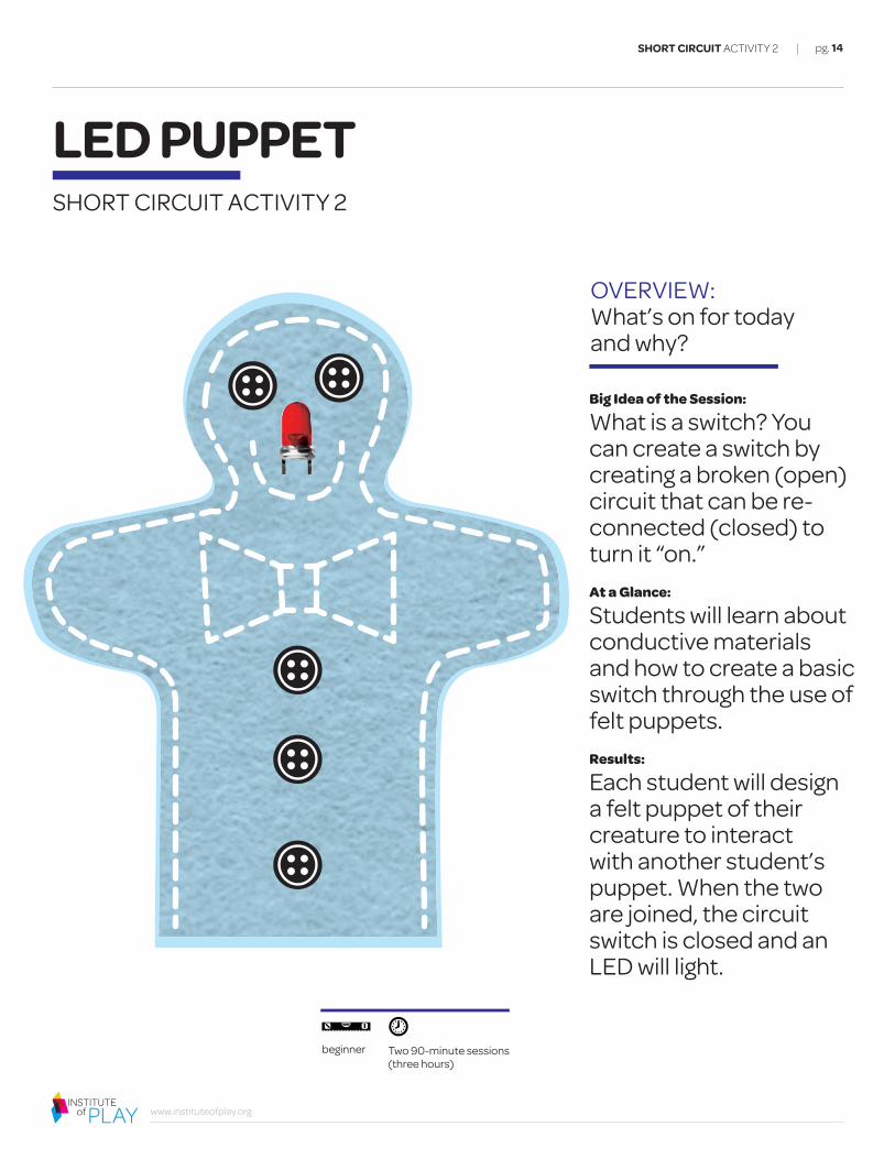
What is a switch? You can create a switch by creating a broken (open) circuit that can be re-connected (closed) to turn it “on.”At a Glance:
Students will learn about conductive materials and how to create a basic switch through the use of felt puppets.Results:
Each student will design a felt puppet of their creature to interact with another student’s puppet. When the two are joined, the circuit switch is closed and an LED will light.
SHORT CIRCUIT ACTIVITY 2
SHORT CIRCUIT ACTIVITY 2
LED PUPPET
Two 90-minute sessions (three hours)
beginner

CONTEXT & BACKGROUND
pg. 15
www.instituteofplay.org
DELIVERABLE:
One puppet that connects with another to turn on a light and complete a system.
SHORT CIRCUIT ACTIVITY 2
LED PUPPET
KEY TERMS: Definitions you need to know firstConductive fabricA fabric woven with silver threading, therefore giving it a conductive quality.
Conductive threadA type of thread that can conduct electricity, thereby making it possible to create “wearable” circuitry.
E-puppetA puppet made with electronics.
MultimeterA handheld device with a negative and a positive probe used to measure resistance (conductive or not conductive).
Soft circuitCombining electronics with fabric-based projects. Also known as electronic textiles or e-textiles.
SwitchAn electrical component that can break an electrical circuit, interrupting the current or diverting it from one conductor to another.
Student-made planning document including puppet and circuit design

BEFORE YOU BEGIN
pg. 16
www.instituteofplay.org
GETTING READY:Last minute tips
INSTRUCTIONAL RESOURCES: For more information
MATERIALS: What you’ll need
SHORT CIRCUIT ACTIVITY 2
LED PUPPET
Have a prototype of the circuit to show to the students with all components listed.
Have a prototype of the final product on hand to show the students.
Set up arts & crafts materials in one central location.
Have small bags prepared for each student with all needed components inside.
CHECK OUT SESSIONS 1 & 2of the Short Circuit Professional Development series
AN AMUSING VIDEO THAT USES THE SAME CONCEPT, BUT WITH THUMB WRESTLING AND SOUND:http://vimeo.com/12271372
http://soft-circuit.com/wp-content/uploads/2010/05/Tutorial_Peanut.pdf
http://www.youtube.com/watch?v=dwBjzdBimW0&feature=player_embedded
FOR EACH STUDENT YOU WILL NEED:
A sock
Scissors A method to connect electronics, such as any of the following:Conductive tape
Conductive thread/Glue gun
A Ziploc bag containing electronics: Alligator clips, conductive thread, conductive tape
3-volt battery
Four pieces of conductive fabric (one for each puppet, two to create the battery case)
1 or 2 LEDs
FOR THE GROUP YOU WILL NEED:
Felt and yarn (for crafting details)
Cardstock
Fabric for puppet “bodies”
Plastic “googly” eyes
Needle-nose pliers
Fabric markers and/or fabric paint
Fabric glue
Wire
Markers
Wire stripper Testing out the puppet with alligator clips before the circuit is finalized
Bookbinder's knot
STEP ONE:Pull 3-4" of the thread through the eye of the needle.
STEP TWO:Pierce the needle through the fibers of the thread.
STEP THREE:Using your thumb and forefinger, pull the pierced thread toward the eye of the needle.
STEP FOUR:Pull the other end of the thread until the knot is secure. Knot the bottom of the thread.

LESSON PLAN: Step by step implementation
pg. 17
www.instituteofplay.org
SHORT CIRCUIT ACTIVITY 2
LED PUPPETTHE PLAN
STEP 1Prototype Preview:
First, show off the circuit that includes all the components they’ll be using. Show them how to turn on the LED light by connecting the puppets. Next, show them the components housed in actual puppets. Let them know they’ll be making their own puppets and putting together the circuit. Explain that they won’t need any resistors, as the LEDs are approximately 3.3 volts each, and we’re using a 3-volt battery. Let them know they will design puppets that complement each other, and act as a switch to turn on the LED light once they are touching.
STEP 2Compoment Preview:
Hand out bags of components. Have the students experiment with the parts, and challenge them to get the circuit built with just their hands—no sewing yet!
STEP 3Design:
Hand out the cardstock that the students will use to create their puppets. After they’ve created and cut out a cardstock pattern, allow them to trace it and cut out the fabric puppet body. They can then decorate the puppets. After sewing is complete (step 6) the students can glue their puppets back on to their pattern, to reinforce the body.
STEP 4Prepare Conductive Materials:
Cut 24 inches of conductive thread for each puppet. Create a "battery pack" by attaching a half inch by two inch strip of conductive fabric to each side of the battery. This step is optional, but allows for the placement of the battery anywhere. After the battery pack is constructed, conductive thread can be sewn into either strip of fabric, to create positive and negative leads.
STEP 5First Puppet:
This puppet will provide the power from the battery pack. First, thread the needle using the bookbinder's knot (see below). Next, begin by looping the thread several times around the area where the positive battery contact will be placed. If you are using a battery pack, then loop the thread a few times through the fabric connected to the positive side. Next, do the same for the negative side of the battery pack. You will now have a positive and negative path leading from the battery. See the large elephant in the diagram below. Remember: the negative and positive paths must not intersect at any point! Depending on how you design your puppet, you may want these paths to end on pieces of foil, larger strips of conductive fabric, or simply knots of thread that create a contact point. This is up to you.
Image Credit: Soft Circuit
Note: The negative and positive sew paths must not intersect at any point
Positive PathNegative Path

LESSON PLAN: Step by step implementation
pg. 18
www.instituteofplay.org
SHORT CIRCUIT ACTIVITY 2
STEP 8Wrapping Up:
Now that you have two puppets, each with positive and negative paths leading to a battery or LED, it's time to make them light up! Simply touch the positive contact point of the battery puppet to the LED puppet. Then, connect the two negative contact points. If you've done everything correctly, you should see the LED light up! If not, make sure you've connected the puppets in the right way - negative to negative and positive to positive. Be sure you have the battery in the pack in the right way, and that you know which leg of the LED is which. If everything looks good, make sure that all connections are properly sewn. Press on each connection between your index finger and thumb, and see if the pressure makes a di�erence. You may need to make a stronger connection with the thread. If you have trouble, or you doubt your sewing skills, just add a blob of hot glue over the connection once you have it working. That will hold everything in place.
STEP 7Second Puppet:
This puppet will provide the light from an attached LED. First, thread the needle using the bookbinder's knot (see p. 16). Next, begin by looping the thread several times around positive (longer) leg of the LED. It might be a good idea to mark the positive leg with a black marker, so you can identify it later. It's easier to attach the thread to the legs of the LED if you gently twist them into spirals using needle-nose pliers. Next, do the same for the negative leg of the LED. You will now have a positive and negative path leading from the LED. See the small elephant in the diagram above. Remember: the negative and positive paths must not intersect at any point! Depending on how you design your puppet, you may want these paths to end on pieces of foil, larger strips of conductive fabric, or simply knots of thread that create a contact point. This is up to you.
THE PLAN cont.
LED PUPPET
Two completed puppets with LED light in the center of the heart:
Student-made circuit diagram of a switch to control an LED light with conductive fabric

TIPS & EVALUATION
pg. 19
www.instituteofplay.org
SHORT CIRCUIT ACTIVITY 2
LED PUPPET
REFLECTWorksheets: Have students complete both evaluation worksheets for this activity.
WRAP UPCircle Up: After the worksheets are completed, come together for a conversation to share these thoughts. Go around the room and have each student share something that they wrote in their self-reflection.
1. Use a digital (still) camera to take pictures that tell the story. Have the students use the story board as a reference, and take photos of the puppets in action. Then, print out the photos and use them to create a comic book. The students can use Photoshop or a similar image editing software to add captions, text, or other e�ects. This could also happen on screen, with the students posting the comic book to a webpage or blog.
2. Use a digital (still) camera and iMovie (or similar video editing software) to create a stop-motion animation of your puppets’ story. For best results, set the camera up on a tripod, and have students work in teams of two: one to take pictures while the other one poses the puppets. Uploading the photos to iMovie and putting them together with titles will give your puppets a finished look.
It may be best to decide ahead of time the best circuit building methods for your group: glue gun, fabric glue, or sewing.
Conductive fabric/tape/thread needs to be sewn/glued into the places of contact for the LED(s) to turn on (these patches will be visible).
The 3V battery will also need two pieces of conductive fabric (one on the + side, one on the —side).
TIPS:Additional implementation information
MOD THIS SESSION:Extending this activity
EVALUATUON:How did it go?
DEBUGGINGCircuit not working?Use this checklist to help you get to the bottom of your problem.
ª When creating the battery pack, make sure that the two pieces of conductive fabric attached to either side of the battery are not touching.
ª When using conductive thread, be sure to double knot the thread in order to secure a good connection. You won’t have a strong path for the current to flow if the knot is loose or not well connected to the fabric.
ª Be sure that the positive and negative thread paths do not touch at any point.
ª Once the LED legs are twisted, it will be hard to tell which is which. Marking one leg is a good idea.
ª When attaching thread to the LED, be sure to check each leg. The longer leg is positive. The shorter leg is negative. Follow your eyes along the path to the battery and make sure you’re attaching the right side.

pg. 20
www.instituteofplay.org
OVERVIEW: What’s on for today and why?
Big Idea of the Session:
We can hack technology that already exists and repurpose it in new ways. At a Glance:
Students will take apart greeting cards with sound and use the technology to recreate a boombox from a recycled cereal box. Results:
Students will create a new use for sound cards from greeting cards: A boombox made from a cereal box. The boombox will include a dial to “hack” the sound.
SHORT CIRCUIT ACTIVITY 3
SHORT CIRCUIT ACTIVITY 3
CEREAL BOOMBOX
Two 90-minute sessions (three hours)
intermediate

CONTEXT & BACKGROUND
pg. 21
www.instituteofplay.org
DELIVERABLE:
Students will be assessed with their final product, a “boombox” made out of a cereal box and a sound card taken from a greeting card. A potentiometer knob to “bend” the sound is needed. Cereal boxes are decorated to their liking.
SHORT CIRCUIT ACTIVITY 3
CEREAL BOOMBOX
KEY TERMS: Definitions you need to know firstSolderA fusible metal alloy used to join together metal pieces.
Soldering ironA tool used for melting solder and applying it to metals that are to be joined.
DesolderingThe removal of solder and components from a circuit for troubleshooting, repair purposes, salvaging components, or hacking.
Resistor An electrical component that limits or regulates the flow of electrical current in an electronic circuit.
CapacitorAn electrical component that stores electric current for releasing it at a specific time or rate but does not generate it.
PotentiometerA three-terminal resistor with a sliding contact that forms an adjustable voltage divider. If only two terminals are used (one side and the wiper), it acts as a variable resistor or rheostat.
Circuit-bendingThe creative customization of the circuits within electronic devices such as low voltage, battery-powered guitar e�ects, children's toys and small digital synthesizers to create new musical or visual instruments and sound generators.
Middle: A potentiometerBottom: A typical sound module taken from a greeting card

BEFORE YOU BEGIN
pg. 22
www.instituteofplay.org
INSTRUCTIONAL RESOURCES: For more information
MATERIALS: What you’ll need
CEREAL BOOMBOX
SHORT CIRCUIT ACTIVITY 3
GETTING READY:Last minute tipsHave a prototype of the circuit to show to the students with all components listed.
This activity works well when there are three separate “stations” (or work tables) for working: a soldering station, a cutting/taping boxes station, and a painting/decorating station. Keeping these materials separate minimizes the chances of messes, and gives the students a sense of progress as they move along. If possible, set up the three areas (with the corresponding materials) and ample space for everyone involved.
CHECK OUT SESSIONS 1 & 2of the the Short Circuit Professional Development series
ANOTHER VERSION OF THIS ACTIVITY:http://www.instructables.com/id/Circuit-Bending-Audio-Greeting-Cards/
HOW TO SOLDER:http://www.aaroncake.net/electronics/solder.htm
HOW TO DESOLDER (with photos): http://www.epemag.wimborne.co.uk/desolderpix.htm
FOR EACH STUDENT YOU WILL NEED:
Empty cereal box
A sound/ music greeting card - must be either American Greetings or Carlton Cards.
A potentiometer (between 50 - 100 K) http://www.radioshack.com/product/index.jsp?productId=2062355
Two electrical wires
FOR THE GROUP YOU WILL NEED:
Solder
Soldering irons
Desoldering pumps or desolder (copper) braid
Paint
Markers
Scissors
Box-cutting knives
Glue guns
Paper tape
Electrical tape
Wire stripper
1. Opening the greeting card2. Soldering two wires to potentiometer3. Desoldering using braid 4. Soldering wires into card

LESSON PLAN: Step by step implementation
THE PLAN
pg. 23
www.instituteofplay.org
SHORT CIRCUIT ACTIVITY 3
STEP 5Diagram your Design:
Using Worksheet 1, have students sketch the diagram of their design. This document can be used as a final assessment of students’ understanding. Be sure to have them label each of the components.
STEP 6Choose your Station:
If there are not enough soldering irons for everyone to start out doing this, it’s a good idea to ask for volunteers to start at another station, such as cutting out a hole for the speaker, and then painting/decorating. Soldering can be done after this process, if desired. That way, everyone can move from station to station and not be crowding around one table at all times.
STEP 3Open Sesame:
Have students carefully open up their greeting cards to expose the circuitry. Ask, “What do you see?” Explain the components that they see. (A good reference: http://www.instructables.com/id/Circuit-Bending-Audio-Greeting-Cards/step2/Open-and-Test/) Have students experiment to figure out how the switch works to start the music.
STEP 4Bend it:
Explain that resistors hold the energy back from being given out all at once. It regulates the electricity that goes through. Say, “You can ‘bend’ the music you hear by licking a finger, and touching the soldered area around the resistors.” Try it! Lick a finger and touch the soldered area around the resistors. (We promise – you won’t get hurt.) To regulate that “bent” sound, we will be replacing the resistor with a potentiometer. This is a device with a dial that can regulate the flow, acting as a variable resistor.
STEP 1Show and Tell:
Show students your prototype of a cereal boombox. Demonstrate how it works – by pressing the “on” button it plays a song, and by turning a knob while pressing the button it “bends” the song. Explain that everyone is going to create their own cereal boombox today.
STEP 2Happy Birthday!:
Give each student a greeting card. Say, “You are receiving a very special card today. Not only is it a great card to receive, but it’s a great card to hack!” Allow students to play around with the cards for a little while. They will want to share which one they have, experiment with opening/closing, etc.
CEREAL BOOMBOX

pg. 24
www.instituteofplay.org
LESSON PLAN: Step by step implementation
SHORT CIRCUIT ACTIVITY 3
STEP 9Boombox Building:
Each student will have the ultimate decision about placement on their cereal box. They will need to cut holes for the on/o� switch, the potentiometer, and the speaker. Around the speaker, it is good to include a cone-shaped casing to amplify the sound.
STEP 10Painting with Passion:
The final step is to add color and “branding” to the boombox. Students should focus on how to design an appealing package to consumers.
STEP 8Make a Switch:
To make your sound card work in the boom box, you’ll need to make a switch to start the music. In the greeting card, this was created by putting a piece of paper between two parts of the circuitry, thus cutting the circuit and keeping the music “o�.” When the card was opened, the paper was pulled, and the circuitry was once again reconnected. You have to create a similar switch. Create an on/o� “button” using cardboard, fabric, or something else to press. Bend the wiring upwards, so that it won’t connect with the circuitry unless this button is pressed. It will take some time to figure out the best configuration.
STEP 7 Solder Time:
We need to desolder the resistor and replace it with the potentiometer (a variable resistor). To desolder, hold the soldering iron to one contact of the resistor. When the solder melts, take your soldering pump and pull it away. (You can also use desoldering braid, which is made out of copper and will have the same e�ect.) Do the same to the other side. Remember how it was connected, because you’ll need to solder back in the potentiometer! The next step is to solder two wires (positive and negative sides) to the potentiometer. These wires will then be soldered in where the resistor was taken out. To solder, hold the soldering wire to the place where you will need it, and carefully melt it into place with the soldering iron. Demonstrate the entire process with one student’s sound card, so everyone can watch.
THE PLAN cont.
CEREAL BOOMBOX
A student carefully solders a potentiometer

pg. 25
www.instituteofplay.org
REFLECTThese questions can be used by Mentors to reflect on the e�ectiveness of the activity in relation to the learning goals:
Was each student able to create his or her own boombox?
Was each student able to create a comprehensive diagram of the boombox, including labels for all components (worksheet 1)?
Were students able to identify the components in the sound card?
What was the biggest challenge for the students, in using the materials?
WRAP UPSelf-Reflection: Have students take a moment to think about the work they’ve done for this activity, and what they’d like to do in the future. Use Worksheet 3 for this activity.
Circle Up: After the worksheets are completed, come together for a conversation to share these thoughts. Go around the room and have each student share something that they wrote in their self-reflection.
To extend this activity, give students more than one sound card and have them create a boombox with several “on” buttons and dials.
Not every student will want to “bend” the sound with a potentiometer. We recommend letting students make their own design choices; everyone will still learn the components involved, but then make their own creative decisions.
TIPS:Additional implementation information
MOD THIS SESSION:Extending this activity
EVALUATUON:How did it go?
SHORT CIRCUIT ACTIVITY 3
CEREAL BOOMBOXTIPS & EVALUATION
DEBUGGINGCircuit not working?Use this checklist to help you get to the bottom of your problem.
ª Be careful when desoldering. Too much heat may damage the circuit board from the card. If you can’t seem to get the resistor out right away, pause in between attempts so heat doesn’t build up.
ª Soldering to potentiometer legs can be tough. If the joints are loose, the circuit won’t function properly. Try adding a blob of hot glue after you secure the connections. This will allow you to manipulate the potentiometer without the soldered joint coming loose.

www.instituteofplay.org
pg. 26SHORT CIRCUIT ACTIVITY 4
LED FLASHLIGHT
Big Idea of the Session:
We can use cheap components to make a useful everyday object.At a Glance:
Students will create a flashlight out of cardboard, LEDs, a battery, a button, and some wire.Results:
Students will create a cheap, portable, and bright flashlight that uses very little power.
OVERVIEW: What’s on for today and why?
SHORT CIRCUIT ACTIVITY 4
One 120-minute session (two hours)
beginner

pg. 27
www.instituteofplay.org
SHORT CIRCUIT ACTIVITY 4
LED FLASHLIGHT
DELIVERABLE:
Students will be assessed with their final product, flash-light that is powered by a 9V battery and made of LEDs and a button. The flashlight housings are decor–ated to their liking.
CONTEXT & BACKGROUND
SolderA fusible metal alloy used to join together metal pieces.
Soldering ironA tool used for melting solder and applying it to metals that are to be joined.
BatteryA container consisting of one or more cells, in which chemical energy is converted into electricity and used as a source of power.
Button (momentary push-button switch)A button that when pressed closes and completes a circuit, by allowing current to flow.
LEDA light-emitting diode (LED) is a semiconductor device that emits visible light when an electric current passes through it.
Electric circuitAn unbroken path along which an electric current exists or is intended to flow.
MultimeterAn instrument designed to measure electric current, voltage, and usually resistance, typically over several ranges of value.
KEY TERMS: Definitions you need to know first
Above: Various types of LEDsBelow: A diagram of a closed and open circuit
OFF ON
+ +
+ +
- -
- -
3v 3v

pg. 28
www.instituteofplay.org
SHORT CIRCUIT ACTIVITY 4
LED FLASHLIGHT
WIRING UP MULTIPLE LEDS IN SERIES:http://www.instructables.com/id/LEDs-for-Beginners/step7/Wiring-up-multiple-LEDs-in-series/
HOW TO SOLDER:http://www.aaroncake.net/electronics/solder.htm
HOW TO DESOLDER (with photos): http://www.epemag.wimborne.co.uk/desolderpix.htm
Have a prototype of the circuit to show to the students with all components listed.
Have a prototype of the final product on hand to show the students.
Set up the soldering irons ahead of time, spread apart, to allow students space to work without interfering with each other.
Set up arts & crafts materials in one central location.
Have small bags prepared for each student with all needed components inside (9V battery, three LEDs, wire, and button/switch).
MATERIALS: What you’ll need
INSTRUCTIONAL RESOURCES: For more information
GETTING READY:Last minute tips
BEFORE YOU BEGIN
FOR EACH STUDENT YOU WILL NEED:
9V (volt) battery
Three LEDs, any color approximately 3.3V each
Momentary push-button switch (normally open)
FOR THE GROUP YOU WILL NEED:
Solder
Soldering irons
Wire
Cardboard / cardstock
Desoldering pumps or desolder (copper) braid
Paint
Markers
Scissors
Box-cutting knives
Glue guns
Paper tape
Electrical tape
Wire stripper
A student-made diagram of the circuit inside the LED flashlight

pg. 29
www.instituteofplay.org
SHORT CIRCUIT ACTIVITY 4
LED FLASHLIGHT
STEP 1Prototype Preview:
First, show off the circuit that includes all the components they’ll be using.Show them how to turn on the lights by pressing the button. Next, show them the components housed in a decorated cardboard tube. Let them know they’ll be making their own flashlights and putting together the circuit. Explain that they won’t need any resistors, as the LEDs are approximately 3.3 volts each, and we’re using a 9 volt battery. Explain that this method (shown pg. 28) is called wiring things “in series.”
STEP 2Prototype Challenge:
Hand out bags of components. Have the students experiment with the parts, and challenge them to get the circuit built with just electrical tape—no solder yet!
STEP 3Design:
Hand out the cardboard and/or cardstock that the students will use to create their flashlights. Allow them to decorate them, but not tape them together yet. They’ll need to put in their circuit before the flashlight is sealed. Make sure they put a hole in the housing to make room for the button or switch.
STEP 4Soldering:
Allow the students to take their working, but taped, circuits over to the soldering stations. Remind them to double check the LED’s to make sure they’re placed in the right direction before soldering. Students should verify that their circuit works (via button press) before leaving the soldering stations.
STEP 5Putting it All Together:
Students will seal up their designs, taping or hot gluing their circuit inside their cardboard housing.
STEP 6Double Checking:
Using Worksheet 1, have students sketch the diagram of their circuit. This document can be used as a final assessment of students’ understanding. Be sure to have them label each of the components.
LESSON PLAN: Step by step implementation
THE PLAN
TIPS & EVALUATION
pg. 30
www.instituteofplay.org
SHORT CIRCUIT ACTIVITY 4
LED FLASHLIGHT
REFLECTThese questions can be used by Mentors to reflect on the e�ectiveness of the activity in relation to the learning goals:
Was each student able to create his or her own flashlight?
Was each student able to create a comprehensive diagram of the flashlight, including labels for all components (worksheet 1)?
What was the biggest challenge for the students, in using the materials?
WRAP UPSelf-Reflection & Review: Have students take a moment to think about the work they’ve done for this activity and what they’ve learned. Use Worksheet 3 for this activity.
Circle Up: After the worksheets are completed, come together for a conversation to share these thoughts. Go around the room and have each student share something that they wrote in their self-reflection.
Give students the option of using different types of batteries and LEDs. This calculator is helpful to figure out the number of LEDs and resistors needed for varying amounts of voltage when soldering LEDs in series: http://led.linear1.org/led.wiz
Although the circuit is simple, things can go wrong. Make sure to explain the difference between the legs on an LED (longer leg = positive and shorter leg = negative). Make sure students know this before soldering their circuit together.
After students solder together their circuit, and confirm that it’s working, tape it! As seen in the diagram on pg. 28, electrical tape around soldered joints will make this flashlight last a lot longer. It will also help preserve the joints if the students need to manipulate the circuit when inserting into the cardboard housing.
TIPS:Additional implementation information
MOD THIS SESSION:Extending this activity
EVALUATUON:How did it go?
DEBUGGINGCircuit not working?Use this checklist to help you get to the bottom of your problem.
ª Make sure the LEDs are connected properly before soldering them. The longer leg is positive and the shorter leg is negative. Also, make sure the LEDs are functioning properly. Test out the circuit with alligator clips to make sure current flows from the battery, through the switch, and through the LEDs. If everything works, mark the LED legs so no mistakes are made during soldering.
ª Soldering onto the switch contacts can be tough. If the joints are loose, the circuit won’t function properly. Try adding a blob of hot glue after you secure the connections. This will allow you to manipulate the switch without the soldered joint coming loose.
pg. 31
www.instituteofplay.org
OVERVIEW: What’s on for today and why?
Big Idea of the Session:
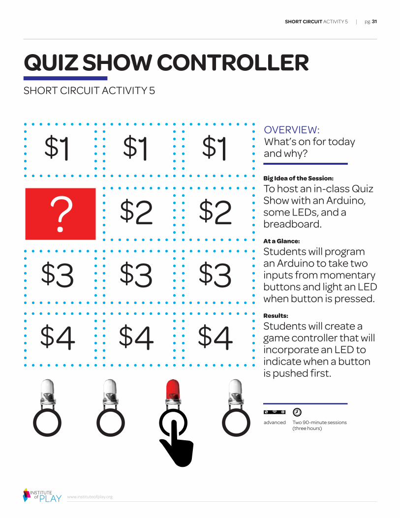
To host an in-class Quiz Show with an Arduino, some LEDs, and a breadboard. At a Glance:
Students will program an Arduino to take two inputs from momentary buttons and light an LED when button is pressed.Results:
Students will create a game controller that will incorporate an LED to indicate when a button is pushed first.
SHORT CIRCUIT ACTIVITY 5
QUIZ SHOW CONTROLLERSHORT CIRCUIT ACTIVITY 5
Two 90-minute sessions (three hours)
advanced
$1
?$3
$4
$1
$2
$3
$4
$1
$2
$3
$4

CONTEXT & BACKGROUND
pg. 32
www.instituteofplay.org
DELIVERABLE:
Students will be assessed with their final product—a quiz show controller and accompanying housing, which can be decorated to the students’ liking.
SHORT CIRCUIT ACTIVITY 5
QUIZ SHOW CONTROLLER
KEY TERMS: Definitions you need to know firstSolderA fusible metal alloy used to join together metal pieces.
Soldering ironA tool used for melting solder and applying it to metals that are to be joined.
Momentary switch / Push button A button that when pressed closes and completes a circuit, by allowing current to flow.
LEDA light-emitting diode (LED) is a semiconductor device that emits visible light when an electric current passes through it.
Electric circuitAn unbroken path along which an electric current exists or is intended to flow.
PotentiometerAn adjustable voltage divider, a “pot” sends variable amounts of voltage to the Arduino.
Data variablesHolds a specific value inside of the Arduino. In this case, a musical note.
Student-made circuit diagram of a switch to control an LED light for a controller

BEFORE YOU BEGIN
pg. 33
www.instituteofplay.org
GETTING READY:Last minute tips
INSTRUCTIONAL RESOURCES: For more information
MATERIALS: What you’ll need
CHECK OUT SESSIONS 2 AND 3 of the the Short Circuit Professional Development series
SEE SCHEMATIC AND CODE on page 35
Have a prototype of the circuit to show to the students with all components listed (see below).
Have a prototype of the final product on hand to show the students.
Set up arts & crafts materials in one central location.
FOR EACH STUDENT YOU WILL NEED:
Pen
Note Cards
FOR THE GROUP YOU WILL NEED:
Arduino
Wire
Electrical tape
Wire stripper
Resistors
Breadboard
LEDs
Buttons
SHORT CIRCUIT ACTIVITY 5
QUIZ SHOW CONTROLLER
Student-made list of common components used during Short Circuit
LESSON PLAN: Step by step implementation
pg. 34
www.instituteofplay.org
STEP 5Code:
In Arduino, set three constant integers for the three LEDs and one analog pin that acts like a potentiometer (since there are three different resistors to measure). Set pins 7-9 to output to the LEDs when triggered. In the loop, read the analog values and turn on the corresponding LED. An “if/else” statement or a case switch can be used to check for the three di�erent conditions (depending on which button/LED is triggered). An example of the code is provided.
STEP 3Play:
Try a few rounds of the game show. Have different groups challenge each other.
STEP 3Hardware:
Gather four resistors of varying values, 3 momentary switches, and 3 LEDs of any color.
STEP 4Breadboard:
Students will hook three of the four resistors up to a breadboard, and power them by the 5V line from the Arduino. Each resistor will be connected to a switch and an LED. The fourth resistor will be placed in analog pin 3 and GND (ground). It will also share a ground with the three other resistors. Since each resistor is di�erent, you can uniquely identify each switch by the change of the current.
STEP 1Plan:
Building upon skills learned in previous classes, students will build a simple circuit that lights up an LED with a momentary switch. Begin your planning the circuit by looking at the circuit diagram.
STEP 2Content:
Have the students create quiz cards for the game. They can compile questions / flash cards relating to class and homework—or even memes from the internet.
SHORT CIRCUIT ACTIVITY 5
QUIZ SHOW CONTROLLERTHE PLAN

TIPS & EVALUATION
pg. 35
www.instituteofplay.org
SHORT CIRCUIT ACTIVITY 5
QUIZ SHOW CONTROLLER
PARTS4 resistors of different values
3 normally open push-button switches
3 LEDs of any color
SUMMARYA three button quiz show buzzer. The first button pushed lights corresponding LED for two seconds (for those two seconds the remaining buttons will not light LEDs).
R1 pulls analog pin 3 to 0 when all switches are open. R2-R4 change the current flow so you can uniquely identify each switch.
SCHEMATIC3 Button Quiz Show Buzzer (analog)
CODEconst int analogPin = 3; // potentiometer (middle terminal) connected to pin 3// outside leads to ground and +5Vint val = 0; // variable to store the value readconst int red = 7; // red LED connected to pin 7const int green = 8; // green LED connected to pin 8const int orange = 9; // orange LED connected to pin 9void setup(){Serial.begin(9600); // setup serialpinMode(red, OUTPUT); // sets pins 7-9 as outputpinMode(green, OUTPUT);pinMode(orange, OUTPUT);}void loop(){val = analogRead(analogPin); // read input analog pin 3
// check values, determines which //switch is pushed
if(val >= 506 && val <= 516){digitalWrite(red, HIGH); // turns red LED ondigitalWrite(green, LOW); // turns green LED o�digitalWrite(orange, LOW);delay(2000); // delay the program for two seconds}// check values, determines which switch is pushedelse if(val >= 236 && val <= 243){digitalWrite(green, HIGH);digitalWrite(red, LOW);digitalWrite(orange, LOW);delay(2000);}// check values, determines which switch is pushedelse if(val >= 929 && val <= 934){digitalWrite(orange, HIGH);digitalWrite(red, LOW);digitalWrite(green, LOW);delay(2000);}// if above three conditions fail, all LEDs turn o�else{digitalWrite(red, LOW);digitalWrite(green, LOW);digitalWrite(orange, LOW);}}
3 Button Quiz Show Buzzer (analog) Parts • 4 resistors all must be different values • 3 normally open push button switches • 3 LEDs of any color Summary A three button quiz show buzzer. The first button pushed lights corresponding LED for two seconds (for those two seconds the remaining buttons will not light LEDs) R1 pulls analog pin 3 to 0 when all switches are open. R2-R4 change the current flow so you can uniquely identify each switch.
R1 R2 R3 R4
Quiz Show Schematic
Arduino
ICSP
S1
S1
Q1
http://arduino.berlios.de
Digital
SV1
PWR
1
RXTX
AREF
GN
D
PWM
0PW
M0
PWM
1
PWM
2
1C1
USB
X1 POWER5V Gnd 9V
Analog In0 1 2 3 4 5
R1R2
SPST
SPST
SPST
R3 R4
511
731
401
621
39 28 1 0

TIPS & EVALUATION
pg. 36
www.instituteofplay.org
SHORT CIRCUIT ACTIVITY 5
QUIZ SHOW CONTROLLER
REFLECTWorksheets: Have students complete all evaluation worksheets for this activity.
WRAP-UPCircle Up: After the worksheets are completed, come together for a conversation to share these thoughts. Go around the room and have each student share something that they wrote in their self-reflection.
Momentary buttons can be made out of almost anything. Go to a 99 cents store and seek out items that might make great buttons (staplers, hair clips, random toys).
Try adding sound! Look at the Noise Machine module for more information.
If soldering, make sure to build it on a breadboard first to make sure the circuit works!
Although the circuit is simple, things can go wrong. Make sure to explain the difference between the legs on an LED (longer leg = positive and shorter leg = negative). Make sure students know this before soldering their circuit together.
TIPS:Additional implementation information
MOD THIS SESSION:Extending this activity
EVALUATUON:How did it go?
DEBUGGINGCircuit not working?Use this checklist to help you get to the bottom of your problem.
ª Be sure that the LEDs are inserted into the breadboard properly. The long legs are positive and the shorter legs are negative.
ª If everything looks good on the breadboard, check your code! Be sure the pins that are used (7-9 in the sample code) match the pins on your Arduino. If they don’t, change your wiring or change your code.

pg. 37
www.instituteofplay.org
OVERVIEW: What’s on for today and why?
Big Idea of the Session:
A reimagining of a traditional activity with simple circuits and papercraft designs. At a Glance:
Students will build papercraft sculptures from pre-existing papercraft designs and light them with their choice of LEDs.Results:
Students will create Jack-o’-lanterns out unique custom ideas.
SHORT CIRCUIT ACTIVITY 6
PAPERCRAFT JACK-O’-LANTERNSHORT CIRCUIT ACTIVITY 6
One 120-minute session (two hours)
beginner

CONTEXT & BACKGROUND
pg. 38
www.instituteofplay.org
SHORT CIRCUIT ACTIVITY 6
DELIVERABLE:
Students will be assessed with their final product, a papercraft structure that lights up with an LED. The papercraft structures are decorated to their liking.
PAPERCRAFT JACK-O’-LANTERN
KEY TERMS: Definitions you need to know firstSolderA fusible metal alloy used to join together metal pieces.
Soldering ironA tool used for melting solder and applying it to metals that are to be joined.
BatteryA container consisting of one or more cells, in which chemical energy is converted into electricity and used as source of power.
LEDA light-emitting diode (LED) is a semiconductor device that emits visible light when an electric current passes through it.
Electric circuitAn unbroken path along which an electric current exists or is intended to flow.
MultimeterAn instrument designed to measure electric current, voltage, and usually resistance, typically over several ranges of value.
A papercraft arcade machine: on and off

BEFORE YOU BEGIN
pg. 39
www.instituteofplay.org
GETTING READY:Last minute tips
INSTRUCTIONAL RESOURCES: For more information
MATERIALS: What you’ll need
Have a prototype of the circuit to show to the students with all components listed (see below).
Have a prototype of the final product on hand to show the students.
Set up the soldering irons ahead of time, spread apart, to allow students space to work without interfering with each other.
Set up arts & crafts materials in one central location.
Have small bags prepared for each student with all needed components inside (9V battery, three LEDs, and wire).
SHORT CIRCUIT ACTIVITY 6
CHECK OUT SESSIONS 1 & 2 of the the Short Circuit Professional Development series
WIRING UP MULTIPLE LEDS IN SERIES:http://www.instructables.com/id/LEDs-for-Beginners/step7/Wiring-up-multiple-LEDs-in-series/
HOW TO SOLDER:http://www.aaroncake.net/electronics/solder.htm
HOW TO DESOLDER (with photos): http://www.epemag.wimborne.co.uk/desolderpix.htm
PAPERCRAFT DESIGNS: http://www.epemag.wimborne.co.uk/desolderpix.htm
FOR EACH STUDENT YOU WILL NEED:
9V (volt) battery
Three LEDs, any color, approximately 3.3V each
Papercraft pattern (downloaded from the Internet, see Instructional Resources section)
FOR THE GROUP YOU WILL NEED:
Solder
Soldering irons
Wire
Desoldering pumps or desolder (copper) braid
Markers
Scissors
Box-cutting knives
Double-sided tape
Electrical tape
Wire stripper
PAPERCRAFT JACK-O’-LANTERN
A common papercraft pattern - caution should be used when cutting out the smaller pieces

LESSON PLAN: Step by step implementation
THE PLAN
pg. 40
www.instituteofplay.org
SHORT CIRCUIT ACTIVITY 6
STEP 5Putting it All Together:
Students will seal up their designs, taping or hot gluing their circuit inside their papercraft housing.
STEP 6Ready for Display:
This is made to stay on—and be displayed in a window or on a desk. The 9V battery will last a long time, but it is best to disconnect it when not in use.
STEP 3Design:
Hand out the papercraft designs. Allow them to decorate them, but not put them together yet. They’ll need to place their circuit inside before the object is sealed. Make sure they put a hole in the housing to make room for the lights.
STEP 4Soldering:
Allow the students to take their working, but taped, circuits over to the soldering stations. Remind them to double check the LEDs to make sure they’re placed in the right direction before soldering. Students should verify that their circuit works before leaving the soldering stations.
STEP 1Prototype Preview:
First, show off the circuit that includes all the components they’ll be using. Next, show them the components housed in a decorated papercraft structure. Let them know they’ll be making their own papercraft characters and putting together the circuit. Explain that they won’t need any resistors, as the LEDs are approximately 3.3 volts each, and we’re using a 9 volt battery. Explain that this method is called wiring things “in series.”
STEP 2Prototype Challenge:
Hand out bags of components. Have the students experiment with the parts, and challenge them to get the circuit built with just electrical tape—no solder yet!
PAPERCRAFT JACK-O’-LANTERN

TIPS & EVALUATION
pg. 41
www.instituteofplay.org
SHORT CIRCUIT ACTIVITY 6
PAPERCRAFT JACK-O’-LANTERN
REFLECTWorksheets: Have students complete all 3 evaluation worksheets for this activity.
WRAP UPCircle Up: After the worksheets are completed, come together for a conversation to share these thoughts. Go around the room and have each student share something that they wrote in their self-reflection.
Give students the option of using different types of batteries and LEDs. This calculator is helpful to figure out the number of LEDs and resistors needed for varying amounts of voltage when soldering LEDs in series: http://led.linear1.org/led.wiz
Try to find more papercraft designs (especially Minecraft-inspired ones): http://minecraftpapercraft.com/
Or make your own designs:PePaKuRahttp://www.tamasoft.co.jp/pepakura-en/
Google Sketch-up http://sketchup.google.com/download/
Although the circuit is simple, things can go wrong. Make sure to explain the difference between the legs on an LED (longer leg = positive and shorter leg = negative). Make sure students know this before soldering their circuit together.
TIPS:Additional implementation information
MOD THIS SESSION:Extending this activity
EVALUATUON:How did it go?
DEBUGGINGCircuit not working?Use this checklist to help you get to the bottom of your problem.
ª Make sure the LEDs are connected properly before soldering them. The longer leg is positive and the shorter leg is negative. Also, make sure the LEDs are function properly. Test out the circuit with alligator clips to make sure current flows from the battery and through the LEDs. If everything works, mark the LED legs so no mistakes are made during soldering.

pg. 42
www.instituteofplay.org
OVERVIEW: What’s on for today and why?
Big Idea of the Session:
To turn the Arduino into a musical device that plays notes from its code. At a Glance:
Students will program an Arduino from a sound output tutorial and create their own speakers from piezos and paper cups. Results:
Students will create their own sound device that plays melodies from their favorite songs/games.
SHORT CIRCUIT ACTIVITY 7
SHORT CIRCUIT ACTIVITY 7
NOISE MACHINE
One 90-minute session beginner

CONTEXT & BACKGROUND
pg. 43
www.instituteofplay.org
SHORT CIRCUIT ACTIVITY 7
NOISE MACHINE
DELIVERABLE:
Students will be assessed with their final product, a speaker connected to an Arduino microcontoller that plays a song they wrote or sequenced. The speaker housings are decorated to their liking.
KEY TERMS: Definitions you need to know firstSolderA fusible metal alloy used to join together metal pieces.
Soldering ironA tool used for melting solder and applying it to metals that are to be joined.
PiezoA simple speaker with really low output.
Electric circuitAn unbroken path along which an electric current exists or is intended to flow.
Data variablesHolds a specific value inside of the Arduino. In this case, a musical note.
The speaker is attached to the bottom of a cup, which acts as an amplifier
BEFORE YOU BEGIN
pg. 44
www.instituteofplay.org
GETTING READY:Last minute tips
INSTRUCTIONAL RESOURCES: For more information
MATERIALS: What you’ll need
SHORT CIRCUIT ACTIVITY 7
NOISE MACHINE
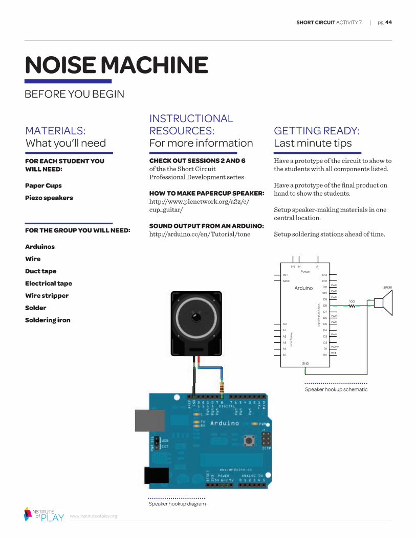
Speaker hookup schematic
Have a prototype of the circuit to show to the students with all components listed.
Have a prototype of the final product on hand to show the students.
Setup speaker-making materials in one central location.
Setup soldering stations ahead of time.
CHECK OUT SESSIONS 2 AND 6 of the the Short Circuit Professional Development series
HOW TO MAKE PAPERCUP SPEAKER:http://www.pienetwork.org/a2z/c/cup_guitar/
SOUND OUTPUT FROM AN ARDUINO: http://arduino.cc/en/Tutorial/tone
FOR EACH STUDENT YOU WILL NEED:
Paper Cups
Piezo speakers
FOR THE GROUP YOU WILL NEED:
Arduinos
Wire
Duct tape
Electrical tape
Wire stripper
Solder
Soldering iron
Speaker hookup diagram
SPKR1 PWM
PWM
PWM
PWM
PWM
PWM
PWM¹
RXº
RST
AREF
A0 D5
A2 D3
A4 D1
A1 D4
A3 D2
A5 D0
GND
Analog Input
Dig
ital I
nput
/Out
put
100
Vin
Power
Vin5V3V3
Arduino D11
D13
D9
D7
D10
D12
D8
D6

LESSON PLAN: Step by step implementation
THE PLAN
pg. 45
www.instituteofplay.org
SHORT CIRCUIT ACTIVITY 7
NOISE MACHINE
#include "pitches.h"int melody[] = {NOTE_C4, NOTE_G3,NOTE_G3, NOTE_
A3, NOTE_G3,0, NOTE_B3, NOTE_C4};int noteDurations[] = { 4, 8, 8, 4,4,4,4,4 };void setup() {for (int thisNote = 0; thisNote < 8;
thisNote++) {int noteDuration = 1000/
noteDurations[thisNote];tone(8, melody[thisNote],noteDuration);int pauseBetweenNotes = noteDuration
* 1.30;delay(pauseBetweenNotes);noTone(8);
}}void loop() {}
STEP 3Connect:
Connect one terminal of your speaker to digital pin 8 through a 100 ohm resistor.Connect the other terminal to ground. Consult the diagram or schematic on page 44 for more help.
STEP 4Code:
The students will copy the code below and play the the melody that comes with the example. For commented code, please check the Arduino link on page 44. The code can be downloaded from there, as well. This will save some typing in the classroom, if that is a concern.
STEP 1Setup:
Set up an Arduino speaker prototype and play a melody for the students. It’s best to play something simple that they know, like Twinkle Twinkle Little Star or the Super Mario Bros. theme.
STEP 2Soldering:
Solder to the positive and negative wires of the speaker, leaving enough slack to be able to place the speaker far away from the Arduino, if desired. A completed circuit,
ready for testing

pg. 46
www.instituteofplay.org
SHORT CIRCUIT ACTIVITY 7
#define NOTE_B6 1976#define NOTE_C7 2093#define NOTE_CS7 2217#define NOTE_D7 2349#define NOTE_DS7 2489#define NOTE_E7 2637#define NOTE_F7 2794#define NOTE_FS7 2960#define NOTE_G7 3136#define NOTE_GS7 3322#define NOTE_A7 3520#define NOTE_AS7 3729#define NOTE_B7 3951#define NOTE_C8 4186#define NOTE_CS8 4435#define NOTE_D8 4699#define NOTE_DS8 4978
STEP 5Make:
The sound coming from the speaker will be very faint and need some manual amplification. Tape the piezo onto the bottom of a cup to create a passive “speaker horn.”
STEP 6Hack:
Find tabs of famous 8-bit era game melodies and apply them to the code. The students will replace the notes from the tutorial and make their own music.
#define NOTE_G3 196#define NOTE_GS3 208#define NOTE_A3 220#define NOTE_AS3 233#define NOTE_B3 247#define NOTE_C4 262#define NOTE_CS4 277#define NOTE_D4 294#define NOTE_DS4 311#define NOTE_E4 330#define NOTE_F4 349#define NOTE_FS4 370#define NOTE_G4 392#define NOTE_GS4 415#define NOTE_A4 440#define NOTE_AS4 466#define NOTE_B4 494#define NOTE_C5 523#define NOTE_CS5 554#define NOTE_D5 587#define NOTE_DS5 622#define NOTE_E5 659#define NOTE_F5 698#define NOTE_FS5 740#define NOTE_G5 784#define NOTE_GS5 831#define NOTE_A5 880#define NOTE_AS5 932#define NOTE_B5 988#define NOTE_C6 1047#define NOTE_CS6 1109#define NOTE_D6 1175#define NOTE_DS6 1245#define NOTE_E6 1319#define NOTE_F6 1397#define NOTE_FS6 1480#define NOTE_G6 1568#define NOTE_GS6 1661#define NOTE_A6 1760#define NOTE_AS6 1865
LESSON PLAN: cont.To make the pitches.h file, click on the "new tab" button in the upper right hand corner of the window.
Then type out the following code, or copy and paste from tutorial link under Instructional Resources.
#define NOTE_B0 31#define NOTE_C1 33#define NOTE_CS1 35#define NOTE_D1 37#define NOTE_DS1 39#define NOTE_E1 41#define NOTE_F1 44#define NOTE_FS1 46#define NOTE_G1 49#define NOTE_GS1 52#define NOTE_A1 55#define NOTE_AS1 58#define NOTE_B1 62#define NOTE_C2 65#define NOTE_CS2 69#define NOTE_D2 73#define NOTE_DS2 78#define NOTE_E2 82#define NOTE_F2 87#define NOTE_FS2 93#define NOTE_G2 98#define NOTE_GS2 104#define NOTE_A2 110#define NOTE_AS2 117#define NOTE_B2 123#define NOTE_C3 131#define NOTE_CS3 139#define NOTE_D3 147#define NOTE_DS3 156#define NOTE_E3 165#define NOTE_F3 175#define NOTE_FS3 185
NOICE MACHINE THE PLAN
pg. 47
www.instituteofplay.org
SHORT CIRCUIT ACTIVITY 7
NOISE MACHINETIPS & EVALUATION
REFLECTWorksheets: Have students complete both evaluation worksheets for this activity.
WRAP UPCircle Up: After the worksheets are completed, come together for a conversation to share these thoughts. Go around the room and have each student share something that they wrote in their self-reflection.
Feel free to make the melodies more complex and involved by lengthening the amount of notes you have.
Although the sound is simple, things can go wrong. Make sure to explain the difference between the positive and negative terminals of a speaker. Make sure students know this before soldering their circuit together.
TIPS:Additional implementation information
MOD THIS SESSION:Extending this activity
EVALUATUON:How did it go?
DEBUGGINGCircuit not working?Use this checklist to help you get to the bottom of your problem.
ª You may want to place the speaker far from the Arduino. If so, be sure to check the connection between the resistor and the wire. If you solder it properly, cover it with electrical tape or hot glue. This will allow you to move the speaker without the resistor detaching from the wire.
ª Be sure to use pin 8 for the tone output. If you decide to use another pin, make sure to change the code to match! If not, you won’t get any sound.
ª If you’ve entered the code and soldered everything properly, check the positive and negative terminals on the speakers. Make sure you’ve connected the wires properly. If not, just swap them on the Arduino. No need to resolder. The resistor can sit on either side of the circuit.

pg. 48
www.instituteofplay.org
SHORT CIRCUIT GLOSSARY
DEFINITIONS YOU NEED TO KNOW FIRST
9V battery connectorA component that allows a 9V battery to connect to the recordable sound module circuit. It contains a connection for both the positive and negative charges.
Alligator clipAn electrical connector (named for its resemblance to the jaws of an alligator) which is partially covered by plastic to prevent wires from touching and creating a short circuit.
ArduinoA small computer on a circuit board containing a processor, memory and input/output peripherals.
BatteryA container consisting of one or more cells, in which chemical energy is converted into electricity and used as a source of power.
Button (momentary push-button switch)A button that when pressed closes and completes a circuit, by allowing current to flow.
CapacitorAn electrical component that stores electric current for releasing it at a specific time or rate but does not generate it.
Circuit-bendingThe creative customization of the circuits within electronic devices such as low voltage, battery-powered guitar e�ects, children's toys and small digital synthesizers to create new musical or visual instruments and sound generators.
Components"A part or an element of a system."
Conductive fabricA fabric woven with silver threading, therefore giving it a conductive quality.
Conductive threadA type of thread that can conduct electricity, thereby making it possible to create “wearable” circuitry.
ConductivityThe ability or power to conduct or transmit heat, electricity, or sound.
DesolderingThe removal of solder and components from a circuit for troubleshooting, repair purposes, salvaging components, or hacking.
E-puppetA puppet made with electronics.
Electric circuitAn unbroken path along which an electric current exists or is intended to flow.
Electric currentA measure of the amount of electrical charge transferred per unit time. It represents the flow of electrons through a conductive material (the standard unit of measurement is called an ampere).
HardwareThe physical, manufactured components of a computer system, such as the Arduino boards and ports.
InsulatorA material with high resistance, that will not conduct electricity and can protect wire/thread from a short (like a wire’s plastic coating). Insulators used with conductive thread are glass beads, pu�y paint or a low heat glue gun stick.
Iteration"The act of repeating a process usually with the aim of approaching a desired goal or target or result. Each repetition of the process is also called an "iteration", and the results of one iteration are used as the starting point for the next iteration."
LEDA light-emitting diode (LED) is a semiconductor device that emits visible light when an electric current passes through it.
LilyPad ArduinoThe LilyPad Arduino is a microcontroller board designed for wearables and e-textiles. It can be sewn to fabric and similarly mounted power supplies, sensors and actuators with conductive thread.
MicrocontrollerA small computer on a circuit board containing a processor, memory and input/output peripherals, such as the Arduino.
Momentaryswitch / Push button A button when pressed that closes and completes a circuit, by allowing current to flow.
KEY TERMS

pg. 49
www.instituteofplay.org
SHORT CIRCUIT GLOSSARY
cont.
MultimeterAn instrument designed to measure electric current, voltage, and usually resistance, typically over several ranges of value.
Negative chargeA charge due to the buildup of electrons.
OutputThe end result of a process or system. Information leaving a device; data resulting from processing.
Parallel circuitAn electrical circuit that moves along multiple paths and travels through the loads (LEDs) at the same time.
PiezoA simple speaker with really low output.
PlaytestTest a newly developed game for bugs and improvements by having it played.
Positive chargeA charge due to the absence of electrons.
PotentiometerA three-terminal resistor with a sliding contact that forms an adjustable voltage divider. If only two terminals are used (one side and the wiper), it acts as a variable resistor or rheostat.
PrototypeAn original, full-scale, and usually working model of a new product or new version of an existing product.
ResistorAn electrical component that limits or regulates the flow of electrical current in an electronic circuit.
SensorA device that converts signals from one physical form to another, whose input is a physical phenomenon (i.e., amount of light) and whose output is a quantitative measure of the phenomenon (i.e., numeric values).
Soft circuitCombining electronics with fabric-based projects. Also known as electronic textiles or e-textiles.
SolderA fusible metal alloy used to join together metal pieces.
Soldering ironA tool used for melting solder and applying it to metals that are to be joined.
StoryA narrative sequence of real or fictitious events, consisting of character development (an arc), which has a beginning, middle, and end and includes a setting, conflict, and resolution.
StoryboardA panel of sketches that depict a sequence of action. Storyboards contain frames, and within each frame is a depiction of an important moment in the storyline. Storyboards are often used to plan out the sequence and composition of a movie, video, or animated film.
SwitchAn electrical component that can break an electrical circuit, interrupting the current or diverting it from one conductor to another.
SystemInterconnected parts (or components) functioning as a whole.
TinkeringTo make experimental e�orts at building or repair.
Transfer of energyElectrical circuits provide a means of transferring electrical energy when heat, light, sound, and chemical changes are produced.
VoltA unit for measuring the force used to produce an electric current; the push or force that moves electric current through a conductor.
KEY TERMS

pg. 50
www.instituteofplay.org
SHORT CIRCUIT CURRICULUM GUIDE
ADDITIONAL INFORMATION AND SUPPORT
Now that you’ve explored the Short Circuit Curriculum, we hope you are inspired to learn more about components that you may want to integrate into your classroom or school.
We want to hear from you about your experience with this curriculum.
How did your students respond?
Did it change your teaching?
Would you use SHORT CIRCUIT curriculum again?
We welcome your stories and sharing of your Short Circuit experiences.
Email your feedback and thoughts:[email protected] with the subject line SHORT CIRCUIT
WE WANT TO HEAR FROM YOU
WE WANT YOU TO SHARE THESE RESOURCES
WE WANT TO THANK OUR COLLABORATORS
WE WANT YOU TO LEARN MORE
This resource is free and we want you to share it with others. When you do use and share it, please know this resource is licensed under a Creative Commons license.
Attribution-NonCommercial-ShareAlike CC BY-NC-SAThis license lets others remix, tweak, and build upon your work non-commercially, as long as they credit you and license their new creations under the identical terms.
If you are interested in learning more, please visit these following websites:
Institute of Playwww.instituteofplay.org
Quest to Learn, NYCwww.q2l.org
CICS ChicagoQuestwww.chicagoquest.org
CONTINUED LEARNING
This curriculum is a result of collaborative work done over the past few years between Institute of Play, Quest to Learn, and CICS ChicagoQuest.
To view a copy of this license, visit Creative Commons

pg. 51
www.instituteofplay.org
INSTITUTE OF PLAYABOUT
A selection of our work
Leaders in the commercial games industry come together with learning and assessment experts in an e�ort to leverage top digital games as powerful, data-rich learning and assessment environments—an unprecedented collaboration currently in search of additional industry partners.
A team from the Museum of Modern Art explores game design as a tool to create a meaningful, highly engaging visitor experience. With Play@ Workshops businesses, cultural institutions and others can leverage the power of games and play in their own work.
A promising new model for middle and high school that engages youth in ways that are exciting, empowering and culturally relevant, while giving them the knowledge and skills they need for college and career in the twenty-first century.
We design experiences that make learning irresistible.
The Institute pioneers new models of learning and engagement. We are a not-for-profit design studio, founded in 2007 by a group of game designers in New York City. We are now home to an interdisciplinary team of designers, strategists and learning practitioners. Our first project was the design and implementation of an innovative New York City public school, called Quest to Learn.
At the core of the experiences we design are games, play and the principles that underlie them.
Using these principles, we have created institutions, games, programs, events, digital platforms and products. Our work unlocks the transformative power of people as seekers and solvers of complex problems, risk takers, inventors and visionaries. We work wher- ever people are: in communities, businesses, schools, cultural and civic institutions.
We empower people to thrive as active citizens in a connected world.
We are not preparing for a distant future. We are about meeting people where they are and igniting their potential now. We work with a diverse set of partners to make it happen, such as Electronic Arts, Intel, Educational Testing Service, the Mozilla Foundation, the Smith- sonian, Parsons the New School for Design, Chicago International Charter Schools, DePaul University, E-Line Media and others.
GlassLab Play@ Workshops Quest Schools
For more information, please visit us at www.instituteofplay.org
SHORT CIRCUIT CURRICULUM GUIDE