Embed Size (px)
Citation preview

JOURNAL OF GEOPHYSICAL RESEARCH, VOL. 95, NO. A5, PAGES 6209-6226, MAY 1, 1990
Currents Between Tethered Electrodes in a
Magnetized Laboratory Plasma
R. L. STENZEL AND J. M. URRUTIA
Department of Physics, University of California, Los Angeles
Laboratory experiments on important plasma physics issues of electrodynamic tethers are performed. These include'cunent propagation, formation of wave wings, limits of current collection, nonlinear effects and insta- bilities, charging phenomena, and characteristics of transmission lines in plasmas. The experiments are conducted in a large afterglow plasma (100 cm x 200 cm, ne -< 1012 C m-3, kT,, _< 3 eV, Bo < 100 G, Ar, Pn -- 3 x 10 -4 Torr). The current system is established with a small electron-emitting hot cathode tethered to an electron-collecting anode, both movable across the magnetic field and energized by potential differences up to V = 100 kTJe. The total current density in space and time is obtained from complete measurements of the perturbed magnetic field, J = V x B(r, t)/Bo. The fast spacecraft motion is reproduced in the laboratory by moving the tethered electrodes in small increments, applying delayed current pulses, and reconstructing the net field by a linear superposition of locally emitted wavelets. With this technique, the small-amplitude dc current pattern is shown to form "whistler wings" at each electrode instead of the generally accepted "Alfv6n wings." For the beam electrode, the whistler wing separates from the field-aligned beam which carries no net current. Large-amplitude return currents to a stationary anode generate current-driven microinstabilities, parallel electric fields, ion depletions, current dis- ruptions, and time-varying electrode charging. At appropriately high potentials and neutral densities, excess neutrals are ionized near the anode. The anode sheath emits high-frequency electron transit-time oscillations at the sheath-plasma resonance. The beam generates Langmuir turbulence, ion sound turbulence, electron heating, space charge fields, and Hall currents. An insulated, perfectly conducting transmission line embedded in the plasma becomes lossy due to excitation of whistler waves and magnetic field diffusion effects. The implications of the laboratory observations on electrodynamic tethers in space are discussed.
INTRODUCTION
Electrodynamics is of general interest in plasma physics [Sher- cliff, 1965] and of particular importance in space plasmas when conducting objects are in relative motion with respect to a magnetized plasma [Drell et al., 1965; Goldreich and Lynden-Bell, 1969]. The possibility of tethering satellites with long wires has stimulated many proposed active experiments [Williamson et al., 1978; Grossi and Colombo, 1978; Dobrowolny, 1978]. If a wire of length and direction l moves with velocity v across the Earth's magnetic field Bo, a motional EMF, V = (vx Bo)' l, is induced which could drive a current in a circuit involving the wire, the end electrodes, and the ambient stationary plasma. Such a system could be used to generate power and thrust [Banks et al., 1980; Martinez-Sanchez and Hastings, 1987], to inject electron beams [Winckler, 1980; Obayashi et al., 1984], to generate low-frequency waves [Belcastro et al., 1982; Rasmussen et al., 1985; Barnett and Olbert, 1986; Hastings et al., 1988], and to perform remote sensing [Colombo et al., 1975]. Important issues for the envisioned uses of tethers in space are their mechanical properties such as drag, insulation, wire breakage, etc., and the electrical behavior which includes limits on current collection at the electrode-plasma inter- face (contactors), current propagation path ("Alfv6n wings") and current closure across Bo, Ohmic and radiation resistance of tether and contactors, and nonlinear plasma phenomena (instabilities, double layers, ionization).
While most of these problems have been addressed in theoretical studies, there are likely to be many unforeseen or unknown effects which can only be found from actual experiments. Some experi- ments on short tethers have been performed with rockets [Wil-
Copyright 1990 by the American Geophysical Union.
Paper number 89JA03508. 0148-0227/90/89JA-03508505.00
liamson et al., 1982; Myers et al., 1989], and selected topics such as contactors are under investigation in the laboratory [Wilbur and Laupa, 1988]. Nevertheless, the major electrodynamic issues of tethers remain untested. In particular, considerable attention has been given to the type of electromagnetic wave that a tether and its contacting ends might emit. While most works have concentrated on the Alfv6n regime, as first done by Drell et al. [ 1965], there has been some inference that emission will also take place at other frequencies. Rasmussen et al. [1986], for example, speculated that shear-Alfv6n waves and whistlers will also be emitted leading to
energy loss on a cone centered on the magnetic field lines intersected by the tether's contacts. Barnett and Olbert [1986] and, more recently, Hastings et al. [1988] have shown that wave emission in the bands COLH < CO < f•e and COp < CO < COt•H can take place and, with appropiate parameters, dominate that of the Alfv6n band (CO < f•,).
Recent laboratory experiments on magnetic reconnection [Stenzel et al., 1986] have shown the feasibility of detailed obser- vations of dynamic current systems in plasmas. In the present experiment we investigate a current system set up with tethered electrodes. We show how the current is distributed in space and time [Urrutia and Stenzel, 1986, 1989] resulting in the formation of "whistler wings" [Stenzel and Urrutia, 1989], describe insta- bilities which arise due to inherently nonlinear circuit elements [Stenzel and Urrutia, 1986; Stenzel, 1988], and discuss questions of scaling, boundaries and collisions. While the laboratory experiment cannot model all aspects of tethers in space (e.g., the MHD far-zone or the motional EMF), it does support certain predictions (e.g., wave wings), contradicts others (e.g., distant current closure), and reveals many interesting new phenomena (e.g., current disruptions, current-neutralized beams, wing spread).
After the description of the experimental setup and measurement techniques, we first present the results of small-amplitude currents which allow us to construct whistler wave wings based on linear superposition principles. Next we show the nonlinear effects and instabilities, and last discuss the implications of the laboratory results on tethers in space.
6209

6210 STENZEL AND URRUTIA: LABORATORY MODELING OF TETHERS
EXPERIMENTAL SETUP AND MEASUREMENT TECHNIQUES
The experiment shown schematically in Figure 1 is performed in a large volume (1 m diameter, 2 m length), uniform (n/Vn -- 10 m), quiescent (bn/n = 1%), weakly collisional (Ve,/tOp = 10 -3) afterglow plasma of density rte_< 10 •2 cm -3, temperature kTe = 10 kT i _< 3 eV, produced by a repetitively pulsed dc discharge (40 V, 800 A, ton= 3 ms, trep ---- 0.5 S) in Ar at a pressure Pn= 3 x 10 -4 Torr. The quality of the plasma is due to several factors: (1) the uniform plasma production with-a 1 m diameter oxide-coated cathode [Stenzel and Daley, 1980], (2) the uniform dc axial magnetic field (Bo < 100 G), and (3) the simple linear geometry. The Maxwell/an afterglow plasma is best suited for studying imposed current systems (the medium is inherently current-free) and for under- standing nonlinear dynamic processes (there are no volume sources or sinks). The density decay due to surface recombination in a large chamber is slow (tn= 1000 gs) compared to the time scale of the current propagation and closure (t _< 5 Its).
In analogy with a tether system in space, we insert into the plasma an electron emitter (oxide-coated cathode, 1...3 cm diameter) and an electron collector (metal disc or sphere, 1...3 cm diameter), well separatedacros• Bo (At = 15 cm, electron Larmor radius, rLe -< 1 cm) and both electrodes movable together across Bo. However, in contrast to the tether system in space, the potential difference between the electrodes is not generated by a mot/anal EMF but by an external, pulsed power supply. In general, the electrodes are electrically floating with respect to the chamber wall and hence find their self-consistent potential relative to the plasma potential as in space. However, in the laboratory we have the option to close the current circuit from either electrode to the end chamber wall
(equivalent to the collisional ionosphere), which is very helpful in isolating nonlinear effects of the floating current system.
Different diagnostic tools are used to measure fields and particles. A vector magnetic probe consisting of three identical, orthogonal, electrostatically shielded loops (1 cm diameter, 30 tums) is used to measure the magnetic field perturbations caused by the plasma current. The probe can be moved in three dimensions (x,y,z) and resolves small fields (&B = 10 -3 G) with high time resolution (At -- 10 ns). A complete field measurement, B(x,y,z,t), typically involves three simultaneous recordings of the vector components versus time, ensemble averaged over repeated events (N > 10) so as to improve the signal-to-noise ratio. The spatial position is then varied in the plasma volume containing the current system (up to 5000 locations). The digitized data are stored and subsequently evaluated to yield the complete vector field of the total current density J(x, y, z, t) = V x B(r, O/go, without any assumptions about field symmetries, and verifying V ß B -- 0 to check the data quality. Surface integrals of the current density yield net currrents which can be compared with the measured tether current so as to estimate where the effective current closure takes place. We note that the total current density V x H includes the displacement current 3D/3t and is always divergence-free (V-J = 0). Therefore, field data alone do not identify the transport mechanism.
Plasma density, temperature, and potential are obtained from small movable Langmuir probes. Due to the rapid changes in plasma parameters, the full probe characteristics are not obtained in the traditional way (full sweep within a short time). Instead, the bias of the probe is stepped through the entire range over successive shots as documented by Urrutia and Stenzel [1986] and, more recently, by Sheridan and Hayes [ 1988]. Electrostatic fluctuations are detected with coax-fed rf probes and analyzed by cross- correlation techniques [Urrutia Pdez, 1987]. High-frequency instabilities are observed with microwave antennas at the plasma boundary and within the plasma volume [Stenzel, 1989]. The
Afterglow Plasma =. ....... II • __• _• •ie.crron I
ne • lO"' cm-• Emitter I-1'-" kr e • ev ]
B o • 20 G - Collector
Magnetic Probe
Probe Rf Microwave Optical
D/agnostics
Fig. 1. Schematic arrangement of the plasma device, the current system, and the main diagnostic tools. Two movable electrodes are biased with respect to each other or the wall in order to establish a pulsed current flow through a source-free aftbrglow plasma.

STENZEL AND URRUTIA: LABORATORY MODELING OF TETHERS 6211
electron beam (100...500 eV, 1... 10 A) generates visible light by exciting atomic transitions in ions and neutrals [Griem, 1964]. Since the cold background plasma is dark and optically thin, the beam trajectory is externally observable. The space-time dependence of pulsed electron beams has been measured using a fast (10 ns) photomultiplier detector with collimated optics [Chan and Stenzel, 1988]. The propagation speed ofparticles and currents is, in general, different.
LINEAR CURRENTS
It is appropriate to start with small-amplitude currents which do not give rise to instabilities or plasma modifications. Typically, this holds for current densities of the order of the ion saturation current
densities, J = ne(kTe/m,) m. We are interested in the propagation speed for time-varying currents, the propagation path of currents between stationary and moving electrodes, and the plasma currents induced by an insulated tether wire.
The magnetic field exhibits an oscillatory transient, both at turn-on and turn-off, with frequency decreasing in time and propagation speed decreasing with frequency. The typical propagation speed (1.25...5 x 107 cm/s) of the magnetic field B,, hence axial current density J: = (got) -I 3rB,/3r, is smaller than the electron thermal speed (v e = 6 x 107 cm/s, kT e -- 1 eV). Furthermore, the propagation speed is observed to decrease with higher electron densities n e and lower dc magnetic fields B o, while being essentially independent of the electron temperature. Thus, the current does not propagate at the random speed of the collected particles but is carried by a wave which is identified in the following experiment.
In order to excite a single mode rather than a broad wave packet, the current pulse is shortened and repeated continuously (e.g., f = 1 MHz, square wave). Via an interferometer circuit, the funda- mental 1-MHz magnetic field perturbation is selected and displayed versus axial position in Figure 3a. A variable time delay'c is inserted into the signal path in order to determine both magnitude and sign
Current Propagation
Although in the frame of a uniformly moving tether the induced voltage and current are time independent, the stationary plasma experiences a current pulse on each flux tube due to the finite time an electrode stays on a field line. Thus, the plasma currents are inherently ac currents, and the basic problem is how a current pulse propagates away from an electrode.
Figure 2 shows the time dependence of the perturbed magnetic field B, (k Bo) at different axial distances z (11 Bo) from a disc electrode which collects electrons for a pulse of At = 30 gs duration.
5.3 x lO 7cm/sec
/.3
units]
2
o
8o=30G
0 • 8 12
Time t (psec)
Fig. 2. Perturbed magnetic field B, versus time t at different axial distances z from an electrode drawing a pulsed electron current I•(t) (bottom trace). The magnetic field develops transient oscillations whose frequency decreases with arrival time, characteristic of low-frequency whistler wave packets.
x / Xv_ h--3.7xlO' % _t
(Arb. ' unit•
0.6
0.8
I
(A•• o ' units)l •
(C) 02 Be=10G (fce=28HHz) 11 • ( • 8050 HHz ) • • ne=SX10 c•
•ce / • Theory ta
• 0 • •C/•ce • 150 FJ•. 3. Squ•-waw modulation of the collector cu•nt •n•rat•s cw whistler waves which are analyzed in an interferometer circuit. (a) Pe•urbed field B• versus axial position z (11Bo) for different delay times x in the signal path. The data show undamped waves at f= 1 MHz propagating in the +z direction with phase velocity Vph • 3.7 x 107 cm/s (wavelength •, • 20 cm). (b) Oahogonal magnetic field components B•(z), By(z) exhibit a 90 ø phase shift in space which indicates right-hand circular pol•ization (demonstrated in insea). (c) No•alized dispersion relation, experimentally obtained from wavelength measurements at different frequencies (dots) •d theoretically given by k112c2/• 2 = 1 - mp2/m(m-•e) for the given experimental parametets • = 28 MHz,• • 8,050 MHz (solid li•e). Both polarization •d dispersion measurements demonstrate that cu•ent peaurbations excite whistlers.

6212 STENZEL AND URRUTIA: LABORATORY MODELING OF TETHERS
of the phase velocity v, = co/k = -z/'c from the interferometer output, BxcoS(co'c+kz). The results of Figure 3a show an undamped magnetic wave propagating along Bo away from the electrode located at z = 0. The w:'•ve poiarization is obtained by recording two orthogonal field components (Bj, Bv) versus z, as shown in Figure 3b, and constructing the vector B at different positions z (see insert). The wave is found to be right-hand circularly polarized. Finally, the dispersion curve co versus k, is obtained by measuring wavelengths at different frequencies, displayed in Figure 3c in normalized form. Within measurement accuracy, the data points fall on the theoretical dispersion curve for whistlers [Helliwell, 1965], (kl?/co) 2 = 1 - cop2/co(co-•'-•e ), shown as a solid line for the independently measured experimental parameters t/e, B o. Use of plane-wave, infinite medium theory is justified since Vet/•-•e (( 1 and coprplasma/C >> 1 [Klozenberg et al., 1965]. Thus the wave is unam- biguously identified as a whistler mode from measurements of dispersion and polarization.
Pulsed currents, therefore, penetrate into the plasma at the characteristic group velocity of a whistler wave packet, v x =Oco/Ok = 2C(CO(-)e/COp2) 1/2, (0)(( •"•e)' This observation is expected to hold for conditions where ion cyclotron phenomena are negligible, i.e., for electrode dimensions smaller than an ion Larmor radius and pulse lengths shorter than an ion cyclotron period. Current systems on MHD scales are thought to be convected by Alfv6n waves [Goertz, 1980]. Most important, however, is the fact that time-varying currents are transported by waves, not by streaming particles as may be inferred from probe theory [Langmuir, 1926]. For example, when the electrode is biased negatively so as to collect slow ions, the current front is also found to propagate at the speed of electron whistlers [Urrutia and Stenzel, 1989]. Thus, just as in ordinary conductors, switched currents are associated with wave propagation effects, i.e., perturbations in the particle motion, rather than by the streaming motion of collisionless particles which is the accepted concept of dc currents. It is interesting to note that dc currents can be driven by continuous waves through Landau damping [Fisch and Karney, 1981; Wong et al., 1980] but such wave-particle resonances are not necessary in transient currents.
Moving Electrodes
While a single pulse from a fixed electrode gives an elementary picture of the current flow, we now proceed to synthesize the continuous motion and dc current from a sequence of delayed steps and current pulses. The method of linear superposition, however, is only valid when the plasma parameters are not perturbed by the injection/collection of current.
The concept is schematically shown in Figure 4. Ideally, we would like to move the electrode across B o at a speed v x of the order of the current penetration speed along B, (v: = 100 km/s), but this is energetically not feasible (Mvx2/2 > 1 GJ). We use a different yet very simple approach based on the linear superposition of elec- tromagnetic fields. As shown in Figure 4a the continuous motion v• is broken up into individual adjacent increments (fix = size of electrode) and the dc current Id• is divided into a sequence of adjacent current pulses (At • fixVx = transit time of electrode through its diameter) which are applied in successive plasma shots. For each electrode position x, and current pulse t, the magnetic field pertur- bations B,(x, y,z, t) are measured and stored digitally. After linearly superimposing all the retarded field contributions, we claim (and substantiate below) that the resultant field approximates that of an electrode moving at a constant velocity Vx and drawing a constant current Ida.. The expected effect of the electrode motion is sketched
(a)
Time t
: : z(t)= zuc ! ß
Fig. 4. Schematic diagram demonstrating the measurement method for obtaining currents from moving electrodes. (a) The continuous motion of an electrode is replaced by a sequence of displacements z•x while the continuous current Id• is broken up into a sequence of pulses delayed by At consistent with the velocity v = z•x/At. (b) As the electrode moves with velocity vx across Bo, it emits at each position a current pulse which propagates along B o at the whistler wave speed. The superposition of all pulses yields a wing-like current pattern at a Cherenkov-type angle 0 = tan -•(vdvw). In the experiment, the field distributions B,(x,z) are recorded from repeated shots for i = 1...20 different electrode positions and subse- quently superimposed.
of a whistler wave packet Vw (center frequency = inverse pulse width) while the electrode moves with Vx across Bo. The result is an oblique current path or "whistler wing" in the x-z plane at an angle 0 given by tan 0 = v•/Vw. In the moving frame, the wing is stationary and the current flow appears oblique to Bo; the wing is a propagating whistler wave packet in the stationary plasma frame.
In order to check whether linear superposition holds under the present conditions, the test sketched in Figure 5a has been per- formed. Using two separate electrodes at different locations, the fields B• and B2 of current pulses I• and 12, respectively, have been measured separately, stored, and later added digitally. The result is compared with the case when both currents are applied simul- taneously and the sum field B• + B2 is measured directly. As shown in Figure 5b, the results for B_ are identical. Although not shown, the same is found to hold for the other two components (Bx, B 0 at different field points. Thus, it is valid to assemble the "whistler wing" from separately measured wavelets launched by delayed pulses at different electrode positions. This is, of course, theoret- ically expected on the basis of Huygen's principle [Jackson, 1962].
We have also checked the correct temporal interference of delayed fields/currents to approach steady state conditions. For a single electrode at a fixed position, Figure 5c shows (1) the linear superposition of fields Z,=• •B,/N from N = 20 delayed current pulses (At = 0.15 gs), and (2) the field from a single long current pulse of duration approximately equal to the superposition of twenty short
in Figure 4b. Each current pulse propagates along Bo with the speed current pulses. Except for small deviations at turn-on and turn-off,

STENZEL AND URRUTIA: LABORATORY MODELING OF TETHERS 6213
(a)
•2
(b)
(c)
?-•_ I I • CURRENT PULSE' • i i
Bzl_, I(t)•on electrode
/ '•/•(t) on both •, Bzh2 :: I
!;ingle long pulse
Z(t) •,Superpost'tton'jL.• : of short pulses ..
Superposition •"'• ............... of short field
Field of long pulse t .-.. (I t. tsec/div)
Fig. 5. Experimental tests to establish the validity of linear field
superposition required for constructing the whistler wings. (a) Schematic arrangement of two electrodes pulsed either separately or simultaneously and the resultant magnetic field perturbations B,. (b) Measured waveforms of the current pulses I(t) and the magnetic field components Bz(t) for each electrode separately (middle traces), which, when added (bottom trace), are found to be identical to the field generated by applying simultaneous current pulses to both electrodes. (c) Twenty delayed, short (0.15 gs) current pulses added in order to simulate a long pulse (which could be extended to approach laG). The measured fields Bz(t ) of the short pulses are also added and superimpose closely to the field of the long pulse (quasi-dc) indicating proper measurement of the Fourier components of the wave packets.
the temporal superposition of short, delayed field/current pulses correctly approximates the quasi-dc conditions.
Having separately confirmed the validity of spatial and temporal field superpositions, we now show the results of simultaneous current displacements in space and time which approximate a moving collector (Figure 6). For simplicity, we again display only one field component, choosing B z since it maximizes in the center of the current channel while Bx, By assume a minimum. Later it will be shown that B j arises from electron Hall currents associated with a radial space charge electric field and the axial magnetic field. Figure 6 shows contour plots of the perturbed magnetic field B z(x, z) at different times for a spherical electrode (diameter d = 2.5 cm -- 10 rœe ) moving at an effective speed vx=Ax/At-- 2 x 10 v cm/s across Bo and drawing a constant current Ia, = 1 A. The contours ofconstant field are inclined at an angle 0 -- 35 ø = tan-•(vx/Vz), where vz = 3 x 10 7 cm/s is the observedpropagation speedofcurrentpulses along Bo. The obvious wing structure moves together with the electrode across Bo as indicated by the three snapshots in time. The width of the wings is considerably broader than the size of the electrode and has a scale length of the order of a whistler wavelength
20
0.3 #sec
!
200 !r__m ,;ec
t I
20
0.15 IJsec
-30 -20 -10
Position along •'o I0 20
(cm)
Fig. 6. Contour plots of the perturbed magnetic field B:(x,z) (arbitrary units, equal contour spacing, measured for x > 0, z > 5 cm) for three different time stelSs or positions of the electrode moving at a constant effective speed vx across Bo. The electrode drawing a constant current (Ia• -- 1 A) generates a co-moving "whistler wing." The currents are in steady state in the moving frame of the electrode, but in the rest frame of the plasma the currents are transient wave currents. Whistler wings are also generated when the electrode collects ions or emits electrons. When scaled to tethered electrodes
in space, the whistler wing is expected to be field aligned (vs << vw), but the wave/current spreads from the point radiator (electrode) within the ray cone (0• -- 19 ø) rather than forming a long field-aligned path into the ionosphere.
•, at the characteristic frequency of the wave packet (f 6 MHz, •11-- Vz/f -- 5 cm). Further spreading of the wave packet can be expected because whistlers can propagate oblique to Bo within a ray cone of angle 0 > 11 o [Helliwell, 1965]. Thus, the dc current from a moving electrode is entirely different from that of a stationary electrode in a collisionless plasma where the current is theoretically field-aligned within the flux tube subtended by the electrode.
The difference between particle motion and current flow is even more pronounced when one looks at the current flow of a negative electrode which emits an electron beam (100 eV, 1 A, 0.8 cm diameter). It is tethered to an electron collector, 15 cm across Bo. Both electrodes are electrically floating and moving together across Bo like a tethered satellite-balloon system in space. Figure 7

6214 $TENZEL AND URRUTIA: LABORATORY MODELING OF TETHERS
Moving Source
ao 100 eV Beam
(orb. units)
LIGHT EMISSION FROM BEAM ELECTRONS ,,
•--- z3 t ---'• IOcm ? _ AZ.
•_ Vb -37' - 6x•O•cm/sec- i i
TIME t (50nsec/ally)
1A Current Wing
z (crn) ---- 20 40
Fig. 7. Current and particle wing of an electron beam source moving with constant velocity Vx = 200 km/s across B o = 20 G. Contours of constant magnetic field perturbations B/x,z) (arbitrary units, equal contour spacing) are shown at a fixed time when the beam source is at x = 10 cm (the co-moving positive electrode is displaced by Ax = 15 cm, forming a wing as in Figure 6). The whistler wing, which carries the net current (dashed line), is clearly separated from the essentially field aligned (vh >> Vx) particle trajectory (dotted line). The speed and presence of the beam particles are measured optically by time of flight. The insert shows the light emission from a 50-ns, 100-eV, 1-A beam pulse at two positions separated by Az = 50 cm. The measurements demonstrate that the beam is current neutralized by plasma electrons which transport the current as a collective perturbation, the whistler mode. Consequently, a modulated beam cannot be used as a long magnetic antenna.
summarizes the observations of fields and particles near the beam electrode for this case which slightly differs in density from the one shown in Figure 6. The figure displays, in a three-dimensional topographic view, Bj versus x,z and indicates schematically the btam trajectory based on light emission measurements. The insert shows the measured light signal of a single 50 ns electron beam pulse at two positions along Bo (Az = 50 cm). The observed delay time (At= 80ns) yields a particle velocity (vb=Az/At= 6 x 108 cm/s) consistent with the beam energy. Since the beam electrons move much faster than the cathode, the angle between the beam trajectory and the magnetic field is very small (0b = tan -• (vx/v•) = 1.9ø). However, the whistler wing, hence current flow, is inclined at a much larger angle (0• = 18 ø) due to the slower propagation speed of whistlers (Vz -- 6 x 107 cm/s) than beam elec- trons. The current is spread out over a much wider region than the beam. Since the beam produces no measurable magnetic field (Bx= By = Bj--0), it is current neutralized by the background electrons. The net current flows along a wave supported by the background electrons. The positive electrode (located outside the figure at x = -5 cm) produces a similar wing. Because the tethered electrodes are electrically floating, the current must close within the plasma volume. Although the beam strikes the chamber wall, there is no net current flowing to the wall. Figure 7 represents a snapshot in time; the beam and wing translate in time along the x direction and remain stationary in the moving frame as long as the plasma parameters remain constant (Ax = +40 cm, At = +2 gs).
The Tether
While it is well known that a bare tether wire collects charged particles directly from the ambient plasma [Dobrowolny, 1978; Morrison et al., 1978], it is usually assumed that a dc insulation decouples the wire from the plasma such that the only interaction is via the end electrodes. This concept, based on dc circuits in stationary media, needs to be revised just as the assumption that plasma currents are confined to magnetic flux tubes of the size of
the moving electrodes. The following laboratory observations show that an insulated wire can excite whistler waves over its entire
length. Consequently, the rapidly moving tether carrying a dc current will act like a long wire antenna. The power loss due to radiation of waves is, therefore, much larger than that calculated for the end electrodes alone.
An insulated straight wire (0.25 mm diameter, 1.5 m length) has been suspended across the entire plasma column (along x, J_ Bo) and a current pulsed through it (Iac = 1 A, At = 20 gs). With the magnetic probe, the perturbed magnetic field B(z, t) is measured on axis (x = y = 0). Figure 8a shows typical waveforms of By(t) at z = 10 cm from the wire in the plasma, in vacuum, and the difference, •B = Bp -- By, which is the field created by induced plasma currents. The latter is a transient field of duration comparable to the pulse rise time (At = 1 gs) and of magnitude comparable to the vacuum field. The shielding currents do not diffuse resistively (V2o• goOO/Ot) but couple to a propagating wave (V 2 o• goœO2/Ot 2) of nearly constant group velocity and weak amplitude decay, as indicated in Figure 8b. The contour plot AB = const. versus space and time (Figure 8b) shows the characteristic propagation speed, vg-- 3 x 107 cm/s, dispersive properties, vg = vx(co), and wave reflections from the end anode (located at z = 60 cm). The reflected waves,
owing to dispersion, have a lower speed, vg = -0.8 x 107 cm/s. In order to identify the mode excited we use, as in Figure 3, a
square-wave modulated current and an interferometer circuit to plot orthogonal field components Bx, By versus position z (Figure 9a) which yields again a right-hand circularly polarized wave, (By, B,) o• (coskz, sinkz), with dispersion co(kl) closely matching that of low-frequency whistlers, co-- kl12C2•e/cop 2 (Figure 9b). The whistlers propagate away from the wire in the + zdirection as is demonstrated by plotting fixed phase points (kz-cot =0, 180 ø) versus position z and reference delay time 'r (Figure 10a). The amplitude decay with distance z (Figure 10b) is mainly due to geometric spread of the wave energy from the exciter wire. This becomes apparent from the two-dimensional phase front mea- surement of By(y, z), shown in Figure 10b. Magnetic phase fronts

$TENZEL AND URRUTIA: LABORATORY MODELING OF TETHERS 6215
(a)
•v
(b) 30
(crn)
15
Time t (Sps/div)
\ AOy{z,t; Conto
7•cm/sec (incident ---•) , (..---,reflected)
5 12 15 Time t
Fig. 8. Magnetic perturbations created by a l-A, 20-gs current pulse through an insulated wire stretched along x (_1_ Bo) through the plasma. (a) Perturbed magnetic field By(t) at a distance z = 10 cm from the wire measured in the plasma (Byp), in vacuum (Byv), and the difference (ABy = Byp- Byv), created by induced plasma currents. (b) The field perturbation Z•By(t) at different axial positions exhibits propagation delay, weak damping, and a reflection at z = 60 cm where the end anode is 1ocaied. Thus, the perturbation prop- agates as a normal mode of the plasma.
are convex with respect to the exciter with line current along x; i.e., the wave normals, the rays, and the energy flow are diverging. The contours of constant wave amplitude (dashed lines) are ellipsoidal, which is characteristic for weakly diverging whistlers launched from magnetic antennas [Stenzel, 1976].
Thus, there is convincing evidence that time-varying currents in an insulated wire launch whistler waves of initial wave amplitude comparable to the vacuum fields around the wire. As in the case of the end electrodes, one could now model the motion of a tether
ß
wire carrying a dc current by a linear superposition of wave fields from delayed pulses at shifted wire positions. Based on the close analogy to the moving electrodes, the result would again be a "whistler wing" but of thickness in x given by the entire length of the tether wire. Basically, the moving tether with dc current acts like an antenna radiating a spectrum of whistler waves with k values ranging from k = O...2•/Fwire. In comparison with the end elec- trodes, the tether contribution to the effective "radiation resistance" should be much larger, i.e., by the ratio of tether length to electrode diameter.
Although in the optimum configuration of an electrodynamic tether the wire axis l/l, the magnetic field Bo, and the velocity vector v are mutually orthogonal to one another, it is likely that mechanical
(Arb. units)
0 10 z (crn) 20 30 (b) 02
0.1
o.o o
fce= 28 MHz
fpe = 7.3 GHz
Data
I I
so ,o0
Fig. 9. (a) Interferometer traces of two orthogonal field components Bx(z), By(Z) versus axial position z (ll Bo) for an ac current (f = 4 MHz) in the wire. The 90 ø phase delay indicates right-hand circular polarization (see Figure 3b). (b) Normalized dispersion relation for parallel whistler waves (solid curve) and measured dispersion (dots), showing that the magnetic pertur- bation is a whistler mode.
(a) 0.2
Time
0.1
(psec)
I • v,, -gxlOcm,•ecl
L 0 ß 0 ß 0 ß 0 ß 0 •• 0 [o/ ./ o/ o/.oX. Xo X. xo L I
./: o;. .,o \, o\ .
y o
-20 - I0 0 I0 20 30
z (cm)
Fig. 10. (a) Wave maxima (solid circles) and minima (open circles) versus axial position z at different delay times '• in the interferometer reference path, showing that whistlers are emitted with phase velocity ¾ph • dz/dIJ -- fih• -- 4 x 10 ? cm/s in both +z directions along Bo from the wire at z = 0. (b) Two-dimensional phase fronts (open circles, minima; solid circles, maxima) and contours of constant relative amplitude (dashed lines) of whistlers emitted by the wire at y = z = 0. If the wire would move with velocity vy.L Bo and carry a dc current, it would generate a whistler wing similar to the end electrodes but along its entire length Ix. Consequently, a moving 'dc circuit is subject to radiation losses. A fixed observer should detect a whistler tone as an electrodynamic tether passes by.
6216 STENZEL AND URRUTIA: LABORATORY MODELING OF TETHERS
drag, electromagnetic forces, and intentional maneuvers change the wire orientation. If the wire tilts backwards (l II v) but remains orthogonal to Bo, an applied current could excite longer-wave- length, low-frequency Alfv6nic modes (co < v/l, 0 < k < 2n/l). However, it could lose its raaiation resistance when the wire is
aligned parallel to Bo. We have investigated this nonradiating configuration and found that Ohmic dissipation associated with magnetic field diffusion will produce an effective dc resistivity for a moving wire.
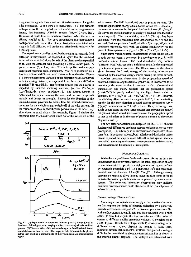
The experimental configuration for demonstrating magnetic field diffusion is very simple. As sketched in Figure 1 la, the insulated tether wire is stretched along the axis of the plasma column parallel to Bo with the chamber wall providing a coaxial return path. A pulsed current (Ia•. = 1 A, • = 20 gs) is applied and the only significant magnetic field component, B,(r,t), is measured as a function of time at different radial distances from the wire. Figure 11 b shows that the time variation of the magnetic field slows down with increasing distance, as expected from the vector diffusion equation V2B =goCh•B/•t. The field penetration into the plasma is impeded by induced shielding currents, J(r,t)= V xB/go = (gor)'•O(rB,)/Or, shown in Figure 12. The current density is distributed like a shell around the wire, and, in time, it spreads radially and decays in strength. Except for the direction of the induced current, governed by Lenz's law, the induced currents are the same for the switch-on and switch-off of the wire current. In
the former case, they impede the field penetration; in the latter, they slow down its rapid decay. For example, Figure 13 depicts the magnetic field B,(r) at different times t after the switch-off of the
At
(b)
Plasma 1012cm -3, 2eV , B o= 10 0 0. SA ß
•r z•r o/o# =o, O/i).z =o
25 rn
Kt2O
I
I I ,
Ar n o =9xi0 rlcrr• $ kT e =l. 6 eV
r= 3.4 crn
6.?
I0
I I I • I i I , I I
0 10 20 30 40 TIME t ( psec )
Fig. 11. (a) Experimental arrangement to investigate the interaction of an insulated, field-aligned wire carrying a pulsed current I(t) with the ambient plasma. (b) Time variation of the azimuthal magnetic fieldB,(t) at different radial distances r from the wire. The magnetic field diffuses into the plasma rather than exciting a normal mode of the system such as a magnetosonic wave.
wire current. The field is produced only by plasma currents. The stored magnetic field energy which, before switch-off, is essentially the same as in vacuum is dissipated by Ohmic losses, E. J = od 2. No waves are excited and thus no energy is fed back into the tether circuit (Iw = 0). The conductivity, c•, = 2.5 (f• cm) -•, has been calculated from the measured field dependence B,(r,t) and the vector diffusion equation, r -• •(r •B d•r )/Or - B,/r 2 = goC•B,/•t, and compares reasonably well with the Spitzer conductivity for the present plasma parameters (%p = 3.9 (f• cm) -• at kTe = 0.4 eV).
Since a time-varying current in a stationary wire (l II Bo) is subject to eddy current losses, a dc current in a moving wire (v _1_ Bo) will encounter similar losses. The field distribution may form a "diffusion wing" with upstream and downstream fields compressed by antiparallel plasma currents. The Ohmic losses in the plasma either decrease the kinetic energy of the moving tether or are provided by the electrical energy source driving the tether current.
Another important observation is the propagation speed of switched currents along the field-aligned wire. It is observed to be essentially the same as that in vacuum, v _< c. Conventional transmission line theory predicts that the propagation speed (v o• (LC) m) is greatly reduced by the high plasma dielectric constant, œ•_ = 1 - (l)p2/((l) 2 --•"•e 2) • O,)p2/•e 2, to V = C/100. However, the shielding effect prevents the magnetic field B, from penetrating rapidly for the short duration of axial current propagation (At = (t/goC•,) m = 5 mm for t = (2.5 m)/c = 8 ns). Thus, the energy flow E x H occurs along the wire surface rather than through the bulk of the plasma, which would have slowed down the propagation speed to that of whistlers as in the case of plasma currents to electrodes (Figures 2 and 3).
The two tether orientations investigated (l II Bo, l _1_ Bo) showed fundamental differences in plasma response (diffusion versus wave propagation). For arbitrary wire orientation or complicated struc- tures (e.g., large space stations), both radiative and dissipative losses can be expec[ed but may be more difficult to distinguish than in a controlled laboratory environment where geometry, end electrodes, and insulation can be separately investigated.
NONLINEAR CURRENTS
While the study of linear fields and currents forms the basis for understanding electrodynamic tethers, the actual application of long tethers is intended to operate in a highly nonlinear regime, defined by electrode potentials e•)/kTe >> 1 (typically 10 4) and maximum possible current densities J >_ ne(kTe/2nme)m. Although strong currents are known to drive various instabilities, it is still difficult to make theoretical predictions for a complicated dynamic current system. The following laboratory observations may indicate nonlinear processes which could also occur at the contact points of tethers in space.
Current-Voltage Characteristics
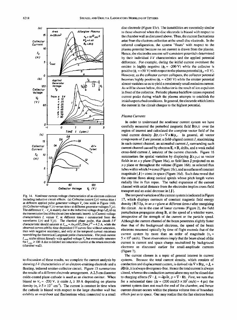
Assuming an unlimited current supply at the negative electrode, we first explore the limits of electron collection by a positively biased electrode consisting of a 2 cm diameter plane tantalum disc with surface normal along B o and one side insulated with a mica sheet. Figure 14a depicts the time waveforms of the collected current at different applied generator voltages Vg switched on at t = 0. Figure 14b lists the voltage levels Vg corresponding to the different traces a-i, and displays the voltage Vc (solid lines) measured directly at the collector. Collector and generator voltages differ by the potential drop along the transmission line as shown in the inserted circuit diagram. The voltages are referenced with

STENZEL AND URRUTIA: LABORATORY MODELING OF TETHERS 6217
B
Current
Density
•z 5- (mA/cm 2 )
4-
$-
2-
1-
0 0
I I I I
t = 2.5 I./Sec Electric Field
2
1 i] (rB#) = •tEz 2.5 (1• ½rn)-I
•0
• • • 200 12 16 RADIUS r ( cm )
Fig. 12. Radial profile of the field-aligned induced plasma currents J = V x B,/go, which impede the rapid penetration of magnetic fields into the plasma. With time t after switch-on/switch-off, the coaxial current shell (see inserted schematic) increases in radius, broadens in width, and decays in amplitude. The induced electric field has the same distribution as the current density and is obtained from Ohm's law, • = o,E:, with the conductivity % determined from the vector diffusion equation V2Bo = goO,3Bo/3t.
ß
/ 4 •5 -
0 4 8 12 16 20 RADIUS r (cm)
Fig. ] 3. Magnetic field B,(r) at different times t after switch-off of the wire cu•ent. The initially stored magnetic field energy is entirely dissipated in the plasma by Joule heating. A dc cu•ent-c•ying wire moving at a velocity Vy ß Bo would induce shielding cu•ents antip•allel to I•, which continu- ously dissipate energy of the prim• cu•cnt circuit.
respect to the chamber wall which forms the large negative ion collecting electrode (subsequently replaced by an electron beam source). While at small applied voltages (Vx _< V/•t = 5V) current
and voltages appear to remain constant after switch-on, both waveforms become highly time-dependent for currents of the order of the Langmuir saturation current I e =Anee(kre/2•me) ]/2 = 4.2 A (collector areaA -- 0.78 cm 2, n e = 10 ]2 cm -3, kTe -- 4 eV). For short durations (At -- 1 gs), the current far exceeds the Langmuir limit, subsequently collapses, and fluctuates around ]e' The large time- varying current generates a significant inductive voltage Ldlc/dt along the axial wire between generator and electrode (L -- 3 gH). During the current rise, the collector voltage Vc = Vg-Ldlc/dt is reduced while the opposite occurs during the current drop. In Figure 14c the current voltage characteristics for the collector I•. versus V•. are constructed at different times At after switch-on. These curves
evolve in time from an initial straight line during the current rise to characteristics with negative differential resistance during the current drop, to curves which appear like classical plane Langmuir probe characteristics [Chen, 1965], although they are not invariant in time. When the current is observed on a longer time scale (as shown in Figure 15), one finds repeated current spikes. These are not transient responses to the large initial current overshoot but also occur after a slow turn-on of the voltage which avoids the first overshoot [see Urrutia Pdez, 1987]. For repeated afterglows, the multiple current peaks fluctuate in timing and amplitude such that ensemble-averaged current traces appear much smoother than the single-event data of Figure 15. The fluctuations may exhibit transition to chaos. Such study is under way, but is outside the scope of this report.
The observations raise two major questions, (1) how is it possible to collect current far in excess of the Langmuir limit, and (2) how do the repeated current fluctuations arise? In order to clarify these points we have performed detailed in situ measurements of plasma parameters and current flows to be presented below. However, prior
6218 STENZEL AND URRUTIA: LABORATORY MODELING OF TETHERS
Current
Area • Afterglow Plasma 15 A=O. Scm 2 . / A ne =' 'Ol2 cm '3
Current
10
(b) 0 Applied .• . . Generator I
Voltage
Vc T•ce a 5 V
(V) 60 c 20 i I I d 25 I • •5
g 55
- o
TIME t (Nsec) (c)
•5
Collector Current
lc lo
5
0
08
0.6 Q4
$ec
O2
0 60 120
Collector Voltage V c (V)
Fig. 14. Nonlinear current-voltage characteristics of an electron collector including inductive circuit effects. (a) Collector current I•(t) versus time t at different applied pulse generator voltages V• (see scale in Figure 14b). (b) Collector voltage Vt(O versus time t at different generator voltages V•(O. The difference V• - V• is mainly due to the inductive voltage drop LdlJdt on the transmission line of the circuit (see schematic insert). (c) Current-voltage characteristics It versus V• at different times t constructed from the waveforms l•(t) and V/t). The classical plane probe, thin sheath I-V characteristic should saturate at Ie,sa , = Anee(kTJ2rCme) m -- 4.2 A, while the observed curves exhibit time-dependent I-V curves first without saturation, then with negative resistance, and only at the temporal current minimum resembling the theoretical Langmuir probe characteristic. The peak current L,mo• scales almost linearly with applied voltage V.•, but eventually saturates for I t .... > 100 A due to littilted ion saturation current at the return electrode (chamber wall).
to discussion of these results, we complete the current analysis by showing I-V characteristics of an electron-emitting electrode and a floating, tethered emitter-collector circuit. Figure 15 summarizes the results of a different electrode arrangement. A 2.5 cm diameter oxide-coated plane cathode is used as an electron emitter. When biased to Vb-- -200 V, it emits lb-> 10 A depending on plasma density (n e _> 5 X 10 TM cm-3). The current is constant in time when the cathode is biased with respect to the large chamber wall but exhibits an overshoot and fluctuations when connected to a small
disc electrode (Figure 15c). The instabilities are essentially similar to those observed when the disc electrode is biased with respect to the chamber wall as discussed above. Thus, the current fluctuations arise from the electron collection at the small disc electrode. In the
tethered configuration, the system "floats" with respect to the plasma potential because no net current is drawn from the plasma. Hence, the electrodes assume self-consistent potentials determined by their individual I-V characteristics and the applied potential difference. For example, during the initial current overshoot the emitter is highly negative (q•e = -200 V) while the collector is positive (q• = +50 V) with respect to the plasma potential (½pl =0 V). However, as the collector current collapses, the collector potential becomes highly positive (q• = +280 V) while the emitter potential almost vanishes so as to yield a consistently small emission current. As will be shown below, this behavior is the result of ion expulsion in front of the collector. Periodic plasma backflow causes repeated current peaks during which the plasma attempts to establish the initial unperturbed conditions. In general, the electrode which limits the current in the circuit charges to the highest potential.
Plasma Currents
In order to understand the nonlinear current system we have carefully measured the perturbed magnetic field B(r,t) over the region of interest and calculated the complete vector field of the total current density J(r,t)= V xB/go. In general, all vector components of J are present: a field-aligned current Jz maximizing in each current channel, an azimuthal current J, surrounding each current channel caused by electron E,. x Bo drifts, and a weak radial cross-field current Jr into/out of the current channels. Figure 16 summarizes the spatial variation by displaying J(x,y,z) as vector fields in an x-y plane (Figure 16a), as field lines J projected on an x-y plane or throughout the volume (Figure 16b), as selected flux tubes within which I = const (Figure 16c), and as surfaces of constant magnitude [ J I = const in space (Figure 16d). Such data reveal that the current flows along conical spirals whose pitch length varies radially like in flux ropes. The radial expansion of the current channel with axial distance from the electrodes implies cross-field transport and an axial decrease in I J 1.
The temporal variation of the current system is indicated in Figure 17, which displays contours of constant magnetic field energy density I B 12/2go in an x-z plane at different times t after energizing the circuit. As in the case of linear currents (Figure 2), the field perturbation propagates along Bo at the speed of a whistler wave, irrespective of the strength of the current or the particle speed. Although the current channel of the beam penetrates slightly faster than that of the background electrons, the speed of the beam electrons measured optically by time of flight exceeds that of the current system by more than an order of magnitude (vb = 5 x 10 s cm/s). These observations imply that the beam ahead of the current is current and space charge neutralized by background electrons as discussed earlier for small-amplitude currents (Figure 7).
The current closure is a topic of general interest in current systems. Because the total current density, which consists of conduction and displacement current, is derived via V x B/go = Jc + OD/Ot, it is always divergence-free. Hence the total current is always closed, whereas the conduction current alone may not be closed due to charging effects (V ß J• =-c)p/Ot, p = V '.D). First, we note that for a substantial time (At = (200 cm)/(5 x 107 cm/s)= 4 Its) the current system does not reach the end of the chamber, and hen.ce current closure occurs within the plasma volume free of boundary effects just as in space. One may realize that the fast electron beam

$TENZEL AND URRUTIA: LABORATORY MODELING OF TETHERS 6219
(aJ
End Anode
(b)
Current
(A)
Potential
200
100
•pl 0
-100
-200
•plasma "0
Source-free Maxwellian
Afterglow Plasma (lm 0 x2.Sm)
Collector
(c)
1o
5
(A)
0
10
•collector
Emitter
Time t (laser) ---- 10 20 30
Emitter
Current
_ to large anode
r
i i i
0 5 10 15 Time t (laser)
Fig. 15. Characteristics of a current system established with two floating electrodes emitting and collecting electrons on different flux tubes. (a) Schematic set up of electrodes (radius r = 1 cm, spacing d = 8 cm 3_ Bo (30 G) and major diagnostics to measure currents in the plasma. (b) Emitted electron current le(t) exhibits disruptions and fluctuations when connected to the electron-collecting disc but remains constant when connected to the chamber end wall. The unstable currents are created by plasma modifications near the collector, not the emitter. (c) Charging of the "floating" electrodes in an unstable current system. During the initial current "overshoot" the collector is slightly above plasma potential while the emitter is charged highly negative (= -200V), injecting a fast electron beam. Upon current disruption the collector charges to high positive potentials (+200V) while the emitter is close to the plasma potential. Subsequent current peaks repeat the sequence. In general, the electrode which limits the current flow develops the highest charge.
rapidly reaches the chamber wall (At -- (200 cm)/(5 x 108 cm/s)= 0.4 gs) but it has no effect on the internal current system because it carries no net current. The net particle flux at the floating chamber wall must remain balanced (lb + le +li = 0); thus the plasma electron flux (le) decreases, and the ion flux (Ii) slightly increases when the beam (lb) is absorbed at the wall. This is accomplished by a self-consistent plasma potential increase (Aq) <_ kTe/e) with respect to the wall. Because of the relatively slow speed of the front, the wall position (z = 200 cm) has no effect on the current closure or disruptive instabilities (the front is at z -- 50 cm when the instabil- ities start at t = 2 gs).
We return to the problem of current collection and closure and first show that the observations are inconsistent with classical dc
probe theories assuming random particle motions and electric fields confined to sheaths. For example, at a collision rate Ve, • 3 MHz and electron Larmor radius FLe -- 1.5 mm (kTe = 1.5 eV, Bo = 30 G),
electrons can randomly cross the magnetic field in At -- 1.5 gs only over distances Ar=(number of collisions)re(step length)= (Vet•)l/2FLe, thus the maximum number of electrons which can be collected by an electrode of radius r would be those in a flux tube ofradius r + Ar and length 1, N = n(r +/•r)21ne = 5.3 x 10¹³ particles (r = 1 cm, 1 = 50 cm, n e = 2 x 10 • cm-3). The number actually collected, N = Q/e = II/edt -- (10 A)(1.5 gs/e) -- 9 x 10 •3 particles, exceeds those classically available, which would lead to incon- ceivable space charge problems (Eñ = 2.4 x 10⁵ V/cm). Thus, a more realistic picture is that the collected electrons must come from a large plasma volume. To do so, they must be accelerated across and along Bo by internal electric fields. In addition, the ions should also contribute to the cross-field currents.
The observed current closure by cross-field currents is demon- strated in Figure 18. Two fictitious rectangular boxes define control surfaces which enclose the current channels of the electron emitter

6220 $TENZEL AND URRUTIA: LABORATORY MODELING OF TETHERS
(a) _
,t.
. , . r I • , , , , . . I ' ' ' (cm) O . ß ß ) • , .... • t ' ' '
=,6 I -8 0
x (cm) It A crrP-
3 - Vec t ors
,.._ .. ß , s . /.• .... •,,,7/ ,,,,•\ "•
' ' %'' /l ' ' '
................
Collector Emitter
1 cn'2-
(b) Fie I d tines
z=S crn t = 1.75 psec
Y
_
-- x - k, --•..• t• ø z
50cm
(c) Current Tubes (d) /•/ = const. Surfaces f_3.d_a = const.
t = 1.75psec
z 50cm
3= O.• A/cm 2 t = 1.25 psec
ß x
50cm
Fig. 16. Spatial characteristics of the current density J = V x H in the plasma with immersed electrodes at x = +4 cm, y = z = 0. (a) Vector field of perpendicular (Jx, Jy ) and parallel (J,,) current density in an x-y plane at a fixed time t after energizing the current system (100 V, 10 A). The transverse currents are both due to electron E r x Bo drifts, caused by space charge fields, and electron diamagnetic drifts Vp x Bo/(neBo 2) associated with heating. The field-aligned currents (normal to x-y plane, but plotted in +y direction for purpose of display) are due to electron injection and collection. (b) Field lines of the current density vector J(x,y,z) in an x-y plane (left) and in x-y-z space (right). The lines are nested helices of varying pitch lengths (pitch • --> oo on axis, lz -• 0 at boundary of flux tubes). (c) Two characteristic current "tubes" whose axes follow the J line. The cross sections conserve the current I = J. A. With distance from the electrodes the spiral radius and tube cross section expand due to a decreasing current density. Note that particle orbits differ from current lines. (d) Surfaces of constant current density I J I = const at a fixed time in space. Such surfaces bound regions of higher current density but do not imply lack of current closure since currents can cross the surfaces.
and collector (Figure 18a). The total current I =IAJ-da is integrated for each surface A and displayed versus time t in Figure 18b. One can see that the parallel current near the electrodes I,,z = 5cm is almost entirely accounted for by the perpendicular current I_• flowing through the four side surfaces of each box, and the field-aligned current at large distances I,,z=50cm is essentially neg- ligible for t < 2 gs. Although the radial current density Jr is small compared to JII and J,, the large transverse surface area allows the total current to flow almost exclusively across Bo. It is also interesting to note that the cross-field current does not exclusively flow through the plane between the two flux tubes but spreads radially in all directions. Thus, the Current closure does not occur
,
along the shortest path, as expected from dc concepts, but along two
diverging overlapping whistler waves. Wave and space charge electric fields aided by plasma turbulence are thought to provide for the strong cross-field currents.
Unfortunately, the evolution of the strong currents cannot be followed for longer times, since, as noted above, another overriding effect takes place, i.e., an instability at the collecting electrode which disrupts the continuation of large current flows. This process is analyzed•next.
Plasma Modifications
The current overshoot upon switch-on of a positive voltage step to a Langmuir probe was observed some time ago [Bills et al., 1962]

$TENZEL AND URRUTIA: LABORATORY MODELING OF TETHERS 6221
y
(crn )
'11 i iii i i i i i i i i111 ii i i i i i i I i i 1 111111 ii i Iiiii i i i i i i _
' t = 0.75 #sec B2/2Po = const. i Emitter
-" s o 8 c rn /s e c \
- \ .
\
• Collector
'1 i 11111 I i i' I i i i i I i i iiii i ii i i i i i i i i i I i i i I i i i i I i i i I i
. 1.0 •
\
• •7=5xlO?crn/sec
\
l I I Illl 11 I III I III I III II III i I•1 I i III I III III ! III I I Ii-- 1.25
\ _Bo-'-----
\ ß
\
0 10 20 30 •0 50
z (crn)
Fig. 17. Temporal properties of the current system, showing contours of constant energy density (•B 2/2•o = 1.2 x 10 -9 J/cm 3 per contour) of the perturbed magnetic field in the x-z plane at different times t after switch-on of the electrode potential V. EV&fi fø3 strong currents (I = 10 A, •/Bo-- 3%) the magnetic perturbation, i.e., net current, is transported by a collective 'Plasma møde (a whistler wave) and not at the speed of the beam electrons (v h -- 5 x 10 s cm/s) which is measured optically. The b•am front, Which produces no measurable magnetic field, must be both current neutralized (J_ = 0 since B, = By = 0) and space charge neutralized (p = 0, E = 0, J, = 0 since B. = 0) by background electrons.
and plausibly explained by the expulsion of excess ions from the sheath which changes from ion-rich to electron-rich [Chen, 1965]. The present observations extend and significantly modify this model as demonstrated by Figure 19, which displays the collected current versus time for the same step voltage (V, = + 100 V) to three plane electrodes of very different areas (3 mm 2, 3 cm 2, 20 cm2). Since the sheath thickness (10•o --0.4 mm) is small compared to
the probe dimensions, the duration of the overshoot (At _> 1/f•i -- O. 1 Its) should not depend on probe size if only the ions in the sheath would be expelled. However, the data clearly show that both the duration of the overshoot and the repetition time of subsequent overshoots increase with collector size (t o• r•), suggesting that the ion perturbation and associated electric fields are not confined to the sheath but to a volume determined by the collector size.

6222 STENZEL AND URRUTIA: LABORATORY MODELING OF TETHERS
55
(b) i i i
Emitter I3+I4+I5+I 6 I
0 12 - =0
-
•6 I I I
(C) Collector• iT - .
A ) • \ 170 o 2•a 0
0 I 2 3
Time t (psec)
Fig. 1 8. Cu•ent consedation and closure analysis. (a) A fictitious box Js drawn around each cu•ent channel, and the net cu•ent I = •J- da through each control surface is calculated. The field-aligned cu•ents are I I, I: for the electron emitter •d ll0, Ill for the electron collector box. The cross-field cu•ents are 13,14,15,16 for the beam and 16, I•, I•, 19 for the collector. (b) Cu•ents I, through different surfaces for each box versus time t prior to dis•ption. Cu•ent consedation •,=161, = 0, -16 +X,=•l if, = 0 is satisfied. For t • 2 Hs, the parallel cu•ents near the electrodes, Ii, ll0, are mainly accounted for by pe•endicul• cu•ents I I = •,=361,, I•0 = -I 6 + •,=•91, •d not by distant field-aligned cu•ents I: << Ii, Ill << I•0. The pe•endicul• cu•ents not only flow through the joint interface between the two cu•ent channels •,=•91,, expected from dc concepts to be the path of least resistance, but flow in all directions across Bo, consistent with a diverging wave cu•ent.
Using the smallest (r•. = 1 mm) and least perturbing electrode at low voltages (Vbi,s < V,/•sm•) as a diagnostic Langmuir probe by the procedure outlined earlier, we have measured the plasma parame- ters in space and time around a large collector (2 cm diameter) exhibiting current overshoots. Figure 20 shows the plasma density
(0.2A/div)
Coil ec tot Current
lc
(20 A/d/v)
Time t (10 Hsec/div )
(0.2A/div)
(20 A/div)
EXPANDED
I I I I I I I I I I I
"•n •'•
/ " Inductance-limited current rise
l=•-t -- IOO V t = 33 A/.sec.t I I I I i
Time t (0.5 psec/div )
Fig. 19. Collector currents l(t) for three electrodes of different sizes biased by the same step voltage V(t) = + 100 V (Atp,/se > tr, se = 50 ns). The upper three traces show the long-time behavior, the lower traces show the first overshoot on an expanded time scale. The results indicate that both the width and the repetition time of current overshoots increase with collector size, and hence cannot be explained by ion expulsions from a sheath but from a volume determined by the size of the collector. The current rise time is influenced by global circuit properties, e.g., the inductance of the feeding transmission line (L = 3 gH).
rt e versus radius r and time t after switch-on of the cotlector voltage (V, = + 100 V) at zSz = 1 cm in front of the collector. The initially uniform density profile develops a deep density depletion (Sn/n -- 80%) inside the current channel. Plasma is expelled to the sides with supersonic velocities (ZkrlAt-- 2 cm/2 Its = 10 6 cm/s > c s = (kre/m,) 1/2= 2 x 105 cm/s), partly diffuses back, and is quasi- periodically re-expelled (at t = 5 and 10 Its, on the average). Due to necessary ensemble averaging, the repeated density perturbations are reduced in size because their timing fluctuates from shot to shot. Axially, the density depression is deepest in front of the electrode (Sn/n= 100%) and gradually decreases with distance along Bo (fin/n = 50% at z = 10 cm), implying that the unmagnetized ions (rL, > 20 cm) are expelled mainly across Bo out of the positively charged current channel. Ions are expelled but not lost to the wall, while electrons are attracted into the current channel and absorbed
at the collector. In spite of the different particle flows, the space charge neutrality is preserved to a high degree ((he- hi)In =V' Dine = 10-4); thus the expulsion of ions causes a proportionate loss of collected electrons, i.e., a current drop. After

STENZEL AND URRUTIA: LABORATORY MODELING OF TETHERS 6223
4 x 7011
DENSITY
(cm -3)
Collector
,it Z= ? c rn
TIME t
I ,o
20 0 -5.5 RADIAL POSITION r (crn )
5.5
Fig. 20. Radial density profile he(r) versus time t after switch-on of a large collector voltage (V• = +100 V). The density is obtained from complete Langmuir probe traces taken with a small (r -- 1 mm) probe scanned at z = 1 cm in front of the 2 cm diameter plane collector. The initially uniform density profile develops a deep depletion coincident with the disruption of the collector current. Plasma expelled to the sides of the Current channel flows partly back, which allows repeated smaller current overshoots.
current collapse, the plasma pressure causes a reversal of the ion motion until the next expulsion takes place. The width of the overshoot is determined by the collector radius r• and ion expulsion velocity (2eVJmt) u2 while the repetition time depends on rc/(kre/mi) w2 [Urrutia P6ez, 1987]. Such dynamical effects are best observed in an afterglow plasma because in an active discharge they would be obscured by the continuous plasma production.
Thus, in contrast to the conventional picture, the current over- shoot is not due to an excess ion density near the collector which is removed to result in a uniform plasma, but to large currents flowing in an initially uniform plasma that is subsequently perturbed. This implies that the low time-averaged dc current cannot be explained by the conventional Langmuir probe theory which assumes an unperturbed plasma beyond the sheath. Likewise, the high initial current can only arise due to the penetration of electric fields beyond the sheath into the plasma volume. Such fields are measured and displayed in Figure 21. The particles experience predominantly the field E =-Vqb caused by plasma potential gradients, while pressure gradients (Vp/he) causing diamagnetic electron drifts are negligible at early times (t < 2 ps). Near the collector (z -- r• -- 1 cm), strong parallel fields (Ej--6 V/cm) are observed in addition to perpen- dicular fields (E•_ -- 4 V/cm) which maximize near the edge of the current channel (r -- 2 cm) up to large axial distances (z -- 30 cm). These fields are responsible for accelerating electrons to velocities far in excess of the initial thermal velocity, and to collect them over a long cylindrical surface of area (2rcrz -- 380 cm 2) much larger than that presented by the collector's sheath (•r• 2 = 3.14 cm2). The ion expulsion also adds to the observed cross-field current (Ii = 2rcrzn, e(vi} = 2.4 A, (v,} = 2 x 105 cm/s). The large current density near the collector (I/•r• 2 = nevd -- 3 A/cm2; n = 2 x 10 • cm -3, vd-- 108 cm/s) is associated with a high effective electron temper-
_
_
t : ß ß ' t I I t , ß ....
5 10 z (cm)
Fig. 21. Vector map of the electric field in an x-z plane at a fixed time during large current flows and beginning density depletions near the electrode. The electric field E = -Vqb is obtained from determining the plasma potential qb at each point from complete Langmuir probe traces. The classical Debye sheath thickness is s -- 10•,D -- 0.4 mm, the classical Ohmic parallel field is E, = J,/(•,-- 0.024 V/cm, indicating that the observed large fields (E, <_ 6 V/cm) outside the sheath are anomalously large. The perpendicular space charge electric field Eñ <_ 4 V/cm gives rise to electron Hall currents (see Figure 17) and expulsion of the unmagnetized ions from the original current channel.
ature (me(¾e2}/2 = kTe• -> 4 eV). The parallel electric field cannot be explained by classical collisions (c•, = J,/E, = 3 A/cm/(3 V/cm) 1 (f• cm) -• at t-- 1 ps; tJsp = 153Te3/2/lnA = 122 [Spitzer, 1962]). Both the parallel drift and the E, x Bo electron drift (va=EJBo-- 1.3 x 107cm/s) far exceed the sound speed (Cs = (kTe/m,) 1/2 -- 2 x 105 cm/s) such that ion acoustic waves are destabilized. Evidence for plasma turbulence is shown below.
As the overshoot current collapses, the electrode potential, and hence parallel electric fields, is greatly enhanced by the inductive voltage LdI•/dt (see Figure 14b). When the potential drop in the plasma exceeds the ionization potential (eVl -- 15.4 V in Ar), and an adequate number of neutrals is present (no >- 2.5 x 10 •3 cm -3, Po >- 7 x 10 -4 Torr), we observe the ionization of the neutrals by electron impact. Figure 22 shows current waveforms I(t) at gas pressures below (Po > 4 x 10 -4 Torr, Figure 22a) and above (Po > 7 x 10 -4 Torr, Figure 22b) onset ofionization for an applied collector voltage V• = + 100 V. Ionization phenomena are usually accompanied by excitation of light, also displayed in Figure 22, which is easily detected since the surrounding afterglow plasma is dark. The ionization starts after the first current overshoot and produces a growing plasma cloud ("contactor") in front of the collector, which has independently been mapped with probes [Urrutia P6ez, 1987]. As long as the ion production by ionization exceeds the rate of ion expulsion by the electric field, the large electron current to the collector can be maintained. However, at: t > 25 ps both ionization and current decay in spite of a constant collector voltage. The finite duration of ionization is explained by a decrease in neutral density (n, • 3 x 10 •3 cm -3) at the contactor since the fast ion outflow (N, = IAt/e -- 5 x 10 TM ions) exceeds the slow neutral inflow (N, 3 x 10 TM atoms for a 10-cm 3 contactor volume). It is interesting to note that with a longer repetition time (t • 100 ps) determined by the neutral inflow, the ionization proces. s repeats like a relaxation oscillation.
The counterstreaming electron and ion saturation currents near the collector biased at V• >> kTJe provide the necessary conditions
6224 $TENZEL AND URRUTIA: LABORATORY MODELING OF TETHERS
Current
(10 A/div)
,,
Current Ar • p =gxlO'4 rr :: ,oo v
I 1 ' •Curre•t••
..... ............. , . .
Light Emission
(Arb. units)
7irne t ( 51•sec/div )
Fig. 22. Collector current and light emission from the plasma in front of the collector versus time at low neutral pressures (top traces) and high pressures (bottom traces) at the same collector voltage (V, = +100 V). The energization of electrons by electric fields in the current channel gives rise to ionization at high neutral presssums, accompanied by light emission. Replenishing the expelled ions by ionization allows sustained large current collection by the self-generated plasma "contactor." When the ion outflow exceeds the neutral inflow (t _> 30 Ms) the ionization and current collection disrupt and go over into a slow relaxation mode (t,,,p = 100 Ms).
for the formation of a potential double layer [Block, 1978]. Anodic double layers have been observed in various laboratory plasmas [Torvdn and Andersson, 1979; Alpart et al., 1986] and have been investigated in the present device in connection with current sheet disruptions during magnetic reconnection [Stenzel et al., 1983]. In the presence of ionization, the double-layer potential drop is of the order of the ionization potential.
Microinstabilities
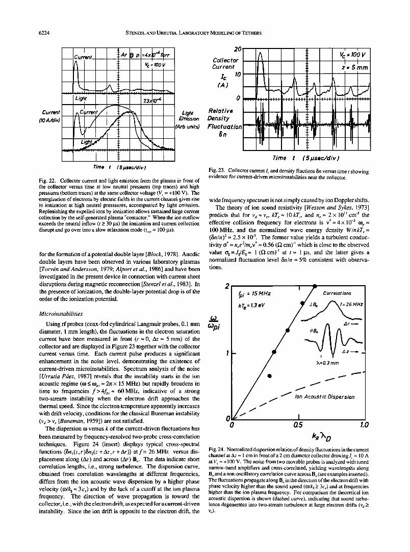
Using rf probes (coax-fed cylindrical Langmuir probes, 0.1 mm diameter, 1 mm length), the fluctuations in the electron saturation current have been measured in front (r = 0, z•z = 5 mm) of the collector and are displayed in Figure 23 together with the collector current versus time. Each current pulse produces a significant enhancement in the noise level, demonstrating the existence of current-driven microinstabilities. Spectrum analysis of the noise [Urrutia Pdez, 1987] reveals that the instability starts in the ion acoustic regime (co _< co,, = 2•r x 15 MHz) but rapidly broadens in time to frequencies f> 4f,, = 60 MHz, indicative of a strong two-stream instability when the electron drift approaches the thermal speed. Since the electron temperature apparently increases with drift velocity, conditions for the classical Buneman instability (vd > ve [Buneman, 1959]) are not satisfied.
The dispersion co versus k of the current-driven fluctuations has been measured by frequency-resolved two-probe cross-correlation techniques. Figure 24 (insert) displays typical cross-spectral functions (6n](z,r)6n2(z + z•z,r + •)) at f= 26 MHz versus dis- placement along (z•z) and across (•) Bo. The data indicate short correlation lengths, i.e., strong turbulence. The dispersion curve, obtained from correlation wavelengths at different frequencies, differs from the ion acoustic wave dispersion by a higher phase velocity (co/k, = 3cs) and by the lack of a cutoff at the ion plasma frequency. The direction of wave propagation is toward the collector, i.e., with the electron drift, as expected for a current-driven instability. Since the ion drift is opposite to the electron drift, the
20
Collector Current
o
Relative
Density Fluctuation
$n
Time t ( 51asec/div )
Fig. 23. Collector current I, and density fluctions fin versus time t showing evidence for current-driven microinstabilities near the collector.
wide frequency spectrum is not simply caused by ion Doppler shifts. The theory of ion sound resistivity [Wesson and Sykes, 1973]
predicts that for va = ve, kT• = 10 kT,, and n• = 2 x l0 II cm -3 the effective collision frequency for electrons is v*= 4 x 10 -3 cop = 100 MHz, and the normalized wave energy density W/nkT• = (6n/n)2= 2.5 x 10 -3. The former value yields a turbulent conduc- tivity o* = n•e2/rnev * = 0.56 (• cm) -] which is close to the observed value %1 =J,/E, = 1 (• cm) -] at t = 1 Ms, and the latter gives a normalized fluctuation level fin/n = 5% consistent with observa-
tions.
21 • i=15MHz I/ Correlations
'!- /' : v
0 / I 0 05 tO
k. '>,, o Fig. 24. Normalized dispersion relation of density fluctuations in the current channel at Az = 1 cm in front ofa 2 cm diameter collector drawing I, = 10 A at V, = + 100 V. The noise from two movable probes is analyzed with tuned narrow-band amplifiers and cross-correlated, yielding wavelengths along Bo and a non-oscillatory correlation curve across B o (see examples inserted). The fluctuations propagate along Bo in the direction of the electron drift with phase velocity higher than the sound speed (co/k, > 3Cs) and at frequencies higher than the ion plasma frequency. For comparison the theoretical ion acoustic dispersion is shown (dashed curve), indicating that sound turbu- lence degenerates into two-stream turbulence at large electron drifts (vd >

$TENZEL AND URRUTIA: LABORATORY MODELING OF TETHERS 6225
Thus, a possible scenario for the current overshoot is the growth ofcurrent-driven microinstabilities, generating parallel dc electric fields and increasing the cross-field transport, which allows the collection ofmore electrons, providing positive feedback for growth of turbulence, currents and fields. The growth saturates when the ions begin to move out of the current channel in response to space charge and resistive electric fields. The strongest turbulence is observed during the current collapse when inductive electric fields try to maintain the current density in spite of a decreasing particle density, implying a high drift velocity. Electrostatic fluctuations near the electron •plasma frequency (f= 2...4 GHz) are detected, and even electromagnetic radiation is detected remotely and iden- tified as harmonics of the sheath-plasma resonance driven unstable by electron transit time effects [$tenzel, 1988].
The microinstabilities excited by an electron beam have been investigated in related earlier experiments [Whelan and Stenzel, 1985]. The predominant modes are Langmuir waves (to •_ top) driven unstable by the cold beam-plasma instability [Briggs, 1964], and return-current-driven ion acoustic instabilities. The high- frequency instability develops strong Langmuir turbulence within a distance zSz = 10•o--10vb/fp-- 2 cm from the cathode, which scatters both beam and background electrons. Suprathermal elec- tron tails are formed and bulk electron heating occurs [Needelman and Stenzel, 1987]. The scattering of Langmuir waves (toe) Off ion acoustic waves (toi) produces weak electromagnetic waves (toem • toe--tot •-- top, kem= ke- ki • 0). None of these instabilities seriously impede the current flow. Since the current channel charges negatively, it attracts ions and prevents current disruptions by density depletions.
CONCLUSIONS
The present laboratory experiments have addressed several important issues of the physics of electrodynamic tethers: time dependence and motion of currents; the global current system including propagation, closure, electrodes, and transmission lines; nonlinear phenomena such as current disruptions by density depletion; anomalous electric fields leading to unlimited current collection; and anode contactor generation by self-ionization. It is interesting to speculate on the implications of these findings on the behavior of tethers in space.
In the linear regime the first finding that currents from/to small electrodes advance at whistler wave speeds rather than Alfv•n speeds is directly applicable to space experiments. For typical shuttle speeds (Vs-< 8 km/s) and effective collector sizes of D-- 1.6 m diameter, the duration of the current pulse drawn on the collector flux tube is At = D/vs =0.2 ms = 1/5 kHz. This time is too short to excite Alfv6n waves •cCl = 30 Hz for O +) but appropriate to couple to low-frequency whistlers •/fe • 1/200). Since the whistler group velocity vg • 2c(•O.e/top2) 1/2• 4,500 km/s is almost three orders of magnitude higher than the spacecraft velocity, the angle of whistler wings will be entirely negligible (0 = 0). However, this does not imply that the current remains field aligned because the contactor, which is small compared to the typical whistler wave- length 0hi- Vph/f---- 3 km), radiates like a point source. The current spreads within the whistler ray cone (0--19ø), leading to overlapping of wings within a distance L > 30 km along Bo, and possibly defining the scale length for the effective current closure.
While the insulated tether wire does not give rise to dc plasma currents, it will induce ac current pulses on each flux tube. The tether should generate a comoving, wedge-like whistler radiation pattern along its entire length (l = 20 km). An observer on the ground may be able to detect a whistler tone burst as the tether passes
by, while a free-flying diagnostic sub-satellite may be able to map the dc magnetic field perturbations with a magnetometer.
Electron beams injected along B o may be distinguished from the current system by the small particle spread across B o and the higher propagation speed (--40,000 km/s) which should leave the beam front current-neutralized. Modulating the electron beam in order to generate VLF magnetic fields with a large (L >> 30 km) "phantom" loop does not appear feasible with a current-neutralized beam. It is the whistler wing structure which represents effectively the magnetic source distribution for exciting VLF waves (to -- 0).
A long, field-aligned current-carrying wire moving rapidly across Bo is subject to magnetic shielding by induced field-aligned plasma currents. The diffusivity (goO) -• -- x•/t and the motion v = x/t determine the scale length x --(VgoO) -• _< 1 m for the field pene- tration. Hence, a long wire or a large wire loop may not be as effective a VLF radiator in plasmas as in free space.
The nonlinear phenomena are mainly related to microinstabilities and the ion dynamics near the positive electrode. In the absence of contactors, the ion expulsion by the large tether potentials (kV) far exceeds the ion ram energy (--4 eV for O+); hence current disrup- tions and fluctuations are likely to occur even for a moving passive collector. However, the collector can remain in continuous contact
with the ambient plasma and draw large dc currents by supplying the expelled ions from a plasma source. The contactor may consist of an independent plasma source (hollow cathode) or a neutral gas cloud ionized by ambient electrons accelerated to the ionization potential in a distributed or localized electric field (double layer). In dense contactor plasmas (top/qe >> 1) the collection of electrons across Bo is found to be much easier than expected on the basis of classical collisions (oñ • (JiiVei2/•-•e 2oc tle2re-3/2B-2). The present laboratory experiment does not, however, address the effects 'of relative motion of a gaseous contactor with respect to the ambient magnetoplasma which include drag, electrodynamics, plasma expansion, and instabilities.
Acknowledgments. The authors gratefully acknowledge stimulating discussions with B. Fried, G. Morales, D. Hastings and N. Singh. We also appreciate L.-Y. Chan's expert help in preparing the presented material. This material is based upon work supported by the National Science Foundation under awards PHY87-13829, and ATM 87-02793 and by the National Aeronautics and Space Administration under grant NAGW-1570.
The Editor thanks M.D. Grossi and R. L. Merlino for their assistance in
evaluating this paper.
REFERENCES
Alport, M. J., S. L. Cartier, and R. L. Merlino, Laboratory observations of ion cyclotron waves associated with a double layer in an inhomogeneous magnetic field, J. Geophys. Res., 91, 1599-1608, 1986.
Banks, P.M., P. R. Williamson, and K.-I. Oyama, Electrical behavior of a shuttle electrodynamic tether system (SETS), Planet. Space Sci., 29, 139-147, 1980.
Barnett, A., and S. Olbert, Radiation of plasma waves by a conducting body moving through a magnetized plasm•i, J. Geophys. Res., 91, 10,117-10,135, 1986.
Belcastro, V., P. Veltri, and M. Dobrowolny, Radiation from long con- ducting tethers moving in the near-Earth environment, Nuovo Cimento, 5, 537-560, 1982.
Bills, D. G., R. B. Holt, and B. T. McClure, Pulsed Probe Measurements, J. Appl. Phys.,33, 29-33, 1962.
Block, L. P., A double layer review, Astrophys. Space Sci., 55, 59, 1978. Briggs, R. J., Electron-Stream Interaction With Plasmas, MIT Press,
Cambridge, Mass., 1964. Buneman, O., Dissipation of currents in ionized media, Phys. Rev., 115,
503-517, 1959.
6226 $TENZEL AND URRUTIA: LABORATORY MODELING OF TETHERS
Chan, L. Y., and R. L. Stenzel, Propagation of an electron beam front into -magnetized plasmas, Bull. Am. Phys. Soc., 33, 1950, 1988.
Chen, F. F., Electric probes, in Plasma Diagnostic Techniques, edited by R. H. Hudd!e•t,--,- and S. L. Leonard, pp. 113-200, Academic, San Diego, Calif., 1965.
Colombo, G., E. M. Gaposchkin, M.D. Grossi, and G. C. Weiffenbach, Long-tethered satellites for the shuttle orbiter, in Technologie des Experiences Scientifiques Spatiales, pp. 307-315, Centre Nationale d'Etudes Spatiales, Paris, France, 1975.
Dobrowolny, M., Electrodynamics of long metallic tethers in the iono- spheric plasma, Radio Sci., 13,417-424, 1978.
Drell, S. D., H. M. Foley, and M. A. Ruderman, Drag and propulsion of large satellites in, the ionosphere: an Alfv6n propulsion engine in space, J. Geophys. Res., 70,3131-3145, 1965.
Fisch, N.J., and C. F. F. Kamey, Current generation with low-frequency waves, Phys. Fluids, 24, 27-39, 1981.
Goertz, C. K., Io's interaction with the plasma torus, J. Geophys. Res., 85, 2949-2965, 1980
Goldreich, P., and D. Lynden-Bell, Io, a Jovian unipolar inductor, Astrophys. J., 156, 59-78, 1969.
Griem, H. R., Plasma Spectroscopy, McGraw-Hill, New York, 1964. Grossi, M. D., and G. Colombo, Interactions of a tethered satellite system
with the ionosphere, in Proceedings of the University of Alabama/NASA Workshop on the Uses of a Tethered Satellite System, edited by S. T. Wu, pp. 176-181, University of Alabama, Huntsville, 1978.
Hastings, D. E., A. Barnett, and S. Olbert, Radiation from large space structures in low Earth orbit with induced ac currents, J. Geophys. Res., 93, 1945-1960, 1988.
Helliwell, R. A., Whistlers and Relatedlonospheric Phenomena, chapter 1, Stanford University Press, Stanford, Calif., 1965.
Jackson, J. D., Classical Electrodynamics, p. 299, John Wiley, New York, 1962.
Klozenberg, J.P., B. McNamara, and P. C. Thonemann, The dispersion and attenuation of helicon waves in a uniform cylindrical plasma, J. Fluid Mech., 21,545-563, 1965.
Langmuir, I., Scattering of electrons in electrons in ionized gases, Phys. Rev. A, 26, 585-613, 1926.
Martinez-Sanchez, M., and D. E. Hastings, A systems study of a 100 kW tether, J. Astronaut. Sci., 35, 75-96, 1987.
Morrison, P. J., W. B. Thompson, and P. R. Williamson, Current collection by a long wire in near-Earth orbit, IEEE Trans. Plasma Sci., PS-6, 435-441, 1978.
Myers, N. B., W. J. Raitt, B. E. Gilchrist, P.M. Banks, T. Newbert, P. R. Williamson, and S. Sasaki, A comparison of current-voltage relationships of collectors in the earth's ionosphere with and without electron beam emission, Geophys. Res. Letr, 16, 365-368, 1989.
Needelman, D. D., and R. L. Stenzel, Cross-field electron thermal con- ductivity in an electron-beam plasma system, Phys. Rev. Lett., 58, 1426-1429, 1987.
Obayashi, T., N. Kawashima, K. Kuriki, M. Nagatomo, K. Ninomiya, S. Sasaki, M. Yanagisawa, I. Kudo, M. Ejiri, W. T. Roberts, C. R. Chappell, D. L. Reasoner, J. L. Burch, W. L. Taylor, P.M. Banks, P. R. Williamson, and O.K. Garriott, Space experiments with particle accelerators, Science, 225, 195-196, 1984.
Rasmussen, C. E., P.M. Banks, and K. J. Harker, The excitation of plasma waves by a current source moving in a magnetized plasma: The MHD approximation, J. Geophys. Res., 90, 505-515, 1985.
Sheridan, T. E., and M. A. Hayes, Multichannel boxcar-averaged mea- surements of plasma parameters made using a digital storage scope, Rev. Sci. Instrum., 59, 1081-1084, 1988.
Shercliff, J. A., A Textbook of Magnetohydrodynamics, Pergamon, New York, 1965.
Spitzer, L., Jr., Physics of Fully Ionized Gases, p. 139, Wiley-Interscience, New York, 1962.
Stenzel, R. L., Antenna radiation pattern in the whistler wave regime measured in a large laboratory plasma, Radio Sci., 11, 1045-1056, 1976.
Stenzel, R. L., Instability of the sheath-plasma resonance, Phys. Rev. Lett., 60, 704-707, 1988.
Stenzel, R. L., High-frequency instability of the sheath-plasma resonance, Phys. Fluids B, 1, 2273-2282, 1989.
Stenzel, R. L., and W. F. Daley, Large, Indirectly heated, oxide-coated cathode for producing uniform plasmas, U.S. Patent 4,216,405, August 5, 1980.
Stenzel, R. L., and J. M. Urrutia, Laboratory model of a tethered balloon- electron beam current system, Geophys. Res. Lett., 13, 797-800, 1986.
Stenzel, R. L., and J. M. Urrutia, Whistler wings from moving electrodes in a magnetized laboratory plasma, Geophys. Res. Lett., 16, 361-364, 1989.
Stenzel, R. L., W. Gekelman, and N. Wild, Magnetic field line reconnection experiments, 5, Current disruptions and double layers, J. Geophys. Res., 88, 4793-4804, 1983.
Stenzel, R. L., W. Gekelman, and J. M. Urrutia, Lessons from laboratory experiments on reconnection, Adv. Space Res., 6, 135-147, 1986.
Torv6n, S., and D. Andersson, Observations of electric double layers in a magnetized plasma column, J. Phys. D; Appl. Phys., 12, 717-723, 1979.
Urrutia Pfiez, J. M., Experimental study of time-varying current flow between electrodes immersed in a laboratory magnetoplasma, Ph.D. dissertation, University of California, Los Angeles, 1987.
Urrutia, J. M.,and R. L. Stenzel, Anomalous currents to an electrode in a magnetoplasma, Phys. Rev. Lett., 57, 715-718, 1986.
Urrutia, J. M., and R. L. Stenzel, Transport of current by whistler waves, Phys. Rev. Lett., 62,272-275, 1985.
Wesson, J. A., and A. Sykes, theory of ion-sound resistivity, Phys. Rev. Lett., 31,449-452, 1973.
Whelan, D. A., and R. L. Stenzel, Electromagnetic radiation and nonlinear energy flow in an electron beam-plasma system, Phys. Fluids, 28, 958-970, 1985.
Wilbur, P. J., and T. Laupa, Plasma contactor design for electrodynamic tether applications, Adv. Space Res., 8, 221-224, 1988.
Williamson, P. R., P.M. Banks, and K. Oyama, The electrodynamic tether, in Proceedings of the University of Alabama/NASA Workshop on the Uses of a Tethered Satellite System, edited by S. T. Wu, pp. 163-175, University of Alabama, Huntsville, 1978.
Williamson, P. R., W. F. Denig, P.M. Banks, W. J. Raitt, N. Kawashima, K. Hirao, K. I. Oyama, and S. Sasaki, Measurement of vehicle potential using a mother-daughter tethered rocket, in Artificial Particle Beams in Space Plasma Studies, edited by B. Grandal, pp. 645-653, Plenum, New York, 1982.
Winckler, J., The application of artificial electron beams to magnetospheric research, Rev. Geophys., 18, 659-682, 1980.
Wong, K.-L., R. Horton, and M. Ono, Current generation by unidirectional lower hybrid waves in the ACT-1 toroidal device, Phys. Rev. Lett., 45, 117-120, 1980.
R. L. Stenzel and J. M. Urrutia, Department of Physics, UCLA, Los Angeles, CA 90024-1547.
(Received June 29, 1989; revised October 23, 1989;
accepted November 8, 1989.)