Embed Size (px)
Citation preview

Current
Faraday
Sheet Formation in a Conical Theta Pinch
Accelerator with Radio-frequency Assisted
Discharge
IEPC-2007-165
Presented at the 30 th International Electric Propulsion Conference, Florence, Italy
September I%20, 2007
Ashley K. Hallock* and Edgar Y. Choueiri_
Princeton lStiversity, Princeton, N J, 085_0, USA
Kurt A. Polzin$
NASA - Marshall @ace Flight Center, HuntsviUe, A L, 35812, Ub'A
The inductive formation of current sheets in a conical theta pinch FARAD (Faraday Ac-
celerator with Radio-frequency Assisted Discharge) thruster is investigated experimentally
with time-integrated photography. The goal is to help in understanding the mechanisms
and conditions controlling the strength and extent of the current sheet, which are two in-
dices important for FARAD as a propulsion concept. Theprofiles of these two indices alongthe inside walls of the conical acceleration coil are assumed to be related to the profiles of the
strength and extent of the luminosity pattern derived from photographs of the discharge.
The variations of these profiles as a function of uniform back-fill neutral pressure (with no
background magnetic field and all parameters held constant) provided the first clues on the
nature and qualitative dependencies of current sheet formation. It was found that there is
an optimal pressure for which both indices reach a maximum and that the rate of change
in these indices with pressure differs on either side of this optimal pressure. This allowedthe inference that current sheet formation follows a Townsend-like breakdown mechanism
modified by the existence of a finite pressure-dependent radio-frequency-generated electron
density background. The observation that the effective location of the luminosity pattern
favors the exit-half of the conical coil is explained as the result of the tendency of the
inductive discharge circuit to operate near its minimal self-inductance. Movement of the
peak in the luminousity pattern towards the upstream side of the cone with increasing
pressure is believed to result from the need of the circuit to compensate for the increase
in background plasma resistivity due to increasing pressure.
Nomenclature
d
'n c
/7 n
p*
lie-- n
= distance from tile cone inlet
= electron munber density
: neutral number density
= critical pressure
= half cone angle of inductive coil
= electron-neutral collision frequency
*Graduate Student, Mechanical and Aerospace Department, ahallock(_-princeton.edu.tChief Scientist EPPDyL, choueiriCt_t}rinccton.edu.
tPropulsion Research Engineer, Propulsion Research and Technology [email protected].
Propulsion Systems Dept.,
1
The 3{} ta International Electric Propulsion Conference, Florence, ltalg
Septcmbcr 17-20, 2007
https://ntrs.nasa.gov/search.jsp?R=20070037448 2018-06-18T13:39:40+00:00Z

Cone Outlet
I
I. Introduction
Electrode-less spacecraft propubion thrusters arc attractive devices due to their avoidance of lifetimelimiting electrode erosion and their ability to use electrode-illcompatible propellants (such as CO2 and H20).Pulsed inductive thrusters! are OllC type of electrode-less plasma propulsion devices. Their operatioll consistsof a high frequency current pulse through all inductive coil that induces a time-changing magnetic field and,in accordance with Faraday's Law of Induction, all electric field. If propellant is within a certain distance ofthe coil, this electric field will break down neutral gas and the changing magnetic field will induce a sheetcarrying current opposing that in the coil. The interaction of the current density in the sheet with theinduced magnetic field produces a Lorentz body force density that will act to expel the current sheet awayfrom the coil, entrainillg propellant and producing thrust.
Because the coupling between the propellallt and the inductive coil affects the efficiency of the thruster,it benefits the design to provide propellant to the inductor that has already been ionized through someexternal means. 2 A pulsed inductive propulsion device, called the Faraday Accelerator with Radio-frequencyAssisted Discharge (FARAD), was first introduced by Choueiri and Polzin3 who carried out proof-of-conceptexperiments, derived design criteria,4 and described some potential advantages over a previous concept, thePulsed Inductive Thruster (PIT).!,5,6 Among these potential advantages is FARAD's ability to form currentsheets at much lower capacitor voltages and energies than PIT (1.5kV, 44J versus 30kV, 4kJ) through theuse of a RF-generated preionization. This advantage incurs the added complexity of incorporating an RFplasma source and applied magnetic field, which are used to produce and guide plasma with a high-enoughdensity for current sheet formation onto the face of a flat inductive coil. A particular problem is the difficultyof designing a non-cusped magnetic field that can effectively deliver a significant portion of the pre-ionizedpropellant to the coil.
The Conical Theta Pinch FARAD (CTP-FARAD) is a permutation of the original FARAD concept withthe single difference that a conical inductive coil is used instead of a flat coil. Figure 1 shows, in the leftpanel, a schematic of the original FARAD design with the flat acceleration inductive coil. In the presentwork, the flat coil is is replaced by the conical coil shown in the right panel of the same figure. This geometryallows for a non-cusp applied magnetic field that more closely follows the coil's face and that should be moreeffective at guiding the pre-ionized propellant to the coil. Because of this conformity to the natural path ofplasma diffusion, current sheets are possible in CTP-FARAD even with no applied magnetic field. Moreover,the CTP-FARAD cone is expected to produce an additional thrust component derived from electromagneticpinching of the plasma.
Figure 1. Left: Schematic of original FARAD set-up with flat Inductive coil. Right: Schematic of replacementconical coil.
The propulsive efficacy of the current sheet depends on a number of factors (e.g., sheet strength, extent,decoupling distance from the coil, propellant leakage, pinching, stability, etc.). Only two of these, namelystrength and extent, are the focus of the present study. Specifically, the thruster should ideally induce astrong (high current-density) current sheet that uniformly extends over the entire coil surface in order tomaximize the amount of work done on the plasma. An understanding of the mechanisms and conditionscontrolling the intensity and extent of the current sheet would be useful in providing guidance for future
2The 30tlo International Electric PropulstOn Conference, Florence, Italy
September 17·20, 2007

designs and in choosing operating conditions that lIlost enhance these two sheet performance indicies withrespect to propulsive efficiency.
The goal of the study reported here is to provide the first dues on the underlying lIlechani:-;ms amicondil.ions behind HlP IC'lfmation, intensit,y and pxtent of currpnt sheets in CTP-FAHAD. Ultimately, for agiven physical configuration, we need to know how to maximize the thruster's performance as a functionof the controllahle operating parallleters (lIIass How rate, propellant type, RF power, and applied ulagneticfield topology and stnmgth). In the present study we stmt with our attl'mpts at elucidating the underlyingphysical mechanisms by focusing on the most basic dependencies of sheet formation, namely the role ofbackground density. While in a real thruster the background density, for a given configuration and RFpower, il:i controlled by the maSl:i flow rate through the thnll:itcr, in thil:> bal:iic l:itudy we cllOl:ie to control thebackground density by varying the nniform back-fill gas pressure, while holding all controllable parametprsfixed and applying no magnetic field. This removes the complications of the flow and expansion the preionized gas from the picture and allows for a clearer isolation of the basic mechanisms controlling currentshl'et formation, strength and extent.
Furthermore, before carrying out detailed studies using Langmuir probes, B-dot probes, and more analytical optical diagnostics, we limited our initial investigation to a single diagnostic: time-integrated photography. Thil:i wal:i motivated by the visually rich character of the distinguil:ihable visihle-light emil:isionassociated with the sheet.
The rest of the paper is organized into successive sections in which we describe the experiment, documentthe new conical coil design, describe the photographic data collection, report the observed trends and attemptto extract physical insight into l:iome of the basic mechanisms underlying shed formation, strength and extent.
II. Experimental Setup
A. Vacuum Chamber
All experiments were performed in a vacuum chamber consisting of two pyrex cylinders joined together by afiberglass plate on which the CTP is mounted, extending 12 cm into the larger cylinder. The smaller cylinderhas an inner diameter of 6 em and is 37 cm long and the larger cylinder has an inner diameter of 20 cm and is,16 cm long. While the experiment can be operated with mass injection through the endplate of the smallercylinder, for the present study the chamber is back-filled to various pressures from a port on the oppositeend of the experiment. The pressure is monitored using a Granville Phillips 275 mini-conveet.ron pressuregauge. Plasma is created in the smaller, pre-ionization chamber and diffuses through a 6 cm inner diameterconcentric hole in the fiberglass plate into the region bounded by the CTP before eventually migrating intothe remainding volume of the larger cylinder. A 150 lis turbomolecuIar pump backed by a roughing pumpis attached to the larger cylinder at the endplate opposite the CTP inductive coil; the same endplate wheregas is fed into the vacuum vessel.
B. Plasma Source
A Boswell-type saddle antenna is wrapped around the smaller cylinder, creating the pre-ionization chamber.The saddle is composed of quarter-inch copper tubing attached to a water cooling line. An ENI 13.56 MHz1.2 kW power supply is coupled to the antenna through a tuner consisting of two Jennings 1000 pF 3kVvariable vacuum capacitors located immediately next to t he antenna and used to minimize reIleded power.A Faraday cage surrounds the entire experiment to shield from radiated RF fields.
C. Conical Theta Pinch
The conical theta pinch is compol:ied of a flexihle circuit board wrapped around a pyrex funnel with a wallthickness of 4 nun and providing stl'llctural support to the circuit board. The iw(:k of the funnel, with a 6 cminner diameter and 2 cm length, fits into the concentric hole in the fiberglass plate holding the funnel's axisparallel to the horizolltal plalle. The conical coil !Hied for the present study has a half-angle of :~o degrees.The design of the circuit. board, shown in Fig. 2, is based on the design of the flat inductive coil Iound inthe current PIT7 and the original F'ARAD experiment. The circuit traces follow an Archimedes spiral withcurrent flowing down one surface from the hus at the major radius to plated through holes at the minorradius. Thil:i current then proceedl:i up tht, back l:iide of the circuit board (l:ihown as lighter-colored traces in
3The 30th International Electric Propulsion ConfeTence, Florence. Italy
Scptcmbcl' /7-20. 2007
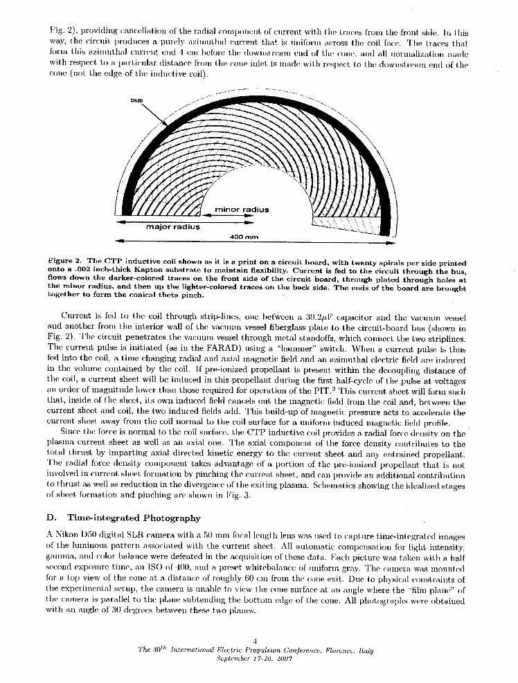
Fig. 2), providing cancellation of tile radial component of current with tile traces from tile ['rout side. In this
way, the circuit produces a purely azimuthal current that is uniform across the coil face. The traces that
form this azimuthal current end ,1 cm I)eforc the downstream end of the cone, and all normalization made
with respect to a particular distance l'rom the cone inlel, is made with respect to the downstream end of the
cone (not tile edge of the inductive coil).
bus
major radius400 mm
Lv
Figure 2. The CTP inductive coil shown as it is a print on a circuit board, with twenty spirals per side printedonto a .002 inch-thick Kapton substrate to maintain flexibility. Current is fed to the circuit through the bus,flows down the darker-colored traces on the front side of the circuit board, through plated through holes atthe minor radius, and then up the lighter-colored traces on the back side. The ends of the board are broughttogether to form the conical theta pinch.
Current is fed to the coil through strip-lines, one t)egween a 39.2pF capacitor and the vacuum vessel
and another from the interior wall of the vacuum vessel fiberglass plate to the circuit-board bus (shown in
Fig. 2). The circuit penetrates tile vacuum vessel through metal standoffs, which connect the two striplines.
The current pulse is initiated (as ill the FARAD) using a :'hmmner" switch. When a current pulse is thus
fed into the coil, a time changing radial and axial magnetic field and an azimuthal electric field are induced
in the volmne contained by the coil. If pre-ionized propellant is present within the decoupling distance of
the coil, a current sheet will be induced in this propellant during the first half-cycle of the pulse at voltages
an order of lnagnitudc lower than those required tbr operation of the PIT. 3 This current sheet will form such
that, inside of the sheet, its own induced field cancels out the magnetic field from the coil and, between the
current sheet and coil, the two induced fields add. This build-up of magnetic pressure acts to accelerate the
current sheet away from the coil normal to the coil surface for a uniform induced magnetic field profile.
Since the torce is normal to the coil surface, the CTP inductive coil provides a radial tbrce density on the
plasma current sheet as well as an axial one. The axial component of the tbrce density contributes to the
total thrust by imparting axial directed kinetic energy to the current sheet and any entrained propellant.
The radial force density component takes advantage of a portion of the pre-ionized propellant that is not
involved in current sheet formation by I)inching the current sheel, and (:an provide an additional contribution
to thrust as well as reduction in the divergence of the exiting plasma. Schematics showing the idealized stages
of sheet tbrmation and pinching are shown in Fig. 3.
D. Time-integrated Photography
A Nikon D50 digital SLR camera with a 50 mm focal length lens was used to cat)ture tinm-integrated images
of the luminous pattern associated with the current sheet. All automatic compensation for light intensity,
gamnm., and color balance were defeated in the acquisition of these data.. Each picture was taken with a half
second exposure time, an IS() of 100, and a preset whitebalance of mnlbrm gray. The camera was mounted
tor a top view of tile cone at a distance of roughly 60 cm from the cone exit. Due to physical constraints of
the experimental setup, the camera is unable to view the cone surface at an angle where the "film plane" of
tile camera is parallel to tile plane subtending the bottom edge of tile cone. All photographs were obtained
with an angle of 30 degrees between these two planes.
4
The 30 th International Electric Propulsion Conference, Florence, Italy
Scptc.'mbc'r 17-20, 2007

Figure 3. Idealized schematics showing current sheet formation (left panel) and pinching (right panel) in theCTP-FARAD.
The picture frame includes the lower half of the inside cone surface, allowing determination of the intensityand extent of the luminous structure from the cone's inlet to its outlet. The aperture is remotely opened,the switch is then activated sending the current pulse through the coil, and the aperture closes automaticallyafter one half second.
III. Experimental Results
A. Interpretation of the Images
While the steady-state argon discharge from the RF source fills the cone with a gas radiating pink light, thisdistinct luminosity is greatly overpowered by an azimuthally-symmetric bright blue discharge that emanatesfrom inside of the cone when the switch is closed. We make the assumption that the intensity, location andextent of this latter luminous structure along the wall of the cone are highly related to those of the currentsheet. However, previous study of current sheets between plane electrodes8 using high-speed imaging and Bdot probes showed high correlation between the current carrying structures and their luminous signatures. Inour study, the use of time-integrated photography implies a loss of some of this correlation since the luminousstructure is more a representation of both the regions where the current has passed at some time duringthe pulse and those containing radiating gas that does not carry current. Moreover, since the current sheetpresumably moves away from the cone's inner surface during the pulse, there is a parallax error associatedwith determining its location along the cone's surface from time-integrated photographs obtained with acamera whose film plane is not parallel to the cone's axis of symmetry.
Due to these limitations we take the measured intensity, location and extent of the luminous structurethat appears during the pulse as rough representations of the corresponding features of the current sheetand limit our conclusions to only relative changes in these measured quantities.
B. Image Processing
All image processing is performed in MatLab. The images are filtered for blue light to increase the signal tonoise ratio. To further increase the signal to noise ratio, a first photo that includes a current sheet is takendirectly before a second photo with no current pulse (but with the background RF plasma on), and thissecond image is subtracted from the first to eliminate a large fraction of the background light associated withthe steady-state RF discharge. This procedure is repeated five times for a given condition and the intensityvalues are averaged. Intensity values on a line along the cone surface are plotted with respect to distancefrom the cone inlet. When distance from the cone inlet is normalized, it is normalized to the cone outlet,which occurs at 13.5 em from the cone inlet. The edge of the inductive coil occurs at 9.5 em from the coneinlet, and corresponds to a normalized distance of .7. The resulting axial profiles are also integrated andnormalized to their peak values to provide a measure of the intensity and extent of the luminous structure.
5The 30th International Electric Pmpulsion Confel-ence, Flol'ence, Italy
September 17-20, 2007
C. Measured Profiles and Pressure Dependencies
The RF power sonrcf' wns held com:tant at 200W forward power and 1%reflected power. No applied mngrlPticfiled was employed and the voltage on the capacitor was maintained at 1.25 kV for each pulse. The argonback-fill pressure in the CTP vacuum vessel W1lS varied from 4 lilT up to 48 mT.
Figure ·1 shows intellsity profiles alollg the cone's wall with the inlet located 1lt 0 cm ellld the exit atl.3.5 cm. Representative profiles from eight back-fill pressure levels spanning the range of varied pressure areshown. The small peak at the latter location is due to light reflection from the downstream edge of the cone.
100!---4_5mT I 100
1---gmT IBO SO
>. 60 coil exil~ 60 ~ ~1i .. .. ..c c c c..
40..
40.. ..:s :s :s :s
20 20
05 10 0 5 10 5 10 5 10
Dislanee(em) Dislanee(em) Dislanee(em) Dislanee(em)
100 100 100 100
BO BO1-33mTI
801-36mTI 1-4smTI
BO>. 60 ~ 60 ~ 60 >. 60"" 1i.. ..c c c c..
40..
40..
40..:s :s :s :s 40
20 20 20 20
0 05 10 0 5 10 0 5 10 5 10
Dislanee(em) Distanee(em) Dislanee(em) Distanee(em)
Figure 4. Profiles of intensity (in arbitrary units) versus distance from inlet along the cone's wall for eightback-fill pressure levels spanning the back-fill pressure range
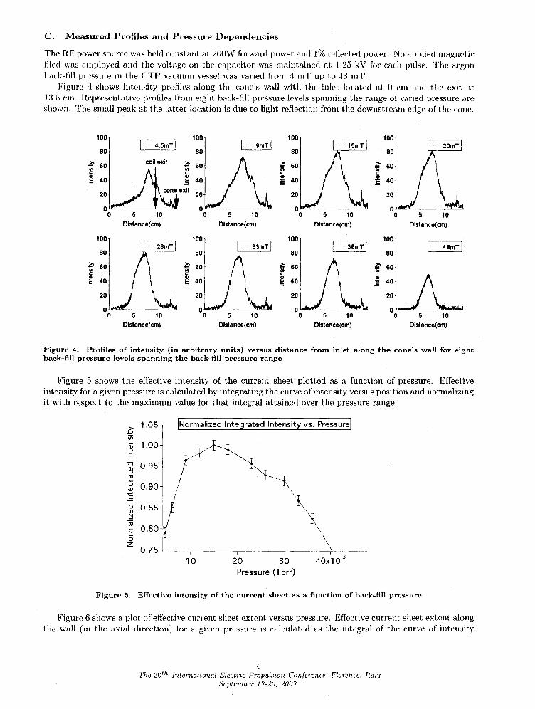
Figure 5 shows the effective intensity of the current sheet plotted as a function of pressure. Effectiveintensity for a given pressure is calculated by integrating the curve of intensity versus position and normalizingit with respect to the maxiuHun value for that integral attained over the pressure range.
INormalized Integrated Intensity vs. Pressuref
40x10-320 30
Pressure (Torr)10
>- LOS..,.iiic 1.00CIl..,.f:
" 0.95CIl..,ro...01 0.90CIl..,.f:
" 0.85CIl
.r:::!(ij
0.80E...0z
0.75
Figure 5. Effective intensity of the current sheet as a function of back-fill pressure
Figure 6 shows a plot of effective current sheet extent versus pressure. Effective current sheet extent alongtlte wall (in the axial direction) for a given pressme is c1llculated as the integral of the cmve of intensity
6The 30 th Intf~T'national EleetTic Propulsion Confer-ence, Flor'cncc. Italy
Scptcmber- 17-2U. 2UU7

versus t)osition divided t)y the peak intensity tor that pressure and normalized to the maxinmm current sheet
exteut attained over the pressure range.
1.0_ _, [Normalized Extent vs. Pressure]
/',,T___, _!u'/ ""
L.-I \,
._ 0.7- \..
"%%70 o.6 -,_
i i i.3I
10 20 30 40x 10
Pressure (Torr)
Figure 6. Effective axial extent (along the wall) of the current sheet as a function of back-fill pressure. The
values of the extent are normalized by the largest value.
The effective location is determined by calculating the eentroid for each curve of intensity versus distancefrom the cone inlet. The centroid locations are normalized by the distance between the cone inlet and exit
(13.5 cm), with the cone inlet and beginning of the inductive coil at 0, the inductive coil ending at .7, andthe exit at 1, and plotted vcrsus back-fill pressure in Fig. 7.
0.7-
.-_ 0.6
o, o.s-._Z'_: o.4-
_c 0.3
N= 0.2
o 0.1-z
0.0-
INormalized Centroid Location vs. Pressure I
1 '0 2'0 3'0 40x'10 -'_
Pressure (Torr)
Figure 7. Effective location (along the wall) of the current sheet as a function of back-fill pressure. The
locations are normalized so that the cone inlet and beginning of the inductive coil are at O, the end of the
inductive coil is at .7, and the cone exit is at 1.
D°
From
1.
2.
3,
Observations
the experiments and the plots of Figs. 4-7, we make the following observations:
Current sheets of varying intensity, extent and location were observed to form at each of the back-fill
pressure levels in the investigated range (4 to 48 reTort).
There is an optimal back-fill pressure, P* (between 10 and 15 reTort for the particular conditions
of this experiment), for which both the clfcctive intensity and extent of the current sheet are largest(Figs. 5 and 6).
The rate of change in effective intensity (and extent) with pressure differs on eit her side ol this optimalpressure, Specifically, the growth rate of intensity (and extent) with increasing pressure below P* issignificantly higher than its decay rate with increasing pressure above P*.
7
The 30 th International Electric Propulsion Conference, Florence, Italy
Hcptembc'r 17-20, 2007

4. For pressure levels below P', the current sheet intensity profiles are not sylllmetric and are relativelymore extended towards the calle exit. Above P' they become 1110re synlllletric with respect to coneinlet and cone outlet (Fig. ;1), but at all vres:mres the current sheet favors the downstream eml of theinducl ivp coil.
5. For all pressure levels ill the illvestigate range, current sheet formation occurs around the middle sectionof the cOlle but strollgly favors the dowllstream half of the illductive coil. As call be seell ill Fig 7,current sheet formation occurs at normalized distances of 0.5 to 0.56 from the inlet, while the end ofthe coil occurs at .7.
G. As t.h<~ prpssnre risps the dfective location of currpnt shpet formation moves Rlightly, hut ddinitely andmonotonically, towards the inlet (Fig. 7).
We proceed by using these qualitative observations to glean some basic aspects of the mechanisms underlying current sheet formation in such a device.
IV. Discussion and Interpretation of the Observations
The existence of an optimal pressure (Observation 2) is indicative of a Townsend-like breakdown. On thelower-pressure side of P', due to the relatively lower neutral density, the electrons involved in current sheethreakdown undergo fewCf ionizing collisions with the hackground neutrals, while on the higher pressure sideof that optimum they gain less energy from the electric field between collisions because their mean free pathbetween collisions with neutrals is smaller.
Uulike iu the c1as:;ic Towusend breakdowu, however, there is a finite steady-state backgortlnd electrondensity from the steady-state RF discharge in FARAD without which breakdown would require far largerpulse energies. Measurements of a similar RF argon discharge at fixed RF input power of 200 W werereported by Chang et al. 9 and are reproduced in Fig. 8. These data show that the electron density increaseswith pressure over the pressure range of our experiment. (Of course this increase cannot go indefiuitely atconstant power as the energy input per unit mass decreases with increasing pressure.)
5 10 15Pressure (Torr>
20
Figure 8. The effect of pressure on electron number density in a 13.56 MHz RF inductive discharge. 9
The reported increase of electron density with back-fill pressure implies that the decrease in ion productionrate due the lower average electron energy on the high-pressure side of P* is, to some extent, counterbalancedby the increase iu the !Hnnber of background e1ectrous. This would explain the lower rate of decrease in thecurrent sheet's intensity and extent vs pressure at that side of the optimum relative to their increase rate onthe lower-pressure side (Observation 3).
It is well know in pul:;ed plasma thruster research that the current sheet tend::; to form ill such a way thatthe inductance presented to the circuit is minimized. 2 For the conical theta pinch, this implies a curn'ntsheet forming at a location that serves to exclude as much coil-generated magnetic: flux from the interior
8The 30th International Electric Propulsion Conference, Florence, Italy
Sqltcmbcl' 17-ZU. ZUU7

volume of the (:oil. A current sheet forming at the downstream end of the coil eircmnscribes a larger area
circle than a current sheet forming fitrther upstream. This may explain why the current sheet favors tiledownstreanl location.
In addition, a current sheet, lorming at the downstream edge of the induclive coil will tend to affect
magnetic flux lines fiarther upstream, forcing them to stay close to the walls of the theta-pinch to maintain
V-B -- 0. A current sheet forming near the upstream end, consisting of a smaller ring current, will not have
nearly the same effect <m the magnetic field lines in the rest of the theta pinch's interior. Consequently, the
point of lowest inductance, and the point where the sheet is predisposed to form, is at or near the downstream
end of the inductive coil. This may explain why the current sheet has an asymmetric extent favoring the
exit end of the coil (OI)servation 4) and why current sheet fbrmation (at all the investigated pressure levels)
is biased (to a varying degree) towards the downstream end o[ the inductive eoil (Observation 5). Because
tile circuit board traces end 4 cm before the cone outlet, current sheet formation is less dramatically biased
toward tile exit half of the cone as it is biased towards the downstream edge of" the inductive coil.
The remaining observation (Observation 6) that current sheet formation has a tendency to move upstream
with increasing pressure may be explained through a consideration of the inductive circuit shown in Fig. 9.
R< Lo Switch
C Ij
Figure 9. Schematic of the inductive circuit used to explain observation 6
The resistivity of a weakly ionized plasma., such as the background RF-produeed plasma, in CTP-FARAD,
is dominated by eleetron-imutral collisions. As the pressure increases, the frequency of these collisions
increases, increasing the resistivity in the preionized plasma. During the inductive pulse, the plasma has
a resistance Rp that is equal to the resistivity integrated around the circumference of the coil. This value
increases for a given axial location as a function of pressure and for a given pressure it decreases as we
move axially towards the inlet. From a circuit point-of-view, we recognize that the voltage drop across the
transformer nmst bc equal to the voltage drop owing to the plasma resistance. This would require the currcnt
sheet to initially form filrther upstream in the theta-pinch coil as the pressure and Rp increase at a given
axial location. Consequently, in a pulsed inductive discharge the sheet may be forced to form at a location
other than the point of minimum overal circuit inductance.
V. Summary and Concluding Remarks
A photographic study of the effects of back=fill pressure on the intensity, extent and location of current
sheets in a conical theta pinch FARAD thruster provide some basic insights into the mechanisms regulating
current sheet formation. The existence of an optimal pressure for maximum sheet intensity and strength
and the difference in the rates of change in these quantities with changing pressure on either side of this
optimum were explained as the behavior of a _ibwnsend-like breakdown modulated by a background electron
density that increases with pressure. The effective axial location (along the wall) aromld which the sheet
tends to form, and its dependence on pressure, are thought to be related to a dynamic balance between tile
resistive elements (depending on plasma resistivity and, thus, pressure) and inductive elements (depending
on the axial location inside the conical coil) of all equivalent inductive circuit.
Future work will aim at verifying and consolidating these insights with more analytical diagnostics and
models, with the ultimate goal of deriving prescriptions for optimizing current sheet formation and evolution
as a [im('tion of controllable operating parameters, inchlding the mass flow rate through the device, applied
inagnetic field and RF power.
9
The 30 th International Electric Propulsion Conference, Florence, ItalyScptcmbcr 17-20, 2007

o
Acknowledgments
This research project is carried out under a contract from tile the Air Force Office of Scientific Research.
Wc also acknowledge support from tile Plasma Science and Technology Program fl'om ttlc Princeton Plasma
Physics Laboratory. We thank Mr. Robert Sorenson ['or his valuable technical supt)ort and [or the 3-D
illustrations of the CTP-FARAD concept.
References
1R.H. Lovberg C.L.Dailey. Large diameter inductive pla.sma thrusters. Number AIAA 79-2093. oct 1979.
2R.. G. Jahn. Physics of Electric Propulsion. McGraw-Hill Book Company, 1968.
aE. Y. Choueiri and K. A. Polzin. Faraday acceleration with radio-frequency assisted discharge. Journal of Propulsion and
Power, 22(3):611 619, May-June 2006.
4K. A. Polzin and E. Y. Choueiri. Performance optimization criteria for pulsed inductive plasma acceleration. IEEE
Transactions on l)lasma Science, 34(3):945 953, 2006.
5C.L. Dailey and R.H. Lovberg. Current sheet structure in an inductive-impulsive plasma accelerator. AIAA Journal,
10(2):125-192, Feb. 1972.
6R.H.Lovberg C.L.Dailey. Pit mark v design. Number AIAA 91-3571, 1991.
7R. II. Lovbcrg C. L. l)ailey. The PiT MkV pulsed inductive thruster. 'lkwhnical report, Lewis Research Center, 1993.
ST.E. Markusic and J. W. Berkery E. Y. Choueiri. Visualization of current sheet evolution in a pulsed plasma accelerator.
IEEE Transactions of Plasma Science, 33(2):528-529, April 2005.
9C. Chang, K. Leou. and C. Lin. Real-time control of ion density and ion energy in chlorine inductively coupled plasma
etch processing. JouT_al of vacuum Science and Technology, 21(4):1183 1187, July 2003.
10
The 30 th [nternational Electric Propulsion Conference, FIorcnce, Italy
Scptcmbcr 1"720, 2007