Embed Size (px)
Citation preview

1 . Report No. 2. Government Accession No.
FHWA/TX-96!1370-1
4. Title and Subtitle
CURRENT PRACTICE IN THE REPAIR OF PRESTRESSED BRIDGE GIRDERS
7. Author(s) lisa R. Feldman, James 0. Jirsa, David W. Fowler, and Ramon L. Carrasquillo
9. Performing Organization Name and Address
Center for Transportation Research
Technical Report Documentation Page
3. Recipient's Catalog No.
5. Report Dote August 1993 Revised June 1996
6. Performing Organization Code
8. Performing Organization Report No.
Research Report 1 370-1
10. Work Unit No. (TRAIS)
The University of Texas at Austin 11. Contract or Grant No. 3208 Red River, Suite 200 Research Study 0-1370 Austin, Texas 78712-1075
1------------~----------------l 13. Type of Report and Period Covered 12. Sponsoring Agency Nome and Address
Texas Department of Transportation Research and Technology Transfer Office P.O. Box 5080 Austin, TX 78763-5080
15. Supplementary Notes
Interim
14. Sponsoring Agency Code
Study conducted in cooperation with the U.S. Department of Transportation, Federal Highway Administration. Research study title: "Repair of Impact-Damaged Prestressed Concrete Girders"
16. Abstract
This report includes a literature search of currently utilized repair techniques, the Texas Department of Transportation's survey of current practice in the repair of impact-damaged prestressed concrete girders, a survey of current practice in the U.S. and Canada, an approach to the repair of impact-damaged prestressed girders, and findings of the first phase of the field study.
17. Key Words 18. Distribution Statement
Bridge girders, repair techniques, impact-damaged prestressed girders, current practice
No restrictions. This document is available to the public through the National Technical Information Service, Springfield, Virginia 22161.
19. Security Classif. {of this report]
Unclassified
Form DOT F 1700.7 !8-721
20. Security Classif. (of this page)
Unclassified
Reproduction of completed page authorized
21 . No. of Pages
86
22. Price


CURRENT PRACTICE IN THE REPAIR OF PRESTRESSED BRIDGE GIRDERS
by
Lisa R. Feldman
James 0. Jirsa
David W. Fowler
and
Ramon L. Carrasquillo
Research Report Number 1370-1
Research Project 0-1370
"Repair of hnpact Damaged Prestressed Concrete Girders"
conducted for the
Texas Department of Transportation
in cooperation with the
U.S. Department of Transportation
Federal Highway Administration
by the
CENTER FOR TRANSPORTATION RESEARCH
Bureau of Engineering Research
THE UNIVERSITY OF TEXAS AT AUSTIN
August 1995 Revised March 1994 Revised June 1995 Revised June 1996


NOT INTENDED FOR CONSTRUCTION, BIDDING, OR PERMIT PURPOSES
James 0. Jirsa, P.E. (Texas No. 31360) David W. Fowler, P.E. (Texas No. 27859)
Ramon L. Carrasquillo, P.E. (Texas No. 63881) Research Supervisors
The contents of this report reflect the views of the authors, who are responsible for the facts and accuracy of the data presented herein. The contents do not necessarily reflect the views of the Texas Department of Transportation. This report does not constitute a standard, specification, or regulation.
iii


PREFACE
This report presents a literature search of currently utilized repair techniques for impact-damaged prestressed bridge girders. the results of a survey of current practice of all TxDOT districts. a survey of current repair practice in the United States and Canada. and an approach to the repair of impactdamaged prestressed girders within the context of the field study of this project. The approach suggested for the repair of impact-damaged girders includes damage assessment and a discussion of repair techniques for strength. durability. and aesthetic restoration. The information received provides an indication of the state of the art in impact damage repair within the United States and Canada.
v

vi

SUMMARY
Repair of impact-damaged prestressed bridge girders continues to vex engineers. It is difficult to assess the condition of a damaged girder and to confidently design a repair scheme which will perform well for the intended service life of the bridge. An average of approximately one girder per week is damaged in Texas as a result of overheight loads. Current practice in Texas indicates that minor damage is routinely ignored, moderate damage is patched, and severely damaged girders generally are replaced. The survey of current practice substantiates the need for assessing the effectiveness of concrete and strand repairs by the implementation of a field testing program to determine the long-term performance of damaged or repaired elements.
vii

viii

IMPLEMENTATION
The approach for the repair of impact-damaged prestressed bridge girders included in this report should serve as an aid to engineers involved in bridge design and maintenance repair of impact damage. In the proposed repair procedure, the restoration of structural integrity, re-establishment of bridge appearance, and structural durability are considered.
ix

X

TABLE OF CONTENTS
CHAP1ER 1 ..............................................................•..............................................................................•.....•..... 1 INTRODUCTION ............................................................................................................................................... ]
1.1 Problem History .................................................................................................................................... 1 1.2 Research Significance ........................................................................................................................... 1 1.3 Research Objectives ............................................................................................................................. 2
CHAP1ER 2 ......................................................................................................................................................... 3 liTERATURE SEARCH STATE OF THE ART- REPAIR OF IMPACT DAMAGED PRESTRESSED BRIDGE GIRDERS ............................................................................................................................................ 3
2.1. Introduction ......................................................................................................................................... 3 2.2. Dantage to Concrete ............................................................................................................................ 3 2.3. Repairs to Concrete ............................................................................................................................. 3
2.3.1. Cementitious Patching Materials ...................................................................................... 3 2.3.2. Alberta Transportation and Utilities Classification of Cementitious Patching
Materials ......................................................................................................................... 4 2.3.3. Epoxy Injection ............................................................................................................... 5 2.3.4. Preloading ....................................................................................................................... 5
2.4. Dantage to Prestressing Strands ........................................................................................................... 6 2.5. Restoration of Prestressing Force ........................................................................................................ 6
2.5.1. External Post-Tensioning .................................................................................... ~ ............ 6 2.5.2. Internal Splicing ............................................................................................................... 6 2.5.3. Metal Sleeve Splices ........................................................................................................ 6 2.5.4. Combination Splice Methods ........................................................................................... 7 2.5.5. Girder Replacement ......................................................................................................... 7 2.5.6. Comparison of Splicing Techniques ................................................................................ 7
CHAFfER 3 .........••....................•........................................................•...................................•.....•..............•....... 9 SURVEY OF CURRENT PRACTICE ................................................................................................................. 9
3.1. Number of Impact Dantage Incidents From 1987 to 1992 ................................................................... 9 3.1.1. Impact Damage From 1987 to 1992 ................................................................................. 9 3.1.2. Minimum Vertical Clearance and Impact Dantage ........................................................ 10
3.2. Dantage Inspection and Evaluation .................................................................................................... 11 3.2.1. Personnel. ....................................................................................................................... 11 3.2.2. Field Procedures Used to Determine the Extent ofDantage .......................................... 11 3.2.3. Information Included in the Dantage Report .................................................................. 11 3.2.4. Analytical Procedures Used to Determine the Extent ofDantage .................................. 13
3.3. Repair Procedure Determination ....................................................................................................... 13 3.3.1. Relative Importance of Factors Influencing the Selected Repair Procedure .................. 13 3.3.2. Personnel Responsible for Determining the Repair Procedure ...................................... 13 3.3.3. Personnel Responsible for Plans and Specifications ...................................................... 13
3.4. Dantage Repair .................................................................................................................................. 14 3.4.1. Repair of Minor Dantage ............................................................................................... 14 3.4.2. Repair of Moderate Dantage .......................................................................................... 14 3.4.3. Repair of Severe Dantage ............................................................................................... 16
3.5. Status Of Repair Methods In The State OfTexas .............................................................................. 16
xi

CHAFfER 4 ........................................................................................................................................................ 17 CURRENT PRACTICE IN THE UNITED STATES AND CANADA. ................................................................ 17
4.1 number of impact-damage incidents from 1987 to 1992 .................................................................... 17 4 .1.1 Impact Damage from 1987 to 1992 ................................................................................ 17 4.1.2 Minimum Vertical Clearance and Impact Damage ......................................................... 18
4.2 damage inspection and evaluation ...................................................................................................... 18 4.2.1 Personnel. ........................................................................................................................ 18 4.2.2 Field Procedures Used to Determine the Extent of Damage ........................................... 19 4.2.3 Information Included in the Damage Report ................................................................... 19 4.2.4 Analytical Procedures Used to Determine the Extent of Damage ................................... 19
4.3 repair procedure determination ........................................................................................................... 21 4.3.1 Relative Importance of Factors Influencing the Selected Repair Procedure ................... 21 4.3.2 Personnel Responsible for Determining the Repair Procedure ....................................... 22 4.3.3 Personnel Responsible for Plans and Specifications ....................................................... 22
4.4 damage repair ..................................................................................................................................... 22 4.4.1 Repair of Minor Damage ................................................................................................ 22 4.4.2 Repair of Moderate Damage ........................................................................................... 22 4.4.3 Repair of Severe Damage ................................................................................................ 22
4.5 status of repair methods in the united states and Canada .................................................................... 25
CHAFfER S ......................................................................................................................................................... 27 APPROACH FOR THE REPAIR OF IMPACT-DAMAGED GIRDERS .......................................................... 27
5.1 Assessing the Degree of Damage ........................................................................................................ 27 5.1.1 Visual Observation .......................................................................................................... 28 5.1.2 Non-Destructive Testing Methods .................................................................................. 28 5.1.3 Damage Classification .................................................................................................... 28 5.1.4 Observed Damage Patterns ............................................................................................. 28
5.2 Minor Damage Repair ........................................................................................................................ 30 5.2.1 Removal of Loose and Damaged Concrete ..................................................................... 32 5.2.2 Patching the Damaged Area ............................................................................................ 32 5.2.3 Aesthetic TreatmenUPainting/Coloring of the Girder Surface ........................................ 33
5.3 Moderate Damage Repair ................................................................................................................... 33 5.3.1 Removal of Loose and Damaged Concrete ..................................................................... 34 5.3.2 Cleaning Exposed Tendons and Stirrups ........................................................................ 34 5.3.3 Pre1oading the Structure .................................................................................................. 34 5.3.4 Epoxy Injection and Sealing of Cracks ........................................................................... 34 5.3.5 Patching the Damaged Area ............................................................................................ 34 5.3.6 Aesthetic TreatmenUPainting/Coloring of the Girder Surface ........................................ 35
5.4 Severe Damage Repair ....................................................................................................................... 35 5 .4.1 Removal of Loose and Damaged Concrete ..................................................................... 38 5.4.2 Cleaning Exposed Tendons and Stirrups ........................................................................ 38 5.4.3 Tendon Repair Methods .................................................................................................. 38 5.4.4 Epoxy Injection and Sealing of Cracks .......................................................................... .40 5.4.5 Patching the Damaged Area ............................................................................................ 40 5.4.6 Aesthetic TreatmenUPainting/Coloring of the Girder Surface ........................................ 40
5.5 An Example of the Approach for the Repair oflmpact-Damaged Girders ........................................ .40 5.5.1 Inspection of Damage ..................................................................................................... 41 5.5.2 Repair Approach ............................................................................................................. 42
xii

CHAPTER 6 ........................................................................................................................................................... 45 SUMMARY, CONCLUSIONS, AND RECOMMENDATIONS .......................................................................... 45
6.1 Sununary ........................................................................................................................... 45 6.2 Conclusions ....................................................................................................................... 45 6.3 Reconunendations ............................................................................................................. 45
Appendix A -- Survey Fonn ............................................................................................................. 47
Appendix B -- Out-of-State Survey Fonn ...................................................................................... 55
Appendix C -- Participating States and Provinces ........................................................................ 63
References ........................................................................................................................................... 65
xiii

LIST OF FIGURES
Figure 2- I External post-tensioning (48) ............................................................................................................ 6 Figure 2- 2 Internal splice (7) .............................................................................................................................. 7 Figure 2- 3 Metal sleeve splice jacketing the girder at the location of the severed strand ( 48) ........................... 7 Figure 3- I Impact damage between I987 and I992 ........................................................................................... 9 Figure 3- 2 Distribution of bridge clearances (Interstates, U.S. and State Highways, Loops, and Spurs) in
Texas ............................................................................................................................................... IO Figure 3- 3 Bridge clearances versus the number of damaged bridges .............................................................. 10 Figure 3-4 Personnel responsible for inspection on projects in Texas .............................................................. II Figure 3- 5 Field procedures used to determine the extent of damage on projects in Texas .............................. I2 Figure 3- 6 Information included in the damage report on projects in Texas .................................................... I2 Figure 3- 7 Relative importance of factors influencing the selected repair procedure in Texas ........................ 13 Figure 3- 8 Personnel responsible for determining repair procedures on projects in Texas .............................. I4 Figure 3- 9 Personnel responsible for plans and specifications in Texas districts ............................................. I4 Figure 3- 10 Repair procedures for minor damage on projects in Texas ............................................................. I5 Figure 3- II Repair procedures for moderate damage on projects in Texas ........................................................ I5 Figure 4- I Impact damage between I987 and I992 ......................................................................................... I8 Figure 4-2 Bridge clearance versus the number of damaged bridges ................................................................ I8 Figure 4- 3 Personnel responsible for inspection on projects ............................................................................ I9 Figure 4- 4 Field procedures used to determine the extent of damage ............................................................... 20 Figure 4- 5 Information included in the damage report ..................................................................................... 20 Figure 4- 6 Relative importance of factors influencing the selected repair procedure ....................................... 2I Figure 4- 7 Personnel responsible for determining the repair procedure ........................................................... 23 Figure 4- 8 Personnel responsible for plans and specifications ......................................................................... 23 Figure 4- 9 Repair procedures for minor damage .............................................................................................. 24 Figure 4- 10 Repair procedures for moderate damage ......................................................................................... 24 Figure 4- II Repair procedures for severe damage ............................................................................................. 26 Figure 5- 1 Impact damage assessment .............................................................................................................. 27 Figure 5- 2 Minor damage (Courtesy of the Manitoba Highways and Transportation) ..................................... 29 Figure 5- 3 Moderate damage (Courtesy of the Texas Department of Transportation) ..................................... 29 Figure 5- 4 Severe damage (Courtesy of Washington Department of Transportation) ...................................... 30 Figure 5-5 Common crack pattern following side impact. ................................................................................ 30 Figure 5- 6 Loss of side cover example (Courtesy of Texas Department of Transportation) ............................ 31 Figure 5- 7 Loss of side cover ........................................................................................................................... 31 Figure 5- 8 Minor damage repair ....................................................................................................................... 32 Figure 5-9 Moderate damage repair .................................................................................................................. 33 Figure 5- 10 Severe damage repair ...................................................................................................................... 36 Figure 5- 11 Damage to an exterior girder ........................................................................................................... 37 Figure 5- 12 Instrumentation of exterior girder ................................................................................................... 37 Figure 5- 13 Transverse section of Steck A venue bridge .................................................................................... 38 Figure 5- 14 Installation and restressing anchors to ends of severed strands ....................................................... 39 Figure 5- 15 Retensioning operation of severed strands ...................................................................................... 39 Figure 5- 16 Transverse section of College Station bridge ................................................................................ ..41 Figure 5- 17 Girder I -College Station bridge (Courtesy of the Texas Department of Transportation) .......... .41
xiv

Figure 5- 18 Girder 11 - College Station bridge (Courtesy of the Texas Department of Transportation) ........ .43 Figure 5- 19 Girder 13-College Station bridge (Courtesy of the Texas Department ofTransportation) ......... 43
XV

Table 2- 1
Table 2-2
LIST OF TABLES
Alberta Transportation and Utilities Classification ofCementitious Patching Materials (9) ............ 5
Strand Repair Method Comparison (48) ........................................................................................... 8
xvi

CHAPTER!
INTRODUCTION
In 1980, the National Cooperative Highway Research Program, Project 12-21, "Evaluation of Damage and Methods of Repair for Prestressed Concrete Bridge Members," revealed that nearly 200 bridges were damaged per year, and that 80 percent of those were damaged by over-height vehicles and loads (47). It is unlikely that these statistics have shown any reduction in the intervening period, considering increased traffic volume and the number of bridges.
1.1 PROBLEM HISTORY
A literature search identified a very limited number of publications (7, 8, 37, 47, 48, 66) which relate to the repair of impact-damaged prestressed concrete girders. The two NCHRP Reports, Nos. 226 and 280, are the only references which provide extensive information.
NCHRP Project 12-21 consisted of two phases. In the first phase, a comprehensive assessment of methods of damage evaluation and repair of prestressed concrete bridge members was undertaken. The results were published in NCHRP Report 226, "Damage Evaluation and Repair Methods for Prestressed Concrete Bridge Members." The second phase led to specific guidelines for evaluation of damaged girders as was based on the results of laboratory tests on a girder that was repaired using various techniques including external post-tensioning, internal splicing of severed strands, and metal splice sleeves. The techniques were intended for repair in place. The second phase resulted in the publication of NCHRP Report 280, "Guidelines for Evaluation and Repair of Prestressed Concrete Bridge Members."
While Project 12-21 provided much useful information on repair techniques and included a survey of types of damage and repair procedures used by various state departments of transportation, there is a need for further study of this problem. It is likely that in the 12 to 15 years that have elapsed since the survey was conducted, many other damaged girders have been evaluated and repaired. In addition, the "damaged" girder studied in Project 12-21 was not damaged by impact but was damaged in the laboratory by removing cover and severing strands. The same girder was used for a series of 10 different tests. Such a procedure is likely to be cost-effective but will not produce the kind of damage likely to occur when girders are impacted in the field. Field-damaged girders need to be studied. In addition, the repair techniques in Project 12-21 were aimed primarily at the restoration of severed strands and the addition of posHensioning or a splice sleeve. Such techniques may produce beams with different appearance, and introduce durability problems. These techniques also do not address the problem of repairing damage which may be quite extensive, such as the lateral deformation of the bottom flange of the beam due to impact (which does not result in obvious damage or severing of tendons).
1.2 RESEARCH SIGNIFICANCE
Repair of impact-damaged prestressed bridge girders continues to vex engineers. It is difficult to assess the condition of the damaged girder and confidently design a repair scheme which will perform well for the intended service life of the bridge. The work done previously under NCHRP
1

Project 12-21 forms the basis for this project. The intent is to extend the work done under Project 12-21 to provide bridge engineers with an array of damage evaluation and repair approaches.
In the years since Project 12-21 was completed, the area of non-destructive testing methods has advanced significantly. Such techniques can be used to acquire data which will enable much more detailed evaluation of existing conditions. In addition, new materials which can be used in repair are commercially available, and their application to bridge repair problems needs to be examined.
The present study will be based primarily on the analysis of field-damaged girders. An investigation and evaluation of damaged girders is likely to lead to developing a method for making decisions regarding repair or replacement. Other aspects of the study include examination of repair methods through laboratory studies.
1.3 RESEARCH OBJECTIVES
The objectives of the overall study of the repair of impact-damaged prestressed bridge girders are:
1. To survey types of damage observed and repair techniques undertaken by T:xDOT.
2. To develop procedures for estimating the degree of damage to girders and to assess the strength and expected performance of a bridge containing damaged and/or repaired elements. The evaluation procedure will make use of current non-destructive techniques that can quickly and practically provide the data necessary for reliable predictions of the strength of the damaged girders for making a decision regarding repair or replacement.
3. To develop repair procedures that result in durable, easily maintained bridge structures.
4. To investigate and recommend procedures for long-term monitoring and evaluation of repair techniques. The monitoring activity may accompany the Bridge Management System (BMS) currently being developed by Texas DOT.
The report presented herein concerns the first phase of the work performed in the project, including a literature search of currently used repair techniques, the results of a survey of current practice of all T:xDOT districts, a survey of current repair practice in the United States and Canada, and an approach to the repair of impact-damaged prestressed girders within the context of the first portion of the field study of this project.
Chapter 2 of this report includes a discussion of existing repair techniques. In Chapter 3, the results of the TxDOT survey of current practice are presented, and in Chapter 4, this survey and a survey of current practice in the United States and Canada are compared. An approach to the repair of impact damage is presented in Chapter 5 within the context of the initial field evaluations conducted as part of this research project. General conclusions and recommendations are found in Chapter 6. Several appendices are included, displaying the survey forms used to acquire data, and the list of participating states and provinces.
2

CHAPTER2
LITERATURE SEARCH STATE OF THE ART- REPAIR OF IMPACT DAMAGED PRESTRESSED BRIDGE GIRDERS
2.1. INTRODUCTION
A literature search on the repair of impact-damaged prestressed bridge girders was performed utilizing the library facilities at the Center for Transportation Research at The University of Texas at Austin. The search revealed that very little research has been conducted in this field. Repair procedures available for use by the Texas Department of Transportation were identified. A detailed listing of the references cited in this literature review, as well as background material, is contained in the reference section of this report.
Impact damage to a prestressed concrete bridge girder may consist of damage to the concrete and to the prestressing strands. Therefore, the repair of damaged girders requires knowledge of both concrete repairs and prestressing strand repair techniques. Impact damage and specific repair strategies will be discussed in the following sections. Emphasis will be placed on methods that will restore girder aesthetics, durability, and/or strength, as this will aid in understanding the merits and limitations of the repair methods.
2.2. DAMAGE TO CONCRETE
Impact damage to a prestressed concrete girder may consist of cracks, nicks, spalls, scrapes, loss of significant cross section, and beam distortion resulting in lateral misalignment.
2.3. REPAIRS TO CONCRETE
Two general categories of concrete repairs exist: the repair of concrete spalls and loss of cross section, and the repair of concrete cracks.
2.3.1. Cementitious Patching Materials.
Cementitious patching materials are normally used to repair concrete spalls and to replace damaged or removed cross section. The patching materials must be compatible with the base concrete in a given member; otherwise, a premature failure of the patch or the surrounding concrete could occur. Factors to be considered include: freeze-thaw cycles, exposure to deicing salt, extreme temperatures, rapid temperature changes, and dynamic and static loading (9).
All cementitious patching materials shrink as they dry. Preferably, most of this shrinkage occurs soon after casting, while the patch is still plastic and has not fully bonded to the concrete. If the selected patch material shrinks excessively after it has hardened and bonded to the base concrete, significant stresses will occur at the interface due to this shrinkage, and the repair material may crack or debond from the base concrete. Shrinkage can be minimized by using a low water-to-cement ratio, and by extending the patch material with coarse aggregate (23). Low-shrinkage or expansive grouts may be useful in some cases.
3
The two basic mechanisms which could lead a patching material to undergo thermal changes are: the heat of hydration of the patch material, and the expansion of the material due to changes in ambient temperature. The chemical reactions that take place while a cementitious patch material hydrates produce heat. As the patch cools to the ambient temperature, internal tensile stresses will be produced that can cause cracking and debonding. As well, the coefficient of thermal expansion can vary between concretes and patching materials. If the repaired member is exposed to elevated temperatures, differential movement between the base concrete and the patch material can result in debonding of the patch. Thermal expansion can be minimized by extending the patch material with coarse aggregate (43).
In general, the higher the permeability of a concrete, the less durable it is. Permeability controls the rate of entry of moisture into the concrete, either as liquid or as vapor, that may contain detrimental chemicals such as deicing salts, and controls the movement of water during heating and freezing (32). The patch material should have a permeability compatible with that of the base concrete. The durability will be improved if the patch material has a lower permeability than the base concrete.
For a structural type of repair, the compressive strength of the patch material should be as high as, if not higher than, that of the base concrete, since the repaired member is likely to be subjected to the same loading conditions that existed prior to being damaged. The elastic modulus of the patch material should be as close as possible to that of the original concrete. A patch material with a modulus higher than that of the base concrete will tend to carry a greater portion of the load, while a patch material with a lower modulus will not carry as much of the load as the base concrete. However, for most impact-damaged beams, patching will be limited to the bottom flange (the tension zone of the girder). Therefore, the effect of the modulus on subsequent girder performance will be reduced. However, it is important that the patch be well bonded to the base concrete to avoid failure at the interface between the patch and the base material.
Rapid strength gain allows for the return of the structure to service as quickly as possible. The most common way to achieve rapid strength gain is through the use of high early strength concrete. However, the faster a patch material sets, the more linear shrinkage will occur once the patch has hardened (23). In addition, it should be considered that high early strength concretes have a lower later age strength than do normal concretes.
The quality of the bond between the concrete and the patch is primarily governed by the surface preparation of the base concrete (23, 44, 46, 59). There is general agreement that in order to ensure adequate bond, all loose and delaminated material should be removed and the surface should be free of any dust that may reduce bond strength (14, 44, 46, 50, 56, 57, 64). Repair delaminations can be reduced if feathered edges are eliminated by providing a saw kerf at the perimeter of damaged areas.
2.3.2. Alberta Transportation and Utilities Classification of Cementitious Patching Materials.
In May 1992, the Government of Alberta, Canada, prepared a document for the specification for concrete patching materials for use by their province. This document is cited as reference 9 in the reference section of this report.
Compressive strength, shear bond strength, water absorption rate, linear shrinkage, and salt scaling were all evaluated for several dry, packaged cementitious mortars and concrete materials for the repair of concrete structures (9). Each material tested was given a rating between 1 and 10 for each of the five criteria as listed above, as described in Table 2.1. An average of the five ratings was taken for each material tested, and products with an average rating below 6.0 were rejected.
4

Table 2-1 Alberta Transportation and Utilities Classification of Cementitious Patching Materials (9)
Rating Compressive Strength Shear Bond Volume of Permeable Unear Shrinkage1'1 Salt Scaling
(MPa) Strength Solids(%) (%) Mass Loss (MPa) (kg/m2
)
1 <34.0 <2.0 > 11.5 >0.18 1.2 2 34.0 to35.9 2.1 to 3.5 9.6 to 11.5 -0.160 to- 0.179 0.975 to 1.199 3 36.0 to 37.9 or 84.0 3.6to 5.0 7.6to 9.5 -0.140to .0.159 0.775 to 0.974 4 38.0 to 39.9 or 80.0 to 83.9 5.1 to 6.5 6.6to 7.5 -o.120 to .0.139 0.600 to 0.774 5 40.0 to 41.9 or 76.0 to 79.9 6.6to 8.0 5.6to 6.5 -o.100 to .0.119 0.450 to 0.599 6 42.0 to 43.9 or 72.0 to 75.9 8.1 to 9.5 4.6 to 5.5 -o.oao to -0.099 0.325 to 0.449 7 44.0 to 45.9 or 68.0 to 71.9 9.6 to 11.0 3.6to 4.5 -o.oso to -0.079 0.225 to 0.324 8 46.0 to 47.9 or 64.0 to 67.9 11.1 to 12.5 2.6 to3.5 -0.040 to -0.059 0.150 to 0.224 9 48.0 to 49.9 or 60.0 to 63.9 12.6 to 14.0 1.6 to 2.5 -0.020 to -o.039 0.100 to 0.149 10 50.0to 59.9 >14.0 1.5 < ·0.020 <0.100
(1) Negative values represent shrinkage strains.
Table 2.1 shows rating determinations for the compressive strength of 1.95 in. (50-mm) cubes cured for 28 days. Compressive strength tests were performed as per CSA CAN3-A5. Shear bond tests were done according to ASTM C882, Standard Test Method for Bond Strength of Epoxy - Resin Systems Used With Concrete. The shear bond test method determines the bond strength of patch materials cast onto slanted surfaces of 28-day-old 30 MPa concrete (9). The absorption rate was monitored using 150-mm x 150-mm x 50-mm specimens cured for 14 days, according to a procedure similar to ASTM C642, Standard Test Method for Specific Gravity, Absorption and Voids in Hardened Concrete. Linear shrinkage testing was performed according to ASTM C 157. Shrinkage of specimens was measured at 1 day while still in the mold, 3, 7, and 28 days from the time of casting the specimen. Loss of mass due to salt scaling was measured after 50 cycles in accordance with ASTM C672, Standard Test Method for Scaling Resistance of Concrete Surfaces Exposed to Deicing Chemicals. ASTM C672 is used to determine the resistance to scaling of a horizontal surface exposed to freeze-thaw cycles in the presence of deicing salts (9).
For products suitable for overhead and vertical patching, in other words products suitable for impact repair, only two products received a rating above the required 6.0. One product received a 6.0 rating, while another product received a 6.4 rating. No other products for overhead or vertical patching were listed in the conclusions of this report.
2.3.3. ~ Injection.
Epoxies are very effective for sealing cracks. Epoxies produce a high strength bond between concrete and concrete, and are 100 percent solids and therefore do not undergo shrinkage or curing. Cracks as narrow as 0.002 in. (.0508 mm) can be injected with epoxy (2, 60).
Epoxies bond the concrete surfaces together and help restore structural integrity. They also seal the cracks, thereby reducing undesired exposure conditions and associated increased rates of deterioration of reinforcing steel and prestressing strands (49). Tests show that epoxy-repaired cracks tend to be stronger than the original concrete; therefore, new cracks may develop adjacent to these repaired cracks if the cause of distress has not been eliminated (29).
2.3.4. Preloading.
Preloading involves loading the damaged girder with dead weight, by means of trucks, sandbags, etc., while repairs are taking place. The preloading force should cause a downward deflection of the
5

Polyethylene concrete grout after post tensioning
Jacking Corbel
Figure 2-1 External post-tensioning (48)
girder to restore girder shape, and to allow the patched concrete to be in compression under dead load. In addition, preloading can be used to open up cracks in the tension zone of the beam to facilitate epoxy injection.
2.4. DAMAGE TO PRESTRESSING STRANDS
Damage to prestressing strands due to impact damage can include nicks, strand yielding, and severed strands. Indirect damage to tendons includes: the dislocation of tendons due to a loss of concrete cross section, and accelerated corrosion potential due to loss of concrete cover and hence exposure to the elements.
2.5. RESTORATION OF PRESTRESSING FORCE
A nick in one wire in a seven-wire strand is not considered serious since even if the wire eventually cracks because of fatigue, the failure does not cause propagation to other wires (48). However, more serious damage, such as severed strands, may require repair in order to restore original or nearoriginal prestressing force to a given damaged girder. The following sections list repair techniques that have been developed for restoring prestressing force.
2.5.1. External Post-Tensioning.
External post-tensioning, as shown in Figure 2.1, uses concrete corbels cast against the damaged girder as jacking points for high strength steel rods or prestressing strands (48). The size and strength of the jacking corbels dictate the number of severed strands that can be repaired by means of external post-tensioning.
2.5.2. Internal Splicing.
Internal splicing methods use hardware, as shown in Figure 2.2, to re-couple and re-tension a severed strand. The hardware is used to torque the splice to the desired prestressing force.
2.5.3. Metal Sleeve Splices.
Figure 2.3 shows a metal sleeve splice capable of replacing a large number of severed strands ( 48) and can be used to repair girders with a significant loss of cross section. The steel plates can be painted to match the color of the concrete to restore girder aesthetics.
6

Coupler Restressing Gauge Restressing Device
Figure 2-2 Internal splice (7)
In the work reported in Ref. 48, it was recommended that for splicing 6 strands or less, the sleeve should lap the severed strands 5 ft. 3 in. ( 1.60 meters) minimum, and for splicing more than 6
Steel Plates
Figure 2-3 Metal sleeve splice jacketing the girder at the location of the severed strand ( 48)
strands, the sleeve should lap the severed strands 160 strand diameters. This was determined by testing a girder with Y2-in. (12.7 mm) strands. The strength of the sleeve was transferred to the beam by epoxy grout between the sleeve and the concrete (48). Bond stress of the steel-concrete connection may control the allowable number of strand splices at the interface.
2.5.4. Combination Splice Methods.
A combination of internal and external splice methods may be useful in a single girder. Metal sleeve splices can be used in combinations as well, even though they can normally, on their own, replace the prestressing force of a large number of severed strands (48).
2.5.5. Girder Replacement.
Girder replacement is normally the most expensive and time-consuming option (47, 48). However, girder replacement guarantees full
restoration of girder strength, durability, service life, and aesthetics. There are many instances, especially in bridges with low clearances, where replaced girders are hit again.
2.5.6. Comparison of Splicing Techniques.
Table 2.2, as developed by Shanafelt and Hom, cites the advantages and disadvantages of the aforementioned strand repair methods.
7

Strand Repair Method Comparison ( 48)
Factor I External Post· Tensioning Internal Splicing Metl'lOdS I Metal Sleeve Splice 1 Girder Replacement Service and Ultimate Load caoacitv Excellent Excellent Excellent Excellent
Overload Capacity Excellent Excellent Excellent Excellent Fati!.'IIJe Excellent Umited Excellent Excellent
Addina Strenath to Non-Damaaed Girders Excellent Not ADDiicable Excellent Not Applicable Combinina SDiice Methods Excellent Excellent Excellent Not Applicable
SDiicina Tendons or Bundled Strands Umited Not Applicable Excellent Excellent Number of Strands SDilced Umited Umited Large Unlimited
Preload Reauired Perhaps Yes Possible No Restore Loss of Concrete Excellent Excellent Excellent Excellent
Soeed of Reoair Good Excellent Good Poor Durability Excellent Excellent Excellent Excellent
Cost Low VervLow Low Hiah Aesthetics Fair Excellent Excellent Excellent
8

CHAPTER3
SURVEY OF CURRENT PRACTICE
A survey form was compiled and sent to all of the Texas Department of Transportation (TxDOT) districts. The survey was the primary tool in determining the current practice in repair of impact damage in the state of Texas. The information obtained from this survey was used to determine the research agenda for the project and to establish the direction and focus of future research.
Twenty-three out of the twenty-four TxDOT districts responded to the survey, resulting in a 96 percent participation rate. Therefore, the statistics and trends in repair procedures discussed in this chapter should provide an accurate reflection of the current practices in the repair of impact-damaged prestressed girders in the state of Texas.
The survey form itself, shown in Appendix A, consisted of two sections: the General Information Survey, and the Specific Project Survey. The General Information Survey was designed to obtain information on typical repair procedures for damaged girders. The goal of the Specific Project survey was to develop a performance database of repaired girders and the repair methods that have been or are currently being used in Texas. The survey addressed damage and repairs only within the five-year period between 1987 and 1992. It should be noted that the survey form permitted respondents to check more than one answer to a number of the questions. As a result, the responses may add to more than 100% or more than the number of surveys returned in many cases.
3.1. NUMBER OF IMPACT DAMAGE INCIDENTS FROM 1987 TO 1992
Damage was classified as minor, moderate, or severe. Minor damage was defined as concrete cracks and nicks, shallow spalls, and/or scrapes. Girders with large concrete cracks, and spalls large enough to expose undamaged prestressing tendons, were classified as moderately damaged. Severe damage included exposed damaged tendons, or loss of significant portions of concrete cross section, as well as possible girder distortion resulting in lateral misalignment.
3.1.1. Impact Damage From 1987 to 1992.
The number of impact-damaged prestressed bridge girders between 1987 and 1992 is shown in Figure 3.1. Although a record of minor damage is often not kept by some of the districts, minor damage accounted for two thirds of all reported impact damage. One-fifth of all damage was classified as moderate,
200r-----------------,
"0
f 150 c ~ ... ~
100 a
~ 50 ::I z
Figure 3-1
9
158*
Minor
* Not all districts keep a record of minor damage
Moderate
Degree of Damage
Severe
Impact danu2ge between 1987 and 1992

1000 3303 and slightly over one-eighth of total
<1.1
~ 800 ;§ '0600
1400
200
0 2 3 11 12.5 13.0 13.5 14.0 14.5 15.0 15.5 16.0 16.5
Figure 3-2
Minimum Vertical Clearance (ft.)
Distribution of bridge clearances (Interstates, U.S. and State Highways, Loops, and Spurs) in Texas.
bridge damage was severe. In all, 241 girders were damaged within Texas in the five-year survey period, indicating an average of about one girder damaged every week within the state.
3 .1.2. Minimum Vertical Clearance and Impact Damage.
Specifications require that bridges built in the state of Texas in 1993 have a minimum vertical clearance of at least 14 ft. - 6 in. (4.42 m). However, recommended practice is to keep minimum vertical clearance above 16 ft. - 6 in. (5.03 m). Figure 3.2 shows a distribution of the number of bridges in 6-in. (152.4 mm) increments of minimum vertical clearance. All data shown in this figure were extracted from BRlNSAP, the Texas De
partment of Transportation Bridge Inventory, Inspection and Appraisal Database System. As shown in Figure 3.2, 38 percent of all prestressed concrete bridges on the Texas system of Interstates, U.S. and State Highways, Loops and Spurs, have vertical clearances less than the current suggested 16 ft. -6 in. (5.03 m) minimum vertical clearance. Data shown in Figure 3.2 were limited to heavily traveled routes, such as state highways and loops, likely to have a high number of large vehicles traveling on them. As well, the TxDOT is responsible for maintaining all of the selected route types.
The distribution of minimum vertical bridge clearances for the reported impact-damaged bridges is shown in Figure 3.3. As shown, 53 of the damaged bridges (some bridges had multiple damaged girders), or 85 percent of the total number of damaged bridges, had vertical clearances below 16ft.-6 in. (5.03 m). Note that the number of bridges damaged by over-height loads does not necessarily coincide with the number of girders damaged, since more than one girder on a given bridge can be
Minimum Vertical Clearance (ft.)
Figure 3-3 Bridge clearances versus the number of damaged bridges
10
damaged when the bridge is struck by an overheight vehicle.
The probability of a given bridge being struck by an over-height vehicle is a function of the minimum vertical clearance of the bridge and the traffic pattern on the given route. The heavier the traffic pattern, and the greater the number of heavy vehicles traveling the route, the more likely a given bridge is to be hit. Lower vertical clearance bridges tend to be confined to secondary routes. No correlation between minimum vertical bridge clearance and impact damage can therefore be established from the results of this project, since traffic patterns on the various routes containing the damaged bridges have not been studied.

3.2. DAMAGE INSPECTION AND EVALUATION
The TxDOT districts were surveyed to determine the personnel responsible for the inspection of damaged prestressed concrete bridges, the field procedures used to determine the extent of damage, the information included in the damage report, and the analytical procedures used to determine the structural extent of the impact damage.
3.2.1. Personnel.
The survey indicated that most inspections are done by private consultants, district design/bridge engineers, or the district maintenance engineers. More than one of these groups may be used to inspect the same project. This information is shown in Figure 3.4. The level of participation by private consultants appears to be overestimated in the responses to the questionnaire. Some respondents must have included routine bridge safety inspections, which are performed by private consultants, in this category and not limited their response to impact-damaged girder inspection.
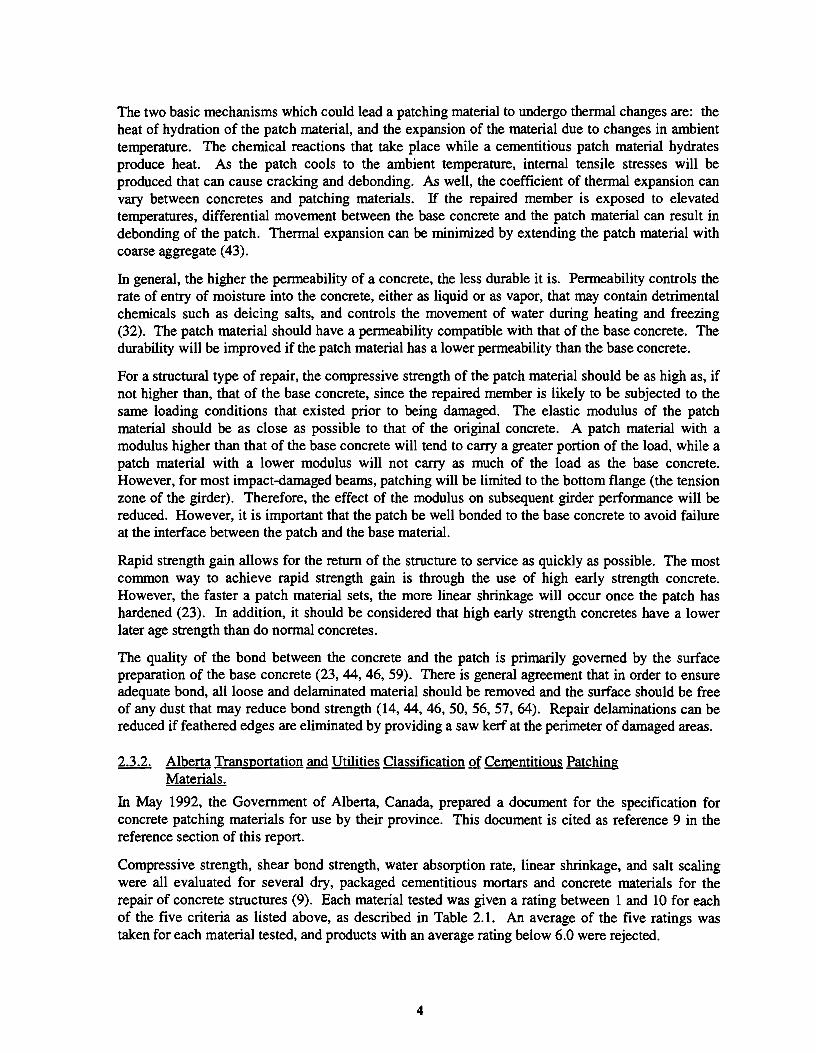
3.2.2. Field Procedures Used to Determine the Extent of Damage.
Out of the specific repair jobs discussed in the survey, 88 percent were inspected only visually, while 12 percent of cases were examined by means of non-destructive testing methods (ranging from hammer sounding to coring) as well. These data are presented in Figure 3.5.
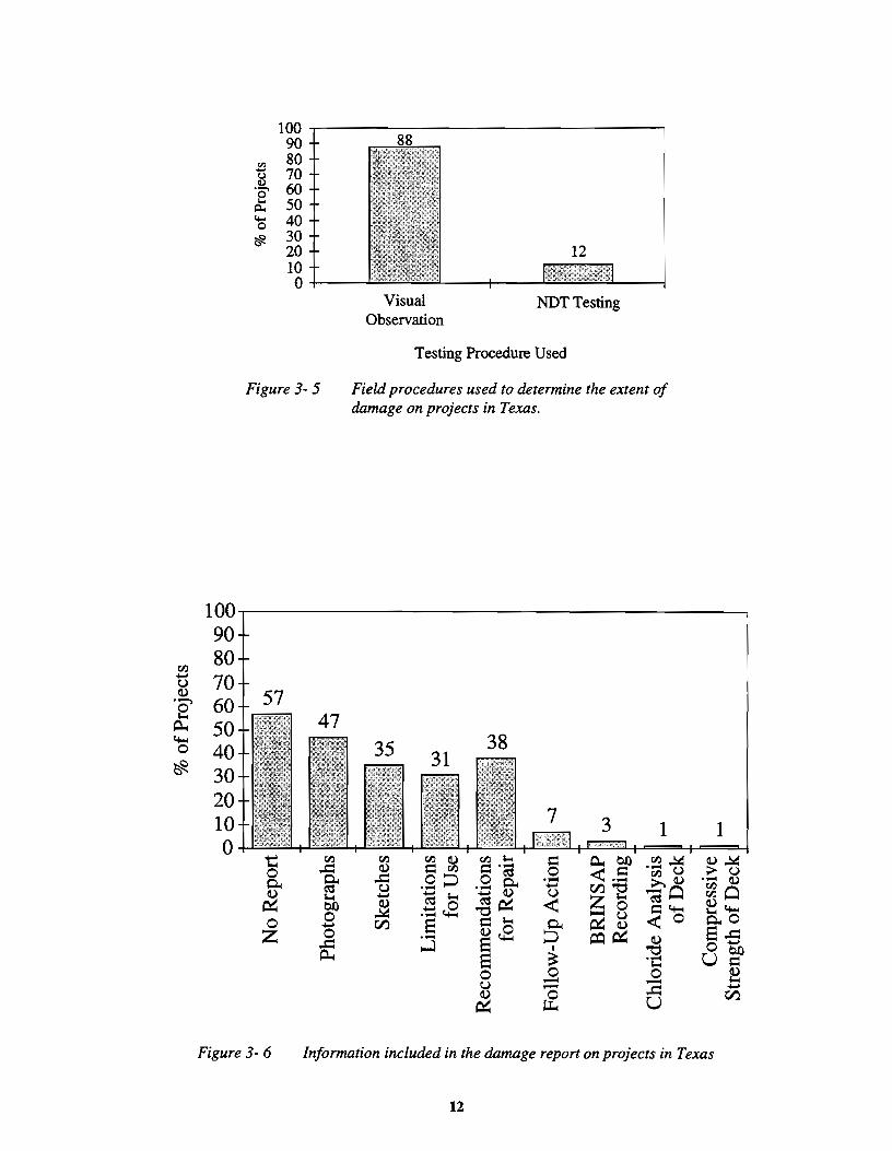
3.2.3. Information Included in the Damage Report.
As illustrated in Figure 3.6, no report was filed for over half of impact-damaged prestressed girder cases between 1987 and 1992. Half of the cases were photographed, one third had sketches of cracks and/or damage, and one third included recommendations for continued or limited use of the structure. Other responses included: recommendations for further work associated with the damage, recommendations for recording the damage incident in the BRINSAP database, the results of a
47
0
Figure 3-4 Personnel responsible for inspection on projects in Texas
11
tl.) -u a)
• '="'>
£ 4..; 0
~
100 90 80 70 60 50 40 30 20 10 0
100~------------------------------~ 90 80
~ 70 '§' 60 j;l,. 50 'S 40 ~ 30
20 12 10 0+---
Figure 3-5
57
t tl.)
0 ..t:: 0.. ~ ~ $-t
b.O 0 0 -z 0 a:
Visual Observation
NOT Testing
Testing Procedure Used
Field procedures used to determine the extent of damage on projects in Texas.
1
.~ ~ tl.) tl.) a) tl.) $-t ~ P,.,.b.O a) = tl.) ~·a 0 < .s tl.) u ..t:: .9 !:J .9 0.. ·- >,a)
B - tll"' ~ $-t - a) u "";0 ] C':::$~ < Z""' ·"= c.S ~-eO =4..; "0
~g < 0 til E = $-t 0.. ·- a,)c.S !:J ~~ a) ...J E I "0
E ~ ·-$-t
0 0 0 u - -- ..t:: a) & ~ u
1 a)~ > u ·- a) ~0 a,)4..; ~0 E.s Ob.Q u~
~ -til Figure 3-6 Information included in the damage report on projects in Texas
12

chloride analysis of the bridge deck, and the results of a compression strength test of the bridge deck concrete.
3.2.4. Analytical Procedures Used to Determine the Extent of Damage.
In only three out of the sixty-eight reported cases of impact damage, slightly more than 4 percent of all cases, an analysis procedure was used. In the other cases, only visual inspection of the damaged girders was carried out. In two cases, the state or district bridge office uses PSTRS 14, Prestressed Concrete Beam Design/Analysis Program, to analyze girders with broken strands. In one case, a hand analysis was performed to determine the structural capacity of the damaged girder.
3.3. REPAIR PROCEDURE DETERMINATION
The determination of a repair procedure for a given impact-damaged girder depends on the judgment and prior experience of the person responsible for selecting the repair method, and the factors influencing such a repair. For instance: damaged bridges in heavy traffic areas are normally repaired by the quickest method available with the least interruption to traffic.
3.3.1. Relative Importance of Factors Influencing the Selected Repair Procedure.
Factors such as time, interruption of service, and cost influence the selection of a repair method for a damaged girder. Each district was asked to rate seven factors in terms of high, moderate, or low priority when selecting a repair method. A weighted average of all survey responses was conducted: 3 points for a high rating, 2 points for a moderate rating, and one point for a low rating.
According to the surveyed TxDOT districts, factors of greatest importance in determining a repair procedure include: interruption of service (2.8) and the load capacity of the repaired girder (2.6). The lowest priorities included the cost of the repair and the aesthetics of the repair. Other responses of high priority included: follow-up action, public safety, type of facility, future plans for the bridge,
>. 1\) ~ :s rl) ..... 0
f < ] ..c 01)
·;u :::
5~----------------------------~
3
2
0
Other Responses of High Priority:
... "' 8
Public Safety Type of Facility Future Plans for the Bridge Condition of the Entire Bridge
1\)13 "' 6 8 -o >. u eu.-:: E '"' ·~ ·.:::·:; .31i ~=·g. c.. .... .s e~ c.. 1\) "' "' "
1\) <U"'" u < :so
Traffic Count Location
.!:! 8 ;:s 1::
"' 8 1:: J!l ·;;: 1:: .. ·a 1\)
rl) ~
Figure 3- 7 Relative importance of factors influencing the selected repair procedure in Texas
13
traffic count, location, and condition of the entire bridge. These ratings are shown in Figure 3.7.
3.3.2. Personnel Responsible for Determining the Repair Procedure.
As shown in Figure 3.8, the district maintenance engineer is most frequently responsible for determining the repair procedure. The district construction engineer or private consultants were rarely consulted in the repair process. For a given project, several groups may be involved.
3.3.3. Personnel Responsible for Plans and Specifications .
Plans and specifications are most often prepared by the district design bridge engineer, followed by Bridge Design (Austin), the district maintenance engineer, and the area engineer. A private consultant was never used to prepare the plans and specifications for an impact damaged

Figure 3-8 Personnel responsible for determining repair procedures on projects in Texas
repair of a prestressed girder. These results are illustrated in Figure 3.9. Different groups may be involved on various projects in a district.
3.4. DAMAGE REPAIR
3.4.1. Repair of Minor Damage.
Two thirds of incidents of minor damage that were noted on the survey were not repaired. As illustrated in Figure 3.10, the most common repair procedure for the girders sustaining minor impact damage between 1987 to 1992 involved patching the concrete. In a few cases the girder surface was repainted or coated with an epoxy cover. More than one procedure was often indicated for the same project.
3.4.2. Repair of Moderate Damage.
Only 14 percent of the girders with moderate damage were not repaired, as shown in Figure 3.11. Moderate damage in the state of Texas is most often repaired by patching the girder with concrete or a
100
80
J!l (J ·s 60 "' i5 '0 40 ~
20
Figure 3-9
14
80 More than one group may be involved in a district on a project
65
0
Personnel responsible for plans and specifications in Texas districts

80
60
20
More than one procedure may have been used for a project
q) .c .......... () () C!J ....
{g ~ .c C!J ... >
:s 0. 0 8 "' C!J ... - >. c ~ >< ·a () 0
c fr 0. 0 ~ u '-'
Figure 3-10 Repair procedures for minor damage on projects in Texas
Figure 3-11
£ c:: ~
0 (.) ·~ c:: :::s ;....
0 c;f.) t'$ (I) (.) 0..
~ .c:: ;.... >. ~ a (I) -...... >< Q.. (I) 0.. ·- .c:: 0 - C!J ~ - £" u 0 0::: .c:: ;....
~ 0
Q..
Repair procedures for moderate damage on projects in Texas
15

conunercially available patching material, and removing loose concrete and preparing the surface before patching. In about two thirds of cases, cracks were injected with epoxy. In two cases, the girders were replaced to avoid patching the girders above traffic and running the risk of the patches eventually debonding from the existing concrete and falling onto traffic below.
3.4.3. Repair of Severe Damage.
In 25 percent of cases of severe damage, severed strands were not repaired. The girders were simply patched with cracks epoxy·injected in some cases (83% were patched; only 62% were injected).
In only one case of severe damage recorded between 1987 and 1992 were the severed strands in a girder actually repaired. The repair consisted of using internal splices to repair the severed strands. The concrete repair of this girder involved preparing the girder surface by removing loose concrete, and using concrete or a conunercially available product to patch the area. The cracks were not injected with epoxy.
In the remaining projects the girders were replaced. In one case of severe damage, all of the girders on the damaged span were replaced with box girders to increase the minimum vertical clearance of the bridge.
3.5. STATUS OF REPAIR METHODS IN THE STATE OF TEXAS
The State of Texas has not developed and tested a procedure for repairing severed strands in damaged prestressed girders. Minor damage to girders is routinely ignored, moderate damage is patched, and severely damaged beams tend to be replaced.
16

CHAPTER4
CURRENT PRACTICE IN THE UNITED STATES AND CANADA
The current state of technology for the repair of impact-damaged prestressed girders was determined from the results of a survey sent to all of the TxDOT districts. The survey fonn itself is shown in Appendix A, and the results of this survey are discussed in detail in Chapter 3. The TxDOT survey bad a 96 percent participation rate.
Once the TxDOT survey had been completed, the survey fonn was modified, and was sent to the remaining forty-nine states as well as ten Canadian provinces and territories. The information obtained from this out-of-state survey was used to determine the current state of practice regarding the repair of impact-damaged prestressed concrete bridge girders by other transportation agencies nationwide and in Canada.
The out-of-state survey fonn, shown in Appendix B, had the same general structure as the survey sent to the TxDOT districts. The survey fonn consisted of two sections. The General Information Survey was designed to obtain information on typical repair procedures for damaged girders. The goal of the Specific Project Survey was to develop a performance database of repaired girders and the repair methods that have been, or are currently being used, in the United States and Canada. The survey addressed only damage within the five-year period between 1987 and 1992.
Respondents of the out-of-state survey are listed in Appendix C. Thirty-four out of the remaining forty-nine states responded to the survey, resulting in a 67 percent participation rate in the United States. Seven out of ten surveyed Canadian provinces and territories responded to the survey, resulting in a 70 percent Canadian participation rate. Overall, a 68 percent participation rate was obtained for the out-of-state survey. The statistics were based on responses from 33 states and 7 provinces. These statistics and trends in repair procedures provide an indication of the current state of the art in the repair of impact-damage prestressed bridge girders in the United States and Canada.
4.1 NUMBER OF IMPACT-DAMAGE INCIDENTS FROM 1987 TO 1992
Impact damage was classified as minor, moderate, or severe. Minor damage was defined as concrete cracks and nicks, shallow spalls, and/or scrapes. Girders with large concrete cracks, and spalls large enough to expose undamaged prestressing tendons, were classified as moderately damaged. Severe damage included exposed damaged tendons, or loss of significant concrete cross section, as well as possible girder distortion resulting in lateral misalignment.
4.1.1 Impact Damage from 1987 to 1992
The proportions of damage classified as minor, moderate and severe are similar for both Texas and the other states and provinces, as shown in Figure 4.1. Two-thirds of damage in Texas and threefifths of damage in other states and provinces was classified as minor, even though a record of minor damage is not kept by some states and provinces. Slightly over one-fifth of damage in Texas and one-quarter of damage in other states and provinces was classified as moderate, and approximately one-eighth of total bridge damage was severe.
17

In all, 241 girders were damaged within Texas during the five-year survey period, and 1,008 girders were damaged in all other participating states and provinces. Texas accounts for one-fifth of all surveyed damage, thus reflecting the large number of lane miles of highway in Texas and the high percentage of prestressed bridge girders used on the Texas highway system.
4.1.2 Minimum Vertical Clearance and Impact Damage.
Specifications require that bridges built in the state of Texas have a minimum vertical clearance of at least 14ft.- 6. in. (4.42 m). However, recommended practice is to keep minimum vertical clearance above 16 ft. -6 in. (5.03 m).
1000 • Texas
13 ~ 800 ~ Other States and Provinces ~ Q el 600 v
"E a '0 400 .... v e ::I
200 z
0 Minor Moderate Severe
Degree of Damage
Figure4-1 Impact damage between 1987 and 1992
The distribution of minimum vertical bridge clearances for the reported impact damaged bridges is shown in Figure 4.2. As shown, 85 percent of the total number of damaged bridges in Texas had vertical clearances below 16ft. - 6 in. (5.03 m). Ninety-three percent of the total number of damaged bridges in the other states and provinces had vertical clearances below 16ft.- 6 in. (5.03 m). Note that the number of bridges damaged by overheight loads does not necessarily coincide with the number of girders damaged; more than one girder can be damaged when a bridge is truck by an overheight load.
4.2 DAMAGE INSPECTION AND EVALUATION
All states and provinces were surveyed to determine the personnel responsible for the inspection of impact-damaged prestressed concrete girders, the field procedures used to determine the extent of damage, the information included in the damage report, and the analytical procedures used to determine the structural extent of the impact damage.
4.2.1 Personnel.
Inspection is most often performed by the state bridge division, followed by the district design/bridge engineer. At times, more than one office inspects the same project. This information is shown in Figure 4.3. It should be noted that the responses from Texas to this question may have been skewed by misinterpretation of the questionnaire. The results should be viewed with that in mind (see Sec. 3.2.1).
20
"' 16 ., QO .., ·c 11:1
il 12 lljl E ..
Q .... 0
.8 E "' z
Figure 4-2
18
• Texas
~ Other States and Provinces
14.0 14.5 15.0 15.5 16.0 16.5+ Minimum Vertical Clearance (ft.)
Bridge clearance versus the number of damaged bridges

80 • Texas
~Others OTHER RESPONSES
60 59
50 Texas (50%): i!l Area Engineer (1 0%) u ~ Bridge Inspector (35%) '0'
40 ... BRINSAP Section (4%) Q. ...
0
~ Others (5%): 20 State Structures Division (2.5%)
Maintenance Superintendent (2.5%)
0 NOTE: More than one group - ... ... ~
c: ... ~ ... .... i~ ~ .2 ~ ooo .5 may be used for a Q) ~
:g~ ·- c: c: .::: c: "' ·- "bi) :; "bi) 0 project Q) 00
"' ;> j;gC..
0 c: til c: a c: "' -Ill 0 Ill - c: u-u Q) 8 u ~ c: ·s ·~~ c: ~ ~ ·E l5 ·- ·c «< ·c t:lj;g c: ;> I:Q :::1
~ if 1::: c: B "' ·a s c
0 ::E l'll u
Figure4- 3 Personnel responsible for inspection on projects
4.2.2 Field Procedures Used to Detennine the Extent of Damage.
As shown in Figure 4.4, the TxDOT survey yielded the same ratio of visual observation to nondestructive testing methods as the out-of-state survey for the specific impact-damaged cases reported by all of the participating states and provinces. For every nine cases that were inspected visually, only one case was also examined by means of non-destructive testing methods, ranging from hammer sounding to coring.
4.2.3 Information Included in the Damage Report
As illustrated in Figure 4.5, no report was filed for over half the impact-damaged prestressed bridges in Texas between 1987 and 1992, while in other states and provinces, only five percent had no report filed.
In Texas, half of the damage cases were photographed, one-third had sketches of cracks and/or damage, and one-third included recommendations for continued or limited use of the structure. In the other states and provinces, 95 percent of cases were photographed, 88 percent had sketches of cracks and/or damage, 61 percent included recommendations for limitations of structure use, and 61 percent included recommendations for repair of the structure.
4.2.4 Analytical Procedures Used to Determine the Extent of Damage.
In only three out of the sixty-eight reported cases of impact damage in the state of Texas, slightly more than four percent of all cases, an analytical procedure was used to determine the extent of damage. In the other cases, only visual inspection of the damaged girder was carried out.
19

100
.... ... & ~ 0 z
100
80 • Texas ~ Other States and Provinces
Testing Procedure Used
Figure4-4 Field procedures used to determine the extent of damage
95
"' "' ~ ..c:: _g £" 0 B ... ... u l:>()
.:.0: .£ g v.l "' 0 c f 0 ·;::
s ·e ~
Figure4- 5
... ... c 0 ·- .9 ""' «:1 "' it' t) 6~ < .i Q.
0 ""0 c I
u :it E ..9 E & 0 <..) u ~
... ~ 0
• Texas
~ Other States and Provinces
OTIIER RESPONSES
Texas (13%): Follow-Up Action (7%) BRINSAP Recording (3%) Chloride Analysis of Deck ( 1%) Compressive Strength of Deck ( 1%)
Others (5% ): Police Report (2.5%) Feasibility of Repair vs. Replacement (2.5%)
Note: More than one category of infonnation may be included on a report
Information included in the damage report
20

Other states and provinces relied more on analytical procedures to determine the extent of impact damage. Of the fifty reported cases of impact damage, fourteen (28 percent) were verified using some sort of analytical procedure. Of the states specifying their analysis procedure, all but one used an in-house computer software program. The one outstanding case used M-STRUDL to analyze the extent of damage.
4.3 REPAIR PROCEDURE DETERMINATION
The determination of a repair procedure for a given impact-damaged prestressed girder depends on the judgment and prior experience of the person responsible for selecting the repair method, and the factors influencing such a repair. For instance, damaged bridges in heavy traffic areas are normally repaired by the quickest method available and with the least interruption to traffic. Prestressing tendon splicing techniques are a relatively new development, and personnel currently unaware of these methods might recommend replacement of a girder with damaged tendons.
4.3.1 Relative Importance of Factors Influencing the Selected Repair Procedure.
Factors such as time, interruption of services, and cost influence the selection of a repair method for a damaged girder. Each state and province was asked to rate such factors in terms of high, moderate, or low priority when selecting a repair method. A weighted average of all survey responses was conducted: three points for a high rating, two points for a moderate rating, and one point for a low rating.
According to the surveyed TxDOT districts, factors of greatest importance in determining a repair procedure include: interruption of service (2.8), and the load capacity of the repaired girder (2.6). These ratings are shown in Figure 4.6. Other states and provinces rated their highest concerns as : the load capacity of the repaired girder (2.9), and interruption of service (2.6). Both Texas and other
4
3 2.8 2.9 2.62.6
~ 2.4 'g . .,... 2.1 2.1 £ 2 .9 '(5 1.61.5 ~
0 t:: "0 "' Cl) ~ 0 1! .~ u u ·:; u ·;:;: '<::)
.... C<l C" -5 Cl) c. Cl) "' 1'./.l C<l
IX u '- u Cl) < 0 "0 E ;:: C<l
0 j E= ·a :::l t:: £ ;:: -
2.42.4
.s ::l
Cl) 0
-~ u
1'./.l
• Texas
~ Other States and Provinces
2 2.2 2.1 Texas <Others}:
0* Cl) u ~ ;:: ~ C<l C<l = 1'./.l £ = -~ ·a :c
:::s! :::l c.
Public Safety*
Type of Facility
Future Plans for the Bridge
Traffic Count
Location
Condition of the Entire Bridge
NOTE: In the survey form submitted to districts in Texas (Appendix A), Public Safety was not listed but many districts added it under "Other Concerns."
Figure4- 6 Relative importance of factors influencing the selected repair procedure
21

states and provinces had low priorities for aesthetics (1.6 and 1.5, respectively) and cost (1.9 and 2.1, respectively).
4.3.2 Personnel Responsible for Determining the Repair Procedure.
As shown in Figure 4.7, Texas most frequently employs the district maintenance engineer for determining the repair procedure, while the district construction engineer or private consultants were rarely used in the repair process determination. In other states and provinces, the state bridge division is almost exclusively used to determine the repair procedure.
4.3.3 Personnel Responsible for Plans and Specifications.
In Texas, plans and specifications are most often prepared by the district design/bridge engineer, followed by the state bridge division. Other states and provinces use their state bridge division 90 percent of the time to prepare plans and specifications, and the district design/bridge engineer is used 33 percent of the time. These results are illustrated in Figure 4.8.
4.4 DAMAGE REPAIR
4.4.1 Repair of Minor Damage.
Two-thirds of incidents of minor damage that were noted on the TxDOT survey were not repaired, as compared to only one-third of cases in other states and provinces. As illustrated in Figure 4.9, the most common repair procedure for girders sustaining minor damage between 1987 and 1992 involved patching the concrete: 45 percent of girders in Texas were patched as compared with 82 percent in other states and provinces. However, the proportion of girders that have experienced minor concrete spalls cannot be determined from the results of the survey.
4.4.2 Repair of Moderate Damage
As shown in Figure 4.10, 14 percent of the girders sustaining moderate damage in Texas were not repaired, while all girders sustaining moderate damage in other states and provinces were repaired. Moderate damage is most often repaired by removing loose and damaged concrete, preparing the concrete surface, and patching the girder with concrete or a commercially available patching material. The results of the survey imply that the concrete was not prepared before concrete patching in some repair cases. About two-thirds of Texas cases and three-quarters of other cases also injected cracks with epoxy.
In two cases in Texas, the girders were replaced to avoid patching these girders above traffic and running the risk of the patches eventually debonding from the existing concrete and falling onto traffic below. Hawaii had one case in which they added steel channels to the damaged beam to increase its capacity. Montana preloaded a damaged beam before patching the concrete and injecting cracks with epoxy. In Texas, beams are routinely preloaded in standard repair projects.
4.4.3 Repair of Severe Damage
In 25 percent of cases of severe impact damage in the state of Texas, the severed strands, if any, were not repaired, and the girders were simply patched while cracks may have been epoxy-injected. In 11 percent of cases in other states and provinces, the severed strands were not repaired. In 71 percent of severe damage cases in Texas, and 54 percent of cases in other states and provinces, the girders were replaced.
22

100
100
"' .£ "' ~ ... 60 0 s 0 ·;:::: 'iii 40 i5 .... 0
~ 20
0
82
~ c .... 0 ~ ·;;;
"bb ·:;: E ~ Q .., ~ c g "t:) .::
"' ·c t; c IX)
~ B B c ·a s c ::E Vi 8
.... ~ 0
• Texas
~ Other States and Provinces
OTHER RESPONSES:
Texas (13%):
Area Engineer (9%) District Engineer ( 1%) BRINSAP Section (3%)
Others (8% ):
Project Design Engineer (2.7%) District Bridge Crew Supervisor (2.7%) Maintenance Superintendant (2. 7%)
.g NOTE: More than one group may ';;;
0 be responsible on a project
Figure 4- 7 Personnel responsible for determining the repair procedure
89
• Texas
~ Other States and Provinces
OTHER RESPONSES:
Qther States and Provinces (!;i%):
Structures, Maintenance & Investigative Design Section
... ... ... ... (2.7%) = c:: 0 0 0 &l 0 State Maintenance Division (2.7%) 0 s 0 £ c:: c:: ·;;; c:: "tiC "3 "tiC ·;: "tiC 0 Material Supplier (2.7%) "' c:: c c i5 c t.tl 0 t.tl t.tl 0 u 0 0 "' 01) 0 01)
~ "0 B c "0 ·r:: "' "' ·r:: < CQ > .§ CQ NOTE: More than one group 13 ·r:::
E Q. c:: may be responsible in a 01) ·a ·;;; ~ t:ll 0 district or state Q
t) ·r:: 'iii i5
Figure 4- 8 Personnel responsible for plans and specifications
23

100
80
!!! g6Q ~~ p.. '-0 !!?. 40
20
~ :E g 0
Q
100
80
~ 60 ·~ p.. '-0 40 !!?.
20
0 bl) c:
~ c: 0
Q
82
Q.) .c 0 0 ..s ~ .... Q.. = "' B c Q.) ....
.(ij 0 Q.. § Q.) u "'
.... Q.)
-5 0
• Texas
~ Other States and Provinces
OTHER RESPONSES:
Texas (2%):
Epoxy Cover (2%)
Others 08%):
Epoxy Injection (9%) Seal Cracks with Concrete Sealer (3%) Coat Strands with Epoxy (3%) Preload and Inject with Epoxy (3%)
NOTE: More than one procedure may be used on a project
Figure 4~ 9 Repair procedures for minor damage
100
• Texas
~ Other States and Provinces
OTiiER RESPONSES:
Texas <24%):
* Often included in surface preparation (17%) Replace Girder (7%)
Others (8%): '"''ii c: c: "' .... o ·c 0 0 § Q.)
*£ ·:s -5 B v "0 0 Q.) ~ Q.) .... c Add Steel Channels to Beam (4%) g e .a' o:s B Q..
0 .... >. ~ c: Preload Before Patching and Epoxy Injection (4%) ~~ Q.. o:s
>< Q.)
~ 0 0 <:> 0 NOTE: More than one procedure may be used .c cfr .s u .... on a project ~ = p.. Cl)
Figure 4- 10 Repair procedures for moderate damage
24

As shown in Figure 4.11, the most common method of strand repair is the use of internal splices, followed by external post-tensioning. Most common steps in concrete repair are: preparing the surface of the damaged beam, followed by patching the concrete, epoxy-injection of cracks, and recasting the girder and deck portion.
4.5 STATUS OF REPAIR METHODS IN THE UNITED STATES AND CANADA
Minor impact damage in the State of Texas is routinely ignored; elsewhere it is normally patched. Moderate damage is generally patched and cracks tend to be epoxy-injected. Severely damaged beams in Texas tend to be replaced, whereas elsewhere, half of these beams are repaired.
Some of the repair practices reported are listed below:
Alaska lowers roadways underneath the structure to increase the vertical clearance of the bridge. Alaska has also devised its own connector for repairing severed prestressing strands that uses a turnbuckle to allow the strands to be retensioned.
California has used supplemental girders placed behind the damaged girder and has used temporary steel support beams placed on the bridge over the damaged girder to relieve dead load stresses.
Florida may remove and replace entire spans with a precast post-tensioned slab to increase the vertical clearance of spans that are continually getting hit; or the roadway elevation under the bridge may be modified to increase the vertical clearance of the bridge.
Hawaii adds steel channels to the damaged beam to increase its capacity.
Alberta has developed their own internal splicing mechanism. Alberta has also prepared a draft copy of a guideline for the repair of prestressed concrete girders damaged by high load impacts, and has written "Specifications for the Supply of Concrete Patching Materials," B391 - May 1992, and "Evaluation of Length Change of Concrete Patching Materials to Alberta Transportation and Utilities Specification B391," EA-12478.1, December 1992. Alberta has also addressed the problems of: restoring the shape of a damaged beam since the damage generally causes the girder to camber upward; recasting concrete to eventually be in compression; opening cracks that will be injected with epoxy; and re-establishing the original position of certain cables.
Saskatchewan laps new strands across the break point in beams with severed tendons, casts concrete, and treats the beam as reinforced only; or reconnects the strand with a coupler, re-tensions the strand, casts concrete, and treats the beam as prestressed.
Texas routinely preloads damaged beams to verify moment capacity. Strand splicing with turnbuckle devices is employed.
25

""'
60
50
t) 40 ~ ·---. £ 30
...... 0 20 ~
10 0
Replaced Repaired
(a) Replacement vs. repair
• Texas Fa~ Other States and Provinces
32
7
0 +-~~~~~~~~~~r-~; "' ... 8 ... c ·a
.!2 "' c ~
~ 1 ~
:a 5 ti"J ... c "iii > 0
E ... ·~ ...
~ Vi '3 ~ .,
0 ~ u
(b) Tendon Repair (c) Concrete Repair
NOTE:
Deck and beam replacement, anchor concrete patches
More than one procedure may be used on a project
Figure 4- 11 Repair procedures for severe damage
26

CHAPTERS
APPROACH FOR THE REPAIR OF IMPACT-DAMAGED GIRDERS
Concrete repairs are undertaken not only to restore structural integrity, but also to re-establish the appearance and durability of the structure. Depending on the level of damage, concrete repairs are generally more economical than the overall replacement of the member or structure.
Concrete repair practice for restoring strength or durability, as well as appearance, was studied, and, in this chapter, will be discussed with respect to impact damaged prestressed concrete girders. A general approach, shown as a series of step-by-step flow charts, will be discussed within the context of the ongoing field study that is being conducted as part of the research plan for this project.
5.1 ASSESSING THE DEGREE OF DAMAGE
An outline of the procedure for assessing the impact damage of a girder is shown in Figure 5.1. The degree of damage follows the same categories established for the surveys discussed in Chapters 3 and 4.
I Damaged Girder I
Assess Damage - Visual Observation
- NDT Testing Methods
Degree of
Damage
I I Minor Moderate Severe
(Concrete cracks and nicks, (Large concrete cracks and (Exposed and damaged shallow spalls and scrapes) spalls, exposed, undamaged tendons, loss of concrete, beam
tendons) offset)
Figure 5-1 Impact damage assessment
27

5.1.1 Visual Observation.
Visual observation is the initial step in assessing damage. However, visual observation indicates only the degree of external damage to the member. Internal damage, such as delamination of concrete, loss of bond, and internal concrete cracking, may extend well beyond the area indicated by visible damage. Therefore, unless damage is very minor, visual observation should be used in conjunction with other damage assessment methods to determine the full extent of the damage.
5.1.2 Non-Destructive Testing Methods.
Non-destructive testing methods can provide a more complete picture of the degree of damage to a given girder because of their potential for determining concrete delamination and extent of internal cracking. There are many non-destructive tests available, ranging from the very simple to the complex. Hammer sounding and Schmidt hammer testing, two of the simplest testing methods, are inexpensive means of determining surface delaminations and soundness of concrete.
Striking the surface of the member repeatedly with an ordinary hammer, referred to as hammer sounding, will indicate areas of delaminated and fractured concrete. These damaged areas will sound hollow when struck with the hammer, while undamaged areas will produce a sharp, ringing noise.
A Schmidt hammer, also known as a rebound hammer, works well to determine areas of delaminated and cracked concrete. Although the Schmidt hammer is usually used to get an indication of in-situ concrete strength, it can also be used to give an indication of internally damaged areas within a concrete member. To determine areas of unsound concrete, the Schmidt hammer is used in the same manner as for determining concrete strength at different locations within the girder. Areas of extensive internal cracking and delaminations will yield lower Schmidt hammer readings than areas of sound concrete.
5.1.3 Damage Classification.
Once a girder has been inspected, the damage can be classified as being either minor, moderate, or severe. A single girder may have more than one damaged area, and if these damaged areas vary in their degrees of severity, the beam may be classified in more than one of the above categories. With regard to this study, minor damage is defined as shallow concrete cracks and nicks, shallow spalls, and/or scrapes. Figure 5.2 shows minor damage to several girders in a bridge in Winnipeg, Manitoba, Canada. Girders with large concrete cracks, and spalls large enough to expose undamaged prestressing strands, are classified as moderately damaged. Figure 5.3 illustrates an example of a moderately damaged girder in College Station, Texas. Large concrete cracks extend away from the spalled area and three prestressing strands were left exposed for approximately 2 ft. (0.61 m) along their length. Severe damage includes exposed damaged tendons or loss of significant portions of concrete cross section as well as possible girder distortion resulting in lateral misalignment. Figure 5.4 shows an example of severe damage that occurred in Washington state in 1989. Damage was caused by an unknown overheight load, and resulted in large concrete spalls, as well as four severed strands.
5.1.4 Observed Damage Patterns.
A common crack pattern caused by an overheight load impacting the side of a girder is shown in Figure 5.5. A side impact usually results in a crack pattern in the shape of the letter D, lying on its flat side. Spalled concrete areas are also a typical result of a side impact.
Loss of Side Cover over a significant length of the girder results from an impact load striking the bottom of a girder. Figure 5.6 illustrates this damage pattern. The girder in this figure has two
28

Figure 5-2
Figure 5-3
Minor damage (Courtesy of the Manitoba Highways and Transportation)
Moderate damage (Courtesy of the Texas Department of Transportation)
29

Figure 5-4 Severe damage (Courtesy of Washington Department of Transportation)
Accompanying Spalling
DO
Prestressed Concrete Girder
Figure 5- 5 Common crack pattern following side impact
5.2 MINOR DAMAGE REPAIR
exposed prestressing strands, and the spalled area is approximately 6ft. (1.84 m) in length. Spalling can occur on either side of the girder. There are three likely causes of this type of damage: the vehicle may strike a depression in the road just before the girder and then bounce up and hit the bottom of the girder; there may be a slope in the road decreasing the vertical clearance of subsequent girders; or the vehicle may strike the side of a previous girder, causing its springs to compress, which reduces the effective height of the vehicle, and then the springs may rebound directly into the bottom of another girder. Figure 5.7 illustrates damage caused in this manner.
A step-by-step outline of the procedure for the repair of minor impact damage to prestressed concrete girders is shown in Figure 5.8. Since minor damage is defined as cracks and nicks, shallow spalls and/or scrapes, minor damage does not affect the structural performance of a girder. Minor damage is repaired primarily to restore aesthetics and concrete cover. If the durability or aesthetics are not important, the girder need not be repaired.
30

t
Figure 5-6
'~ • ....... ~·
Loss of side cover example (Courtesy of Texas Department of Transportation)
Loss of cover
@@ @@ Figure 5- 7 Loss of side cover
31

YES
Remove Loose and Damaged
Portions of Concrete
Address Aesthetic
Treatment of Patched Area (if
desired)
Figure 5-8
NO
Do Nothing
Minor damage repair
5.2.1 Removal of Loose and Damaged Concrete.
There is general agreement that before attempting to patch a damaged girder, all loose, cracked, and delaminated concrete should be removed (14, 23, 44, 46, 50, 56, 57, 59, 64). Only sound concrete should remain to be bonded with the patch material for better bond and performance of the member. It is recommended that the surface be roughened so that coarse aggregate in the base concrete is partially exposed to enhance the bond between the existing concrete and the patching material. After concrete removal the repair surface should be free of dust and foreign materials that can be detrimental to the bond. Cavity edges should be sharply defined.
For minor damage, a chipping hammer can be employed to remove loose and damaged concrete. Such damage will be superficial, and it is likely that prestressing tendons will not be encountered during the removal process. Extreme care should be taken when using chipping hammers to avoid hitting and/or severing the prestressed strands. Chipping hammers (nominal 15 to 30 pounds) should be the maximum size used. Hydrodemolition may be a safer alternative since it can be controlled to prevent damage to tendons or to sound concrete.
5.2.2 Patching the Damaged Area.
Patch materials must be able to withstand the same exposure conditions as the base concrete in a given member. These factors may include: freeze-thaw cycles, exposure to deicing salt, extreme temperatures, rapid temperature changes, and dynamic and static loading (9). Therefore, the properties of the patch material must be closely evaluated with respect to the properties of the base concrete in a damaged member; otherwise, debonding, cracking, and premature failure of the patch or the surrounding concrete can occur. At times, the repair material may be required to have better durability properties than the base concrete in order to resist environmental conditions which may have been associated with the cause of damage.
The properties that must be considered when selecting a patch material include: compressive strength, rate of strength gain, shrinkage, permeability, bond strength, generation of heat during
32

be recommended for use in the repair of impact-damaged girders since its mechanical properties could be made to closely match those of the base concrete. The selected patch material should be suitable for overhead and vertical work as necessary in the repair of impact damaged girders.
Extending the cementitious patch material with coarse aggregate will minimize drying shrinkage and dimensional changes during curing, and will help in controlling thermal properties. To improve its compressive strength, lower material permeability, and reduce material shrinkage, the patch material can be hatched with a low water·to-cement ratio (23). In general, the manufacturer's recommendations for curing should be followed. However, consideration should be given to the internal stress at the interface of the base concrete and the patch material with respect to shrinkage and early-age temperature variations. Typically, the faster the patch sets, the greater the shrinkage after the patch cures, causing higher internal stress at the interface of the base concrete and the patch material, and potentially causing the patch to crack or lose bond from the base concrete (23).
Hand application of the cementitious patching material is often adequate for minor repairs. Shotcrete, or pneumatically·placed concrete, has the advantage of speed of repair. No forms or form removal is required. In Texas, shotcrete is used where traffic under the bridge is heavy. Minor damage is typically shallow, and the spalled areas may not be large enough to warrant shotcreting. Drypacking has the disadvantage that spalled areas may lack sufficient confinement of the space to be drypacked to permit this process to be used effectively.
5.2.3 Aesthetic Treatment/Painting/Coloring of the Girder Surface.
If aesthetics of the repaired girder are important, and the patched area is of a different color than the existing concrete, the girder may be
NO
Figure 5-9 Moderate damage repair
33
Do Nothing
painted to obtain a uniform girder color.
5.3 MODERATE DAMAGE
REPAIR
Figure 5.9 outlines a step-by-step procedure for the repair of moderate impact damage. Moderate damage is characterized in this study as large concrete cracks, and spalls large enough to expose undamaged prestressing tendons. Although moderate damage is still considered non-structural, ensuring long-term durability becomes a significant factor to be considered in the repair process since the tendons are more likely to corrode if the girder is not repaired. If the restoration of aesthetics and durability are not important, the girder need not be repaired.

5.3.1 Removal of Loose and Damaged Concrete.
Loose and damaged concrete should be removed according to the guidelines in Section 5.2.1 for minor damage. However, in areas of exposed reinforcing bars or tendons, it is recommended that concrete be removed to a depth of* in. (20 mm.) beyond the back face of any exposed steel (13). Remove all feather edges by shallow saw cutting perpendicular to surface. Since prestressing strands will be encountered during the concrete removal process, care should be taken to avoid damaging the strands. Hydrodemolition may be considered.
5.3.2 Cleaning Exposed Tendons and Stirrups.
A moderately damaged girder will have exposed prestressing tendons, and will likely have exposed stirrups as well. The exposed steel is likely to have been exposed to the environment since the time of the damage.
Loose corrosion products on the prestressing tendons and stirrups should be removed. Damage to girders which results in exposed steel should be made as quickly as possible, particularly if the damaged structure is located in an environmentally harsh area.
In addition, concrete should be removed to a depth of* in. (20 mm.) on all sides of the bars (13). Removal of concrete around the bar or tendon allows the repair material to surround the bar, providing a more desirable and better anchorage of the patch material to the base concrete (13).
Stirrups and prestressing strands should be cleaned with high pressure water and power wire brushes. Power wire brushes, however, are not efficient for cleaning the back side of exposed steel (13). If the concrete surface preparation is done by hydrodemolition, the exposed reinforcing bars and prestressing tendons will be cleaned as the concrete is removed. Needle scalers or needle guns should not be used on strands because they may nick and break wires. Likewise, sand or abrasive blasting should not be used.
5.3.3 Preloading the Structure.
The loss of concrete, associated with impact damage, may cause the girder to camber upward. Applying dead load to the damaged girder prior to repair, referred to as preloading the structure may help the concrete patch remain in compression under dead loads and provides some allowance for shrinkage of patch material.
5.3.4 Epoxy Injection and Sealing of Cracks.
Cracks in damaged girders will reduce long-term durability by allowing contaminants such as seawater and deicing chemicals to enter the damaged member. As a result of these cracks, the corrosion protection of the stirrups and prestressing tendons provided by the concrete is therefore reduced. It has been recommended that cracks wider than 0.008 in. (0.2 mm.) should be epoxyinjected to restore girder durability, while finer cracks should be sprayed or brushed with saline seal to prevent the entry of moisture and deicing salts (8).
5.3.5 Patching the Damaged Area.
Spalls should be patched as described in Section 5.2.2 once surface preparation has been executed, noting, however, that moderately sized spalls may have to be formed to restore the original girder dimensions.
34

5.3.6 Aesthetic Treatment/Painting/Coloring of the Girder Surface.
If aesthetics of the repaired girder are important, and the patched area is of a different color than the existing concrete, the girder may be painted to obtain a uniform girder color or neat cement grout (cement and water) may be rubbed on the surface of patch materials to adjust the color.
5.4 SEVERE DAMAGE REPAIR
An outline of a step-by-step procedure for the repair of severe damage is shown in Figure 5.10. Severe impact damage is defined to include exposed, damaged tendons, or loss of significant portions of concrete cross-section, as well as possible girder distortion resulting in lateral misalignment. Severe damage may either be structural or non-structural.
A structural analysis of the girder in its damaged condition, incorporating any loss of concrete crosssectional and omitting severed or yielded tendons should be performed to determine whether the sustained damage will affect the structural performance of the girder and the overall performance of the structure. Even if one or more girders are damaged, the structural performance of the bridge may not be affected due to the possibility of load redistribution and the safety factors used in the original design of the bridge.
An example of damage to an exterior girder that resulted in non-structural damage of a bridge is a prestressed concrete bridge in Austin, Texas, which was struck and damaged by an unknown overheight load. The bridge carries the Missouri Pacific Railroad line over Steck A venue in northwest Austin. The minimum vertical clearance of the bridge is 14ft. 6 in. (4.42 m). The first three girders were damaged as a result of the impact. Damage to the exterior beam, as shown in Figure 5.11, consisted of cracks and loss of significant cross-section, and nine strands were exposed for various distances along their length. The damage to this beam was classified as severe due to the apparent lateral misalignment of the girder. Damage to the other two beams consisted of minor concrete spalling. Two of the exposed strands on the exterior girder were instrumented with strain gages, as shown in Figure 5.12. Strain measurements of these strands as well as girder deflection were measured as two trains travelled over the bridge. As a train with one locomotive and two cars passed over the bridge, the girder deflection was negligible and the maximum tendon strain was 311.1 in./in. As a freight train with four locomotives travelled over the bridge, the maximum girder deflection was 0.1 in. (2.54 mm) and maximum tendon strain was 72 ll in./in. These measurements indicate that the exterior girder supported very little of the load from passing trains, and that damage to the structure did not affect the overall capacity of the bridge. The tributary area of the exterior girder did not include the railroad tracks themselves, as shown in the transverse section of the bridge in Figure 5.13, and the curb above the exterior girder used to contain the ballast beneath the railroad tracks acted in composite with the exterior girder, thereby reducing stresses and deflections in the girder.
It should be noted that if a given bridge is to be widened in the future, exterior girders under current configuration will eventually become interior girders. As a result, such exterior girders may be inadequate in a widened bridge and it may be advisable to replace during widening.
If an analysis reveals that the structural performance of the bridge has not been impaired, any severed or damaged tendons can be left as is, and the beam can be repaired according to the workplan for moderate damage, as described in Section 5.3.
If damage to the concrete is so extensive that the beam cannot be economically repaired, the girder should be replaced.
35

NO
Remove Damaged and Loose Portions
of Concrete
Clean Exposed Tendons and Stirrups
Perform Analysis with Missing Tendons and/or Cross Section
NO
NO
NO
See Procedure for Moderate Damage
Figure 5- 10 Severe damage repair
36

Figure 5· 11 Damage to an exterior girder
Figure 5· 12 Instrumentation of exterior girder
37

DAMAGED GIRDER
Figure 5- 13 Transverse section of Steck Avenue bridge
5.4.1 Removal of Loose and Damaged Concrete.
Loose, damaged concrete should be removed as described in Section 5.2.1 for minor damage. However, in areas of exposed tendons or stirrups, concrete should be removed to a depth of * in. (20 mm.) beyond the back face of the exposed steel (13). If internal splicing methods are used to repair severed tendons, additional concrete may have to be removed to accommodate the splicing hardware.
5.4.2 Cleaning Exposed Tendons and Stirrups.
Exposed lengths of prestressing tendons and steel stirrups should be cleaned as described in the workplan for moderate damage in Section 5.3 .2.
5.4.3 Tendon Repair Methods.
In cases where tendons are severed or badly damaged, the girder is often replaced even though techniques have been developed for splicing. Prestressing tendon splicing techniques are a relatively new development, and personnel responsible for determining repair procedures may be unaware of these methods. Several methods are available to splice severed tendons. These include:
External Post-Tensioning, as illustrated in Figure 2.1, includes the use of high strength rods or prestressing tendons jacked against corbels that have been cast against the girder (48). External posttensioning will alter the appearance of the repaired girder as compared to the original geometry.
Internal Splices are inexpensive, comparatively easy to install, and restore girder appearance since all splicing hardware is embedded within the repaired girder. The splices can be torqued to achieve the desired stress level in the tendons. However, internal splicing mechanisms take up space inside of the girder. Although some internal splicing methods allow more than one tendon to be spliced at a given location along the girder, it may not be possible to repair girders with a large number of severed strands due to the congestion caused by the splicing hardware. The internal splicing mechanism itself is shown in Figure 2.2. Figures 5.14 and 5.15 demonstrate an internal strand splicing operation to a severely damaged girder in Regina, Saskatchewan, Canada. Figure 5.14 demonstrates the installation of the restressing anchors to the ends of the severed strands, while Figure 5.15 shows the retensioning operation of the severed strand.
38

Figure 5- 14 Installation and restressing anchors to ends of severed strands
Figure 5- 15 Retensioning operation of severed strands
39

Metal Sleeve Splices, shown in Figure 2.3, consist of metal plates bonded and/or bolted to the bottom and sides of the damaged girder. The sleeve can be painted after installation to match the appearance of the concrete girder ( 48).
Combined Splices use a combination of the aforementioned splice methods to restore the prestressing force in a damaged girder. Such methods may be advantageous in girders with many damaged tendons.
5.4.4 Epoxy Injection and Sealing of Cracks.
Cracks should be sealed and/or epoxy-injected as described in Section 5.3.4 under the workplan for moderate damage repair.
5.4.5 Patching the Damaged Area.
Spalls should be patched as described in Section 5.2.2 once surface preparation has been completed. Since severe damage is likely to cause large spalled areas, forms may have to be installed in casting the new concrete so as to restore original girder geometry.
5.4.6 Aesthetic Treatment/Painting/Coloring of the Girder Surface.
If aesthetics of the repaired girder are important, and the patched area is of a different color than the existing concrete, the girder may be painted to obtain a uniform girder color.
5.5 AN EXAMPLE OF THE APPROACH FOR THE REPAIR OF IMPACT-DAMAGED GIRDERS
A prestressed concrete bridge in College Station, Texas was damaged in early 1993, and inspected on April 15, 1993 by the researcher team. The bridge carries FM 60 over FM 2818, and has a posted minimum vertical clearance of 15ft. 8 in. (4.8 m) occurring at the northern exterior girder. However, the vertical clearance of the bridge increases to a maximum of approximately 16ft. 3 in. (5 m) at the center of the roadway. Seven girders were damaged by an overheight load travelling north under the bridge. A transverse section of the bridge is shown in Figure 5.16, as well as the numbering system for the girders on the bridge.
40

/ROADWAY ELEVATION
Figure 5-16 Transverse section of College Station bridge
5.5.1 Inspection of Damage.
The first girder struck by the vehicle was the southern exterior girder, girder 1. Girder 1 sustained moderate damage as shown in Figure 5.17; the spalled area was approximately 24 in. (0.6 m) in length, and one tendon was left exposed for 10 in. (0.25 m) along its length. A small piece of metal of unknown origin was embedded into the prestressing strand as pointed out at the end of the chipping hammer in Figure 5.17. Visual inspection of the strand revealed that the metal was lodged in between two steel wires; therefore, no loss of prestressing force in the strand was expected and the damage was classified as moderate. Girder 2 was not damaged, and Girders 3 and 4 received minor damage consisting of concrete nicks and scrapes. Girders in the middle section were not damaged due to the increased vertical clearance of these girders. However, Girder 11 was impacted. Damage to Girder 11 consisted of a 12-in. (0.30 m) spalled area, as well as cracking on the south side of the girder, and two tendons were exposed for 6 in. (0.15 m) along their length, as shown in Figure
Figure 5-17 Girder 1 - College Station bridge (Courtesy of the Texas Department of Transportation)
41
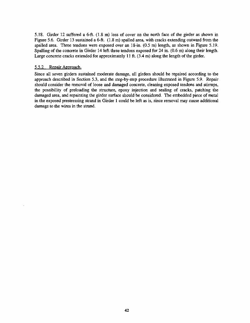
5.18. Girder 12 suffered a 6-ft. (1.8 m) loss of cover on the north face of the girder as shown in Figure 5.6. Girder 13 sustained a 6-ft. (1.8 m) spalled area, with cracks extending outward from the spalled area. Three tendons were exposed over an 18-in. (0.5 m) length, as shown in Figure 5.19. Spalling of the concrete in Girder 14 left three tendons exposed for 24 in. (0.6 m) along their length. Large concrete cracks extended for approximately 11 ft. (3.4 m) along the length of the girder.
5.5.2 Repair Approach.
Since all seven girders sustained moderate damage, all girders should be repaired according to the approach described in Section 5.3, and the step-by-step procedure illustrated in Figure 5.9. Repair should consider the removal of loose and damaged concrete, cleaning exposed tendons and stirrups, the possibility of preloading the structure, epoxy injection and sealing of cracks, patching the damaged area, and repainting the girder surface should be considered. The embedded piece of metal in the exposed prestressing strand in Girder 1 could be left as is, since removal may cause additional damage to the wires in the strand.
42

Figure 5- 18 Girder 11 - College Station bridge (Courtesy of the Texas Department of Transportation)
Figure 5- 19 Girder 13 - College Station bridge (Courtesy of the Texas Department of Transportation)
43

CHAPTER6
SUMMARY, CONCLUSIONS, AND RECOMMENDATIONS
6.1 SUMMARY
Repair of impact-damaged prestressed bridge girders remains a difficult design and construction problem. It is difficult to assess the condition of a damaged girder and to confidently design a repair scheme which will perform well for the intended service life of the bridge. The scope of this report included a survey of current repair practice in the United States and Canada, impact and remedial procedures in the 24 districts in the Texas Department of Transportation (TxDOn, and a discussion of approaches for the repair of impact damaged prestressed bridge girders as a function of severity of damage.
A survey distributed to all Texas DOT districts revealed that 241 girders were damaged in the state between 1987 and 1992, or an average of about one girder each week. This statistic justifies the need for a better understanding of impact damage, and the development of effective damage assessment and repair procedures.
The approach suggested for the repair of impact-damaged girders includes damage assessment and a discussion of repair techniques for strength, durability, and aesthetic restoration. The process was developed using data from the field study being conducted as part of the research project.
6.2 CONCLUSIONS
An average of approximately one girder per week is damaged in Texas as a result of overheight impact loads. Texas uses prestressed girders to a much greater extent than most other states and accounts for one fifth of all surveyed damage in the United States and Canada. Only 40 percent of damage incidents in Texas were recorded by means of a damage report, and very few cases are recorded within BRINSAP, the Texas Department of Transportation Bridge Inventory, Inspection, and Appraisal Program. Analytical studies were used to assess impact damage in only 4 percent of incidents in Texas. Non-destructive test methods were used in only 10% of the cases of impact damage. Most were examined visually only.
In Texas, minor damage is routinely ignored, moderate damage is patched, and severely damaged girders are typically replaced. Repair of impact damage involves one or more issues related to structural integrity, durability, and aesthetic restoration. The complexity of the repair is a function of the severity of the impact damage. Repair of both the concrete and the prestressing strands may have to be considered.
6.3 RECOMMENDA710NS
The work performed to date substantiates the need for more thorough research on repairs to impactdamaged prestressed concrete girders. Experiments involving concrete and strand repairs should be executed to evaluate the effectiveness of different repair procedures. A field testing program should be implemented to determine the long-term performance of repaired girders. An analysis procedure
45
should be developed to evaluate the degree of damage to girders and to assess the strength and performance of a bridge containing damaged or repaired elements.
A detailed report should be written for each case of impact damage. This report should include: repair materials used, the contractor perfonning the repair, photos of the damaged girder before and after the repair, equipment used for the repair, the techniques used for repair, the cost of the repair, the limitation of use for the bridge containing the repaired girders, and the results of long- term field monitoring, if applicable. In addition, all bridges with damaged girders should be recorded within BRINSAP. The girders damaged should be noted, and structural or non-structural repair of the girders should be indicated. This information is especially critical since bridges containing damaged and repaired elements may be selected for bridge widening at some point in the future, or may be considered when a route is selected for an overload pennit, potentially increasing the load which these repaired girders must carry.
46

APPENDIX A SURVEY FORM
Project 1370
Repair of Impact-Damaged Prestressed Bridge Girders
General Information Survey
District: Title:
Completed by: Phone:
Date: FAX:
Address:
I. Repair and/or Replacement of Damaged Precast Concrete Bridge Members
A. Plans and Specifications
Check office responsible for preparation of plans and specifications for the repair (check as many categories as
apply).
1. District Design/Bridge Engineer
2. Private Consultant
3. Maintenance Engineer
4. Bridge Division D-5 (Austin)
B. Construction
Check office/personnel used to perform actual repair (check as many categories as apply)
1. District/ Agency Personnel
2. Private Contractor
3. Other (please specify)
47

C. Determination of Repair Procedure
Rate the following factors by importance in the determination of the method of repair (Low, Moderate, or High
priority) for severely damaged girders.
1. Cost
2. Time required to make repair
3. Aesthetics
4. Interruption of service
5. Load capacity
6. Expected service life
7. Maintenance (corrosion protection, etc.)
8. Other (please specify)
II. General Information
1. Estimate the number of bridges damaged within your district over the past five years for the following degrees
of damage:
Minor Damage (concrete cracks and nicks, shallow spalls and scrapes)
(check here if you do not keep record of minor damage)
Moderate Damage (large concrete cracks and spalls; exposed, undamaged
tendons
Severe Damage (exposed and damaged tendons; loss of significant portion
of cross section; distortion of beam resulting in
misalignment)
2. Please comment on unique and/or successful repair methods that have been used within your district (continue
on back if needed).
48

3. Have your or anyone in your district published or compiled any information on the repair of impact damaged prestressed bridge girders?
YES
NO
If yes, please give the name of the person/author, the publication (if applicable), and where they may be reached.
4. Do you know of any girders that have been or are planning to be removed that we may make use of in laboratory
studies?
YES
NO
If yes, please give the location of the project and the name of the person to contact.
49

Completed by:
Date:
Address
PROJECT INFORMATION
District:
NBL#:
Location:
Type of Beam:
PROJECT 1370
Specific Project Survey
Title:
Phone:
FAX:
Person to Contact:
Phone No.:
Cause of Damage
(if known):
Number of
Damaged Beams:
I. INSPECTION AND DESIGN OF DAMAGED Precast Concrete Bridges (PCB)
A. Personnel Responsible for Inspection: (check appropriate personnel)
L District Design/Bridge Engineer
2. Private Consultant
3. Maintenance Engineer
4. Bridge Division D-5 (Austin)
5. Construction Engineer
6. Others (pleas!= identify)
B. Procedures used to determine extent of damage: (check appropriate items)
1. Visual observation only
2. Non-destructive testing equipment
3. Other (please specify)
50

C. Information included in damage report: (check appropriate items)
1. No Report
2. Photographs
3. Sketches of cracks or damage
4. Recommendations for continued or limited use
5. Recommendations for repair procedures
6. Other (please specify)
D. Analytical Procedures:
1. Please provide a brief description of the analytical procedures used to assess the damage to PCBs
(mc1ude names and/or types of software used for this purpose if applicable)
2. Who performed these analyses?
II. REPAIR OF DAMAGE DUE TO OVER-HEIGHT LOADS
Number of Girders Repaired:
A. Personnel Responsible for Determining Repair Method: (check appropriate personnel)
1. District Design/Bridge Engineer
Consultant
ction Engineer
Others (please identify)
51

B. Repair of Minor Damage: (concrete cracks and nicks, shallow spalls and scrapes). Please check all categories
that apply.
1. Do nothing
2. Repaint surface
3. Concrete patch
4. Other (please identify)
C. Repair of Moderate Damage: (large concrete cracks and spalls, exposed undamaged tendons). Please check
all categories that apply.
1. Do nothing
2. Patch with concrete or other proprietary material
3. Epoxy injection
4. Concrete removal/surface preparation before patching
5. Other (please identify)
D. Repair of Severe Damage: (exposed damaged tendons, loss of significant portion of cross section, and possible
distortion resulting in misalignment). Please check all categories that apply.
I. Repair of tendons
a. External post-tensioning (please describe)
b. Internal splices (please describe)
c. Metal sleeve splice
d. Combination splice (please describe)
e. Other (please describe)
52

2. Repair of Concrete: (check appropriate category)
a. Concrete removal/surface preparation before patching
b. Patch with concrete or other proprietary materials
c. Epoxy injection
d. Other (please describe)
3. Replace Girder
I Number of girders replaced:
4. Other (please identify
III. COST OF REPAIRIREPLACEI\.fENT
What was the actual cost of the repair/replacement?
IV. PERFORMANCE/CONSTRUCTION EVALUATION
How well did this repair procedure perform and will it be used in the future?
Please add any comments on problems or successes encountered during construction and additional maintenance required (continue on back if needed).
53

54

State:
Completed by:
Date:
Address:
APPENDIXB OUI'-OF-STATE SURVEY FORM
THE UNIVERSITY OF TEXAS AT AUSTIN Repair of Impact-Damaged Prestressed Bridge Girders
General Information Survey
Title:
Phone:
FAX:
I. Repair and/or Replacement of Damaged Precast Concrete Bridge Members
A. Plans and Specifications
Check office responsible for preparation of plans and specifications for the repair (check as many categories as apply).
1. District Design/Bridge Engineer
2. Area Engineer
3. Private Consultant
4. Maintenance Engineer
State Bridge Division
). Other (please specify)
B. Construction
Check office/personnel used to perform actual repair (check as many categories as apply}
1. District/ Agency Personnel
2. Private Contractor
3. Other (please specify)
55

C. Determination of Repair Procedure
Rate the following factors by importance in the determination of the method of repair (Low, Moderate, or High priority) for severely damaged girders.
1. Cost
2. Time required to make repair
3. Aesthetics
4. Interruption of service
5. Load capacity
6. Expected service life
7. Maintenance (corrosion protection, etc.)
8. Public safety
9. Other (please specify)
ll. Generallnfonnation
1. Estimate the number of bridges damaged within your state over the past five years for the following degrees of damage:
Minor Damage (concrete cracks and nicks, shallow spalls and scrapes) (check here if you do not keep record of minor damage)
Moderate Damage (large concrete cracks and spalls; exposed, undamaged tendons)
Severe Damage (exposed and damaged tendons; loss of significant portion of cross section; distortion of beam resulting in misalignment)
2. Please comment on unique and/or successful repair methods that have been used within your district (continue on back if needed).
56

3. Have your or anyone in your state published or compiled any information on the repair of impact-damaged prestressed bridge girders?
~ ~
If yes, please give the name of the person/author, the publication (if applicable), and where they may be reached.
57

THE UNIVERSITY OF TEXAS AT AUSTIN SPECIFIC PROJECT SURVEY
Completed by: Title:
Date: Phone:
Address:
PROJECT INFORMATION:
State: Person to Contact:
County: Phone No.:
Location: Cause of Damage (if known)
Type of Number of Beam: Damaged Beams:
Minimum vertical clearance of bridge:
Route travelling ON bridge:
Route travelling UNDER bridge:
Bridge identification number (if any)
58

I. INSPECTION AND DESIGN OF DAMAGED Precast Concrete Bridges (PCB)
A. Personnel Responsible for Inspection: (check appropriate personnel)
1. District Design/Bridge Engineer
2. Private Consultant
3. Maintenance Engineer
4. State Bridge Division
5. Construction Engineer
6. District Bridge Inspector
7. Others (please identify)
B. Procedures nsed to determine extent of damage: (check appropriate items)
1. Visual observation only
2. Non-destructive testing equipment
3. Other (please specify)
C. Information included in damage report: (check appropriate items)
1. No report
2. Photographs
3. Sketches of cracks or damage
4. Recommendations for continued or limited use
5. Recommendation for repair procedures
6. Follow-Up Action
7. Other (please specify)
D. Analytical Procedures:
1. Please provide a brief description of the analytical procedures used to assess the damage to PCBs (include names and/or types of software used for this purpose, if applicable)
2. Who performed these analyses?
59

IT. REPAIR OF DAMAGE DUE TO OVER-HEIGIIT LOADS
I Number of Girders Repaired:
A. Personnel Responsible for Determining Repair Method: (check appropriate personnel)
1. District Design/Bridge Engineer
2. Private Consultant
3. Maintenance Engineer
4. State Bridge Division
5. Construction Engineer
6. Others (please identify)
B. Repair of Minor Damage: (concrete cracks and nicks, shallow spalls and scrapes) Please check all categories that apply.
1. Do nothing
2. Repaint swface
3. Concrete patch
4. Other (please identify)
C. Repair of Moderate Damage: (large concrete cracks and spalls, exposed undamaged tendons) Please check all categories that apply.
1. Do nothing
2. Patch with concrete or other proprietary materials
3. Epoxy injection
4. Concrete removal/surface preparation before patching
5. Clean tendons
6. Other (please identify)
60

D. Repair of Severe Damage: (exposed damaged tendons, loss of significant portion of cross section, and possible distortion resulting in misalignment) Please check all categories that apply.
1. Repair of tendons:
a. External post-tensioning (please describe)
b. Internal splices (please describe)
c. Metal sleeve splice
d. Combination splice (please describe)
e. Other (please describe)
2. Repair of concrete: (check appropriate category)
a. Concrete removal/surface preparation before patching
b. Patch with concrete or other proprietary materials
c. Epoxy injection
d. Others (please describe)
3. Replace girder:
I Number of girders replaced
4. Other: (please identify)
61

m. COST OF REPAIRJREPLACEMENI'
What was the actual cost of the repair/replacement?
IV. PERFORMANCE/CONSTRUCTION EVALUATION
How well did this repair procedure perform and will it be used in the future?
Please add any comments on problems or successes encountered during construction and additional maintenance required (continue on back if needed)
One objective of this survey is to locate repair projects that are or will be underway shortly. If you have or anticipate any repair-in-place projects that may be of interest to us, please list them in the space provided below.
62

APPENDIXC PARTICIPATING STATES AND PROVINCES
United States: Delaware Kentucky North Dakota
Alabama Florida Louisiana Ohio
Alaska Georgia Minnesota Oklahoma
Arizona Hawaii Missouri Vermont
Arkansas Idaho Montana Washington
California Indiana Nebraska West Virginia
Colorado Iowa Nevada Wyoming
Connecticut Kansas New York
Canada: New Brunswick Nova Scotia Saskatchewan
Alberta Newfoundland Ontario
Manitoba
63

64

REFERENCES
1. ACI Committee 207. "Practices for Evaluation of Concrete in Existing Massive Structures for Service Conditions." Concrete International: Design and Construction, Vol. 1, No. 3, March 1979, pp. 48-61.
2. ACI Committee 224. "Causes, Evaluation, and Repair of Cracks in Concrete Structures." Journal of the American Concrete Institute, Vol. 81, No. 3, May-June 1984, pp. 211-230.
3. ACI Committee 345. "Routine Maintenance of Concrete Bridges." ACI SCM-8(85}, pp. 25-46.
4. ACI Committee 546. "Guide for Repair of Concrete Bridge Superstructures." Concrete International: Design and Construction, Vol. 2, No. 9, Sept. 1980, pp.69-88.
5. Andrews, G., and Shanna, A.K. "Repaired Reinforced Concrete Beams." Concrete International: DesignandConstruction, Vol. 10, No. 4, April1988, pp. 47-51.
6. ASTM. Standardization Basics, Philadelphia: American Society for Testing of Materials.
7. ATU. Restressing Broken Strand, Alberta Transportation and Utilities, unpublished.
8. ATU. Alberta Department of Transportation Bridge Services B380 - April 86 Specification: Repair of Prestressed Concrete Bridge Girders Damaged By High Load Impact, Alberta Transportation and Utilities, unpublished.
9. ATU. Specification for the Supply of Concrete Patching Material, Alberta Transportation and Utilities, unpublished.
10. Bullock, RE. "Factors Intluencing Concrete Repair Materials." Concrete International: Design and Construction, Vol. 2, No. 9, Sept. 1980, pp. 67-68.
11. Chou, G.K. "Cathodic Protection: A Solution to Rebar Corrosion." A CI SCM-13{86), pp. 125-135.
12. Ellyin, F., and Matta, R.A. "Bonding and Corrosion Protection Properties of Two Coatings for Prestressing Steels." Journal of the American Concrete Institute, Vol. 79, No.5, Sept.-Oct. 1982, pp. 366-371.
13. Emmons, P.H. Concrete Repair and Maintenance Illustrated, United States: R.S. Means Company, Inc., 1993.
65

14. Gaul, R. W. "Surface Preparation of Concrete for Paints and Coatings." Concrete Construction, Vol. 26, No. 5, May 1981, pp. 401-405.
15. Greve, H. G. "Restoring Strength to Damaged or Deteriorated Structural Concrete." Concrete Constroction, Vol. 32, No. 11, Nov. 1987, pp. 949-957.
16. HBT AGRA Limited. Evaluation of Length Change of Concrete Patching Materials to Alberta Transportation and Utilities Specification B-39 1, unpublished.
17. INCO. Co"osion inAction, 6th. ed. New York: The International Nickel Company, Inc., 1977.
18. Kaminetzky, D. "Verification of Structural Adequacy." ACI SCM-8{85), pp. 101-115.
19. Kline, T. "Crack Repair: An Engineer's Perspective." Concrete International: Design and Construction, Vol. 13, No. 6., June 1991, pp. 47-49.
20. · Kopt: RJ., Cooper, C.G., and Williams, F.W. "In-Situ Strength Evaluation of Concrete Case Histories and Laboratory Investigations." Concrete International: Design and Construction, Vol. 3, No. 3, March 1981, pp.66-71.
21. Lankard, D.R, Clear, KC., and Schull, T. "Cathodic Protection for Overhead Construction." Concrete Construction, VoL 32, No. 2, Feb. 1987, pp. 193-195.
22. Lin, T.Y., and Bums, N.H. Design of Prestressed Concrete Structures, 3rd ed, United States: John Wiley and Sons, 1981.
23. McGovern, M.S. "Cementitious Patching Materials." Concrete Repair Digest, VoL 2 No.5, Oct.-Nov. 1991, pp. 139-142.
24. McGovern, M.S. "Evaluating Patching Materials." Concrete Repair Digest, Vol. 2 No. 5, Oct.-Nov. 1991, pp. 143-145.
25. Mailvaganam, N.P., and Deans, J.J. "Patching and Resurfacing Materials." Repair and Protection of Concrete Structures, United States: CRC Press, 1992, pp. 43-86.
26. Mailvaganarn, N.P., Deans, J.J., and Cleary, K. "Substrate Preparation." Repair and Protection of Concrete Structures, United States: CRC Press, 1992, pp. 231-240.
27. Mailvaganam, N.P., and Deans, J.J. "Patching and Resurfacing." Repair and Protection of Concrete Structures, United States: CRC Press, 1992, pp. 241-254.
28. Mailvaganarn, N.P., and Deans, J.J. "Repair of Cracks." Repair and Protection of Concrete Structures, United States: CR~tr~ss, 1992, pp. 287-303.

29. Mansur, M.A., and Ong, K.C.G. "Epoxy-Repaired Beams." Concrete International: Design and Construction, Vol. 7, No. 10, October 1985, pp. 46-50.
30. Mays, G., and Wilkinson, W. "Polymer Repairs to Concrete: Their Influence on Structural Performance." ACI SCM -21(89), pp. 477-489.
31. Mendis, P. "Commercial Applications and Property Requirements for Epoxies in Construction." ACI SCM-21(89), pp. 391-397.
32. Mindess, S., and Young, F.J. Concrete, Englewood Cliffs: Prentice Hall, Inc., 1981.
33. Murray, M.A. "Epoxy Injection Welds Cracks Back Together. 11 Concrete Construction, Vol. 32, No. 1, Jan. 1987, pp. 45-49.
34. Neville, AM. "Properties of Concrete - An Overview, Part 1 of 3." Concrete International: Design and Construction, Vol. 8, No. 2, Feb. 1986, pp. 20-23.
35. Neville, AM. "Properties of Concrete - An Overview, Part 2 of 3." Concrete International: Design and Construction, Vol. 8, No. 3, March 1986, pp. 60-63.
36. Neville, AM. "Properties of Concrete - An Overview, Part 3 of 3." Concrete International: Design and Construction, Vol. 8, No. 4, April1986, pp. 53-57.
37. Palmer, R.A "Emergency Bridge Repair in Minnesota." Journal of the Prestressed Concrete Institute, Vol. 19, No 1, Jan.-Feb. 1974, pp. 73-75.
38. Pfeifer, D.W., and Perencllio, W.F. "Sealers or Overlays?" Concrete Construction, Vol. 29, No. 5, May 1984, pp. 503-507.
39. Pickard, S.S. "Concrete Repair and Restoration: Anticipating a Growing Market for the 80's." Concrete International.· Design and Construction, Vol. 2, No. 9, Sept. 1980, pp. 22-26.
40. Reading, T.J. "Durability of Shotcrete." Concrete International: Design and Construction, Vol. 3, No. 1, Jan. 1981, pp. 27-33.
41. Reading, T.J. "Shotcrete for Building Repairs." Concrete Construction, Vol. 26, No. 5, May 1981, pp. 379-383.
42. Schrader, E.K. "Mistakes, Misconceptions, and Controversial Issues Concerning Concrete and Concrete Repairs, Part 1 of 3." Concrete International: Design and Construction, VoL 14, No. 9, Sept. 1992, pp. 52-56.
67

43. Schrader, E.K. "Mistakes, Misconceptions, and Controversial Issues Concerning Concrete and Concrete Repairs, Part 2 of 3." Concrete International: Design and Constroction, Vol. 14, No. 10, Oct. 1992, pp. 48-52.
44. Schrader, E.K. "Mistakes, Misconceptions, and Controversial Issues Concerning Concrete and Concrete Repairs, Part 3 of 3." Concrete International: Design and Constroction, Vol. 14, No. 11, Nov. 1992, pp. 54-59.
45. Schupack, M. "Divorces and Ruptured Relations Between Epoxies and Concrete." Concrete Constroction, VoL 25, No. 10, Oct. 1980, pp. 735-738.
46. Schutz, R.J. "Getting Ready for Concrete Repairs." Concrete Constroction, Vol. 26, No. 5, May 1981, pp. 391-393.
47. Shanafelt, G.O., and Horn, W.B. "Damage Evaluation and Repair Methods for Prestressed Concrete Bridge Members. 11 National Co-operative Highway Research Program Report 226, Washington, D.C.: National Research Council, Nov. 1980.
48. Shanafelt, G.O:, and Horn, W.B. "Guidelines for Evaluation and Repair of Prestressed Concrete Bridge Members." National Co-operative Highway Research Program Report 280, Washington, D.C.: National Research Council, Dec., 1985.
49. unknown. "Epoxies for Concrete Repair and Restoration." Concrete Construction, Vol. 24, No. 3, March 1979, pp. 169-174.
50. unknown. "Patching Concrete With Rapid-Setting Materials." Concrete Construction, Vol24, No. 3, March 1979, pp. 177-180.
51. unknown. "Hi-Performance Patching System Remedies Damaged Concrete. II Concrete International: Design and Construction, Vol. 2, No. 9, Sept. 1980, pp. 132-134.
52. unknown. "Three Steps to Correct Surface Defects." Concrete Construction, Vol. 25, No. 3, March 1980, pp. 215-219.
53. unknown. "IdentifYing Concrete Deterioration." Concrete Construction, Vol. 26, No. 1, Jan. 1981, pp. 14-18.
54. unknown. "A Guide to Repair of Concrete." Concrete Construction, Vol. 22, No. 3, March 1977, pp. 123-174.
55. unknown. "The Repairability of Concrete." Concrete Construction, Vol. 25, No. 1, Jan. 1980, pp. 41-44.
68

56. unknown. "Secrets ofLasting Repairs." Concrete Construction, Vol. 26, No. 1, Jan. 1981, p. 19.
57. unknown. "Basic Concrete Repair: Don't Undertake Repairs Without Understanding TheseRequirements." Concrete Construction, Vol. 26, No. 1, Jan. 1981, pp. 21-23.
58. unknown. "Repair Techniques and Materials: A Guide to the Selection of the Right Methods and Materials for the Job." Concrete Constroction, VoL 26, No. 1, Jan. 1981, pp. 31-47.
59. unknown. "Patching Concrete With Rapid-Setting Materials: A Guide to Their Choice and Use." Concrete Construction, Vol. 24, No. 3, March 1979, pp. 177-180.
60. unknown. "How to Fix Cracks." Concrete Construction, VoL 30, No. 1, Jan. 1985, pp. 37-44.
61. unknown. "Latex-Modified Concrete and Mortar for Repair." Concrete Construction, Vol. 29, No. 10, Oct. 1984, pp. 889-892.
62. unknown. "Concrete Repair and Rehabilitation." Concrete International: Design and Construction, VoL 6, No.7, July 1984, pp. 47-49.
63. unknown. "Epoxy Penetration." Concrete International: Design and Construction, VoL 8, No. 2, Feb. 1986, pp. 46-50.
64. Waddell, ll "Basic Steps of a Concrete Repair Program." Concrete International: Design and Construction, Vol. 2, No. 9, Sept. 1980, pp. 30-33.
65. Warner, J. "Selecting Repair Materials: Some Important Material Properties that Should be Considered." Concrete Construction, Vol. 29, No. 10, Oct. 1984, pp. 865-871.
66. Wmand, A, Paduart, A, and Dubois, P.M. "Reparation d'un Pont Ferroviaire en Beton Precontraint a Trois Travees Continues." IABSEProceedings P-27180, IABSE Periodica ll1980, Zurich: International Association for Bridge and Structural Engineers, February 1980.
69