Embed Size (px)
Citation preview

Current BG Status at Belle
Osamu Tajima
( Tohoku univ )
Assumption in this talk 100days-operation / yr 1nTorr CO pressure in simulation HER / LER = 1.1 / 1.6 A in simulation

Contents
• Design concepts for BG reduction
• BG measurements
Radiation dose
Hit rate (SVD occupancy)
Layer (radius) dependence
• Comparison data and simulation
Support Super-KEKB / Belle design
• Ideas for Less BG

SVD Upgrade in 2003 summer
rbp = 2.0 cm 3 layers Rad. hardness
rbp = 1.5 cm 4 layers > 10 MRad (DSSD) > 20 MRad (reado
ut chip)
~ 1 MRad
Better vertex resolution / tracking efficiency

SVD Upgrade for Super-Belle
rbp = 1.5 cm
Super-Belle• Smaller rbp (1cm)• Higher beam current• Basic design is same as SVD2 beampipe
• We must understand Current Situation• Success of beampipe design is key-point
for Super-KEKB/Belle

Beam-BG on Belle-SVD2
Synchrotron Radiation (SR)
Particle Background
Showers from scattered beam particles by Residual Gas or intra-beam scattering
Soft-SR (several keV)
Hard-SR ( keV ~ 150 keV)
Generated by upstream magnets
Backscattering from downstream
Brem. Coulomb Touschek

Reduction of Particle-BG
Particle BG ~ 70 kRad/yr

Reduction of Soft-SR
Au-coating !
crescent shapeSR-mask
some efforts

Reduction of Soft-SR
Au-coating !
crescent shapeSR-mask
Au coating absorbs low energy photon less than 8 keV

Reduction of Soft-SR
Au-coating !
crescent shapeSR-mask
Saw-tooth surface shape in Ta blind Soft-SR reflected on Ta

Reduction of Soft-SR
Au-coating !
crescent shapeSR-mask (~2.5mm)
Crescent shape SR-mask blind Be section from Soft-SR

Reduction of Soft-SR
Au-coating !
crescent shapeSR-mask
Soft-SR ~ few kRad/yr

Reduction of Hard-SR
Scattered at downstream photon-stop (OC2RE chamber)
HER e-
High energy SRis generated inOCS magnet
•Put photon-stop far place (~9m)•Chamber material: Cu
Hard-SR ~ 29 kRad/yr
Beam-BG on Belle-SVD2
Synchrotron Radiation (SR)
Particle Background
Showers from scattered beam particles by Residual Gas or intra-beam scattering
Soft-SR (several keV)
Hard-SR ( keV ~ 150 keV)
~ 70 kRad/yr @ 1st layer
few kRad/yr @ 1st layer
~ 29 kRad/yr
Generated by upstream magnets
Backscattering from downstream
Brem. Coulomb Touschek
BG measurement and Comparison with simulation

SR measurement w/ Single-Bunch HER 15 mA, with adjusting trigger timingCan measure dose w/ hit-rate (0.2 % occupancy) and energy deposition (15 keV/ch) ~20 kRad/yr dose @ 1.1 A (33 kRad/yr at max. position, =180deg) ( contribution below th. is corrected by simulation)
SVD 2.0 SVD 1.Xdatasimulation

SVD Cluster Energy Spectra in Single Beam Run
HER 0.8 A LER 1.5 A
Can extract SR from spectrum shape !?
Only Particle-BG
SR and Particle-BG

E-spectrum of HER Particle-BG
energy (keV)
#clu
ster
s/ke
V/e
vent • Diff. btw vacuum
bump on/off in HER• LER 1.5 A
HER E-spectrum of particle BG issame as LER !!
Can measure SRand particle-BG
separately

Extraction SR in HER Single Beam
50 mA 100 mA 200 mA
400 mA 600 mA 800 mA
HERParticle
SR
Hard-SR simulation
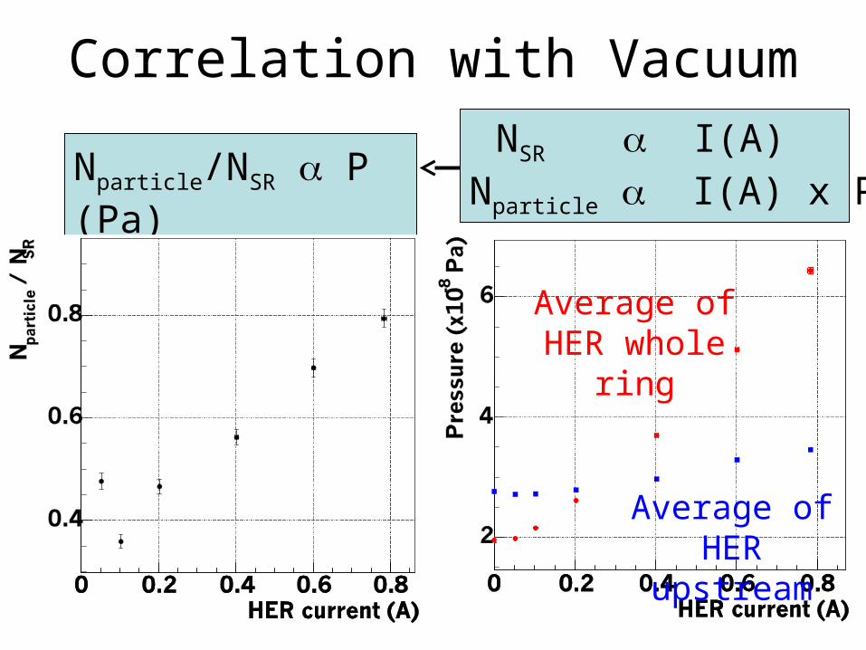
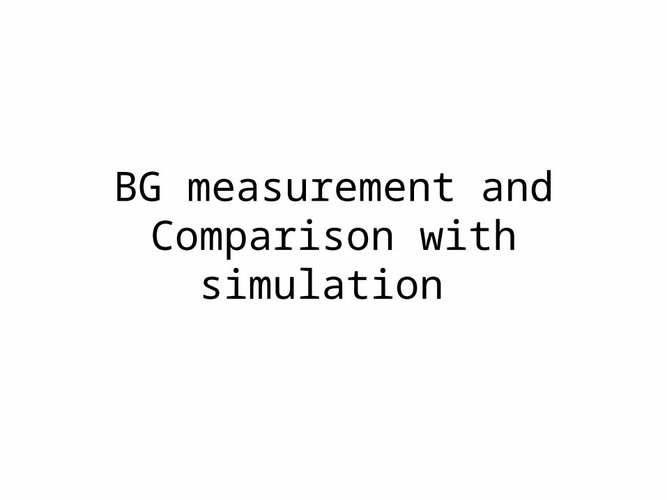
Correlation with Vacuum
Nparticle/NSR P(Pa) NSR I(A)Nparticle I(A) x P(Pa)
Average of HER whole ring
Average of HER upstream

Azimuthal Distribution of SR
33 kRad/yrat HER 1.1A
21 kRad/yrat HER 1.1A
Only above threshold 10 keVSimulation complements below thereshold
simulation
29 kRad/yr
Single-Bunch 15 mA (trigger-timing is adjusted)Total 0.8 A w/ 1284 bunch (random timing)Hard-SR simulation

Azimuthal Distribution of Particle BG
44 kRad/yrat HER 1.1A
43 kRad/yrat LER 1.6A
HER 0.8 A
LER 1.5 A
simulation
53 kRad/yr
simulation
21 kRad/yr

Study of Touschek EffectTouschek contribution < 20 % at collision ~ 50 % at single beam 31 % in simulation
Smaller beam-size (larger density)
larger background
If no Touschek
Touschek contributionmust be corrected
Collision run
Single beam run

Azimuthal Distribution of Particle BG
44 kRad/yrat HER 1.1A
43 kRad/yrat LER 1.6A
HER 0.8 A
LER 1.5 A
simulation
53 kRad/yr
simulation
21 kRad/yr
22
18

Radiation Dose at SVD 1st layerAt Maximum Currents: HER 1.1A, LER 1.6A
Outer-direction
~ 0 degree
Inner-direction
~ 180 degree
Particle-BG (LER) 22 (18) kRad/yr 14 (11) kRad/yr
Particle-BG (HER) 44 (53) kRad/yr 29 (33) kRad/yr
SR-BG 17 (8) kRad/yr 33 (29) kRad/yr
Total 83 (79) kRad/yr 76 (73) kRad/yr
(…) is simulation @ 1nTorr pressure
Data and simulation is consistentTouschek contribution is reduced based on measurement
• Two parameters have large uncertainty (pressure, movable mask)• It may happen that absolute values too well agree• Consistency of azimuthal distribution is important

Radiation Dose at SVD 1st layerAt Maximum Currents: HER 1.1A, LER 1.6A
Outer-direction
~ 0 degree
Inner-direction
~ 180 degree
Particle-BG (LER) 22 (18) kRad/yr 14 (11) kRad/yr
Particle-BG (HER) 44 (53) kRad/yr 29 (33) kRad/yr
SR-BG 17 (8) kRad/yr 33 (29) kRad/yr
Total 83 (79) kRad/yr 76 (73) kRad/yr
(…) is simulation @ 1nTorr pressure
Data and simulation is consistentTouschek contribution is reduced based on measurement• We can trust simulations
• Its uncertainty for abs. may be factor a few

Constraint for Occupancy (hit-rate)
At Maximum Currents (HER 1.1A, LER 1.6A)
Outer-direction
~ 0 degree
Inner-direction
~ 180 degree
Particle-BG (LER) 3 % 2 %
Particle-BG (HER) 7 % 5 %
SR-BG 2 % 4 %
Total (single beam) 12 % 11 %
Radiation Dose Occupancy (cluster size: Particle-BG 3.5 ch, SR 1.5 ch)
Collision 12 % 11 %

Energy spectra for each layers
LERsingle beam
1str ~ 2cm
2ndr ~ 4.4cm
3rdr ~ 7cm
4thr ~ 8.8cm
HERsingle beam

Layer dependence (single beam)Particle (LER) Particle (HER) SR
BG 1/(r-rbp), rbp: beampipe radius
There may be correlation BG and 1/(r-rbp)
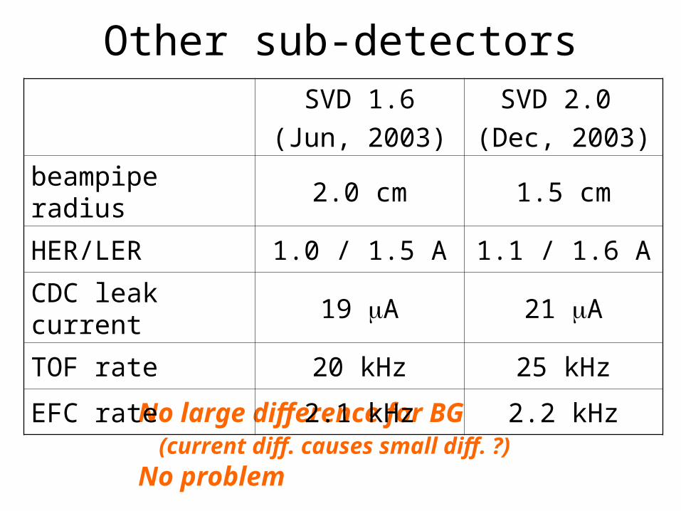
Other sub-detectors
No large difference for BG (current diff. causes small diff. ?)
No problem
SVD 1.6
(Jun, 2003)
SVD 2.0
(Dec, 2003)
beampipe radius 2.0 cm 1.5 cm
HER/LER 1.0 / 1.5 A 1.1 / 1.6 A
CDC leak current 19 A 21 A
TOF rate 20 kHz 25 kHz
EFC rate 2.1 kHz 2.2 kHz
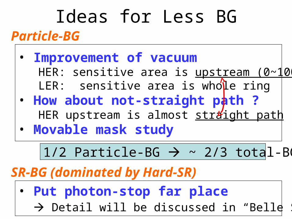
Ideas for Less BG
• Improvement of vacuum HER: sensitive area is upstream (0~100 m) LER: sensitive area is whole ring• How about not-straight path ? HER upstream is almost straight path• Movable mask study
Particle-BG
1/2 Particle-BG ~ 2/3 total-BG/Occ.
• Put photon-stop far place Detail will be discussed in “Belle SR” talk
SR-BG (dominated by Hard-SR)

Summary• Beampipe radius 2 1.5 cm ( 1 cm)
• Dose level is smaller (100 80 kRad/yr) Consistent with simulation
• Measure SR & Particle-BG separately using energy spectrum of SVD SR contribution ~1/3 of total
• Touschek is low < 20 % of LER-BG
• BG may decrease 1/(r-rbp)
Success of beampipe design Strong support for design in Super-B
Super-B
This method is first time in the world !?

####### backup #######

Radiation Monitors
18 kRad/yr
80 kRad/yr60 kRad/yr
before 100 kRad/yr
Dose on Si is consistent with monitor

Is monitors measuring SR ?
Be pipe
Outer-side of ring
Inner-side of ringThe 300 m Au on the manifold blinds SR-BG
Backscattered Hard-SR
BWD FWD
Most of SR photons are absorbed by Au, and converted to lower energy photons (8~14keV) via the photoelectric effect
e-
Difficulty to measure SRDose at DSSD center is same ?
Measure BGby DSSD itself

Very Rough Estimation of Dose
We can measure dose using its energy deposition - Occupancy ~ 10 % - Energy Deposition ~ 46 keV/ch - Bunch cycle 10 usec - Shaping time 2.6~3.0 usec
~100 kRad/yr - No subtraction of electrical noise, bad-ch effect - Contribution below threshold (~15keV) is not considered - Need to consider below th. for SR (low energy should be dominated by SR)
Must measure for each components

SVD Hit Occupancy (hit-rate)
• 1st layer (R=2 cm) 10~12 % (HER 1.1A, LER 1.6A)
• Before (R=2.5 cm) 7 ~ 8 % (HER 1.0A, LER 1.5A)• 2nd layer (4.3 cm) ~ 4 %, 3rd, 4th layer ~ 2 %

SVD Occupancy (hit-rate)
SVD 1.6SVD 2.0
beampipe radius
Large diff. of occ. btw 1st – 2nd layersmay come from 1/(r-rbp) relation

Single Bunch like RunHER 15 mA, with adjusting trigger timingSVD 1st layer occupancy ~ 0.2 % corresponds to ~ 4 % occupancy @ 1.1 AEnergy deposition 15.2 keV/ch corresponds to ~20 kRad/yr dose @ 1.1 A (33 kRad/yr at maximum position, =180deg) ( contribution below th. is corrected by simulation)
SVD 2.0 SVD 1.Xdatasimulation

Correlation with Vacuum
Average Pressure
(Nparticle/NSR) / P(Pa) = const
Upstream Pressure

Background at Collision
71 kRad/yr
11 kRad/yr
Total doseParticle-BGSR-BG
Run1560 (threshold ~15 keV) HER : 1.1 A, LER : 1.6 A
Consistent with expectation from single-beams

Study of Touschek (life-time)
1.4A1.1A
Touschek contribution < 20 % at collision ~ 45 % at single beam 42 % in simulation
Smaller beam-size (density)
shorter life-time and larger background
If no Touschek
Single beam run
Touschek contributionmust be corrected
1/ beam-density
Collision run
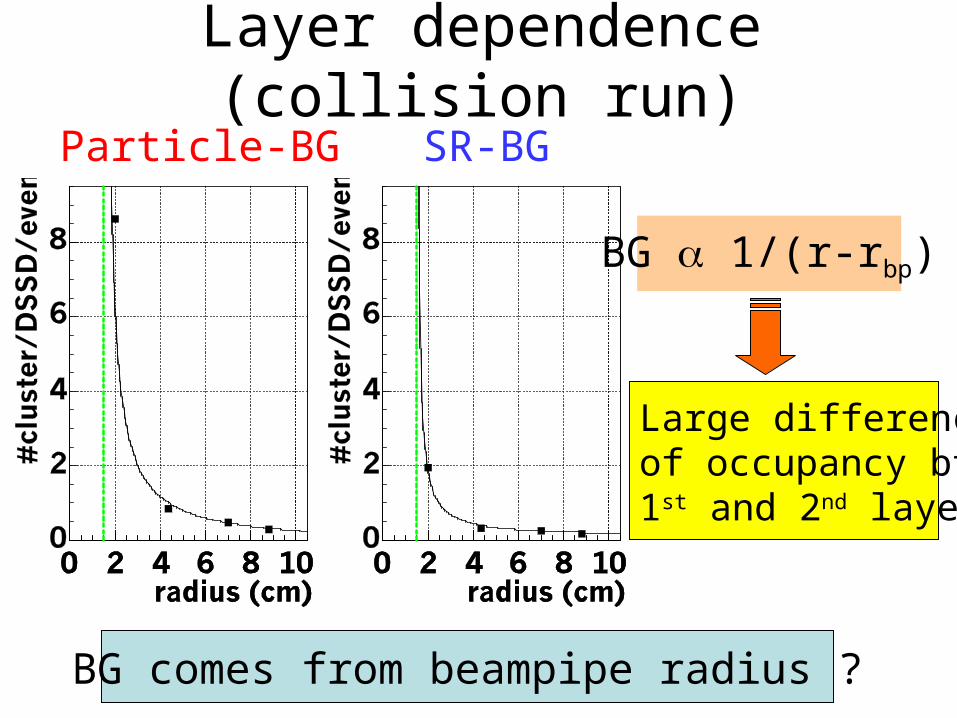
Layer dependence (collision run)Particle-BG SR-BG
BG 1/(r-rbp)
BG comes from beampipe radius ?
Large differenceof occupancy btw1st and 2nd layer

Is there reasonable reason to explain 1/(r-rbp) correlation?
Be pipe
SR is scattered / absorbed at Au coating
Backscattered Hard-SRe-
Spent particles are scattered thin-Ta region Large contribution comes from here (simulation)
Ta TaBe pipe