Embed Size (px)
DESCRIPTION
CT and PT basics
Citation preview

Power Transmission and Distribution
Author
Page 241 2007-08Copyright © Siemens AG 2007. All rights reserved.
PTD SE PTIAuthor
Basics of Current and Voltage Transformers

Power Transmission and Distribution
Author
Page 242 2007-08Copyright © Siemens AG 2007. All rights reserved.
PTD SE PTIAuthor
2
112 N
N ⋅=′ IIR1jX1 jX2 R2I1 I2
Zb
S2P2Ideal CT
S1P1 Im
N1 N2 ZmU2
Equivalent current transformer circuit
X1 = Primary leakage reactanceR1 = Primary winding resistanceX2 = Secondary leakage reactanceZ0 = Magnetizing impedanceR2 = Secondary winding resistanceZb = Secondary load
Note: Normally the leakage fluxes X1 and X2 can be neglected

Power Transmission and Distribution
Author
Page 243 2007-08Copyright © Siemens AG 2007. All rights reserved.
PTD SE PTIAuthor
jX2
i2 ZBi1
1 : N2
R2
RB
i'1 = ⋅ i1 i21N2
LW
L2<< LW
R2
im
Current transformer, simplified equivalent circuit

Power Transmission and Distribution
Author
Page 244 2007-08Copyright © Siemens AG 2007. All rights reserved.
PTD SE PTIAuthor
N1
I1
I2
N2
Zb
I2
δ
ε
I1
Im
. N1N2
Current transformer:Phase displacement (δ) and current ratio error (ε)

Power Transmission and Distribution
Author
Page 245 2007-08Copyright © Siemens AG 2007. All rights reserved.
PTD SE PTIAuthor
CT classes to IEC 60044-1: 5P or 10P
Specification: 300/1 A 5P10, 30 VA
5% accuracyat I= n x In Accuracy limit factor ALF
Rated burden (nominal power) PNB
Ratio In -Prim / In -Sek.
BBPiPNBPiPALFALF
++
×='Actual accuracy limit factor in operation is higher as the CTis normally underburdened :
Operating ALF: ALF‘
Dimension criterium:
TFKnI
SCIALF ×−≥ max'
KTF (over-dimensioning factor) considers the single sided CT over-magnetising due to the d.c. component in short circuit current ISC.KTF values required in practice depend on relay type and design.Recommendations are provided by manufacturers (see Application Guides)
RCT ≤ 5 Ohm
CT2
.seci RIP ×=

Power Transmission and Distribution
Author
Page 246 2007-08Copyright © Siemens AG 2007. All rights reserved.
PTD SE PTIAuthor
UKN
10 %
50 %
U2
Im
Definition of the CT knee-point voltage
IEC 60044-1 Class PX
formerly
British Standard BS3938: Class X

Power Transmission and Distribution
Author
Page 247 2007-08Copyright © Siemens AG 2007. All rights reserved.
PTD SE PTIAuthor
Accuracy classCurrent errorat nominal current (In)
Angle error δat rated current
In
Total error at n x In(rated accuracy limit)
5P
10P
± 1 %
± 5%
± 60 minutes 5 %
10 %
IEC 60044-1 specifies the following classes:
Current transformer, Standard for steady-state performance

Power Transmission and Distribution
Author
Page 248 2007-08Copyright © Siemens AG 2007. All rights reserved.
PTD SE PTIAuthor
Current transformers, Standard for transient performance
IEC 60044-6 specifies four classes:
Class
Ratio error Angle error
Maximum error atrated accuracy limit
TPX(closed iron core)
TPYwith anti-remanence
air gap
TPZlinear core
± 30 min
± 30 min
± 180 ± 18 min
± 0,5 %
± 1,0 %
± 1,0 %
%10ˆ ≤ε
only)current (a.c.%10ˆ ≤ε
%10ˆ ≤ε
Error at rated current
TPSclosed iron core
Special version for high impedance protection(Knee point voltage, internal secondary resistance)
Remanence
no limit
< 10 %
negligible
No limit

Power Transmission and Distribution
Author
Page 249 2007-08Copyright © Siemens AG 2007. All rights reserved.
PTD SE PTIAuthor
Current transformer saturation
Steady-state saturation with AC current
Transient saturation with offset current

Power Transmission and Distribution
Author
Page 250 2007-08Copyright © Siemens AG 2007. All rights reserved.
PTD SE PTIAuthor
Φ
ΦS
ISC
Im
DC flux non-saturated
AC flux
Magnetising current
Short circuit current
Transient CT saturation due to DC component

Power Transmission and Distribution
Author
Page 251 2007-08Copyright © Siemens AG 2007. All rights reserved.
PTD SE PTIAuthor
ΙP primary current
TN
Btotal flux
a.c. flux
transient d.c. flux
BMax
B~
t
t
d.c. component
B~
)(ω1 TSt
TNt
SN
SN
~
−−−
−⋅⋅
+= eeTTTT
BBˆ
TNTSTS
S
NS
Max ω1~
−⎜⎜⎝
⎛⎟⎠⎞⋅⋅+=
TTT
BB
N
S
NS
SN
Max B nTTl
TTTTt ⋅
−=
⋅
δtanω1
Bi
W
S ⋅=
+=
RRLT
[ ]
[ ] ms10900min
S δ=TFor 50 Hz:
Course of CT-flux during off-set short-circuit current

Power Transmission and Distribution
Author
Page 252 2007-08Copyright © Siemens AG 2007. All rights reserved.
PTD SE PTIAuthor
CT transient over-dimensioning factor KTF
KTF
TS [ms]
50 100 150 200
10
20
30
40
50
60
100
250
500
1000
5000
∞ (KTF ≈1+ωTN)
Closed iron core
Linear core
TN = network time constant(short-circuit time constant)
TS = CT secondary time constantTN [ms]
NS
S
TTT
S
NSTF ω1
−
⎜⎜⎝
⎛⎟⎟⎠
⎞+= TTTK

Power Transmission and Distribution
Author
Page 253 2007-08Copyright © Siemens AG 2007. All rights reserved.
PTD SE PTIAuthorTp
⎟⎟⎟⎟
⎠
⎞
⎜⎜⎜⎜
⎝
⎛
⋅+= N
M
TFTt-
e - 1 N1 TK' ω
N
NNTF 11
RXTK +=+= ω
0 20 40 60 80 100
5
10
15
40 ms
50 ms
30 ms
10 ms
20 ms
tM
K‘td
[ ms]
∞→Mt
14
6
CT with closed iron core,Over-dimensioning factor KTF‘ for specified time to saturation (tM)
:tM ∞→

Power Transmission and Distribution
Author
Page 254 2007-08Copyright © Siemens AG 2007. All rights reserved.
PTD SE PTIAuthor
0 20 40 60 80 1000
20
40
60
80
100
120
140
160
180
0 20 40 60 80 1000
0.5
1
1.5
2
2.5
3
3.5
4KTF
TN in ms
10 ms
8 ms
6 ms
4 ms
2 ms
2 ms
6 ms4 ms
8 ms10 ms
tM
tM Θ (tM,TN)
(el. degree)
CT over-dimensioning factor KTF (tM,TN) in the case of short time to saturation (tM)
TN in ms

Power Transmission and Distribution
Author
Page 255 2007-08Copyright © Siemens AG 2007. All rights reserved.
PTD SE PTIAuthor
Current transformermagnetising and de-magnetising
ΙP
B BMax
Ιm
BR
t Ιm
BMax
BR
B
t
( ) TSt
RMax.R
−⋅−+= eBBBB

Power Transmission and Distribution
Author
Page 256 2007-08Copyright © Siemens AG 2007. All rights reserved.
PTD SE PTIAuthor
Current transformerCourse of flux in the case of non-successful auto-reclosure
tF1 tDT tF2
tF1 = duration of 1st fault
tDT dead time
tF2 =duration of 2nd fault
B
t
Bmax
⎥⎥⎥
⎦
⎤
⎢⎢⎢
⎣
⎡−
−⋅⋅
+++
⋅⎥⎥⎥
⎦
⎤
⎢⎢⎢
⎣
⎡−
−⋅⋅
+=−−−−−
S
F2
N
F2
SN
SNS
F2DT
S
F1
N
F1
SN
SN Tt
Tt
(ω1Ttt
Tt
Tt
(ω1~
max eeTTTTeee
TTTT
BB
ˆ

Power Transmission and Distribution
Author
Page 257 2007-08Copyright © Siemens AG 2007. All rights reserved.
PTD SE PTIAuthor
Current transformer magnetising curve and point of remanence
BI II III
H = im ⋅ w
I: closed iron core (TPX)II: core with anti-remanence air-gaps (TPY)III: Linearised core (TPZ)
up to 80%
< 10%
negligible

Power Transmission and Distribution
Author
Page 258 2007-08Copyright © Siemens AG 2007. All rights reserved.
PTD SE PTIAuthor
Current transformers TPX und TPYCourse of the flux with non-successful auto-reclosure
tF1 tDT tF2 t
BR
BR
closed iron core (TPX)
core with anti-remanence air-gaps (TPY)

Power Transmission and Distribution
Author
Page 259 2007-08Copyright © Siemens AG 2007. All rights reserved.
PTD SE PTIAuthor
Standards of voltage transformers
Classdesignation
5P3P
Voltage error FU Angle error δPermissible error at 0.05 ·UN and 1.0 · UN
± 3.0 %± 6.0 %
120 minutes
240 minutes
Classdesignation at 1.0 · UN at 1.0·UN
0.10.20.513
0.10.20.513
105
2030
Not determined
Permissible voltage error in % Permissible angle error in minutes
VT classes to IEC 60044-2
VT classes for measurement IEC 60044-2
All 3P and 5P protection CTs must additionally comply with one of the below VT metering classes!

Power Transmission and Distribution
Author
Page 260 2007-08Copyright © Siemens AG 2007. All rights reserved.
PTD SE PTIAuthor
Capacitive voltage transformer,Equivalent circuit
ZBLF CF
RF 100 V3
20 kV3
400 kV3
C1 = 5 nF
C2 = 95 nF
R'BLF CF
RF
LTRTCT
CE = C1 + C2
RE
LO
U*1 = UP ⋅C1
C1 + C2U*2 L'B

Power Transmission and Distribution
Author
Page 261 2007-08Copyright © Siemens AG 2007. All rights reserved.
PTD SE PTIAuthor
Legend:
UP(t) Primary voltage
US(t) Secondary voltage
(1) Fault inception
(2) Aperiodic damping of US(t)
(3) Periodic damping of US(t)
Time Ts
in ms
Ratio
Classes
3PT16PT1
3PT26PT2
3PT36PT3
10 --- ≤ 25 ≤ 4
20 ≤ 10 ≤ 10 ≤ 2
40 ≤ 10 ≤ 2 ≤ 2
60 ≤ 10 ≤ 0.6 ≤ 2
90 ≤ 10 ≤ 0.2 ≤ 2
%100U2)t(U
s
s ⋅⋅
t
Measured voltage transients after fault at voltage maximum and zero-crossing (Example)
Recommendations to IEC 60044-5
Transient performance of CVTs, Recommendations acc. to IEC 60044-5
Power Transmission and Distribution
Author
Page 262 2007-08Copyright © Siemens AG 2007. All rights reserved.
PTD SE PTIAuthor
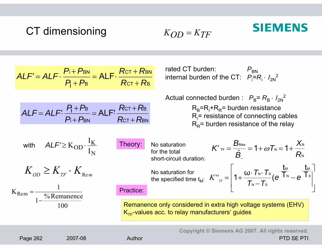
BCT
BNCT
B
BNi ALFi RR
RRPPPPALFALF'
++
⋅=++
⋅=rated CT burden: PBNinternal burden of the CT: Pi=Ri ⋅ I2N
2
Actual connected burden : PB= RB ⋅ I2N2
RB=Rl+RR= burden resistanceRl= resistance of connecting cablesRR= burden resistance of the relay BNCT
BCT
BNi
B ALF'iRRRR
PPPPALF'ALF
++
⋅=++
⋅=
N
KOD I
IK' ⋅≥ALF No saturation for the totalshort-circuit duration: N
NN
~
MaxTF 11
RXT
BBK' +=+== ωˆ
⎥⎥
⎦
⎤
⎢⎢
⎣
⎡−
−⋅⋅
+=−−
S
M
N
M
SN
SN Tt
Tt
(ω1 eeTTTT
TFK ''No saturation for the specified time tM:
mTFOD KKK Re⋅≥
100Remanence %1
1K mRe−
=
with
CT dimensioning
Theory:
Practice:
TFKODK =
Remanence only considered in extra high voltage systems (EHV)KTF-values acc. to relay manufacturers‘ guides

Power Transmission and Distribution
Author
Page 263 2007-08Copyright © Siemens AG 2007. All rights reserved.
PTD SE PTIAuthor
Practical CT requirements Transient over-dimensioning factors KTF (AR not considered)
5KTF ≥Distance7SA6 and 7SA522 30ms)T if 1( 2K NTF <≥≥
Fault atbalance point:Close-in fault:
Internal fault External fault
Transformer Differential KTF≥ 0.75 KTF≥ 1.2 7UT6 (Saturation free (Saturation free
time ≥ 4 ms) time ≥ 5 ms)
Line differential KTF≥ 0.5 KTF≥ 1.27SD61 (Saturation free (Saturation free
time ≥ 3 ms) time ≥ 5 ms)
Bus differential KTF≥ 0.5 KTF≥ 0.57SS52 (Saturation free (Saturation free
time ≥ 3 ms) time ≥ 3 ms)
Overcurrent ALF‘≥ I>>setting/ IN, at least 207SJ56

Power Transmission and Distribution
Author
Page 264 2007-08Copyright © Siemens AG 2007. All rights reserved.
PTD SE PTIAuthor
CT dimensioning for Example differential protection (1)
1. Calculation of fault currents
Net
∆ IL ∆ IL∆ IT
F1 F2 F3 F4
7UT61 7SD61
Impedances related to 20 kV:
[ ] Ω 0.133000
220MVA''SCS
2kV2NU
N Z:Net ==⎥⎦⎤
⎢⎣⎡
=
[ ][ ] Ω 1.2
100%12
40
220100
%MVAT-NP
2kV2NU
T Z:Transf. =⋅=⋅⎥⎦⎤
⎢⎣⎡
= Tu
[ ] [ ] Ω 3,20,48Ω/km'LzkmlL Z:Line =⋅=⋅=
Impedances related to 110 kV:
[ ] Ω 4.033000
2110MVA''SCS
2kV2NU
N Z:Net ==⎥⎦⎤
⎢⎣⎡
=
110 kV, 3 GVA
110/20 kV40 MVAuT=12%
OH-line: l = 8 km, zL‘= 0,4 Ω/km
300/1A 1200/1A 200/1A 200/1A
[ ][ ] Ω 36.3
100%12
40
2110100
%MVAT-NP
2kV2NU
T Z:Transf. =⋅=⋅⎥⎦⎤
⎢⎣⎡
= Tu

Power Transmission and Distribution
Author
Page 265 2007-08Copyright © Siemens AG 2007. All rights reserved.
PTD SE PTIAuthor
F1 kA 17.34.03Ω
3110kV/1.1
NZ3/NU1.1
F1I =⋅
=⋅
=
kA 1.7336.3Ω4.03Ω
3110kV/1,1
TZNZ3/NU1.1
F2I =+
⋅=
+⋅
= kA 2.8 3.21.2Ω0.13Ω320kV/1,1
LZTZNZ3/NU1.1
F4I =Ω++
⋅=
++⋅
=F2
Dimensioning of the 110 kV CTs for the transformer differential protection:
Manufacturer recommends for relay 7UT61: 1) Saturation free time ≥ 4ms for internal faults2) Over-dimensioning factor KTF ≥ 1,2
for through flowing currents (external faults)The saturation free time of 3 ms corresponds to KTF≥ 0,75 See diagram, page 59
Criterion 1) therefore reads:
43300
173000,75NIF1I
TFKALF' =⋅=⋅≥ 7300
17301,2NIF2I
TFKALF' =⋅=⋅≥
For criterion 2) we get:
kA 9.55 1.2Ω0.13Ω
320kV/1.1ZZ
3/U1.1ITN
NF3 =
+⋅
=+
⋅=F3
F4
The 110 kV CTs must be dimensioned according to criterion 1).
CT dimensioning for Example differential protection (2)

Power Transmission and Distribution
Author
Page 266 2007-08Copyright © Siemens AG 2007. All rights reserved.
PTD SE PTIAuthor
CT dimensioning for Example differential protection (3)
We try to use a CT type: 300/1, 10 VA, 5P?, internal burden 2 VA.
1.1643102
5.22' =⋅++
=⋅+
+≥ ALF
ratedPiPoperationPiP
ALF
Specification of the CTs at the 20 kV side of the transformer:Chosen, with a security margin : 300 /1 A, 5P20, 10 VA, R2≤ 2 Ohm (Pi ≤ 2VA)
It is good relaying practice to choose the same dimensioning as for the CTs on the 110 kV side:
1200/1, 10 VA, 5P20, R2≤ 2 Ohm (Pi ≤ 2VA)
Dimensioning of the 20 kV CTs for line protection:
For relay 7SD61, it is required: 1‘) Saturation free time ≥ 3ms for internal faults2‘) Over-dimensioning factor KTF ≥ 1.2
for through flowing currents (external faults)
24200
95500.5NIF3I
TFKALF' =⋅=⋅≥ 8.16=⋅=⋅≥200
28001.2IIKALF'
N
F4TF
The 20 kV line CTsmust be dimensioned according to criterion 1‘).
(Connected burden estimated to about 2.5 VA)
The saturation free time of 3 ms corresponds to KTF≥ 0.5 See diagram, page 59
Criterion 1‘) therefore reads: For criterion 2‘) we get:

Power Transmission and Distribution
Author
Page 267 2007-08Copyright © Siemens AG 2007. All rights reserved.
PTD SE PTIAuthor
For the 20 kV line we have considered the CT type: 200/5 A, 5 VA, 5P?, internal burden ca. 1 VA
8245111' =⋅
++
=⋅+
+≥ ALF
ratedPiPoperationPiP
ALF
Specification of line CTs:
We choose the next higher standard accuracy limit factor ALF=10 : Herewith, we can specify: CT Type TPX, 200/5 A, 5 VA, 5P10, R2≤ 0.04 Ohm ( Pi≤ 1 VA)
(Connected burden about 1 VA)
CT dimensioning for Example differential protection (4)