Embed Size (px)
Citation preview

KippZonen
&
03
05
36
0
24
SIGNAL AMPLIFIER 4 20 mA
INSTRUCTION MANUAL

1INSTRUCTION MANUAL CT 24
IMPORTANT USER INFORMATION
Reading this entire manual is recommended for full understanding of the use of this product
The exclamation mark within an equilateral triangle is intended to alert the user to the presence of important operating and maintenance instructions in the literature accompanying the instrument.
Should you have any comments on the product or this manual we will be pleased to receive them at:
Kipp & Zonen B.V. Röntgenweg 1 2624 BD Delft Holland P.O. Box 507 2600 AM Delft Holland Phone +31 (0)15 2698000 Fax +31 (0)15 2620351 E-mail [email protected]
Kipp & Zonen reserve the right to make changes in the specifications without prior notice.
IMPORTANT USER INFORMATION

2 INSTRUCTION MANUAL CT 24
WARRANTY AND LIABILITY
Kipp & Zonen guarantees that the product delivered has been thoroughly tested to ensure that it meets its published specifications. The warranty included in the conditions of delivery is valid only if the product has been installed and used according to the instructions supplied by Kipp & Zonen. User made modifications can affect the validity of the CE declaration.
Kipp & Zonen shall in no event be liable for incidental or consequential damages, including without limitation, lost profits, loss of income, loss of business opportunities, loss of use and other related exposures, however caused, arising from the faulty and incorrect use of the product.
COPYRIGHT© 2003 KIPP & ZONEN
All rights reserved. No part of this publication may be reproduced, stored in a retrieval system or transmitted in any form or by any means, without permission in written form from the company.
IMPORTANT USER INFORMATION

3INSTRUCTION MANUAL CT 24
Declaration of Conformity
According to EC guideline 89/336/EEC 73/23/EEC
We Kipp & Zonen B.V. Röntgenweg 1 2624 BD Delft
Declare under our sole responsibility that the product
Type: CT 24 Name: Solar Sensor Amplifier 4 – 20 mA
To which this declaration relates is in conformity with the following standards:
Imissions EN 50082-1 Group standard IEC 1000-4-2 IEC 1000-4-3 IEC 1000-4-4
Emissions EN 50081-1 Group standard EN 55022
Safety standard IEC 1010-1
Following the provisions of the directive
CE DECLARATION OF CONFORMITY
B.A.H. Dieterink President
KIPP & ZONEN B.V.

4 INSTRUCTION MANUAL CT 24

5INSTRUCTION MANUAL CT 24
TABLE OF CONTENTS
WARRANTY AND LIABILITY 2
Declaration of Conformity 3
1. GENERAL INFORMATION 7
2. SPECIFICATIONS 9
3. CONNECTION OF THE CT 24 113.1 Minimising interference 123.2 Selecting the supply voltage 133.3 Connection for current output 13
4. NEGATIVE INPUT SIGNALS 17
5. CALIBRATION PROCEDURE 195.1 Standard calibration 195.2 Special calibration. 20

6 INSTRUCTION MANUAL CT 24

7INSTRUCTION MANUAL CT 24
1. GENERAL INFORMATION
With the CT 24 it is possible to convert a low level voltage output from a solar sensor to the standard level of 4 – 20 mA or (using the supplied 500 Ohm resistor) to a 2 – 10 Volt signal. The CT 24 amplifier is designed to use with Kipp & Zonen solar sensors, to allow long cables between sensor and data logger without external interference.
The large operation temperature range from - 30°C to + 70°C and the waterproof housing (IP 65) makes that the CT 24 can be used under the same conditions as all solar sensors.
The amplification can be adjusted from the standard 0 – 20 mV is 4 – 20 mA to a value that takes the calibration factor of the sensor into account, like 0 – 1000 W/m² is 4 – 20 mA. Even negative inputs are allowed through a positive shift of the zero point from +4 to + 8 mA. This allows for negative input signals of about 250 W/m² like a pyrgeometer produces.
The CT 24 is protected against reversed polarity, voltage surges on input and output lines and is shielded against EMF disturbance. For pyranometers with temperature sensors there are special connector strips in the CT 24 to connect these sensors from in going to out-going cable.
GENERAL INFORMATION

8 INSTRUCTION MANUAL CT 24

9INSTRUCTION MANUAL CT 24
2. SPECIFICATIONS
Power supply @ RL 125 +12 to +30 VDC Input range -5 to +20 mV Gain adjust +0.5 to +1.0 mA / mV Zero adjust +3 to +8 mA Temperature range (operating) -30°C to +70°C Housing Aluminium, grey lacquered Dimensions W x D x H 64 x 58 x 34 mm Water proof IP 65 / DIN 40050 Cable glands size 4 to 6,5 mm Voltage output +2 to +10 V
SPECIFICATIONS

10 INSTRUCTION MANUAL CT 24

11INSTRUCTION MANUAL CT 24
3. CONNECTION OF THE CT 24
The CT 24 is meant to boost the (low level) output signal of a solar sensor. Therefore the CT 24 amplifier needs to be close to the sensor to maintain a high signal to noise ratio in the cable.The internal layout of the CT 24 is shown in figure 3.1.
figure 3.1 Internal layout of the CT 24
To prevent errors due to current loops between inputand output it is necessary that the sensor outputsare floating (not connected to ground) or that the ( )from the power supply is not connected to ground.
In case of doubt check the impedance of the sensor wiresagainst the sensor housing, this should be infinite.
CONNECTION OF THE CT 24
OUTPUTINPUT
GND
GNDZERO ADJUST
GAIN ADJUST

12 INSTRUCTION MANUAL CT 24
3.1 Minimising interference
To obtain maximum signal to noise ratio both before and after the CT 24, it is advised to connect the CT 24 as described in this chapter.
All Kipp & Zonen sensor cables have an internal shield that has to be connected to the ground (housing) of the CT 24. For this purpose pin 1 of the input connector strips can be used or one of the screws that holds the PC board in place. Also the outgoing cable must have an internal shield connected to the ground inside the CT 24. For this purpose pin 1 of the output connector strips can be used or one of the screws that holds the PC board in place.
If you don’t want to connect the cable shields to the housing but only interconnect with each other, use one of the interconnections instead of pin 1. Make sure that the cable diameter is within the size that the cable glands can hold (4 – 6.5 mm)
SHIELD 1 1 SHIELD SIGNAL INPUT 2 2 SIGNAL OUTPUT SIGNAL + INPUT 3 3 SIGNAL + OUTPUT
INTERCONNECTION 4 4 INTERCONNECTION INTERCONNECTION 5 5 INTERCONNECTION INTERCONNECTION 6 6 INTERCONNECTION INTERCONNECTION 7 7 INTERCONNECTION INTERCONNECTION 8 8 INTERCONNECTION INTERCONNECTION 9 9 INTERCONNECTION
figure 3.2 internal connection strip
CONNECTION OF THE CT 24
13INSTRUCTION MANUAL CT 24
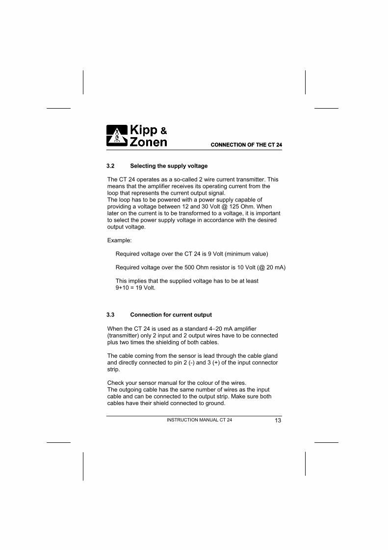
3.2 Selecting the supply voltage
The CT 24 operates as a so-called 2 wire current transmitter. This means that the amplifier receives its operating current from the loop that represents the current output signal. The loop has to be powered with a power supply capable of providing a voltage between 12 and 30 Volt @ 125 Ohm. When later on the current is to be transformed to a voltage, it is important to select the power supply voltage in accordance with the desired output voltage.
Example:
Required voltage over the CT 24 is 9 Volt (minimum value) Required voltage over the 500 Ohm resistor is 10 Volt (@ 20 mA)
This implies that the supplied voltage has to be at least 9+10 = 19 Volt.
3.3 Connection for current output
When the CT 24 is used as a standard 4 20 mA amplifier (transmitter) only 2 input and 2 output wires have to be connected plus two times the shielding of both cables.
The cable coming from the sensor is lead through the cable gland and directly connected to pin 2 (-) and 3 (+) of the input connector strip.
Check your sensor manual for the colour of the wires. The outgoing cable has the same number of wires as the input cable and can be connected to the output strip. Make sure both cables have their shield connected to ground.
CONNECTION OF THE CT 24CONNECTION OF THE CT 24

14 INSTRUCTION MANUAL CT 24
Input connector pins number 4 till 9 are interconnected with the output connector pins and can be used to transfer the signal from temperature sensors like a Pt100 or thermistor to the output cable.
figure 5.3 connection for current output
Shield
Signal +
Signal -

15INSTRUCTION MANUAL CT 24
3.4 Connection for voltage output
When a voltage signal is needed directly from the CT 24, the conversion from current to voltage can be made inside the CT 24. For this purpose a precision 500 Ohm resistor is supplied that can be connected through the connection strip. The wires used to supply the current and the wires that carry the voltage output can not be combined. Even though the return from the current loop and the low of the voltage output are connected to the same level, the voltage drop over the cable makes it necessaryto use separate wires for the voltage output.
figure 3.4 voltage output connection
Power supply + Signal + Signal –Power supply –
Shield

16 INSTRUCTION MANUAL CT 24
So when the CT 24 is used with a voltage output, 2 input and 4 output wires have to be connected plus two times the shielding of both cables.
Of course any other RL can be used to transform the output current to a voltage, as long as the guideline from chapter 5 is followed.

17INSTRUCTION MANUAL CT 24
4. NEGATIVE INPUT SIGNALS
When using a pyrgeometer as input, the signal can be both positive and negative. To allow for negative inputs the zero point from the CT 24 can be adjusted to + 8mA. (see fig 3.1 zero adjust)
Example with a CG 1:
Sensor output –250 to + 250 W/m2 = -3.750 mV to + 3.750 mV Gain is set to 1 mA / mV Output range is 3.75 x 2 = 7.5 mA
To see both negative and positive signals on the output the zero has to be shifted +4 mA (3.75 minimal) to +8 mA.
See the next chapter for the calibration procedure.
NEGATIVE INPUT SIGNALS

18 INSTRUCTION MANUAL CT 24

19INSTRUCTION MANUAL CT 24
5. CALIBRATION PROCEDURE
Calibration can be performed in two ways, either the CT 24 is calibrated standard with an amplification of 1mA per 1 mV and no offset adjusted (see chapter 5.1) Or a special calibration is made where the amplification and / or offset are adapted to the sensor (see chapter 5.2).
Necessary equipment for calibration:
- accurate voltage source - power supply ( +12 to +30 Volt) - accurate multimeter ( current and voltage) - small screwdriver to adjust the potentiometers - Resistor (RS) equal to the sensor element impedance
5.1 Standard calibration
To perform a standard calibration, connect RS in the CT 24 to the input terminal strip pin 2 and 3. The power supply has to be connected to the output pins 2 and 3. Measure the loop current with the multimeter on mA range. In this situation a zero input is simulated and the zero output can be adjusted to +4 mA with the zero adjust potentiometer. Then a +16 mV signal has to be applied to the input. With the gain potentiometer the output is adjusted to +20 mA. This gives a maximum full-scale input of +16 mV.
CALIBRATION PROCEDURE

20 INSTRUCTION MANUAL CT 24
5.2 Special calibration.
With special calibration is meant that the sensitivity of the sensor (pyranometer) is used to adjust the gain. This is to obtain for instance a conversion of 200 W/m2 per mA.
Example:
CM 11 with a sensitivity of 5.14 x 10⁻⁶ V / W/m2 and max. irradiance of 2000 W/m2
The zero point is set as described above under standard calibration.
For 200 W/m2 / mA the applied voltage to the input to set the gain, is calculated in the following way:
5.14 x 10-6 x 2000 = 10,28 mV, and adjust the output to +4 mA + (2000/200) = 14 mA
This should always be smaller than 20 mA.
An input signal change of 0 to 2000 W/m2 gives an output change of 4 to 14 mA. With the 500 Ohm resistor this results in a voltage change of 2 to 7 Volt.
Depending on the sensor output it can be better to use a conversion of 50 or 100 W/m2 per mA. Of course using the total +16 mA range gives the optimal resolution on the output.
CALIBRATION PROCEDURE

21INSTRUCTION MANUAL CT 24
6. PART NUMBERS
CT 24 0305 710 Resistor 500 2686 002 Instruction manual 0305 260
PART NUMBERS

22 INSTRUCTION MANUAL CT 24
KippZonen
&
www.kippzonen.com
Holland Kipp & Zonen B.V.
Röntgenweg 1
2624 BD DELFT
T +31 15 269 8000
F +31 15 262 0351
UK Kipp & Zonen Ltd.
Suite 3, The Old School,
Wragby Road, Langworth
LINCOLN, Lincolnshire LN3 5BJ
T +44 1522 754 551
F +44 1522 754 552
Germany Gengenbach Messtechnik
Heinrich-Otto-Strasse 3
D-73262 REICHENBACH/FILS
T +49 7153 59423
F +49 7153 59424
USA Kipp & Zonen USA Inc.
125, Wilbur Place
BOHEMIA/NY 11716
T +1 631 589 2065
F +1 631 589 2068
France Kipp & Zonen S.A.R.L.
7, avenue Clément Ader
ZA Ponroy - Bât. M
F-94420 LE PLESSIS TREVISE
T +33 1 49 62 4104
F +33 1 49 62 4102
Our customer support
remains at your disposal
for any maintenance or
repair, calibration,
supplies and spares.
The address is as
follows:
Für Servicearbeiten und
Kalibrierung, Verbrauchs-
material und Ersatzteile
steht Ihnen unsere
Customer Support
Abteilung unter folgender
Adresse zur Verfügung:
Notre service 'Support Clientèle'
reste à votre entière disposition
pour tout problème de
maintenance, réparation ou
d'étalonnage ainsi que pour les
accessoires et pièces de
rechange. Leur adresse est la
suivante :
Customerustomer Supportupport
WWW.RG-MESSTECHNIK.DE