Embed Size (px)
Citation preview

CUSTOMERSUPPORT
INFORMATION
Order toll-free in the U.S.: Call 877-877-BBOX (outside U.S. call 724-746-5500)FREE technical support 24 hours a day, 7 days a week: Call 724-746-5500 or fax 724-746-0746Mailing address: Black Box Corporation, 1000 Park Drive, Lawrence, PA 15055-1018Web site: www.blackbox.com • E-mail: [email protected]
JULY 1998MT136AMT137CMT138CMT139CMT140C
CSU/DSU MS DBU
CANCEL
ENTER
1
4
7
*
A
D
SHIFT
2
5
8
0
B
E
3
6
9
#
C
F
QUICK
CSU/DSU MS DBU
ALMTST
CDRD
TDCS
RS

1
TRADEMARKS
TRADEMARKS USED IN THIS MANUAL
Accunet and AT&T are registered trademarks of American Telephone andTelegraph Company.
VT100 is a trademark of Digital Equipment Corporation.
HP and OpenView are registered trademarks of Hewlett-Packard.
IBM and NetView are registered trademarks of International Business MachinesCoporation.
MCI is a registered trademark of MCI Telecommunications Corporation.
MNP is a registered trademark of Microcom Systems, Inc.
Siemens is a registered trademark of Siemens Aktiengesellschaft.
UL is a registered trademark of Underwriters Laboratories Incorporated.
Sprint and US Sprint are registered trademarks of U.S. Sprint CommunicationsCo. Ltd.
Any other trademarks mentioned in this manual are acknowledged to be theproperty of the trademark owners.

2
CSU/DSU MS DBU
FEDERAL COMMUNICATIONS COMMISSIONAND
INDUSTRY CANADARADIO FREQUENCY INTERFERENCE STATEMENTS
This equipment generates, uses, and can radiate radio frequency energy and if notinstalled and used properly, that is, in strict accordance with the manufacturer’sinstructions, may cause interference to radio communication. It has been testedand found to comply with the limits for a Class A computing device in accordancewith the specifications in Subpart J of Part 15 of FCC rules, which are designed toprovide reasonable protection against such interference when the equipment isoperated in a commercial environment. Operation of this equipment in aresidential area is likely to cause interference, in which case the user at his ownexpense will be required to take whatever measures may be necessary to correct the interference.
Changes or modifications not expressly approved by the party responsible for compliance could void the user’s authority to operate the equipment.
This digital apparatus does not exceed the Class A limits for radio noise emission from digital apparatus set out in the Radio Interference Regulation of Industry Canada.
Le présent appareil numérique n’émet pas de bruits radioélectriques dépassant les limitesapplicables aux appareils numériques de la classe A prescrites dans le Règlement sur lebrouillage radioélectrique publié par Industrie Canada.
3
NOM STATEMENT
NORMAS OFICIALES MEXICANAS (NOM)ELECTRICAL SAFETY STATEMENT
INSTRUCCIONES DE SEGURIDAD
1. Todas las instrucciones de seguridad y operación deberán ser leídas antes deque el aparato eléctrico sea operado.
2. Las instrucciones de seguridad y operación deberán ser guardadas parareferencia futura.
3. Todas las advertencias en el aparato eléctrico y en sus instrucciones deoperación deben ser respetadas.
4. Todas las instrucciones de operación y uso deben ser seguidas.
5. El aparato eléctrico no deberá ser usado cerca del agua—por ejemplo, cercade la tina de baño, lavabo, sótano mojado o cerca de una alberca, etc..
6. El aparato eléctrico debe ser usado únicamente con carritos o pedestales quesean recomendados por el fabricante.
7. El aparato eléctrico debe ser montado a la pared o al techo sólo como searecomendado por el fabricante.
8. Servicio—El usuario no debe intentar dar servicio al equipo eléctrico más alláa lo descrito en las instrucciones de operación. Todo otro servicio deberá serreferido a personal de servicio calificado.
9. El aparato eléctrico debe ser situado de tal manera que su posición nointerfiera su uso. La colocación del aparato eléctrico sobre una cama, sofá,alfombra o superficie similar puede bloquea la ventilación, no se debe colocaren libreros o gabinetes que impidan el flujo de aire por los orificios deventilación.
10. El equipo eléctrico deber ser situado fuera del alcance de fuentes de calorcomo radiadores, registros de calor, estufas u otros aparatos (incluyendoamplificadores) que producen calor.
11. El aparato eléctrico deberá ser connectado a una fuente de poder sólo deltipo descrito en el instructivo de operación, o como se indique en el aparato.

4
CSU/DSU MS DBU
12. Precaución debe ser tomada de tal manera que la tierra fisica y la polarizacióndel equipo no sea eliminada.
13. Los cables de la fuente de poder deben ser guiados de tal manera que nosean pisados ni pellizcados por objetos colocados sobre o contra ellos,poniendo particular atención a los contactos y receptáculos donde salen delaparato.
14. El equipo eléctrico debe ser limpiado únicamente de acuerdo a lasrecomendaciones del fabricante.
15. En caso de existir, una antena externa deberá ser localizada lejos de las lineasde energia.
16. El cable de corriente deberá ser desconectado del cuando el equipo no seausado por un largo periodo de tiempo.
17. Cuidado debe ser tomado de tal manera que objectos liquidos no seanderramados sobre la cubierta u orificios de ventilación.
18. Servicio por personal calificado deberá ser provisto cuando:
A: El cable de poder o el contacto ha sido dañado; u
B: Objectos han caído o líquido ha sido derramado dentro del aparato; o
C: El aparato ha sido expuesto a la lluvia; o
D: El aparato parece no operar normalmente o muestra un cambio en sudesempeño; o
E: El aparato ha sido tirado o su cubierta ha sido dañada.

5
ABOUT THIS MANUAL
About This ManualThis manual is arranged so you can quickly and easily find the informationyou need. The following is an overview of the contents of this manual:
• Chapter 1, Introduction, familiarizes you with DDS, Switched 56, SNMP,and TELNET. This chapter also includes CSU/DSU MS DBU highlightsand describes the options that may be purchased for use with the DSU.
• Chapter 2, Installation, describes the DSU connectors (pin assignmentsare given in Appendix A) and provides an installation diagram.
• Chapter 3, Operation, explains how to operate your DSU using eitherthe front panel or a VT100™ terminal interface.
• Chapter 4, Applications, provides examples of some common DSUapplications, including network diagrams.
• Chapter 5, Configuration Overview, explains how to access the DSUconfiguration menu, including information on the different configurationmethods. This chapter also provides a front-panel menu tree.
• Chapters 6 through 11 provide brief explanations for selections made in theConfiguration menus. These chapters are based on the front-panel menubranches of the Configuration menu: Network Options, DTE Options,Test Options, Dial Options, Management, and Utilities.
• Chapter 12, Testing and Troubleshooting, describes the testing optionsavailable with the CSU/DSU MS DBU and gives troubleshooting information.
• Chapter 13, Activating Dial Functions, describes the Dial options availablefrom the Main menu.
• Chapter 14, Viewing Status Information, provides information on the statusmenus available for the base unit as well as the DBU cards.
• Appendix A provides pinouts for the connectors of the DSU and the DBUand Ethernet cards.
• Appendix B shows the AT commands available for the DSU.
• Appendix C describes the terminal menu interface (accessed througha VT100 terminal or a TELNET session).
• Appendix D provides information on the unit’s configuration profiles.
6
CSU/DSU MS DBU
• Appendix E contains a DSU-to-modem interconnect diagram for a modem tail-circuit application.
• Appendix F contains product specifications.
7
FCC REGULATIONS
FCC regulations require that the following information be provided in thismanual:
1. This equipment complies with Part 68 of the FCC rules. On the bottom ofthe equipment housing is a label that shows the FCC registration numberand ringer equivalence number (REN) for this equipment. If requested,provide this information to the telephone company.
2. If this equipment causes harm to the telephone network, the telephonecompany may temporarily discontinue service. If possible, advance notificationis given; otherwise, notification is given as soon as possible. The telephonecompany will advise the customer of the right to file a complaint with the FCC.
3. The telephone company may make changes in its facilities, equipment,operations, or procedures that could affect the proper operation of thisequipment; advance notification and the opportunity to maintainuninterrupted service are given.
4. If experiencing difficulty with this equipment, please contact Black Boxfor repair and warranty information. The telephone company may requirethis equipment to be disconnected from the network until the problem iscorrected, or it is certain the equipment is not malfunctioning.
5. This unit contains no user-serviceable parts.
6. An FCC-compliant telephone cord with a modular plug is provided with thisequipment. In addition, an FCC-compliant cable appropriate for the dial-backup option ordered is provided with this equipment. This equipmentis designed to be connected to the telephone network or premises wiringusing an FCC-compatible modular jack that is Part 68 compliant.
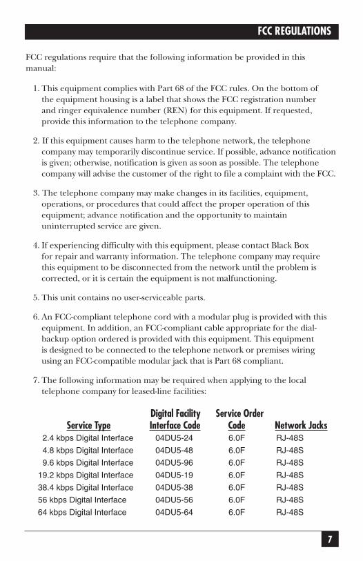
7. The following information may be required when applying to the localtelephone company for leased-line facilities:
Digital Facility Service OrderService Type Interface Code Code Network Jacks
2.4 kbps Digital Interface 04DU5-24 6.0F RJ-48S
4.8 kbps Digital Interface 04DU5-48 6.0F RJ-48S
9.6 kbps Digital Interface 04DU5-96 6.0F RJ-48S
19.2 kbps Digital Interface 04DU5-19 6.0F RJ-48S
38.4 kbps Digital Interface 04DU5-38 6.0F RJ-48S
56 kbps Digital Interface 04DU5-56 6.0F RJ-48S
64 kbps Digital Interface 04DU5-64 6.0F RJ-48S

8
CSU/DSU MS DBU
8. The following information may be required when applying to the localtelephone company for a dial-up line for the V.34 Module:
Service Type SOC REN FIC USOCLoop Start (V.34) 9.0Y 0.8B 02LS2 RJ-11C
9. The following information may be required when applying to the localtelephone company for Switched 56 service for the S4W DBU Card:
Service Type SOC REN FIC USOCPSDS 6.0F N/A 04D45-56B RJ-48S
10. The following information may be required when applying to the localtelephone company for ISDN service for the ISDN Module:
Service Type SOC REN FIC USOCBasic Rate ISDN 6.0F N/A 021S5 RJ-49
11. The REN is useful in determining the quantity of devices you may connect toyour telephone line and still have all of those devices ring when your numberis called. In most areas, the sum of the RENs of all devices should not exceedfive. To be certain of the number of devices you may connect to your line asdetermined by the REN, call your telephone company to determine themaximum REN for your calling area.
12. This equipment may not be used on coin service provided by the telephonecompany. Connection to party lines is subject to state tariffs. (Contact yourstate public utility commission or corporation commission for information.)
9
ISDN SERVICE ORDERING INFORMATION
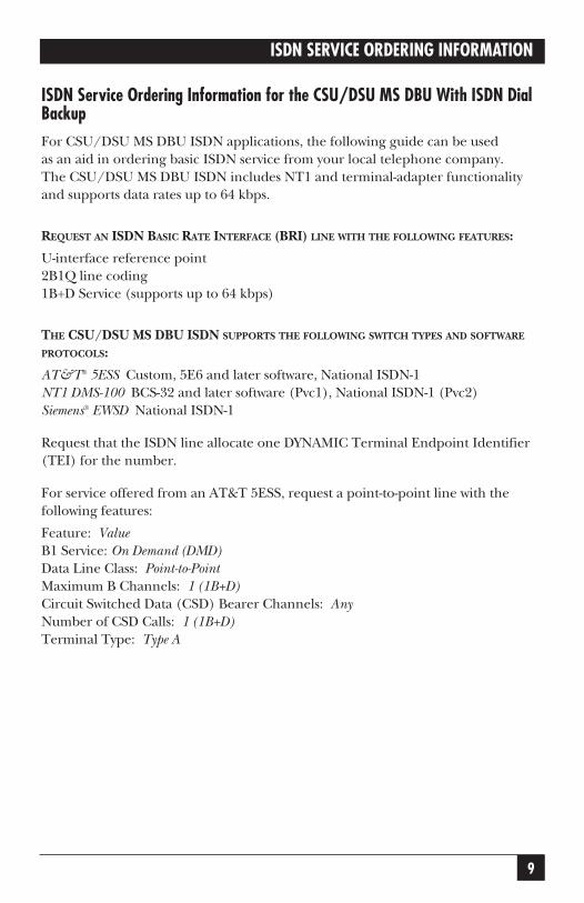
ISDN Service Ordering Information for the CSU/DSU MS DBU With ISDN DialBackupFor CSU/DSU MS DBU ISDN applications, the following guide can be usedas an aid in ordering basic ISDN service from your local telephone company.The CSU/DSU MS DBU ISDN includes NT1 and terminal-adapter functionalityand supports data rates up to 64 kbps.
REQUEST AN ISDN BASIC RATE INTERFACE (BRI) LINE WITH THE FOLLOWING FEATURES:
U-interface reference point2B1Q line coding1B+D Service (supports up to 64 kbps)
THE CSU/DSU MS DBU ISDN SUPPORTS THE FOLLOWING SWITCH TYPES AND SOFTWARE
PROTOCOLS:
AT&T® 5ESS Custom, 5E6 and later software, National ISDN-1NT1 DMS-100 BCS-32 and later software (Pvc1), National ISDN-1 (Pvc2)Siemens® EWSD National ISDN-1
Request that the ISDN line allocate one DYNAMIC Terminal Endpoint Identifier(TEI) for the number.
For service offered from an AT&T 5ESS, request a point-to-point line with thefollowing features:
Feature: ValueB1 Service: On Demand (DMD)Data Line Class: Point-to-PointMaximum B Channels: 1 (1B+D)Circuit Switched Data (CSD) Bearer Channels: AnyNumber of CSD Calls: 1 (1B+D)Terminal Type: Type A

10
CSU/DSU MS DBU
TURN THE FOLLOWING FEATURES OFF:
Packet Mode DataMulti-line HuntMultiple Call AppearancesElectronic Key Telephone Sets (EKTS)Shared Dictionary NumbersAccept Special Type of NumberIntercom GroupsNetwork Resource Selector (Modem Pools)Message WaitingHuntingInterLata Competition
FOR SERVICE OFFERED FROM A NORTHERN TELECOM DMS-100, REQUEST A POINT-TO-POINT
MULTI-POINT LINE WITH THE FOLLOWING FEATURES:
Line Type: Basic Rate, FunctionalElectronic Key Telephone Sets (EKTS): NoCall Appearance Handling (CACH): NoNon-Initializing Terminal: NoCircuit Switched Service: YesPacket Switched Service: NoTEI: DynamicBearer Service: Circuit Switched voice and data permitted on any B channel (packet modedata not permitted)

11
CONTENTS
ContentsChapter Page
1. Introduction........................................................................................................15
1.1 Overview ....................................................................................................15
1.2 DDS Operation ........................................................................................16
1.3 Switched 56 Operation ............................................................................16
1.4 SNMP ........................................................................................................16
1.5 TELNET ....................................................................................................17
1.6 Dial-Backup Operation ............................................................................17
1.7 Dial Backup Modes ..................................................................................17
2. Installation ..........................................................................................................19
2.1 Unpack, Inspect, and Power Up ..............................................................19
2.2 Rear Panel ................................................................................................20
3. Operation............................................................................................................24
4. Applications ........................................................................................................30
4.1 LAN Application with SNMP/TELNET Management ..........................30
4.2 Dial-Backup Application ..........................................................................33
5. Configuration Overview ....................................................................................36
6. Configuring Network Options ..........................................................................42
6.1 Loop Rate ..................................................................................................43
6.2 Network Address ......................................................................................43
6.3 Remote Configuration..............................................................................44
6.4 Network Type ............................................................................................44
6.5 Clock Source ............................................................................................44
7. Configuring DTE Options ................................................................................45
7.1 DTE Rate ..................................................................................................48
7.2 Connector Type ........................................................................................48
7.3 Data Format ..............................................................................................48
7.4 DTE Command Option............................................................................49

12
CSU/DSU MS DBU
Chapter Page
7.5 Transmit Clock..........................................................................................49
7.6 Clear to Send (CS) Options ....................................................................49
7.7 Anti-Stream................................................................................................50
7.8 CD Options................................................................................................50
7.9 Data Terminal Ready (TR) Options........................................................50
7.10 Data Set Ready (SR) Options ..................................................................50
8. Configuring Test Options ..................................................................................51
9. Configuring Dial Options ..................................................................................54
9.1 Phone Numbers ........................................................................................55
9.2 SW56 Auto Answer....................................................................................55
9.3 DBU Options ............................................................................................56
9.3.1 Standard DBU Options ..................................................................56
9.3.2 DBU Options for S4W ....................................................................59
9.3.3 DBU Options for V.34 Card ............................................................60
9.3.4 DBU Options for ISDN Card ..........................................................61
9.3.5 DBU Passcode ..................................................................................61
10.Configuring Management Functions................................................................63
10.1 Interface ....................................................................................................63
10.2 Control Rate ..............................................................................................63
10.3 IP Options..................................................................................................64
10.3.1 Unit IP Address ................................................................................64
10.3.2 Subnet Mask ....................................................................................64
10.3.3 Gateway IP Address ..........................................................................64
10.3.4 IP Security ........................................................................................64
10.3.5 IP Filter Address ..............................................................................64
10.4 SNMP Options ..........................................................................................65
10.5 TELNET Options......................................................................................66
10.6 Entering Letters Using the Front Panel ..................................................66

13
CONTENTS
Chapter Page
11.Configuring Unit Utilities ..................................................................................68
11.1 Manual Command ....................................................................................69
11.2 Time/Date ................................................................................................70
11.3 Software Revision ......................................................................................71
11.4 LAN MAC Address ....................................................................................71
11.5 Serial Number ..........................................................................................71
12.Testing and Troubleshooting ............................................................................72
12.1 Test Overview ............................................................................................72
12.1.1 Initiating a Test ................................................................................72
12.1.2 Test Status Display............................................................................73
12.1.3 Exiting a Test....................................................................................74
12.2 Troubleshooting ......................................................................................74
12.2.1 Messages from the DSU/CSU ........................................................74
12.2.2 Troubleshooting New Installations ................................................76
12.3 Local Unit Diagnostics..............................................................................77
12.3.1 DTE & Loop (LL)............................................................................78
12.3.2 Loop Only (RT) ..............................................................................79
12.3.3 DTE Only..........................................................................................79
12.3.4 DTE With Test Pattern ....................................................................80
12.3.5 Test Pattern ......................................................................................81
12.3.6 Self-Test ............................................................................................82
12.4 Remote Unit Diagnostics..........................................................................82
12.5 DBU Connection ......................................................................................84
13.Activating Dial Functions ..................................................................................86
14.Viewing Status Information ..............................................................................88
Appendix A. Pinouts ..............................................................................................92
Appendix B. AT Commands ..................................................................................96

14
CSU/DSU MS DBU
Chapter Page
Appendix C. Terminal Menu Structure ................................................................98
C.1 Status Messages ......................................................................................102
C.2 Local/Remote Configuration Menus....................................................102
C.2.1 DSU Configuration (DTE, Network, and Test Options) ............103
C.2.2 DBU Configuration ......................................................................103
C.2.3 Management Configuration..........................................................104
C.2.4 Utility Configuration......................................................................105
C.3 Local/Remote Test Menus ....................................................................106
C.4 Dial SW56/Dial DBU..............................................................................106
C.4.1 Dial SW56 Options ........................................................................106
C.4.2 Dial DBU ........................................................................................107
Appendix D. Configuration Profiles....................................................................108
Appendix E. DSU-to-Modem Interconnect ........................................................111
Appendix F. Specifications ..................................................................................112

15
CHAPTER 1: Introduction
1. Introduction
1.1 OverviewThe CSU/DSU MS DBU (data service unit with embedded SNMP) providesa reliable, high-speed data connection for customer data terminal equipmentthrough digital data service (DDS) lines. The CSU/DSU MS DBU has anembedded SNMP agent that provides complete SNMP access to the unit throughan integral SLIP or PPP async port. The CSU/DSU MS DBU’s unique modularapproach provides optional 10BASE-T Ethernet access for SNMP. Also, optionalmodular DBU cards provide automatic or manual dial backup for the dedicatedcircuit.
The following are features of the CSU/DSU MS DBU:
• DDS rates supported from 2.4 to 64 kbps, including 19.2 and 38.4
• 4-wire Switched 56 (SW56) operation
• Embedded SNMP and TELNET
• Control port provides SLIP and async PPP access to SNMP or VT100 terminalconfiguration
• Two option slots
• 10BASE-T Ethernet SNMP port available with the SNMP Ethernet Module
• Automatic or manual DBU
• DBU available with DBU cards; options include 4-wire Switched 56, V.34,and ISDN
• Time-of-day and weekend lockout options
The CSU/DSU MS DBU provides both V.35 and EIA-232 electrical and physicalDTE interfaces to accommodate a variety of applications.
To ensure a reliable connection, the unit features an extended receiver capabilitywhich permits operation over long loops (3.4 miles or 5.5 km of 26 AWG at56 kbps).
The 4-wire Switched 56 Module and the base unit’s integrated SW56 capabilitiesare compatible with AT&T Accunet® and Sprint® SW56 type services. The V.34

16
CSU/DSU MS DBU
Modem Module allows switched backup over the public switched telephonenetwork (PSTN). The ISDN Module is compatible with National ISDN andsupports a U-interface to the Basic Rate ISDN.
1.2 DDS OperationDDS is a nationwide service that allows interconnection and transport of data atspeeds up to 64 kbps. The local exchange carriers provide the local loop service toDDS customers and may provide data for routing Inter-LATA to an interexchangecarrier. In DDS mode, the CSU/DSU MS DBU supports 2.4-kbps to 64-kbps DDSservice rates yielding DTE rates of 2.4, 4.8, 9.6, 19.2, 38.4 (sync or async), 56 kbps,and 64 kbps. An additional rate of 57.6 is available in asynchronous mode. Theunit can be configured to run slower DTE rates (async or sync) over the 56 or 64kbps service.
1.3 Switched 56 OperationDial-up, 4-wire Switched 56 DDS allows customers to pay for data connection onlyfor the time the unit is active. The regional operating companies provide the 4-wirelocal loop service to SW56 customers. The CSU/DSU MS DBU supports DTE ratesof 2.4, 4.8, 9.6, 19.2, 38.4, and 56 kbps (synchronous) and 2.4, 4.8, 9.6, 19.2, 38.4,and 57.6 kbps (asynchronous).
1.4 SNMPThe term SNMP (Simple Network-Management Protocol) broadly refers to themessage protocols used to exchange information between the network and themanaged devices, as well as to the structure of network-management databases.SNMP has three basic components:
NETWORK MANAGER
Control program that collects, controls, and presents data pertinent to theoperation of the network devices. It resides on a network-management station.
AGENT
Control program that resides in each network device connected. This programresponds to queries and commands from the network manager and returnsrequested information or invokes configuration changes initiated by the manager.

17
CHAPTER 1: Introduction
MIB
Index to the organized data within a network device. It defines the operationparameters that can be controlled or monitored.
The CSU/DSU MS DBU supports the MIB-II standard, RFC 1213, and Black BoxEnterprise Specific MIB. MIB files are available from Black Box in the supportsection of the Black Box Web page at www.blackbox.com.
The CSU/DSU MS DBU’s embedded SNMP feature allows the unit to be accessedand controlled by a network manager either through a device running SLIP orasync PPP protocol (connected to the CONTROL port of the DSU) or througha LAN. LAN connection requires the SNMP Ethernet Module (part numberMT140C). This card provides a 10BASE-T Ethernet interface to the LAN.
1.5 TELNETTELNET provides a password-protected remote login facility for the CSU/DSU MSDBU. TELNET allows a user on a network manager to control the CSU/DSU MSDBU through the terminal menus. See Chapter 4 and Appendix C for moreinformation.
1.6 Dial-Backup OperationThe CSU/DSU MS DBU’s unique DBU cards are field-installable. See Chapter 2for information on installing DBU cards. The three backup options are describedin the following sections. Contact the local telco provider to determine whichservices are available in your area. See Chapter 4 for more information, includingan example of a dial-backup application.
1.7 Dial-Backup Modules
4-WIRE SWITCHED 56 MODULE
This dial-up 4-wire SW56 card allows customers to pay for data connection only forthe time the unit is active. The regional operating companies provide the 4-wirelocal loop service to SW56 customers. This card supports DTE rates of 2.4, 4.8, 9.6,19.2, 38.4 (asynchronous or synchronous), and 56 kbps (synchronous). Anadditional DTE rate of 57.6 kbps is available in async modes.

18
CSU/DSU MS DBU
V.34 MODULE
The V.34 card has all of a V.32 bis modem’s modes of operation, plus V.34 andV.FC modes. This allows the V.34 option to run synchronous rates up to 33.6 kbps,as opposed to the V.32 maximum of 14.4 kbps. In asynchronous mode thethroughput at 57.6 kbps is less dependent on data types.
ISDN MODULE
1B+D Basic Rate ISDN service provides the customer with a switched 56/64 kbpscircuit. In addition to 56 and 64 kbps synchronous DTE rates, the card alsosupports synchronous and asynchronous DTE rates of 2.4, 4.8, 9.6, 19.2, and38.4 kbps per CCITT V.120. The card also supports the DTE rate of 57.6 kbpsasync and is compatible with the 4-wire SW56 DBU Module.
19
CHAPTER 2: Installation
2. Installation
2.1 Unpack, Inspect, Power Up
INSPECTION
Carefully inspect the CSU/DSU MS DBU for any shipping damage. If damageis suspected, file a claim immediately with the carrier and contact Black BoxCustomer Service. Keep the original shipping container for use in shippingthe CSU/DSU MS DBU for repair or for verification of damage during shipment.
The following items are included with the CSU/DSU MS DBU:
• CSU/DSU MS DBU unit
• The user manual
• An 8-position modular to 8-position modular cable
• An 8-position modular to 8-position modular cable and a modular to femaleDB25 adapter for access to the Control/SLIP/PPP port
NOTEThe Black Box CSU/DSU MS DBU MIB is available from Black Box in thesupport section of the Black Box Web page at www.blackbox.com.
The following items are included with the DBU Modules:
• DBU Module
• An 8-position modular to 8-position modular cable for the 4-wire SW56 and1B+D ISDN dial-backup options. An 8-position modular to 4-position modularcable for the V.34 backup option.
You must provide either a male EIA-232 (standard DB25) or a male V.35 interfacecable.
For SNMP management, you must provide access to the CSU/DSU MS DBUthrough either a SLIP port, an async PPP port (requires a male DB25 connector),or a 10BASE-T Ethernet port (requires that an SNMP Ethernet Module be installed

20
CSU/DSU MS DBU
in the CSU/DSU MS DBU). See Appendix A for the pin assignments of the controlport (for SLIP and Async PPP) and the Ethernet port.
POWER UP
The CSU/DSU MS DBU is provided with a captive 8-foot power cord, terminatedby a three-prong plug that connects to a grounded 115-VAC power receptacle.
CAUTIONPower to the DSU must be provided from a grounded 115-VAC, 60-Hzreceptacle.
2.2 Rear PanelThe rear panel contains two DTE connectors that provide primary-channel V.35 orEIA-232. An 8-pin telco jack, a control port, a captive power cord, and a powerswitch are also located on the rear panel. Pin assignments for these connectors arelisted in Appendix A. The CSU/DSU MS DBU rear panel is shown in Figure 2-1with optional modules installed.

21
CHAPTER 2: Installation
Figure 2-1. Rear View.
Item FunctionDBU Interface DBU module card slot
LAN Interface SNMP Ethernet Module slot
Telco Connects to dedicated circuit
EIA-232 Connects to a DTE interface
Control Connects to a VT100 terminal or a device
running SLIP or async PPP protocol
V.35 High-speed DTE interface
Power Switch Turns power on or off
115-VAC Connection Power Cord Connection
DDS
VT 100 Terminal ordevice running SLIPor async PPP protocolDTE Device DTE Device
RJ45-to-DB25Cable
V.35 Cable
TELCO EIA-232
DBU INTERFACE LAN INTERFACE
115 VAC60HZ.15A
ISDNDBU
10 BASE TLAN
ON
OFF
CONTROLV .35
S4W, V.34, orISDN DBU Card 10BASET LAN Card
EIA232 Cable
4-wireTelco Cable
Bridge/Router
22
CSU/DSU MS DBU
DBU AND ETHERNET CARD SLOTS
CAUTIONRemove power from the unit prior to installing or removing modules.
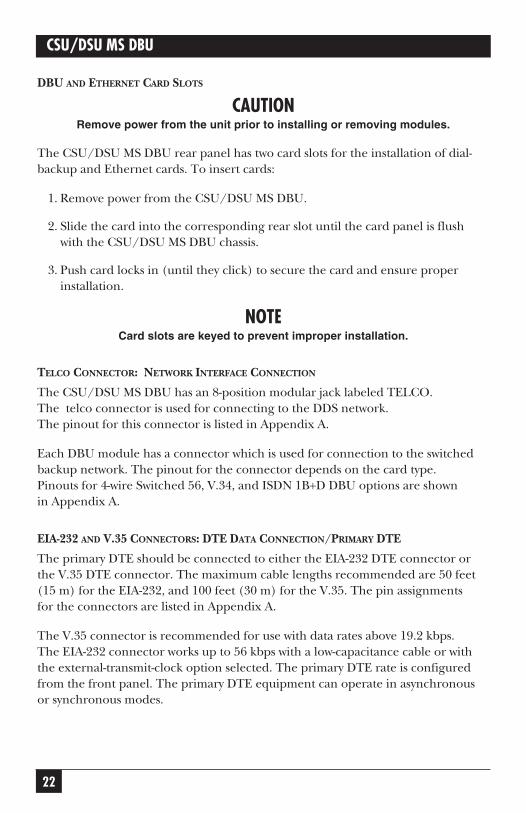
The CSU/DSU MS DBU rear panel has two card slots for the installation of dial-backup and Ethernet cards. To insert cards:
1. Remove power from the CSU/DSU MS DBU.
2. Slide the card into the corresponding rear slot until the card panel is flushwith the CSU/DSU MS DBU chassis.
3. Push card locks in (until they click) to secure the card and ensure properinstallation.
NOTECard slots are keyed to prevent improper installation.
TELCO CONNECTOR: NETWORK INTERFACE CONNECTION
The CSU/DSU MS DBU has an 8-position modular jack labeled TELCO. The telco connector is used for connecting to the DDS network.The pinout for this connector is listed in Appendix A.
Each DBU module has a connector which is used for connection to the switchedbackup network. The pinout for the connector depends on the card type.Pinouts for 4-wire Switched 56, V.34, and ISDN 1B+D DBU options are shownin Appendix A.
EIA-232 AND V.35 CONNECTORS: DTE DATA CONNECTION/PRIMARY DTE
The primary DTE should be connected to either the EIA-232 DTE connector orthe V.35 DTE connector. The maximum cable lengths recommended are 50 feet(15 m) for the EIA-232, and 100 feet (30 m) for the V.35. The pin assignmentsfor the connectors are listed in Appendix A.
The V.35 connector is recommended for use with data rates above 19.2 kbps.The EIA-232 connector works up to 56 kbps with a low-capacitance cable or withthe external-transmit-clock option selected. The primary DTE rate is configuredfrom the front panel. The primary DTE equipment can operate in asynchronousor synchronous modes.

23
CHAPTER 2: Installation
CAUTIONTo prevent possible radio-frequency interference emissions, a shieldedcable is required.
CONTROL PORT
The CSU/DSU MS DBU has an 8-position modular jack labeled CONTROL.The control port provides connection to a VT100 EIA-232 compatible interface,a device running SLIP protocol, or a device running Async PPP protocol. An 8-footadapter connector and cable provide a standard DB25 EIA-232 interface. SeeAppendix A for the control port’s pin assignments. A description of the operationof this port is in Chapter 3.
The control port also functions as the SLIP or async PPP port when configuredfor SNMP management. The pinouts are identical when operating in an SNMPmanagement mode.

24
CSU/DSU MS DBU
3. OperationThe CSU/DSU MS DBU is shown in Figure 3-1. Descriptions of each part of thefront panel follow.
Figure 3-1. Front Panel.
LCD WINDOWS
Displays menu items and messages in 2 lines by 16 characters.
ENTER
Selects active menu items. To select a menu item, press the number of the item.The menu item flashes, indicating it is activated. Press Enter to select the menuitem.
KEYPAD
The keypad contains dual-function keys numbered 0 through 9 with letters Athrough F. These keys are used to activate menu items and enter information.
SHIFT
Enter letters by pressing and releasing Shift before pressing the key representingthe desired character. To activate a menu item designated by an alpha characterrather than a number press Shift and then the letter. The menu item flashes,indicating which parameter is activated. Press Enter to select the item.
If a key is pressed without using Shift, the numbered item becomes active insteadof the lettered item.
RS CS TD RD CD ALM TST
1 2 3
4 5 6
7 8 9
0
ENTER
CANCEL
A B C
D E F
SHIFT QUICK
* #
CSU/DSU MS DBU

25
CHAPTER 3: Operation
CANCEL
Pressing the Cancel key stops the current activity and returns to the previousmenu. Repeat until the desired menu level is reached. When a submenu itemis displayed, press Cancel to exit the current display and return to the previousmenu.
UP AND DOWN ARROWS
Up and Down Arrows scroll through the submenu items available in thecurrent menu.
LED DESCRIPTIONS
The CSU/DSU MS DBU has seven LED indicators: RS, CS, TD, RD, CD, ALM,and TST.
RS (Request to Send) Reflects the status of the Request to Send pin of theDTE interface.
CS (Clear to Send) Reflects the status of the Clear to Send pin of theDTE interface.
TD (Transmit Data) This LED is active when data is transmitted fromthe DTE.
RD (Receive Data) This LED is active when data is received from thenetwork.
CD (Carrier Detect) This LED is active when frame synchronization isachieved and the CSU/DSU MS DBU is ready totransfer data.
TST (Test Mode) This LED is on whenever the unit is in test mode.
ALM (Alarm Indication) This LED activates whenever an alarm condition exists.Alarm conditions include:
• Open loop on network• No frame synchronization• Unit in dial backup• Problem on dial-backup line

26
CSU/DSU MS DBU
FRONT-PANEL MENU NAVIGATION
To choose a menu item, press the corresponding number or letter on the keypad.Press Shift to activate menu items with alpha selections. The flashing menu itemindicates which selection is activated. Press Enter to select the item. The followingsteps and Figure 3-2 illustrate how to select CSU/DSU MS DBU options:
1. Activate Configuration (CONFIG) by pressing 3. The activated menu itemwill flash. Press Enter.
2. Select LOCAL or REMOTE configuration by pressing the correspondingnumber, then press Enter.
3. Use the arrow keys to view submenu items.
4. Choose an item on the submenu such as Network Options (NETWORK OPT).
5. Activate NETWORK OPT by pressing 1. Press Enter.
6. Activate LOOP RATE options by pressing 1. Press Enter.
7. Press the number corresponding to the desired loop rate. Press Enter.
Figure 3-2. Example of Basic Menu Navigation.
FRONT-PANEL MENU STRUCTURE
The CSU/DSU MS DBU uses a multilevel menu approach to access its manyfeatures. All menu operations are displayed in the LCD window or the terminal.See Figure 3-3 for the terminal Main menu.
The opening menu is the access point to all other operations. Each Main menuitem has several functions and submenus to identify and access specific parameters.
1=LOCAL 1=NETWORK OPT.1=LOOP RATE
3=CONFIG2=REMOTE
2=DTE OPTIONS3=TEST OPTIONS4=DIAL OPTIONS5=MANAGEMENT6=UTILITIES
2=NETWORK ADDR.3=REMOTE CONFIG4=NETWORK TYPE5=CLOCK SOURCE

27
CHAPTER 3: Operation
Front-panel LCD display of the Main menu:
1=STATUS 2=TEST
3=CONFIG 4=DIAL
NOTEThe Dial selection in the Main menu is only available when a SW56network type is selected or when a DBU card is installed in the rear ofthe CSU/DSU MS DBU.
MAIN MENU
The branches of the front-panel Main menu are divided into options for Status,Test, Configuration (CONFIG), and Dial.
StatusStatus menus display all relevant information for the network and DTE interfaces.The system returns to the status display when idle. For more information,see Chapter 14, Viewing Status Information.
TestUse Test menus to control local and remote testing. Select local or remote testing,and the type of test and test pattern when required. For more information,see Chapter 12.
ConfigurationUse Configuration menus to select network and DTE operating parameters,configure testing and dialing options, select management functions, and configureunit utilities. This menu branch is divided into several chapters for easierreference. The division includes a brief overview chapter followed by a separatechapter for each of the six submenus: Configuring Network Options (Chapter 6),Configuring DTE Options (7), Configuring Test Options (8), Configuring DialOptions (9), Configuring Management Functions (10), and Configuring UnitUtilities (11).
DialDial provides manual dial backup or SW56 dial functions. For more information,see Chapter 13.

28
CSU/DSU MS DBU
VT100 Terminal Connection and OperationTo control the CSU/DSU MS DBU using a VT100 terminal:
1. Select a terminal interface through the front panel. Select 3 CONFIG,5 MANAGEMENT, 1 INTERFACE, 1 TERM CONTROL.
2. Set the CONTROL RATE to match the VT100 terminal.
3. Using the provided VT100 terminal adapter cable, connect the COM portof a VT100 compatible terminal or equivalent to the eight-pin modular jacklabeled CONTROL on the rear of the CSU/DSU MS DBU. This connection isused for both local and remote configuration.
4. Establish the connection and press Enter repeatedly until the Terminal Menuappears (Figure 3-3).
5. Make selections by entering the number corresponding to the chosenparameter. Press ESC to return to the previous screen.
NOTEDue to the increased display capabilities, the VT100 menu structurediffers from the front-panel interface. Appendix C includes the VT100screens as well as a complete menu tree for accessing configurationselections. Descriptions of individual menu options are providedthroughout this manual based on the front-panel menu structure. SeeFigure 5-1 for the front-panel configuration menu tree.
When establishing a TELNET session, the system prompts for apassword. The default password is “blackbox.” This password can bemodified through the Management menu. See Chapter 10 for moreinformation.

Figure 3-3. Terminal Interface Main Menu (SW56 Mode).
29
CHAPTER 3: Operation
1 STATUS2 LOCAL CONFIG4 LOCAL TEST 5 REMOTE TEST 6 DIAL SW56
TERMINAL MENU
ESC = EXIT ENTER SELECTION ->

30
CSU/DSU MS DBU
4. ApplicationsThis chapter provides examples of some common CSU/DSU MS DBUapplications. The examples include LAN applications with both SLIP/PPPand Ethernet management and a dial-backup application.
4.1 LAN Application with SNMP/TELNET ManagementThe CSU/DSU MS DBU can be managed through an established TELNETsession or an SNMP-based network manager like HP® OpenView®, IBM® NetView®,or SunNet Manager.
NOTEThe Black Box CSU/DSU MS DBU MIB is available in support section ofthe Black Box Web page at www.blackbox.com.
SNMP and TELNET management are provided by one of the following interfaces:
• A device (a router, for example) running SLIP protocol. Connectionis made through the CSU/DSU MS DBU’s control port. See Figure 4-1.
• A device (a router, for example) running async PPP protocol. Connectionis made through the CSU/DSU MS DBU’s control port. See Figure 4-1.
• A LAN. Connection is made through the optional 10BASE-T Ethernetinterface provided on the SNMP Ethernet Module (part number MT140C).See Figure 4-2.

31
CHAPTER 4: Applications
Figure 4-1. SLIP/PPP LAN Application with SNMP/TELNETManagement.
Figure 4-2. Ethernet LAN Application with SNMP/TELNET Management.
EIA 232 or V.35EIA 232 or V.35
EIA 232 or V.35EIA 232 or V.35
EthernetEthernet
SLIP/PPPSLIP/PPP
DDS or Frame Relay
DDS or Frame Relay
CSU/DSU MS DBUCSU/DSU MS DBU
CSU/DSU MS DBUCSU/DSU MS DBU
SNMP Management Station
SNMP Management Station
RouterRouter
RouterRouter
LAN LAN
LANLAN
32
CSU/DSU MS DBU
MINIMUM CONFIGURATION REQUIREMENTS FOR SNMP/TELNET ACCESS
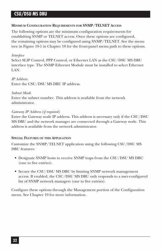
The following options are the minimum configuration requirements forestablishing SNMP or TELNET access. Once these options are configured,the remaining options may be configured using SNMP/TELNET. See the menutree in Figure 10-1 in Chapter 10 for the front-panel menu path to these options.
InterfaceSelect SLIP Control, PPP Control, or Ethernet LAN as the CSU/DSU MS DBUinterface type. The SNMP Ethernet Module must be installed to select EthernetLAN.
IP AddressEnter the CSU/DSU MS DBU IP address.
Subnet MaskEnter the subnet number. This address is available from the networkadministrator.
Gateway IP Address (if required)Enter the Gateway node IP address. This address is necessary only if the CSU/DSUMS DBU and the network manager are connected through a Gateway node. Thisaddress is available from the network administrator.
SPECIAL FEATURES OF THIS APPLICATION
Customize the SNMP/TELNET application using the following CSU/DSU MSDBU features:
• Designate SNMP hosts to receive SNMP traps from the CSU/DSU MS DBU(one to five entries).
• Secure the CSU/DSU MS DBU by limiting SNMP network managementaccess. If enabled, the CSU/DSU MS DBU only responds to a user-configuredlist of SNMP network managers (one to five entries).
Configure these options through the Management portion of the Configurationmenu. See Chapter 10 for more information.

33
CHAPTER 4: Applications
4.2 Dial-Backup ApplicationThe CSU/DSU MS DBU provides point-to-point connection to the network.With one of the DBU module cards installed, the unit is capable of dial backup,allowing the unit to dial around a failed network. See Figure 4-3.
With the DBU options, you can configure the unit to:
• Enter DBU under specific primary network conditions.
• Lock out DBU over the weekend and/or at specified times of the day.
• Dial a specified number when a DBU activation condition is detected.
Figure 4-3. Dial-Backup Application.
ENTERING DIAL-BACKUP MODE
When a condition for entering dial-backup mode is detected, the Alarm LED turnson and the buzzer sounds. The buzzer alternates between 30 seconds on and 30seconds off unless the DDS line is restored or unless it is disabled by using theQuick key and selecting Turn Off Beep. See Figure 3-1 in Chapter 3 for moreinformation on the Quick key.
DDS
SwitchedNetwork
V.34, ISDN, 4-Wire,Switched 56
CSU/DSU MS DBUCSU/DSU MS DBU
DTE DeviceDTE Device

34
CSU/DSU MS DBU
OPERATION DURING CRITICAL TIMES
The following four conditions will cause a CSU/DSU MS DBU to enter dial-backupmode:
Loss of Sealing CurrentSealing current is a low-voltage DC current provided by the central office (CO)to prevent corrosion over the copper wires used in the local loop. Sealing currentmay also be used for local-loop testing purposes. An absence of sealing currentgenerally is an indication that the loop is open.
Out of Service (OOS) SignalAn OOS signal, generated by the network, indicates a device (or devices)in the network is out of service.
No Receive SignalThis is an indication that the copper pairs in the local loop may be either openor shorted, or that the OCU in the CO is inoperative. In a private network,this may indicate that the transmitter of the remote DSU is inoperative.
All-1s or all-0s ConditionThis condition is usually generated by the network to indicate that some device(or devices) in the network is inoperative. Upon detecting an all-1s or all-0scondition, the CSU/DSU MS DBU initiates a handshake routine to determinewhether the remote unit’s DTE is the source of the all-1s or all-0s condition orwhether an actual network failure exists.
Answer AlwaysWhen this option is enabled, the unit goes into DBU mode if a call is presentregardless of the status of the dedicated circuit. It is recommended that theDBU Passcode be used in this mode, since inadvertent calls could stop dataflow indefinitely.
NOTEThe DBU Answer Test is disabled if this option is chosen.
OPERATION DURING NONCRITICAL TIMES
The CSU/DSU MS DBU may be configured not to enter dial-backup mode if DataTerminal Ready (DTR) is low. This feature prevents the CSU/DSU MS DBU fromentering dial backup during noncritical times such as nights and weekends.
For more information, see Chapter 9.

35
CHAPTER 4: Applications
Weekend and Time of Day LockoutThe CSU/DSU MS DBU may be configured not to enter dial-backup modeat certain times of day or on weekends. This protects the customer from beingcharged for a switched call during off hours should the dedicated circuit fail.See Chapter 9 for more information.
CONDITIONS FOR RETURNING TO THE DDS CIRCUIT
The CSU/DSU MS DBU can be configured to automatically revert to the DDScircuit from the dial-backup mode or wait to be returned to the DDS manually.Once the CSU/DSU MS DBU enters dial-backup mode, the unit polls the DDScircuit once every 100 ms to determine if the condition causing the DDS circuitfailure has been corrected. Once the CSU/DSU MS DBU determines that theproblem has been properly corrected and the DDS circuit is stable, it will waitfor the amount of time specified in the restore timer (1 to 255 minutes) beforereverting to the DDS circuit. Polling of the DDS circuit is non-intrusive andreturn to the DDS circuit generally takes 2 to 3 seconds. The backupconnection is maintained for one minute after the DDS circuit is restored.
See Chapter 9 for more detailed information.

36
CSU/DSU MS DBU
5. Configuration OverviewThe CSU/DSU MS DBU contains four different user profiles (sets of configurationoptions) stored in read-only memory; see Appendix D. The unit is shipped fromthe factory with profile number 1 (default configuration) loaded into the current(nonvolatile configuration) memory. If profile 1 matches requirements for thesystem, then no additional configuration is required to put the unit into service.If profile 1 does not match system requirements, it can be modified or one of theother profiles that more closely matches the system requirements can be loadedinto current memory. When a different profile is loaded or the existing profileis modified, it is stored in the current (nonvolatile configuration) memory.The CSU/DSU MS DBU is then configured with that profile every timepower is turned on or the unit is reset.
Configuration MethodsThe CSU/DSU MS DBU responds to the following methods of configuration:
• AT commands
• V.25 commands
• Front-panel commands
• A VT100 compatible terminal
• SNMP/TELNET through a device running SLIP/PPP protocol
• SNMP/TELNET through a LAN running Ethernet protocol (available whenthe SNMP Ethernet Module is installed)
AT and V.25 commands have limited access to configuration parameters. Thecommands are detailed in the following sections of this chapter. See Chapters 2and 3 for more information on all other configuration methods. For an exampleapplication using the SLIP/PPP or Ethernet interface, see Chapter 4.
Descriptions of each Configuration menu item are given in Chapters 6 through 10.
A complete Configuration menu for the front panel is shown in Figure 5-1. TheVT100 menu tree is shown in Appendix C.

37
CHAPTER 5: Configuration Overview
NOTEBecause a VT100 terminal has better display capabilities, the VT100menu structure differs from the front-panel interface. Appendix Cincludes the VT100 screens as well as a complete menu tree foraccessing configuration selections. Descriptions of individual menuoptions are provided throughout this manual based on the front-panelmenu structure. See Figure 5-1 for the front-panel configuration menutree.
COMMANDS
The CSU/DSU MS DBU can be configured and controlled with in-band ATcommands from an asynchronous DTE port just as modems are.
To exit the data mode and enter the command mode, the asynchronous DTEdevice must transmit a proper escape sequence of three pluses (+++) to theCSU/DSU MS DBU. A specified time delay must occur between the last datacharacter and the first escape sequence character. This is the guard-time delay,and it can be changed by writing a value to the S12 register. The default value forthe guard time is one second. For a valid escape sequence to occur, the DTE musttransmit the escape-code character three times in succession with delay betweeneach character being less than the guard time.
Once the command mode is entered, AT commands can be transmitted to theCSU/DSU MS DBU to configure most of the options or initiate tests to checkboth the CSU/DSU MS DBU and the network connections. All command linesmust begin with “AT” in either capital or lower-case letters.
The command line may contain a single command or a series of commands afterthe AT attention code. When a series of commands is used, the individualcommands may be separated by spaces for readability. The maximum length for acommand line is 40 characters. Each command line is executed by the CSU/DSUMS DBU upon receipt of a terminating character. The default terminatingcharacter is a carriage return (ASCII 013), but it can be changed by writing adifferent value to register S3.
Before the terminating character is transmitted, the command line can be editedby using the backspace character (ASCII 008) to erase errors so the propercommands can be entered.
NOTENot all parameters can be selected using these commands. Validcommands are listed in Appendix B.

38
CSU/DSU MS DBU
Figure 5-1. Front-Panel Configuration Menu Tree.
3=CONFIG
1=LOCAL
2=REMOTE ENTER ADDRESS
1=NETWORK OPT.
1=LOOP RATE
2=NETWORK ADDR.
3=REMOTE CONFIG.
4=NETWORK TYPE
5=CLOCK SOURCE
2=DTE OPTIONS
1=AUTO2=2.4K3=4.8K4=9.6K5=19.2K6=38.4K7=56K8=64K
ENTER NETWORKADDRESS:00
1=DISABLED2=ENABLED
1=DEDICATED2=AT&T/MCI SW563=US SPRINT SW56
1=MASTER2=FROM NETWORK
3=TEST OPTIONS
4=DIAL OPTIONS
1=TEST TIMOUT
2-RDL EN/DIS
3=EIA LLB EN/DIS
4=EIA RLB EN/DIS
5=DBU ANS. TEST
ENTER TIMOUT(0=OFF) : 00 SEC
1=RDL IGNORED2=RDL ACCEPTED
1=DISABLED2=ENABLED
1=DISABLED2=ENABLED
1=DISABLED2=ENABLED
5=MANAGEMENT
6=UTILITIES 1=MANUAL COMMAND
2=TIME/DATE
COMMAND: 00
1=CURRENT
2=SET TIME
COMMAND: HHVALUE:00
TIME=23:01:59DATE=08/15/97
1=SET HOURS
2=SET MINUTES
3=SET SECONDS
3=SET DATE 1=SET MONTH
2=SET DAY
3=SET YEAR
3=SOFTWARE REV.
4=LAN MAC ADDR.
VERSIONREV X
CHKSUMXXXX
5=SERIAL NUMBER XXXXXXXXXXXXXXX

39
CHAPTER 5: Configuration Overview
Figure 5-1 (continued). Front-Panel Configuration Menu Tree.
1=DTE RATE
2=CONNECTOR TYPE
3=DATA FORMAT
4=DTE CMD OPTION
5=TRANSMIT CLOCK
6=CS OPTIONS
7=ANTI-STREAM
8=CD OPTIONS
9=TR OPTIONS
A=SR OPTIONS
1=2.4K2=4.8K3=9.6K4=19.2K5=38.4K6=56K/57.6K7=SAME AS LOOP
1=SCRAMBLER OFF2=SCRAMBLER ON3=SUPPRESS LBE
1=EIA 2322=V.35
1=ASYNCHRONOUS2=SYNCHRONOUS
1=ASYNC 9 BITS2=ASYNC 10 BITS3=ASYNC 11 BITS
1=DISABLED2=AT COMMAND SET3=V.25 SYNC4=V.25 BSC/ASYNC
These selections are dependant upon the operation mode (SW56 or DBU). See the chapterConfiguring DTE Options for more information.
1=NORMAL2=EXTERNAL3=INVERT
1=TIMER OFF2=TIME 10 SEC.3=TIME 30 SEC.4=TIME 60 SEC.
1=FORCED ON2=FOLLOWS RS3=FOLLOWS CD
4=FOLLOWS RS+CD5=OFF WITH LOCD
1=FORCED ON2=NORMAL3=OFF WITH LOCD
1=CS DELAY SHORT2=CS DELAY LONG
1-CS DELAY SHORT2=CS DELAY LONG
1=FORCED ON2=OFF OOS ONLY3=OFF LOCD ONLY4=OFF TEST ONLY5=OFF TEST + OOS6=OFF TEST + LOCD
1=INTERFACE
2=CONTROL RATE
1=VT100 CONTROL2=SLIP CONTROL3=PPP CONTROL4=ETHERNET LAN
ENTER CURRENTHOUR (HH):01
ENTER CURRENTMIN (MM):01
ENTER CURRENTSEC. (SS):01
3=IP OPTIONS
4=SNMP OPTIONS
ENTER CURRENTMONTH (MM):01
ENTER CURRENTDAY (DD):07
ENTER CURRENTYEAR (YY):97 5=TELNET OPTIONS
1=GET COMMUNITY2=SET COMMUNITY3=TRAP COMMUNITY4=SNMP TRAPS
5=TRAP IP ADR6=SYS NAME7=SYS CONTACT8=SYS LOCATION9=AUTHEN TRAP
1=TELN PASSWORD
2=TELNET TIMEOUT
1=UNIT IP ADR2=SUBNET MASK3=GATEWAY IP ADR4=IP SECURITY
5=IP FILTER ADDR
1=DISABLE2=GENERIC ONLY3=ENABLE ALL
1=DISABLED2=ENABLED
1=DISABLED2=ENABLED
1=10 MINUTES2=30 MINUTES3=60 MINUTES
ENTER TRAP IPNUMBER (1-5):1
ENTER SOURCE IPNUMBER (1-5):1
1=PHONE NUMBERS
2=SW56 AUTO ANS
3=DBU OPTIONS
4=DBU PASSCODE
1=1200 BPS2=2400 BPS3=9600 BPS
STORED NUMBER TOEDIT (1-10): NNNNNNN
1=DISABLED2=ENABLED
1=DISABLE2=ENABLE
1=ENABLE/DISABLE
2=ENTER CODE XXXX
These selections are dependant upon the DBU card.See the chapter Configuring Dial Options for this portion of the menu tree.

40
CSU/DSU MS DBU
V.25 BIS COMMANDS
When configured for the V.25 bis option, the CSU/DSU MS DBU accepts in-banddialing and configuration commands from both synchronous and asynchronousDTE ports.
The V.25 bis option supports the following protocols:
• SDLC
• Bi-Sync
• Asynchronous
SDLC Option
Character Format• Data bits - 8• Parity bit - Ignored
Command Structure[F][A][C][V.25 bis COMMAND][FCS][F]
The address field [A] is FFH. The control field [C] is set to 13H except for cases ofmulti-frame responses. For this case, the control field is set to 03H in all but the lastframe. The 03H in the control field indicates that other frames are to follow, whilethe 13H in the control field indicates the final frame.
Bi-Sync Option
Character Format• Data bits - 7• Parity bit - Odd
Command Structure[SYN][SYN][STX][V.25 bis COMMAND][ETX]
Asynchronous Option
Character Format• Start bit - 1• Data bits - 7• Parity bit - Even• Stop bit - 1
Command Structure[V.25 bis COMMAND][CR][LF]

41
CHAPTER 5: Configuration Overview
Special V.25 Configuration CommandsIn addition to the CCITT commands supported, Black Box has addedconfiguration commands for both local and remote DSUs:
CNL Configuration local CNR Configuration remote
Possible responses to V.25 bis commands follows:
VALA Valid V.25 command processedINV An invalid command detectedINVCU Unknown command detectedINVPS Invalid parameter syntaxINVPV Invalid parameter valueINVBL Invalid local passwordINVBM Invalid remote password
If verbose responses are disabled (ATV0), the following three-character responsesare the only ones returned:
VAL Valid V.25 command processedINV Invalid command received
Syntax and Possible ResponsesCNL (Configuration Local)This command is used to pass AT commands to the local DSU via the V.25 biscommand processor. This allows the CSU/DSU MS DBU to be configured with ATcommands using a synchronous interface. The format is as follows:
CNL[LOCAL PASSWORD];AT[ONE OR MORE AT COMMANDS]
A local password may not be required depending on the present configuration ofthe unit. Responses to CNL commands are returned in the data format currentlyconfigured. The possible responses are VALA and INVAn.
This command is used to pass AT commands over the network to the remote DSUvia the V.25 bis command processor. This allows a remote CSU/DSU MS DBU tobe configured from a synchronous interface. The format of this command follows:
CNR[REMOTE PASSWORD];AT[ONE OR MORE AT COMMANDS]
The remote password may or may not be required depending on the presentconfiguration of the remote unit. Responses to the CNR commands are returnedin the data format currently configured. Possible responses are VAL and INVAn.

42
CSU/DSU MS DBU
6. Configuring Network OptionsThe Network Options configuration parameters control the loop operation of theCSU/DSU MS DBU. Once a parameter is set, “Command Accepted” is displayedbriefly before returning to the active menu. Table 6-1 shows the AT commandsused to set the Network Options. See Figure 6-1 for the Network Options menutree.
Table 6-1. Network Options AT Commands
Front Panel AT CommandLoop Rate
AUTO %B0
2.4K %B1
4.8K %B2
9.6K %B3
19.2K %B4
38.4K %B5
56K %B6
64K %B7
Network Address
XX (decimal) _N=xx
Remote Configuration
1=DISABLED &P4
2=ENABLED &P5
Network Type
1=DEDICATED none
2=AT&T/MCI® SW56 none
3=US SPRINT® SW56 none
Clock Source
1=MASTER _X0
2=FROM NETWORK _X1

43
CHAPTER 6: Configuring Network Options
Figure 6-1. Network Options Menu Tree.
6.1 Loop RateThe Loop Rate option sets the loop operating speed. The unit should be setto the rate required by the DDS service. The CSU/DSU MS DBU also supportssubrate DTE data over a 56-kbps or 64-kbps loop. The loop rate must be setindependently of the DTE rate. Eight loop-rate selections are available(shown in Figure 6-1).
The default factory setting is Auto. The various loop rates and format selectionsare listed in Table 6-1 with the equivalent AT commands that perform the sameconfiguration functions.
6.2 Network AddressA two-digit decimal address can be assigned to each CSU/DSU MS DBU.This addressing capability makes it possible to perform remote configurationand testing in point-to-point and multi-drop networks. Figure 6-1 shows themenu path used to change the network address. The factory default setting is 0.
3=CONFIG
1=LOCAL
2=REMOTE ENTER ADDRESS
1=NETWORK OPT.
2=DTE OPTIONS3=TEST OPTIONS4=DIAL OPTIONS5=MANAGEMENT6=UTILITIES
1=LOOP RATE
2=NETWORK ADDR.
3=REMOTE CONFIG.
4=NETWORK TYPE
5=CLOCK SOURCE
1=AUTO2=2.4K3=4.8K4=9.6K5=19.2K6=38.4K7=56K8=64K
ENTER NETWORKADDRESS:00
1=DISABLED2=ENABLED
1=DEDICATED2=AT&T/MCI SW563=US SPRINT SW56
1=MASTER2=FROM NETWORK

44
CSU/DSU MS DBU
6.3 Remote ConfigurationThis option sets up the CSU/DSU MS DBU to accept or reject remoteconfiguration commands. The factory-default setting is Enabled.
CAUTIONAny type of remote configuration disrupts data flow.
6.4 Network TypeSelect the appropriate network type. The choices are dedicated, AT&T/MCISW56, and US Sprint SW56.
6.5 Clock SourceThe Clock Source option specifies the timing source for the CSU/DSU MS DBU’sinternal circuitry. The factory-default setting is From Network.
When operating on a DDS network, the timing should be From Network. On apoint-to-point private network, one CSU/DSU MS DBU must be set for Master,the other set for From Network.

45
CHAPTER 7: Configuring DTE Options
7. Configuring DTE OptionsThe DTE Options menu is used to select the configuration parameters that controlthe operation of the DTE Interface of the CSU/DSU MS DBU. The DTE Optionsmenu tree is shown in Figure 7-1. Table 7-1 shows the available options and theirAT commands.
Figure 7-1. DTE Options Menu Tree.
3=CONFIG
1=LOCAL
2=REMOTE ENTER ADDRESS
1=NETWORK OPT.2=DTE OPTIONS3=TEST OPTIONS4=DIAL OPTIONS5=MANAGEMENT6=UTILITIES
1=DTE RATE
2=CONNECTOR TYPE
3=DATA FORMAT
4=DTE CMD OPTION
5=TRANSMIT CLOCK
6=CS OPTIONS
7=ANTI-STREAM
8=CD OPTIONS
9=TR OPTIONS
A=SR OPTIONS
1=2.4K2=4.8K3=9.6K4=19.2K5=38.4K6=56K/57.6K7=SAME AS LOOP
1=EIA 2322=V.35
1=ASYNCHRONOUS2=SYNCHRONOUS
1=DISABLED2=AT COMMAND SET3=V.25 SYNC4=V.25 BSC/ASYNC
1=FORCED ON2=FOLLOWS RS3=FOLLOWS CD
4=FOLLOWS RS+CD5=OFF WITH LOCD
1=TIMER OFF2=TIME 10 SEC.3=TIME 30 SEC.4=TIME 60 SEC.
1=SCRAMBLER OFF2=SCRAMBLER ON3=SUPPRESS LBE
1=ASYNC 9 BITS2=ASYNC 10 BITS3=ASYNC 11 BITS
1=NORMAL2=EXTERNAL3=INVERT
1=CS DELAY SHORT2=CS DELAY LONG
1=CS DELAY SHORT2=CS DELAY LONG
1=FORCED ON2=NORMAL3=OFF WITH LOCD
1=FORCED ON2=OFF OOS ONLY3=OFF LOCD ONLY4=OFF TEST ONLY5=OFF TEST + OOS6=OFF TEST + LOCD
1=IGNORED2=IDLE WHEN OFF3=OFF>ON DIAL #14=OFF>ON DIAL #25=NO DBU IF OFF

46
CSU/DSU MS DBU
Table 7-1. DTE Options AT Commands
Front Panel AT DescriptionCommand
DTE Rate
1=2.4K %K3 DTE rate: 2.4K sync and async
2=4.8K %K4 DTE rate: 4.8K sync and async
3=9.6K %K5 DTE rate: 9.6K sync and async
4=19.2K %K6 DTE rate: 19.2K sync and async
5=38.4K %K7 DTE rate: 38.4K sync and async
6=56K/57.6K %K8 DTE rate: 56K sync or 57.6K async
7=SAME AS LOOP %K9 DTE rate matches loop rate
1=SCRAMBLER OFF _F0 DTE data scrambler disabled (64-kbps loop
rate only)
2=SCRAMBLER ON _F1 DTE data scrambler enabled (64-kbps loop
rate only)
3=SUPPRESS LBE _F2 Suppresses loopback-enable code (LBE) in
transmit data from the DTE after 30 bytes in
a row detected (64-kbps loop rate only)
Data Format
1=ASYNCHRONOUS &Q0 Asynchronous DTE operation mode
2=SYNCHRONOUS &Q2 Synchronous DTE operation mode
DTE CMD Option
1=DISABLED none Disables all DTE command modes
2=AT COMMAND SET none Enables AT command mode for DTE
3=V.25 SYNC none Enables V.25 (SDLC) command mode for
DTE
4=V.25 BSC/ASYNC none Enables V.25 (bisync or async) command
mode for DTE
Transmit Clock
1=NORMAL &X0 TX clock from DSU selected
2=EXTERNAL &X1 ETC clock from DTE selected
3=INVERT &X3 Inverted Tx clock from DSU selected
CS Options
1=FORCED ON &R0 CS always on
2=FOLLOWS RS &R1 CS state same as RS state
3=FOLLOWS CD &R2 CS state same as CD state
4=FOLLOWS RS+CD &R3 CS state same as RS and CD state

47
CHAPTER 7: Configuring DTE Options
Table 7-1 (continued). DTE Options AT Commands
Front Panel AT DescriptionCommand
CS Options (continued)
5=OFF WITH LOCD &R4 Off 5 sec after LOCD (SW56 only)
For Follows RS options, select the length of the delay.
1=CS DELAY SHORT _D0 Short delay from RS to CS selected
2=CS DELAY LONG _D1 Long delay from RS to CS selected
Anti-Stream
1=TIMER OFF %T0 Anti-stream timer disabled
2=TIME 10 SEC. %T1 Timeout equals 10 seconds
3=TIME 30 SEC. %T2 Timeout equals 30 seconds
4=TIME 60 SEC. %T3 Timeout equals 60 seconds
CD Options
1=FORCED ON &C0 On all the time
2=NORMAL &C1 On only when data present on loop
3=OFF WITH LOCD &C2 On except after disconnect (SW56 only)
TR Options
1=IGNORED &D0 Ignore the TR input
2=IDLE WHEN OFF &D2 See the note on the next page.
3=OFF>ON DIAL #1 &D3 Dial Stored #1: TR goes off to on (SW56
only)
4=OFF >ON DIAL #2 &D4 Dial Stored #2: TR goes off to on (SW56
only)
5=NO DBU IF OFF &D3 No dial backup if TR is off.
(valid only when DBU
module is installed and
Network Type is set to
DEDICATED)
SR Options
1=FORCED ON &S0_C1 Always on
2=OFF OOS ONLY &S1_C1 Off when network out of service
3=OFF LOCD ONLY &S3 Off 5 sec after disconnect (SW56 only)
4=OFF TEST ONLY &S0_C0 Off for test only
5=OFF TEST+OOS &S1_C0 Off for test and OOS
6=OFF TEST + LOCD &S5 Off 5 sec after disconnect or test.

48
CSU/DSU MS DBU
NOTEFor IDLE WHEN OFF option: In SW56 mode, TR off causes the DSU to goOn Hook (Idle). The unit does not dial out if TR is off. In dedicated mode,the DSU goes into DTE command mode when TR goes off. When TRgoes on, if the DSU does not receive a command in the number ofseconds set in S40, the DSU goes into data mode.
7.1 DTE RateIf a DTE rate higher than the current loop rate is selected, the DTE rateautomatically set to match the slower loop rate; the CSU/DSU MS DBU brieflydisplays DTE RATE SAME AS THE NETWORK before returning to the statusscreen. The factory-default setting is SAME AS LOOP.
If the CSU/DSU MS DBU is set for a loop rate of 64 kbps, then scrambleron/off options are available. The factory-default setting is Scrambler Off.
CAUTIONFor 64-kbps clear-channel operation, the DTE data sequences mightmimic network loop-maintenance functions and erroneously causeother network elements to activate loopbacks. To prevents this, theScrambler On option should be selected for both the local and remoteCSU/DSU MS DBU.
7.2 Connector TypeThe Connector Type option is used to specify which of the primary channelconnectors is used to connect to the DTE. The factory-default setting is V.35.There are no AT commands available to set the connector type.
7.3 Data FormatThe Data Format option is used to select either the synchronous or asynchronousmode of operation for the DTE interface. The factory-default setting isSynchronous. If asynchronous is chosen, the length of the data bytes must beselected.
Table 7-1 shows the AT commands that can be used to set the Data Format toasynchronous or synchronous.
49
CHAPTER 7: Configuring DTE Options
7.4 DTE Command OptionThe DTE Command option is used to enable a DTE command mode or disableall modes. The available modes are AT, V.25 synchronous, and V.25bisynchronous/asynchronous commands.
7.5 Transmit ClockThe Transmit clock option is used to select the source of the clock used to transferdata from the DTE into the CSU/DSU MS DBU. Table 7-1 shows the ATcommands used to set the Transmit Clock options.
The External clock option is normally used in modem tail-circuit applications.A DSU-to-modem interconnect diagram for this application is shown in AppendixE. The External clock option is also recommended when the EIA-232 connectoris used for 56-kbps and 64-kbps applications. Using this option eliminates dataerrors caused by excessive delays in the DTE transmit clock receiver andtransmit data driver.
The Invert clock option is recommended when the EIA-232 connectoris used for rates other than 56 kbps or 64 kbps.
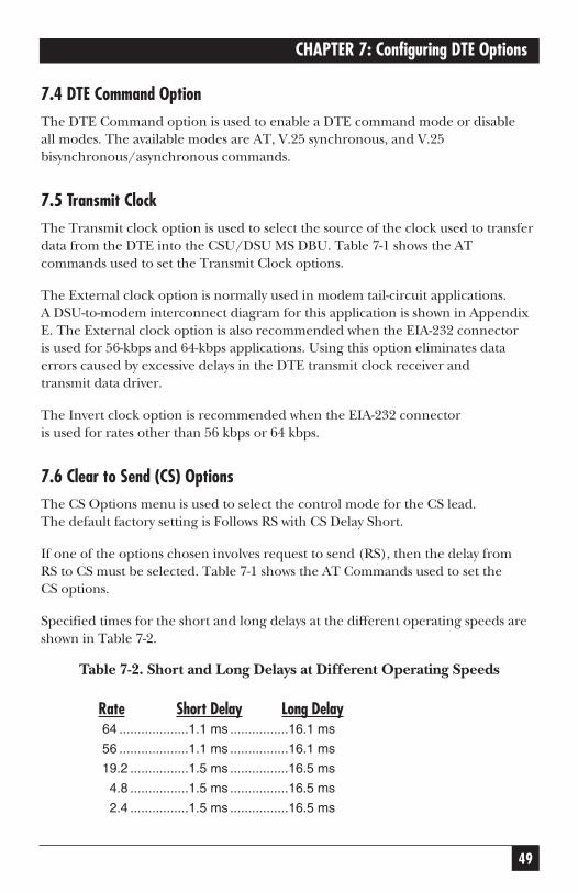
7.6 Clear to Send (CS) OptionsThe CS Options menu is used to select the control mode for the CS lead.The default factory setting is Follows RS with CS Delay Short.
If one of the options chosen involves request to send (RS), then the delay fromRS to CS must be selected. Table 7-1 shows the AT Commands used to set theCS options.
Specified times for the short and long delays at the different operating speeds areshown in Table 7-2.
Table 7-2. Short and Long Delays at Different Operating Speeds
Rate Short Delay Long Delay64 ...................1.1 ms ................16.1 ms
56 ...................1.1 ms ................16.1 ms
19.2 ................1.5 ms ................16.5 ms
4.8 ................1.5 ms ................16.5 ms
2.4 ................1.5 ms ................16.5 ms

50
CSU/DSU MS DBU
7.7 Anti-StreamThe Anti-Stream option is used to select the anti-stream timeout. The anti-streamtimeout is the maximum time the CSU/DSU MS DBU transmits data into thenetwork from the DTE. This feature prevents one DTE device on a multi-dropnetwork from continuously tying up the transmit circuit back to the master DSU.
The anti-stream timer is reset to zero when RS changes to the active state and isupdated every second while RS is active. When the anti-stream timeout expires,the CSU/DSU MS DBU stops transmitting DTE data into the network butcontinues to accept data from it. This condition exists until the DTEdeactivates the RS input.
The factory-default setting is Timer Off. Table 7-1 shows the available optionsand their AT commands.
7.8 CD OptionsThe CD Options menu is used to select the control mode for the receiveline signal detector (CD) lead. The factory-default setting is Normal. Table 7-1 shows the equivalent AT commands for setting CD options.
7.9 Data Terminal Ready (TR) OptionsThe TR Options menu is used to select the CSU/DSU MS DBU responseto the Data Terminal Ready (TR) lead. The factory-default setting is Ignored.Table 7-1 shows the equivalent AT commands for setting TR options.
NOTEThe NO DBU IF OFF selection is available only when a DBU module is installed and the Network Type is set to DEDICATED.
To disable DBU when DTR is off, set this option for IDLE WHEN OFF.
7.10 Data Set Ready (SR) OptionsThe SR Options menu is used to select the operating mode for the Data Set Ready (SR) lead. Use Shift + A to activate the SR Options submenu; press Enter to enter the SR Options submenu. The factory-default settingis Off Test Only. Table 7-1 shows the AT commands for setting SR options.

51
CHAPTER 8: Configuring Test Options
8. Configuring Test OptionsThe Test Options menu enables or disables different test modes and specifiesthe maximum test time allowed. See Figure 8-1 for the Test Options menu tree.The available options and their AT commands are listed in Table 8-1.
Figure 8-1. Test Options Menu Tree.
3=CONFIG
1=LOCAL
2=REMOTE ENTER ADDRESS
1=NETWORK OPT.2=DTE OPTIONS3=TEST OPTIONS4=DIAL OPTIONS5=MANAGEMENT6=UTILITIES
1=TEST TIMEOUT
2=RDL EN/DIS
3=EIA LLB EN/DIS
4=EIA RLB EN/DIS
5=DBU ANS. TEST
1=DISABLED2=ENABLED
1=DISABLED2=ENABLED
1=DISABLED2=ENABLED
ENTER TIMEOUT(0=OFF) : 00 SEC
1=RDL IGNORED2=RDL ACCEPTED

52
CSU/DSU MS DBU
Table 8-1. Test Options AT Commands
Front Panel AT Command DescriptionTest Timeout
ENTER TIMEOUT S18=x Specify 0-255 second test timeout
RDL Enable/Disable
1=RDL IGNORED &T5 RDL request from remote DSU ignored
2=RDL ACCEPTED &T4 RDL request accepted
EIA LLB Enable/Disable
1=DISABLED _A0 No response to local loopback
2=ENABLED _A1 Responds to local loopback
EIA RLB Enable/Disable
1=DISABLED _R0 No response to remote loopback
2=ENABLED _R1 Responds to remote loopback
DBU Answer Test
1=DISABLED none Remote unit does not accept DBU
tests from far end
2=ENABLED none Remote unit accepts DBU tests from
far end
TEST TIMEOUT
The Test Timeout option sets the length of time a CSU/DSU MS DBU remains ina test mode before automatically returning to the data mode. Enter the timeout asa two-digit decimal value. The factory-default setting is off (0).
REMOTE DIGITAL LOOPBACK (RDL)
The RDL option specifies whether the CSU/DSU MS DBU responds to an RDLrequest from the far end of the circuit. The factory-default setting is RDLAccepted.
EIA LLB
The EIA LLB (Electronics Industries Association local loopback) option specifieswhether the CSU/DSU MS DBU responds to the local loopback input from theDTE. The factory-default setting is Disabled.
EIA RLB
The EIA RLB (remote loopback) option specifies whether the CSU/DSU MS DBUresponds to the RLB input from the DTE. The factory-default setting is Disabled.

53
CHAPTER 8: Configuring Test Options
DBU ANSWER TEST
The dial-backup connection can be tested while data is passing on the DDS.In order for this test to be performed, DBU Answer Test must be enabled onthe remote unit. If DBU Answer Test is not enabled, the remote unit will notaccept a DBU test from the other end. The factory-default setting is Disabled.
NOTEThe DBU Answer Test is not available if the DBU Criteria option “AnswerAlways” is Enabled.

54
CSU/DSU MS DBU
9. Configuring Dial OptionsThe Dial Options menu stores up to ten phone numbers, enables/disables theSW56 auto answer capability, defines the dial-backup operation when the DDScircuit fails, and programs the passcode security feature.
Figure 9-1 shows the full Dial Backup Options (4=Dial Options) menu.Note that some items are restricted to certain DBU cards.
Figure 9-1. Dial Options Configuration Menu Tree.
3=CONFIG
1=NETWORK OPT.2=DTE OPTIONS3=TEST OPTIONS4=DIAL OPTIONS5=MANAGEMENT6=UTILITIES
1=PHONE NUMBERS
2=SW56 AUTO ANS
3=DBU OPTIONS
4=DBU PASSCODE
STORED NUMBER TOEDIT (1-10):
1=DISABLED2=ENABLED
NNNNNNN
1=AUTOMATIC DBU
2=NUMBER TO DIAL
3=ORIGIN/ANSWER
4=DBU CRITERIA
5=AUTO RESTORE
1=DISABLED2=ENABLED
1=DBU ORIGINATE2=DBU ANSWER
RESTORE TIMER(0=OFF): 0 MIN
6=REDIAL COUNTER
7=FAIL TIMER
8=WAIT TO REDIAL
ENTER REDIALCOUNT: 0
AUTO DBU FAILTIME: 0X10 SEC
WAIT TO REDIALTIME: 0 SEC
9=NETWORK TYPE 1=AT&T/MCI/OTHER2=US SPRINT
9=ERROR CONTROL 1=BUFFERED2=DIRECT3=RELIABLE MNP4=AUTO MNP5=RELIABLE V.426=REL. V.42/MNP7=AUTO V.42/MNP
A=FLOW CONTROL 1=DISABLED2=XON/XOFF3=CTS ONLY4=RTS/CTS5=UNI. XON/OFF
B=COMPRESSION 1=DISABLED2=ENABLED
9=SWITCH TYPE1=AT&T 5ESS2=NT DMS-1003=NATIONAL ISDN 1=ENABLE/DISABLE 1=DISABLED
2=ENABLED
2=ENTER CODE XXXX
1=DBU WITH #12=DBU WITH #2
1=WHEN OOS
2=NO RX SIGNAL
3=NO SEAL CUR.
4=WHEN ALL 1s/0s
5=ANSWER ALWAYS
6=WEEKEND LCKOUT
1=DISABLED2=ENABLED
1=DISABLED2=ENABLED
1=DISABLED2=ENABLED
1=DISABLED2=ENABLED
1=DISABLED2=ENABLED
1=DISABLED2=ENABLED
1=DISABLED2=ENABLED
7=DAILY LCKOUT
8=LOCKOUT START
9=LOCKOUT END
LOCKOUT STARTHR (0-23): xx
LOCKOUT ENDHR (0-23): xx
SW4 DBU Option CardSW4 DBU Option Card
VV.34 DBU Option Card.34 DBU Option Card
ISDN DBU Option CardISDN DBU Option Card
55
CHAPTER 9: Configuring Dial Options
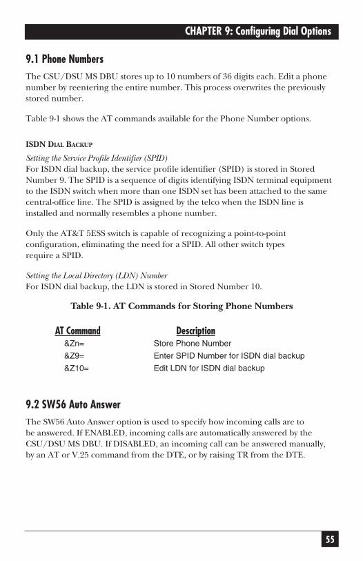
9.1 Phone NumbersThe CSU/DSU MS DBU stores up to 10 numbers of 36 digits each. Edit a phonenumber by reentering the entire number. This process overwrites the previouslystored number.
Table 9-1 shows the AT commands available for the Phone Number options.
ISDN DIAL BACKUP
Setting the Service Profile Identifier (SPID)For ISDN dial backup, the service profile identifier (SPID) is stored in StoredNumber 9. The SPID is a sequence of digits identifying ISDN terminal equipmentto the ISDN switch when more than one ISDN set has been attached to the samecentral-office line. The SPID is assigned by the telco when the ISDN line isinstalled and normally resembles a phone number.
Only the AT&T 5ESS switch is capable of recognizing a point-to-pointconfiguration, eliminating the need for a SPID. All other switch typesrequire a SPID.
Setting the Local Directory (LDN) NumberFor ISDN dial backup, the LDN is stored in Stored Number 10.
Table 9-1. AT Commands for Storing Phone Numbers
AT Command Description&Zn= Store Phone Number
&Z9= Enter SPID Number for ISDN dial backup
&Z10= Edit LDN for ISDN dial backup
9.2 SW56 Auto AnswerThe SW56 Auto Answer option is used to specify how incoming calls are tobe answered. If ENABLED, incoming calls are automatically answered by theCSU/DSU MS DBU. If DISABLED, an incoming call can be answered manually,by an AT or V.25 command from the DTE, or by raising TR from the DTE.

56
CSU/DSU MS DBU
9.3 DBU OptionsThe DBU Options are used to select the modes of operation for the Dial Backupfeatures. There are ten standard options available with additional options forspecific backup services. Table 9-2 lists the DBU options and their AT commandsfor all models.
9.3.1 STANDARD DBU OPTIONS
Automatic DBUThe Automatic DBU option specifies whether the unit automatically enters dial-backup mode or waits for manual setup. The factory-default setting is Disabled.
Number to DialThe Number to Dial option offers a selection of stored numbers for the unit toautomatically dial. If the leased line fails, and the CSU/DSU MS DBU is set tooriginate, it dials the numbers (first #1, then #2) specified under this optionto set up the dial-backup line. The factory-default setting is Dial With #1.
Originate/AnswerThis option specifies whether the CSU/DSU MS DBU originates or waits to answerif the dedicated circuit fails. One end must be set to Originate and the other toAnswer. The factory-default setting is Answer.
DBU CriteriaThese options specify the conditions that will cause the CSU/DSU MS DBUto enter the backup mode.
When Out of Service (OOS): When enabled, the CSU/DSU MS DBU entersbackup mode if an out-of-service condition is detected. The factory-defaultsetting is Enable.
No Receive (RX) Signal: When enabled, the CSU/DSU MS DBU enters backupmode when a loss of signal is detected. The factory-default setting is Enable.
No Sealing Current: When enabled, the CSU/DSU MS DBU enters backup modewhen a loss of sealing current is detected. The factory-default setting is Enable.
When all 1s/0s: When this option is enabled, the CSU/DSU MS DBU monitorsthe receive data for strings of 1s or 0s that are longer than the Fail Timer. If thiscondition is detected, the local CSU/DSU MS DBU initiates a handshake routinewith the remote unit to determine if the DTE is generating the constant datapattern or if the network has failed.
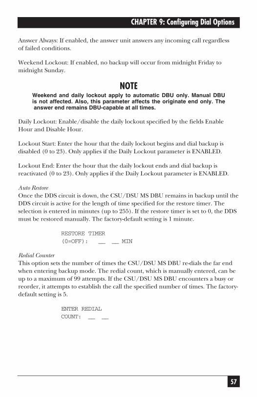
57
CHAPTER 9: Configuring Dial Options
Answer Always: If enabled, the answer unit answers any incoming call regardlessof failed conditions.
Weekend Lockout: If enabled, no backup will occur from midnight Friday tomidnight Sunday.
NOTEWeekend and daily lockout apply to automatic DBU only. Manual DBUis not affected. Also, this parameter affects the originate end only. Theanswer end remains DBU-capable at all times.
Daily Lockout: Enable/disable the daily lockout specified by the fields EnableHour and Disable Hour.
Lockout Start: Enter the hour that the daily lockout begins and dial backup isdisabled (0 to 23). Only applies if the Daily Lockout parameter is ENABLED.
Lockout End: Enter the hour that the daily lockout ends and dial backup isreactivated (0 to 23). Only applies if the Daily Lockout parameter is ENABLED.
Auto RestoreOnce the DDS circuit is down, the CSU/DSU MS DBU remains in backup until theDDS circuit is active for the length of time specified for the restore timer. Theselection is entered in minutes (up to 255). If the restore timer is set to 0, the DDSmust be restored manually. The factory-default setting is 1 minute.
RESTORE TIMER(0=OFF): __ __ MIN
Redial CounterThis option sets the number of times the CSU/DSU MS DBU re-dials the far endwhen entering backup mode. The redial count, which is manually entered, can beup to a maximum of 99 attempts. If the CSU/DSU MS DBU encounters a busy orreorder, it attempts to establish the call the specified number of times. The factory-default setting is 5.
ENTER REDIALCOUNT: __ __
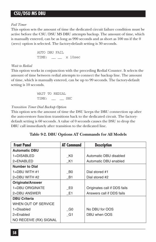
58
CSU/DSU MS DBU
Fail TimerThis option sets the amount of time the dedicated circuit failure condition must beactive before the CSU/DSU MS DBU attempts backup. The amount of time, whichis manually entered, can be as long as 990 seconds and as short as 100 ms if the 0(zero) option is selected. The factory-default setting is 30 seconds.
AUTO DBU FAILTIME: __ __ x 10sec
Wait to RedialThis option works in conjunction with the preceding Redial Counter. It selects theamount of time between redial attempts to connect the backup line. The amountof time, which is manually entered, can be up to 99 seconds. The factory-defaultsetting is 10 seconds.
WAIT TO REDIALTIME: __ __ SEC
Transition Timer Dial Backup OptionThis option sets the amount of time the DSU keeps the DBU connection up afterthe auto-restore function transitions back to the dedicated circuit. The factory-default setting is 60 seconds. A value of 0 seconds causes the DSU to drop theDBU call immediately after transition to the dedicated line.
Table 9-2. DBU Options AT Commands for All Models
Front Panel AT Command DescriptionAutomatic DBU
1=DISABLED _K0 Automatic DBU disabled
2=ENABLED _K1 Automatic DBU enabled
Number to Dial
1=DBU WITH #1 _B0 Dial stored #1
2=DBU WITH #2 _B1 Dial stored #2
Originate/Answer
1=DBU ORIGINATE _E0 Originates call if DDS fails
2=DBU ANSWER _E1 Answers call if DDS fails
DBU Criteria
WHEN OUT OF SERVICE
1=Disabled _G0 No DBU for OOS
2=Enabled _G1 DBU when OOS
NO RECEIVE (RX) SIGNAL
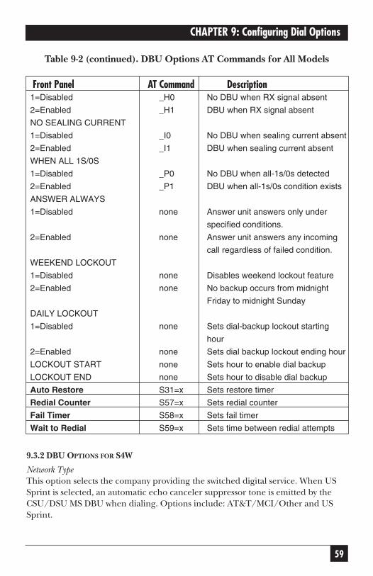
59
CHAPTER 9: Configuring Dial Options
Table 9-2 (continued). DBU Options AT Commands for All Models
Front Panel AT Command Description1=Disabled _H0 No DBU when RX signal absent
2=Enabled _H1 DBU when RX signal absent
NO SEALING CURRENT
1=Disabled _I0 No DBU when sealing current absent
2=Enabled _I1 DBU when sealing current absent
WHEN ALL 1S/0S
1=Disabled _P0 No DBU when all-1s/0s detected
2=Enabled _P1 DBU when all-1s/0s condition exists
ANSWER ALWAYS
1=Disabled none Answer unit answers only under
specified conditions.
2=Enabled none Answer unit answers any incoming
call regardless of failed condition.
WEEKEND LOCKOUT
1=Disabled none Disables weekend lockout feature
2=Enabled none No backup occurs from midnight
Friday to midnight Sunday
DAILY LOCKOUT
1=Disabled none Sets dial-backup lockout starting
hour
2=Enabled none Sets dial backup lockout ending hour
LOCKOUT START none Sets hour to enable dial backup
LOCKOUT END none Sets hour to disable dial backup
Auto Restore S31=x Sets restore timer
Redial Counter S57=x Sets redial counter
Fail Timer S58=x Sets fail timer
Wait to Redial S59=x Sets time between redial attempts
9.3.2 DBU OPTIONS FOR S4W
Network TypeThis option selects the company providing the switched digital service. When USSprint is selected, an automatic echo canceler suppressor tone is emitted by theCSU/DSU MS DBU when dialing. Options include: AT&T/MCI/Other and USSprint.

60
CSU/DSU MS DBU
9.3.3 DBU OPTIONS FOR V.34 CARD
Table 9-3 shows the equivalent AT commands for setting Error Control,Flow Control, and Compression options.
Error ControlThis option determines the type of error control to be negotiated at the startof a V.34 modem connection. The factory-default setting is AUTO V.42/MNP.
Flow ControlThis option is used to select the type of flow control used by the V.34 modem.The factory-default setting is CTS Only.
CompressionThis option is used to select V.42 bis data compression for V.32 bis or V.34operation when running asynchronously. When compression is enabled, data-throughput speeds as high as 57.6 kbps may be achieved. For synchronousapplications, the speed is limited to a maximum of 33.6 kbps for the V.34 Card.The factory-default setting is Enabled.
Table 9-3. DBU Options AT Commands for V.34 Card
DBU Options CMD AT DescriptionError Control
1=BUFFERED \N0 Normal operation. No error control. Allows
speed matching, buffering, and flow control.
2=DIRECT \N1 Direct operation. No error control, no buffer,
and no flow control.
3=RELIABLE MNP \N2 Reliable MNP operation. Uses MNP® error
control.
4=AUTO MNP \N3 Auto-Reliable MNP operation. Tries MNP
error control first; uses normal operation if
necessary.
5=RELIABLE V.42 \N4 Reliable V.42 (LAPM) operation. Uses V.42
(LAPM) error control. If V.42 (LAPM) error
control cannot be used, the call is
disconnected.
6=REL. V.42/MNP \N5 Reliable V.42 (LAPM) or MNP operation.
Uses either V.42 (LAPM) or MNP error
control. If neither can be used, the call is
disconnected.

61
CHAPTER 9: Configuring Dial Options
Table 9-3 (continued). DBU Options AT Commands for V.34 Card
DBU Options CMD AT DescriptionError Control
7=AUTO V.42/MNP \N6 Auto-Reliable V.42 (LAPM) or MNP operation.
Tries to use V.42 (LAPM) error control first,
and MNP error control next. If neither can be
used, then Normal operation is used.
Flow Control
1=DISABLED \Q0 Flow control disabled
2=XON/XOFF \Q1 Enables XOn/XOff flow control
3=CTS ONLY \Q2 Enables CTS flow control from DCE
4=RTS/CTS \Q3 Enables CTS flow control from DCE and
RTS from DTE
5=UNI XON/XOFF \Q4 Unidirectional X-ON/X-OFF
Compression
1=DISABLED %C0 Compression disabled
2=ENABLED %C1 Compression enabled
9.3.4 DBU OPTIONS FOR ISDN CARD
SWITCH TYPE
This option selects the type of telco CO switch providing the ISDN service.There are three options for ISDN switch types:
• AT&T 5ESS
• NT DMS-100
• National ISDN
9.3.5 DBU PASSCODE
The dial-backup passcode adds an additional level of security to the CSU/DSU MSDBU. A passcode of one to ten characters can be programmed into the unit.
When a dial-backup connection is established, the originate unit transmits a pre-programmed passcode to the answer unit over the dial-backup connection beforethe connection is considered valid. The answer unit compares the receivedpasscode to a pre-programmed passcode. If the passcode matches, the receive unitsends a Passcode OK message to the originate unit and goes on-line. If the

62
CSU/DSU MS DBU
passcode does not match, the answer unit sends an Invalid Passcode message tothe originate unit and terminates the dial-backup connection. If a passcode is notreceived by an answer unit with passcode enable, or if the Passcode OK messageis not received by an originate unit with passcode enabled, the dial-backupconnection is terminated.

63
CHAPTER 10: Configuring Management Functions
10. Configuring ManagementFunctions
The Management menu is used to select the desired management interfacetype and to set up the necessary parameters for establishing TELNET orSNMP management. See Figure 10-1 for the Management menu tree.
Figure 10-1. Management Menu Tree.
10.1 InterfaceSelect the management interface type (VT100 terminal, SLIP, or PPP) or selectEthernet LAN (the SNMP Ethernet Module must be installed).
10.2 Control RateSelect the control port operating speed to match the connected device (thisselection only applies when the interface options is set for VT100 terminal, SLIP,or PPP).
3=CONFIG
1=LOCAL
2=REMOTE ENTER ADDRESS
1=NETWORK OPT.2=DTE OPTIONS3=TEST OPTIONS4=DIAL OPTIONS5=MANAGEMENT6=UTILITIES
1=INTERFACE
2=CONTROL RATE
3=IP OPTIONS
4=SNMP OPTIONS
5=TELNET OPTIONS 1=TELN PASSWORD2=TELNET TIMEOUT
1=VT 100 CONTROL2=SLIP CONTROL3=PPP CONTROL4=ETHERNET LAN
1=1200 BPS2=2400 BPS3=9600 BPS
1=UNIT IP ADR2=SUBNET MASK3=GATEWAY IP ADR4=IP SECURITY
5=IP FILTER ADDR
1=GET COMMUNITY2=SET COMMUNITY3=TRAP COMMUNITY4=SNMP TRAPS
5=TRAP IP ADR6=SYS NAME7=SYS CONTACT8=SYS LOCATION9=AUTHEN TRAPS
1=DISABLED2=ENABLED
ENTER SOURCE IPNUMBER (1-5): 1
1=DISABLE2=GENERIC ONLY3=ENABLE ALL
ENTER TRAP IPNUMBER (1-5): 1
1=DISABLED2=ENABLED
1=10 MINUTES2=30 MINUTES3=60 MINUTES

64
CSU/DSU MS DBU
10.3 IP Options
NOTEWhen configuring the CSU/DSU MS DBU with the front panel, use the “*”key to enter a decimal point.
10.3.1 UNIT IP ADDRESS
Enter the CSU/DSU MS DBU IP address in dotted decimal notation.
10.3.2 SUBNET MASK
Enter the subnet number in dotted decimal notation. This address is availablefrom the network administrator.
10.3.3 GATEWAY IP ADDRESS
Enter the Gateway node IP address in dotted decimal notation. This address isnecessary only if the CSU/DSU MS DBU and network manager are connectedthrough a Gateway node. If an IP packet with an unknown IP address is received,the CSU/DSU MS DBU sends it to the Gateway.
10.3.4 IP SECURITY
Enable/disable the IP security option. If enabled, the CSU/DSU MS DBU onlyaccepts management commands from the IP addresses (up to 5) entered intothe IP Filter Address field.
10.3.5 IP FILTER ADDRESS
Enter the IP addresses of the management stations from which the CSU/DSU MSDBU should accept management commands. This filter must be enabled thoughthe IP Security field.

65
CHAPTER 10: Configuring Management Functions
10.4 SNMP OptionsThe following options must be configured when SNMP management is used.
GET COMMUNITY
For SNMP operation, view and edit the Get community string. The CSU/DSU MSDBU uses this string to validate SNMP Get (read) requests. The default value ispublic. If using front-panel entry, see Section 10.6 for more information.
SET COMMUNITY
For SNMP operation, view and edit the Set community string. The CSU/DSU MSDBU uses this string to validate SNMP Set (write) requests. The default value isprivate. If using front-panel entry, see Section 10.6 for more information.
TRAP COMMUNITY
For SNMP operation, view and edit the Trap community string. The CSU/DSU MSDBU sends this string in SNMP trap messages to the network manager. The defaultvalue is “MT136A”. If using front-panel entry, see Section 10.6 for moreinformation.
SNMP TRAPS
Specify which traps the CSU/DSU MS DBU will send to the network manager.When enabled, the CSU/DSU MS DBU sends SNMP traps to network managersfor alarm conditions. The options are DISABLE, GENERIC ONLY, and ENABLEALL. The GENERIC ONLY option enables the Generic Standard traps specified inthe SNMP standard, RFC 1157. The ALL option sends both Generic Standard trapsand the enterprise-specific traps specified in the Black Box CSU/DSU MS DBUMIB.
TRAP IP ADDRESS
Enter up to five IP addresses of the SNMP managers to which the CSU/DSU MSDBU should send traps.
SYSTEM NAME, CONTACT, AND LOCATION
These data fields are general information strings (defined in MIB-II standard, RFC1213) which can be stored by the user and retrieved by the SNMP managementstation. If using front-panel entry, see Section 10.6 for more information.

66
CSU/DSU MS DBU
AUTHENTICATION TRAPS
Enable/disable the CSU/DSU MS DBU to send SNMP authentication traps tothe SNMP management station. If enabled, the CSU/DSU MS DBU sends thesetraps when an SNMP request with an invalid community name string is received.
NOTEThe Black Box CSU/DSU MS DBU MIB is available in the support sectionof the Black Box Web page at www.blackbox.com.
10.5 TELNET Options
TELNET PASSWORD
View/edit the TELNET password. If using front-panel entry, see Section 10.6 formore information.
TELNET TIMEOUT
Select the inactivity time limit. If the unit is idle for the designated amount of timethe unit times out, closing the TELNET session.
10.6 Entering Letters Using the Front PanelSome Management menus require the entry of letters rather than numbers. Whenconfiguring the unit using the front panel, special steps must be taken in order toperform these entries. The following example of entering the TELNET Passwordillustrates this procedure:
1. Press 5, then Enter to select TELNET OPTIONS from the Management menu.
2. Press 1, then Enter to select TELN PASSWORD.
3. Press the Up Arrow to delete the existing entry.
4. Press the Shift key. The cursor appears as an underscore ( _ ).
5. Use the Up and Down Arrow keys to scroll to the appropriate letter.
6. Once the letter is displayed, press Shift. A block cursor appears in the nextfield.
7. To enter another letter, press Shift. The cursor again appears as anunderscore.
8. Repeat this procedure until all letters have been entered.
67
CHAPTER 10: Configuring Management Functions
9. Once password entry is complete, press the Enter key.
NOTEA block cursor signifies movement from field to field. When you see ablack cursor, pressing the Up-Arrow key deletes the current entry of thatfield. Pressing the Down-Arrow key advances the cursor to the nextfield. An underscore cursor signifies letter entry. When you see anunderline cursor, pressing the Up- and Down-Arrow keys scrolls thealphabet.

68
CSU/DSU MS DBU
11. Configuring Unit UtilitiesThe Utilities menu is used to enter manual commands, set/view the time and date,and view the software version, LAN MAC address, and unit serial number. SeeFigure 11-1 for the Utilities menu tree. AT commands are not available for thismenu.
Figure 11-1. Utilities Menu Tree.
3=CONFIG
1=LOCAL
2=REMOTE
1=NETWORK OPT.2=DTE OPTIONS3=TEST OPTIONS4=DIAL OPTIONS5=MANAGEMENT6=UTILITIES
1=MANUAL COMMAND
2=TIME/DATE
3=SOFTWARE REV.
4=LAN MAC ADDR.5=SERIAL NUMBER
COMMAND:00
1=CURRENT
2=SET TIME
3=SET DATE
VERSION CHKSUMREV X XXXX
COMMAND: HHVALUE:00
TIME=23:01:59DATE=08/15/97
1=SET HOURS
2=SET MINUTES
3=SET SECONDS
1=SET MONTH
2=SET DAY
3=SET YEAR
69
CHAPTER 11: Configuring Unit Utilities
11.1 Manual CommandThe Manual Command option is a shortcut method for entering configurationand control commands for the CSU/DSU MS DBU. Figure 11-1 shows the menupath for the manual command. The available manual commands are listed inTable 11-1. When using the front panel, perform the following steps to entera manual command:
1. Select 3 = CONFIG from the Main menu.
2. Select 1 = LOCAL.
3. Select 6 = UTILITIES.
4. Select 1 = MANUAL COMMAND.
5. The first display prompts you for command-number entry:
COMMAND:00
Use the Up-Arrow key to delete the current entry, then use the number keys toenter the new value. Press Shift to activate letters A–F.
6. Press Enter to complete the Command entry.
7. Once the command number is entered, the display shows both the commandnumber and the present value or setting for the command. The commandvalue can be edited or reissued with the existing value:
COMMAND: XXVALUE: 00
8. Use the number keys to enter the hexadecimal value. Press Enter to complete.The system briefly displays Command Accepted (if the entry is valid) andreturns to the active menu.

Table 11-1. Manual Commands
Command Description Command ValueAT Command Echo
Disable 82 00
Enable 82 01
AT Result code
Enable 85 00
Disable 85 01
AT Long or Short code
Short form (Numeric) 86 00
Long form (Verbose) 86 01
AT Escape Character 2 00 to FF
AT CR Character 3 00 to FF
AT LF Character 4 00 to FF
AT BS Character 5 00 to FF
AT Escape Char. Timer 0C 00 to FF
Abort Call Timer 7 00 to FF
DTR Recognize Delay 19 00 to FF
DTR Initiated Command Timeout 28 00 to FF
Load Factory Opt.
Option Set #1 8A 00
Option Set #2 8A 01
Option Set #3 8A 02
Option Set #4 8A 03
Network Address Lock
Network Addr. Unlock C3 00
Network Addr. Lock C3 01
Front Panel En/Dis
Disable AA 00
Enable AA 01
11.2 Time/DateView/set the current time and date. Entering this information is only necessaryfor the Weekend and Time of Day Lockout features.
70
CSU/DSU MS DBU

71
CHAPTER 11: Configuring Unit Utilities
NOTEThe CSU/DSU MS DBU has been tested for year 2000 compliance.
11.3 Software RevisionView the current revision of the software installed in the CSU/DSU MS DBU.
11.4 LAN MAC AddressView the LAN MAC address. This address is available when the SMP EthernetModule is installed.
11.5 Serial NumberView the CSU/DSU MS DBU’s serial number.

72
CSU/DSU MS DBU
12. Testing and Troubleshooting
12.1 Test OverviewThe CSU/DSU MS DBU performs a variety of diagnostic functions that isolateportions of the circuit to identify the source of the problem. Tests may be initiatedand terminated through the front panel, VT100 terminal, SNMP, or TELNET.In asynchronous mode, AT commands can control the testing from the DTEinterface. For synchronous operation, V.25 bis commands can provide test control.
The unit also responds to standard DDS network tests initiated from telco testcenters. In addition, it can run several tests such as local and remote loopbacksto aid in problem isolation. See Figure 12-1.
Figure 12-1. Normal Operation Before Initiating Loopback Test.
CAUTIONAll diagnostic tests disrupt data flow.
12.1.1 INITIATING A TEST
Initiate tests using the following procedure:
1. Select Test from the Main menu by pressing 2, then press Enter.
2. Specify local, remote, or DBU testing by selecting the corresponding number,followed by Enter.
3. Use the Up and Down arrows to view test options.
LOCALDSU/CSU
REMOTEDSU/CSUDTE DTE
RD
TD TELCO
Rx
Tx
Rx
Tx
RD
TD
Rx
Tx
Rx
Tx

73
CHAPTER 12: Testing and Troubleshooting
4. Select a test from the available options by pressing the corresponding number,followed by Enter.
The example in Figure 12-2 shows the menu path for initiating a local DTEand Loop test.
Figure 12-2. Initiating a Test.
Once a test is initiated, “Please Wait” is displayed briefly, followed by the statusscreen.
12.1.2 TEST STATUS DISPLAY
The Test Status display appears automatically during a test. The Test Status displayis similar to the status screen described in Chapter 14, with additional prompts forthe type of test and the number of errors (for tests with a test pattern).
Figure 12-3 shows an example of a Test Status Display for a test with a test pattern.
Figure 12-3. Sample Test Status Displays.
TEST PATTERNTST ERR = 00
LOOP 56KDTE 56K SYNC
TR SR LLB RLBOFF OFF OFF OFF
UNIT IN TESTLOOP IS NORMAL
While this menu is on the display:Press 1 to clear errors.Press 2 to inject an error.
Use the Up and Down arrowsto display other status screens.
2=TEST 1=LOCAL UNIT
2=REMOTE UNIT
3=DBU CONNECTION
1=DTE & LOOP(LL)
2=LOOP ONLY (RT)
3=DTE ONLY
4=DTE WITH TP
5=TEST PATTERN
6=SELF TEST

74
CSU/DSU MS DBU
12.1.3 EXITING A TEST
During a test, press Quick to access the Exit Test/Display Status menu or pressCancel to return to the Main menu. The Exit Test/Display Status menu providesthe following options, which are available only after a test has been initiated(see Figure 12-4):
Exit Test Exits the current test and returns to the Main menu.
Display Status Reenters test display.
Figure 12-4. Complete Test Menu.
12.2 TroubleshootingThis section is intended to provide a quick and easy means of diagnosing suspectedproblems associated with local or remotely attached Black Box DSU/CSUs.
12.2.1 MESSAGES FROM THE DSU/CSU
Messages on the LCD display and LEDs give information concerning the status ofthe unit and the local loop. If the Alarm LED is On, one or more of the messagesshown in Table 12-1 are displayed on the LCD.
2=TEST
1=LOCAL UNIT
2=REMOTE UNIT
3=DBU CONNECTION 1=DIAL STORED #
2=ENTER DIAL #
3=REDIAL LAST #
1=2047 PATTERN
2=511 PATTERN
3=STRESS PTRN #1
4=STRESS PTRN #2
5=STRESS PTRN #3
6=STRESS PTRN #4
1=2047 PATTERN
2=511 PATTERN
3=STRESS PTRN #1
4=STRESS PTRN #2
5=STRESS PTRN #3
6=STRESS PTRN #4
7=DATA FROM DTE
1=DTE & LOOP(LL)
2=LOOP ONLY(RT)
3=DTE ONLY
4=DTE WITH TP
5=TEST PATTERN
6=SELF TEST
ENTER TEST UNIT
ADDRESS:0

75
CHAPTER 12: Testing and Troubleshooting
NOTEThe Status menu must be selected in order for the unit to display statusmessages. Pressing Quick returns to the Main menu, where STATUScan be selected.
Table 12-1. Messages from the DSU/CSU
Message Meaning Probable Cause ActionLoop is normal Ground local loop Indicates good No action required; unit
signal being received local loop. properly connected to
from the telco. telco circuit.
Open loop Unit not receiving a Bad telco cable Replace telco cable
signal from the telco. from the DSU to from DSU to wall jack.
telco jack or bad If a problem persists,
circuit to telco. contact telco provider.
No RX signal Unit detects sealing Bad conductor Replace telco cable
current but no data in telco cable from DSU to wall jack.
signal from telco. from DSU to If a problem persists,
telco jack or bad contact telco provider.
circuit to telco.
OOS/OOF Unit detects an out-of- Telco is having Check remote unit.
from net service or out-of-frame problems with Contact telco service
condition from the DDS circuit or provider.
telco. remote unit is
turned off or
disconnected.
Check Telco line Transmit/receive pair Telco wall jack Switch wire pairs in wall
reversal detected. wired incorrectly. jack or contact telco
service provider.
Test from Telco Telco activated a Telco is testing Wait until test is
loopback to test circuit. complete or contact
the DDS circuit. telco service provider.

76
CSU/DSU MS DBU
12.2.2 TROUBLESHOOTING NEW INSTALLATIONS
Before initiating diagnostics on a newly installed unit and/or DDS circuit andbefore contacting Black Box Technical Support, please check the items inTable 12-2 to ensure the unit is configured properly.
After verifying the items listed in Table 12-2, the unit should operate properlyand display the following:
DATA MODELOOP IS NORMAL
If a status message other than DATA MODE LOOP IS NORMAL is shown,begin performing the diagnostics described below the table.
Table 12-2. Troubleshooting New Installations
ConfigurationItem to Check Option Selection ActionDTE Type EIA-232 or V.35 From the Configuration menu, select the
type of DTE interface option to connect to
the DSU/CSU.
Loop Rate Auto, 2.4 to 64 kbps From the Configuration menu, select the
DDS loop rate of the DDS circuit.
Data Format Async or Sync From the Configuration menu, select the
type of data to be used.
DTE Cable N/A Verify DTE cable connection to the proper
DTE connector on the DSU/CSU.
Telco Cable N/A Verify the telco cable is securely connected
to the DSU/CSU and wall jack.
Power the unit N/A Verify the unit passes self-test during
Off, then On. power-up (displayed on the LCD).
Test Sequence for Troubleshooting New Installs or Existing CircuitsIf your DSU is suspected of having problems, perform a self-test to determinewhether the unit is in good health. Either use the ATZ command or turn theCSU/DSU off, then on again. The LCD will show whether it passes the self-test.
If your DSU is receiving excessive errors requiring retransmission of data, firstperform a DTE with Test Pattern test (Section 12.3.4) to determine whether theunit’s internal transmitter and receiver are operating error-free. If the problempersists, perform a Remote Test to verify the connection between the local and

77
CHAPTER 12: Testing and Troubleshooting
remote unit is error free. Run the test using all available test patterns.
NOTEIf an external BERT tester is available, these additional tests may beperformed:
• DTE & Loop Test• DTE Only Test• Loop Only Test
If the unit fails any of these tests or the problem has not been determined, contactBlack Box.
12.3 Local Unit DiagnosticsThe local CSU/DSU MS DBU can perform six different tests; see Table 12-3.
Table 12-3. Test AT Commands
Front-Panel Display AT Command DescriptionDTE & Loop (LL) &T10 TD/RD and RX/TX Loopbacks
Loop Only (RT) &T11 RX/TX Loopback at Network Interface
DTE Only &T1 TX/RX Loopback at DTE Interface
DTE with TP &T8 TX/RX Loopback with Test Pattern
Test Pattern &T9 Transmit/Receive Test Pattern
Self Test Z Check Internal Components (Resets Unit)
Exit Test &T0 Stops test, returns to data modeTD = Customer Transmit DataRD = Customer Receive DataTX = Network Transmit DataRX = Network Receive Data
The test patterns shown in Table 12-4 are available for the DTE with Test Patternand Test Pattern tests.

78
CSU/DSU MS DBU
Table 12-4. DTE With Test Pattern Commands
Front Panel AT Command Description1=2047 PATTERN _T0&T8 Standard 2047 random data pattern.
2=511 PATTERN _T1&T8 Standard 511 random data pattern.
3=STRESS PTRN #1 _T2&T8 Stress pattern with alternating high and
low ones densities. Repeated pattern of
100 octets: 1111 1111, followed by
100 octets: 0000 0000.
4=STRESS PTRN #2 _T3&T8 Stress pattern with alternating medium
and low ones densities. Repeated pattern
of 100 octets: 0111 1110, followed by
100 octets: 0000 0000.
5=STRESS PTRN #3 _T4&T8 Stress pattern with medium ones density.
Continuous series of octets: 0011 0010.
6=STRESS PTRN #4 _T5&T8 Stress pattern with low ones density.
Continuous series of octets: 0100 0000.
12.3.1 DTE & LOOP (LL)
The DTE & Loop test splits the CSU/DSU MS DBU into two separate DTE andloop interface sections and then loops the receive data of each interface back to itsrespective transmit data. The DTE & Loop test provides a bidirectional loopback atthe DSU/CSU. Figure 12-5 illustrates the loopback points and the signal paths forthis test.
Figure 12-5. DTE & Loop Test.
LOCALDSU/CSUDTE
Rx
Tx
TELCONET Rx
NET Tx
DTE Rx
DTE Tx

79
CHAPTER 12: Testing and Troubleshooting
Test PurposeThe DTE & Loop test is used for the following purposes:
• Verify integrity of the DTE interface and cable.
• Provide a loopback for network tests.
Interpreting Test ResultsA BERT tester must be used to interpret the test results of a DTE & Loop test.
12.3.2 LOOP ONLY (RT)
The Loop Only (RT) test allows the loop interface and a major portion of theDTE interface for the local CSU/DSU MS DBU to be tested from the remote siteover the actual communication circuit. Figure 12-6 illustrates the loopback pointand the signal paths for this test.
Figure 12-6. Loop Only Test.
Test PurposeThe Loop Only test is used to provide a loopback for network tests.
Interpreting Test ResultsThe Loop Only test is used for the purpose of looping the DDS circuit backto the telco. No test results are available from the local CSU/DSU MS DBU.
12.3.3 DTE ONLY
The DTE Only test provides a method for testing both the DTE interface driversand receivers of the local CSU/DSU MS DBU plus its loop transmitter andreceiver. For this test, the loop transmit data is connected to the loop receive dataat a point close to the physical network interface. This test can be used to verifyproper operation between the local DTE and the local CSU/DSU MS DBU.
LOCALDSU/CSU
TELCODTEInterface
NET Rx
NET Tx
DTE Rx
DTE Tx

80
CSU/DSU MS DBU
NOTEWhen this test is implemented, the far unit receives an OOS/OOFmessage from the network and enters an alarm state.
Figure 12-7. DTE Only Test Diagram.
Test PurposeThe DTE Only test is used for the following purposes:
• Verify integrity of the DTE interface.
• Verify integrity of connection between DTE and CSU/DSU MS DBU.
Interpreting Test ResultsA BERT tester must be used to interpret the test results of a DTE Only test.
12.3.4 DTE WITH TEST PATTERN
The DTE with TP (test pattern) test exercises the internal data paths of theCSU/DSU. The transmit data is looped back to the receive data at a point close tothe physical network interface. The test pattern is generated using the DSU/CSU’sinternal test-pattern generator. This test can be used to detect deficiencies withinthe internal circuitry of the CSU/DSU MS DBU. Figure 12-8 illustrates theloopback point and the data paths for this test.
Figure 12-8. DTE with Test Pattern.
LOCALDSU/CSU
DTE
Rx
Tx
NET Rx
NET Tx
DTE Rx
DTE Tx
ErrorInject
Test PatternGenerator
ErrorClear
Test PatternDetector
LOCALDSU/CSUDTE
RD
TD
TELCONET Rx
NET Tx
DTE Rx
DTE Tx

81
CHAPTER 12: Testing and Troubleshooting
Test PurposeA DTE with TP test verifies the internal transmit and receive circuitry of theCSU/DSU MS DBU.
Interpreting Test ResultsIf the unit is functioning properly, the CSU/DSU MS DBU displays:
DTE WITH TPTST ERR=XX
The first line of the display indicates the type of test being performed, while thesecond line of the display indicates the number of errors accumulated by the testpattern detector.
If errors occur during this test, the test error count can be reset to zero by pressing1. To verify proper operation of this test, single bit errors can be injected into thetransmitted test pattern by pressing 2. These errors appear on the TEST ERRdisplay.
12.3.5 TEST PATTERN
The Test Pattern option converts the local CSU/DSU MS DBU into a BERT testerfor the purpose of testing the DDS circuit. If this test is used, the remote DSU/CSUmust be in loopback or transmitting a test pattern. Figure 12-9 illustrates the datapaths for this mode.
Figure 12-9. Test Pattern Only.
LOCALDSU/CSU
NET Rx
NET Tx
DTE Rx
DTE Tx
ErrorInject
Test PatternGenerator
ErrorClear
Test PatternDetector
REMOTEDSU/CSU
DTE Rx
DTE Tx
NET Rx
NET Tx
ErrorInject
Test PatternGenerator
ErrorClear
Test PatternDetector
TELCO

82
CSU/DSU MS DBU
Test PurposeTesting using a test pattern is used for the following purposes:
• Transmits user-selected test pattern using an internal test-pattern generator,and compares the received data using internal test-pattern detector to detectif there are any errors on the DDS circuit.
• Injects errors and verifies that the unit transmits data across thecommunication circuit to the remote unit.
• Helps determine from which direction the circuit is receiving errors.
Interpreting Test ResultsIf the unit is functioning properly, the test error count should be 0.
12.3.6 SELF-TEST
The self-test verifies current operation of the CSU/DSU MS DBU. It can beperformed at any time and is recommended if there is any question aboutthe DSU’s health.
Test PurposeThe purpose of this test is to determine if the DSU is functioning properly.
Interpreting Test ResultsOnce Self-Test is activated, the LEDs cycle on and off as the system runs the self-test. A pass or fail status will be displayed on the LCD along with a checksum indicating the current firmware revision.
12.4 Remote Unit DiagnosticsA remote CSU/DSU MS DBU can perform seven different tests; see Table 12-5.
Table 12-5. Remote Tests and AT Commands
Front Panel AT Command Description1=2047 PATTERN _T0&T7 Standard 2047 random data pattern
2=511 PATTERN _T1&T7 Standard 511 random data pattern
3=STRESS PTRN #1 _T2&T7 DDS Stress Pattern #1
4=STRESS PTRN #2 _T3&T7 DDS Stress Pattern #2
5=STRESS PTRN #3 _T4&T7 DDS Stress Pattern #3
6=STRESS PTRN #4 _T5&T7 DDS Stress Pattern #4
7=DATA FROM DTE &T6 Data from DTE

83
CHAPTER 12: Testing and Troubleshooting
The Remote Unit submenu allows a remotely installed DSU to be placed intoloopback. There are six test patterns to choose from, or “Data from the DTE”may be selected.
Figure 12-10. V.54 RDL with Test Pattern.Test PurposeThe test purpose is to test the local DSU, the DDS circuit, and the remote DSU.
InitiatingFollow the menu path outlined in Figure 12-11 to place a remote CSU/DSU MSDBU into loopback.
Figure 12-11. Initiating a Remote Test.
After selecting Remote Unit from the menu, the following prompt is displayedfor entering the address for the remote unit:
Enter Test UnitAddress:XX
2=TEST
1=LOCAL UNIT
2=REMOTE UNIT
3=DBU CONNECTION
ENTER TEST UNIT
ADDRESS:0
1=2047 PATTERN
2=511 PATTERN3=STRESS PTRN #1
4=STRESS PTRN #25=STRESS PTRN #36=STRESS PTRN #47=DATA FROM DTE
DTE Rx
DTE Tx
NET Rx
NET Tx
LOCALDSU/CSU
NET Rx
NET Tx
DTE Rx
DTE Tx
ErrorInject
Test PatternGenerator
ErrorClear
Test PatternDetector
TELCO
REMOTEDSU/CSUDTE
Local Unit Initiates Test
Rx
Tx

84
CSU/DSU MS DBU
Use the number keys to type the address of the remote DSU, then press Enter.The test-pattern selections are displayed. After a test pattern is selected,the system briefly displays “Please Wait.”
Test ResultsIf the test is successful, the status menu is displayed. If not, “Unable to ExecuteTest” is displayed.
Interpreting Test ResultsIf the unit is functioning properly, the test error count should be 0.
12.5 DBU ConnectionWhen the CSU/DSU MS DBU is equipped with a dial-backup option, the DBUConnection option appears as one of the Test menu selections. This test allowsthe dial backup network to be tested while data is transmitted on the main line.
When this option is selected, choose a stored number, enter a number to dial, orredial the last dialed number. After establishing DBU connection, the CSU/DSUMS DBU designated at the answer unit is placed into loopback and a test pattern istransmitted from the originate unit to the answer unit. Receive data is checked forerrors and the results displayed on the front panel. While running this test, errorsmay be injected by pressing 2 and cleared by pressing 1. During the DBU test, theTest LED is On.
NOTEWhen running at a subrate over a 56-kbps or 64-kbps loop (or a 64-kbpsloop with Scrambler activated), the DSU will not send data during a DBUtest.
The DBU Answer Test option must be enabled. Enabling the DBUAnswer test does not affect the unit during dial backup.
DDS
Switched
DTE
LOCALDSU/CSU
DBU
DTE
LOCALDSU/CSU
Answer Orig
MUX
MUX
DBU

85
CHAPTER 12: Testing and Troubleshooting
Figure 12-12. DBU Connection Test.Test PurposeThe purpose of this test is to verify the DBU circuit and DBU modules in boththe local and remote CSU/DSU MS DBU are functioning properly.
InitiatingFollow the menu path outlined in Figure 12-13 to initiate a DBU connection test.
Figure 12-13. Initiating a DBU Connection Test.
Interpreting Test ResultsIf the unit is functioning properly, the CSU/DSU MS DBU displays:
DBU TEST PATTERNTST ERR = 0000
2=TEST 1=LOCAL UNIT
2=REMOTE UNIT
3=DBU CONNECTION
1=DIAL STORED #
2=ENTER DIAL #
3=REDIAL LAST #
1=98376113
2=EMPTY
3=EMPTY
4=EMPTY
5=EMPTY
6=EMPTY
7=EMPTY
8=EMPTY
9=EMPTY
A=EMPTY

86
CSU/DSU MS DBU
13. Activating Dial FunctionsThe dial options available from the Main menu (4=Dial) vary depending on thenetwork-type selection (3=CONFIG, 1=NETWORK OPT, 4=NETWORK TYPE).If AT&T/MCI SW56 or US SPRINT SW56 is selected, the options appear as shownin Figure 13-1. If DEDICATED is selected and a DBU card is installed, the optionsappear as shown in Figure 13-2.
Figure 13-1. Dial Options Menu (SW56).
Figure 13-2. Dial Options Menu (Dedicated).
4=DIAL
1=DIAL BACKUP
1=DIAL BACKUP
2=STAY ON LEASED
1=HANG UP2=STAY ON LINE
COMMAND ACCEPTED
1=DIAL STORED #
2=ENTER DIAL #
3=REDIAL LAST #
Selected Stored Number 1-A
NNNNNNN
4=DIAL
1=DIAL STORED #
2=ENTER DIAL #
3=REDIAL LAST #
Select Stored Number 1-A
NNNNNNN

87
CHAPTER 13: Activating Dial Functions
ANSWER UNIT CONNECTED TO DDS LINE
Dial BackupThe message COMMAND ACCEPTED is displayed and the CSU/DSU MS DBUwaits for an incoming call. When an incoming call is detected, the CSU/DSU MSDBU answers the call and enters dial backup.
ORIGINATE UNIT CONNECTED TO DDS LINE
Dial BackupThe CSU/DSU MS DBU prompts to dial a stored number or enter a numberto dial for dial backup.
Stay on LeasedThe CSU/DSU MS DBU remains on the leased line and does not enter dial-backup mode.
DIAL OPTIONS DURING DIAL BACKUP
Hang UpTerminates the dial-backup connection and attempts to re-establishcommunication on the DDS line.
Stay On LineThis CSU/DSU MS DBU remains in dial-backup mode and returnsto the Status menu.

88
CSU/DSU MS DBU
14. Viewing Status InformationThe status selection displays two lines of the current operational status of thenetwork and the DTE interfaces.
After 30 seconds of no front-panel operation, the CSU/DSU MS DBUautomatically reverts to the Status display; see Figure 14-1.
Figure 14-1. Status Display.
Network Rate, DTE Rate, and Data FormatThis display line (see Figure 14-1) indicates the current loop rate on the first line.The DTE data rate and format (as selected in configuration) are shown on thesecond line.
Dial-Backup Information
TYPE OF DIAL-BACKUP SERVICE
This display line (see Figure 14-1) indicates the type of dial-backup service installedin the CSU/DSU MS DBU. The following messages are displayed according to thedial-backup option installed in the CSU/DSU MS DBU:
ISDN DBU Status 1 B+D Basic Rate ISDN backup option installed.
SW56 DBU Status 4-wire Switched 56 backup option installed.
V.34 DBU Status V.34 backup option installed.
DBU Status Not Installed No backup-service option card installed in theCSU/DSU MS DBU.
1
1
1
1
DTE & LOOP
LOOP 64KDTE 9.6K SYNC
SW56 DBU STATUSOPEN LOOPUNIT IN TESTOPEN LOOP
Test being performed
Network RateDTE Rate/Data FormatDial Backup TypeDial Backup StatusDSU Operational StatusDDS Network Status
This screen onlydisplayed during test.

89
CHAPTER 14: Viewing Status Information
CURRENT STATUS OF DIAL BACKUP MODE
This display line (see Figure 14-1) indicates the backup service status. Possiblemessages include the following:
Answering Call The CSU/DSU MS DBU detected an incoming-call message and is initiating call-setupprocedure.
Call Disconnect Call-disconnect message received from theremote end.
Called Unit Busy The unit called is currently busy and cannot beconnected (ISDN only).
Dialing The unit is dialing the selected number.
Going to DBU The CSU/DSU MS DBU is entering dial-backupmode.
Idle Messages are not being transmitted, but theservice is immediately available for use.
Incoming Call Incoming-call messages being received.
In Dial Backup The CSU/DSU MS DBU is currently in dial-backup mode.
No RX Signal Sealing current detected but no data signalreceived from telco. Also indicates ISDN line isinactive.
No wink from CO Switched 56 provider encountered a serviceproblem (4-wire SW56 only).
Not Installed No dial-backup option installed in theCSU/DSU MS DBU.
OOS/OOF From Net Out-of-service signal or out-of-frame conditionexists. The call cannot be completed becausethe called terminal or the called terminal’saccess line is out of service or is faulty (4-wireSW56 only).

90
CSU/DSU MS DBU
Open Loop The physical connection to the backup linehas been broken (4-wire SW56 only).
DBU Line in RDL Remote end initiated a test.
Test From Telco The network provider has activated theCSU loopback (4-wire SW56 only).
DBU Test Pattern The CSU/DSU MS DBU is currentlyperforming a test with a pattern.
Waiting for Call The originating CSU/DSU MS DBU is waitingon a call from the remote end.
Inactive A DBU card is installed, but the CSU/DSU MSDBU is set to SW56 mode.
Getting TEI The ISU card is getting its first terminalendpoint identifier from the network.
Register SPID The ISU card is registering its first SPIDwith the network.
DSU OPERATION AND NETWORK STATUS
Current CSU/DSU MS DBU StatusThis display line (see Figure 14-1) indicates current CSU/DSU MS DBU status.Possible messages are:
Data Mode In data mode, the Data Set Ready (SR) andRequest To Send (RTS) circuits are on, andthe CSU/DSU MS DBU is ready to send data.
Unit in Test The CSU/DSU MS DBU is currently in testmode; use the Arrows to scroll through themenus to display the type of test beingperformed.

91
CHAPTER 14: Viewing Status Information
Current DDS Network StatusThis display line (see Figure 14-1) displays the status of the main telco line.For normal operation this should display LOOP IS NORMAL; these are theother possible messages:
Answering Call The CSU/DSU MS DBU detects an incomingcall.
Check Telco The transmit and receive (Tx/Rx) pairs of theloop connection are reversed. The pairs shouldbe swapped for normal operation.
Going to DBU This message is displayed briefly while switchingfrom the dedicated service to dial-backup mode.
In Dial Backup The DSU is in dial-backup mode.
LL Test From Telco An LL test has been initiated from the telco.
Loop is Normal The DSU is connected to the dedicated line.
OOS/OOF The telco is transmitting an out-of-service code.
Open Loop The DDS physical connection has been broken.
Waiting for Call The DBU module is waiting for a call.
DTE CONTROL LEADS AND STATUS
Four additional DTE interface leads are displayed with their current status(on or off) displayed below:
TR—Data Terminal ReadySR—Data Set ReadyLLB—Local LoopbackRLB—Remote Loopback

92
CSU/DSU MS DBU
Appendix A. PinoutsThe following tables give the pin assignments for the connectors on the backof the CSU/DSU MS DBU, the DBU cards, and the SNMP Ethernet Module.For more information on the connectors, see Chapter 2.
Table A-1. Pin Assignments for Telco Connector
Pin Name Description1 R1 Transmit Data from DSU to Network—Ring 1
2 T1 Transmit Data from DSU to Network—Tip 1
3-6 — Not Used
7 T Receive Data from Network to DSU—Tip
8 R Receive Data from Network to DSU—Ring
Table A-2. Pin Assignments for DBU Card Connectors
Pin Name Description4-wire Switched 56
1 R1 Transmit Data from DSU to Network—Ring 1
2 T1 Transmit Data from DSU to Network—Tip 1
3-6 — Not Used
7 T Receive Data from Network to DSU—Tip
8 R Receive Data from Network to DSU—Ring
V.34 and 1B+D ISDN
1-3 — Not Used
4 T Network—Tip
5 R Network—Ring
6-8 — Not Used

93
APPENDIX A: Pinouts
Table A-3. Pin Assignments for Primary EIA-232 Connector
Pin EIA Description1 AA Protective Ground (PG)
2 BA Transmit Data (SD)
3 BB Receive Data (RD)
4 CA Request-to-Send (RS)
5 CB Clear-to-Send (CS)
6 CC Data Set Ready (SR)
7 AB Signal Ground (SG)
8 CF Received Line Signal Detector (CD)
9 — +12 Test Point
10 — -12 Test Point
15 DB Transmit Clock (TC)
17 DD Receive Clock (RC)
18 — Local Loopback (LL)
20 CD Data Terminal Ready (TR)
21 — Remote Loopback (RL)
22 CE Ring Indicator (RI)
24 DA External TX Clock (ETC)
25 — Test Indicator (TI)

94
CSU/DSU MS DBU
Table A-4. Pin Assignments for Primary V.35 Connector
Pin CCITT DescriptionA 101 Protective Ground (PG)
B 102 Signal Ground (SG)
C 105 Request to Send (RTS)
D 106 Clear To Send (CTS)
E 107 Data Set Ready
F 109 Received Line Signal Detector (CD)
H — Data Terminal Ready (DTR)
J — Ring Indicator (RI)
L — Local Loopback (LL)
N — Remote Loopback (RL)
R 104 Received Data (RD-A)
T 104 Received Data (RD-B)
V 115 Receiver Signal Element Timing (SCR-A)
X 115 Receiver Signal Element Timing (SCR-B)
P 103 Transmitted Data (SD-A)
S 103 Transmitted Data (SD-B)
Y 114 Transmitter Signal Element Timing (SCT-A)
AA 114 Transmitter Signal Element Timing (SCT-B)
U 113 External TX Signal Element (SCX-A)
W 113 External TX Signal Element (SCX-B)
NN — Test Indicator (TI)
Table A-5. Pin Assignments for Control Connector
RJ Pin# Function Direction1 GND
2 RTS I
3 TD I
4 DSR O
5 RD O
6 CTS* O
7 not used not used
8 not used not used
*Used for hardware flow control.

95
APPENDIX A: Pinouts
Table A-6. Pin Assignments for 10BASE-T Connector
Pin Name Description1 TD+ The positive signal for the TD differential pair. This signal
contains the serial output data stream transmitted onto
the network.
2 TD- The negative signal for the TD differential pair (pins 1
and 2).
3 RD+ The positive signal for the RD differential pair. This signal
contains the serial input data stream received from the
network.
4, 5 N/A not used
6 RD- The negative signal for the RD differential pair (pins 3
and 6).
7, 8 N/A not used

96
CSU/DSU MS DBU
Appendix B. AT CommandsTable B-1 shows the AT commands available for the CSU/DSU MS DBU.
Table B-1. AT Commands
Command Title DefaultA/ Re-execute Command none
ATA Answer none
ATDn Dial Number none
ATE Echo Command 1
ATH Hang Up Call none
ATO Go Online none
ATQn Result Code Display 0
ATSn? Read S-Register none
ATSn=x Write to S-Register none
ATVn Result Code From Firmware 1
ATZ Self-Test none
AT&Cn CD Option 0
AT&Dn TR Option 0
AT&Fn Restore Factory Defaults none
AT&Ln Network Type 0
AT&Pn Remote Configuration
AT&Qn DTE Data Format 0
AT&Rn CS Options 0
AT&Sn_Cn SR Options 0
AT&Zn=x Store Phone Number none
AT\Nn Error Control (V.34 DBU) 0
AT\Qn Flow Control (V.34 DBU)
AT\Tn Inactivity Timer
AT%Bn Loop Rate Select 0
AT%Cn Compress Option (V.34 DBU) 0
AT%Kn DTE Rate Select
AT%P Password Control 0
AT%P=x Password Entry 0
T%P>x Password Verify 0
AT%Rx Initiate Remote Config.
AT%Tn Anti-stream Option 0

97
APPENDIX B: AT Commands
Table B-1 (continued). AT Commands
Command Title DefaultAT_An LLB Control 0
AT_Bn DBU Number to Dial 0
AT_Cn SR Control During Test 0
AT_Dn RTS-CTS Delay 0
AT_En DBU Originate/Answer 0
AT_Fn Scrambler Control 0
AT_Gn DBU When OOS 0
AT_Hn DBU When No RX Signal 0
AT_In DBU When No Sealing Current 0
AT_Jn Auto Answer Enable/Disable 0
AT_Kn DBU Enable/Disable 0
AT_Ln DTE Routing Main/Backup 0
AT_N=xx Set Network Address none
AT_Pn Front Panel Enable/Disable 0
AT_Rn RLB Enable/Disable 0
AT_S=xx Set Serial Number none
AT_Tn Select Test Pattern 0
AT_Xn Clock Source Select 0
AT_Yn Secondary Channel Rate Select 0

98
CSU/DSU MS DBU
Appendix C. Terminal MenuStructure
This appendix describes the terminal menus used when managing the CSU/DSUMS DBU through either a VT100 terminal interface or a TELNET session.Examples of the terminal screens as well as a menu tree (Figure C-2) are provided.
NOTEBecause VT100 terminals have better display capabilities, the VT100menu structure differs from the front-panel interface. Descriptions ofindividual menu options are provided throughout this manual based onthe front-panel menu structure. See Figure 5-1 for the front-panelconfiguration menu tree.
The terminal Main menu is the opening menu to all operations of the CSU/DSUMS DBU. Select one of the choices by pressing the corresponding number; thenpress Enter. See Figure C-1.
NOTEThe Dial selection in the terminal Main menu is determined by twothings: the Network Type selected in the Configuration menu and thepresence/absence of a DBU card. See Table C-1.
Table C-1. Terminal Main Menu Dial Selection
Network Type Selected DBU Card Sixth SelectionDEDICATED installed DIAL DBU
SW56 N/A DIAL SW56
DEDICATED not installed no selection available

Figure C-1. Terminal Interface Main Menu (SW56 Network Type Selected).
99
APPENDIX C: Terminal Menu Structure
1 STATUS2 LOCAL CONFIG4 LOCAL TEST 5 REMOTE TEST 6 DIAL SW56
ESC = EXIT ENTER SELECTION ->
TERMINAL MENU

100
CSU/DSU MS DBU
Figure C-2. Terminal Menu Tree.
1=STATUS STATUS DISPLAY SCREENS
2=LOCAL CONFIG
3=REMOTE CONFIG1=REMOTE ADDRESS2=EXECUTE REMOTE CONFIG
4=LOCAL TEST
1=DTE & LOOP2=LOOP ONLY3=DTE LOOPBACK4=DTE (2047 PTRN)5=DTE (511 PTRN)6-9=DTE (DDS PTRNS #1-#410=XMIT 2047 PTRN11=XMIT 511 PTRN12-15 XMIT DDS PTRNS #1-#416=SELF TEST
5=REMOTE TEST
6=DIAL ESP DBU1=GO TO DIAL BACKUP2=DBU ONLINE TEST
DEDICATED network type with no DBU card installed
6=N/A
SW56 network type
6=DIAL SW561=DIAL STORED NUMBER2=MANUAL DIAL ENTRY
DEDICATED network type with DBU card installed
1=DSU
2=DIAL BACKUP
3=DIAL DIRECTORY
4=MANAGEMENT
5=UTILITY
1=REMOTE ADDRESS2=DATA FROM DTE3=2047 TEST PTRN4=511 TEST PTRN5-8=DDS PTRNS #1-#4
1=DIAL STORED NUMBER2=MANUAL DIAL ENTRY

101
APPENDIX C: Terminal Menu Structure
Figure C-2 (continued). Terminal Menu Tree.
DTE OPTIONS
BERY
NETWORK/TEST/COMMAND OPTIONS
These selections are dependant upon the DBU card.See the chapter Configuring Dial Options for this portion of the menu tree.
Enter/edit stored numbers 1-10.
1=SNMP2=INTERFACE3=CONTROL RATE4=IP ADDRESS5=SUBNET MASK6=GATEWAY IP ADDRESS7=TELNET PASSWORD8=SESSION TIMEOUT9=IP SECURITY10-14=IP FILTER ADDRESS (1-5)
1=DTE RATE2=CONNECTOR TYPE3=DTE DATA FORMAT4=ASYNC WORD LENGTH5=DTE CMD SET6=TRANSMIT CLOCK7=CS CONTROL8=RS-CS DELAY9=ANTI-STREAM10=CD CONTROL11=TR CONTROL12=SR CONTROL13=SCRAMBLE (64K)
1=SYSTEM NAME2=SYSTEM LOCATION3=SYSTEM CONTACT4=SNMP GET COMMUNITY5=SNMP SET COMMUNITY6=SNMP TRAP COMMUNITY7=SNMP TRAPS8=AUTHENTICATION TRAPS9-13=TRAP HOST IP ADDRESS (1-5)
14=LOOP RATE15=NETWORK ADDRESS16=NETWORK TYPE17=CLOCK SOURCE18=TEST TIMEOUT19=REMOTE TEST20=LL EIA21=RL EIA22=REMOTE CONFIG23=SW56 AUTO ANSWER
1=TIME2=DATE3=SERIAL NUMBER4=LAN MAC ADDRESS5=FRONT PANEL6=ENTER MANUAL CMD

C.1 Status MenusStatus menus display all relevant information for the network and DTE interfaces.For more information, see Chapter 14.
Figure C-3. Status Menu.
C.2 Local/Remote Configuration MenusWhen Local Configuration is selected, the screen in Figure C-5 appears. ForRemote Configuration, the remote address must be entered through the menushown in Figure C-4. After entering the address, the menu in Figure C-5 appears.
Figure C-4. Remote Configuration Options.
102
CSU/DSU MS DBU
UNIT/LOOP STATUS DTE LEADSLOOP RATE = SWITCHED 56K RT = OFFDTE RATE = 57.6K CTS = OFFDTE FORMAT = ASYNC TD = OFFTEST STATUS = NO TEST RD = OFFSELF TEST = PASS DCD = OFFSOFTWARE REV = BETA A DSR = OFFCHECKSUM = 1132 DTR = OFFDBV TYPE = NONE LL = OFFLOOP STATUS = OPEN LOOP RL = OFFSW56 DIALING STATUS = IDLENUM DIALED =
STATUS
ESC = EXIT
1 REMOTE ADDRESS = 02 EXECUTE REMOTE CONFIG
REMOTE CONFIG OPTIONS
ESC = EXIT ENTER SELECTION -> _

Figure C-5. Main Configuration Menu.
C.2.1 DSU CONFIGURATION (DTE, NETWORK, AND TEST OPTIONS)
Chapters 6–9 include detailed descriptions of these parameters. See Figure C-6.
Figure C-6. DSU Configuration Menu.
C.2.2 DBU CONFIGURATION
This menu changes depending on which DBU card is installed. See the chapterConfiguring Dial Options for more information. The menu for the S4W DBU cardis shown in Figure C-7.
NOTEIf DBU Configuration is selected when no DBU card is installed, themessage “CSU/DSU MS DBU DBU NOT INSTALLED” appears. Press theESC key to return to the previous screen of selections. If this messageis received when a card is installed, make sure that the card is properlyseated in the slot and then restart the unit.
103
APPENDIX C: Terminal Menu Structure
1 DSU2 DIAL BACKUP3 DIAL DIRECTORY4 MANAGEMENT5 UTILITY
CONFIGURATON MENU
ESC = EXIT ENTER SELECTION -> _
DTE OPTIONS NETWORK/TEST/COMMANO OPTIONS1 DTE RATE (@56K/64K) = SAME AS LOOP 14 LOOP RATE = AUTO2 CONNECTOR TYPE - V.35 15 NETWORK ADDRESS =03 DTE DATA FORMAT = SYNCHRONOUS 16 NETWORK TYPE = DEDICATED4 ASYNC WORD LENGTH = 10 BITS 17 CLOCK SOUREC = FROM NETWORK5 DTE CMD SET = DIS 18 TEST TIMEOUT = 06 TRANSMIT CLOCK = NORMAL 19 REMOTE TEST = EN7 CS CONTROL = FOLLOWS RS 20 LL EIA = DIS8 RS-CS DELAY = SHORT 21 RL EIA = DIS9 ANTI-STREAM = TIMER OFF 22 REMOTE CONFIG = EN10 CO CONTROL = NORMAL 23 SW56 AUTO ANSWER = EN11 TR CONTROL = IGNORED12 SR CONTROL = OFF TEST+00S13 SCRAMBLE (64K) = OFF
DSU CONFIGURATON
ESC = EXIT ENTER SELECTION -> _
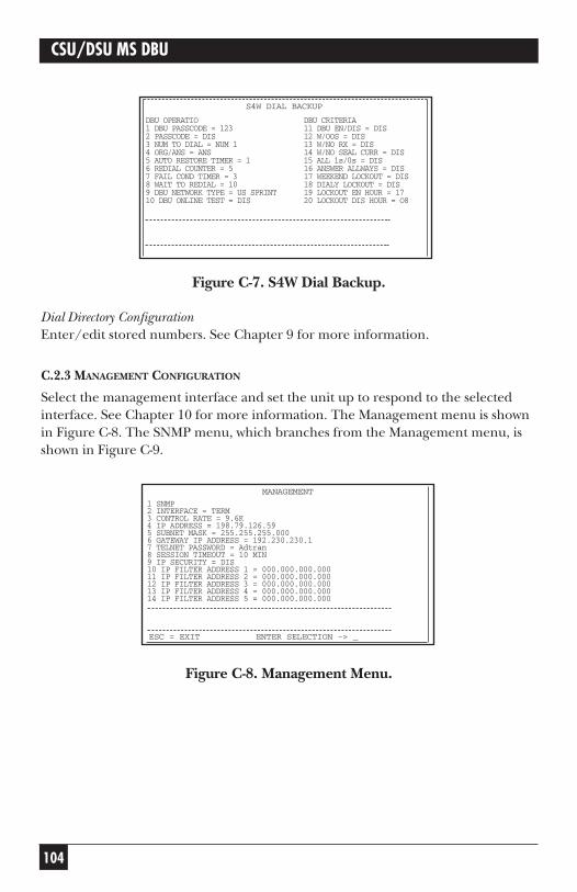
Figure C-7. S4W Dial Backup.
Dial Directory ConfigurationEnter/edit stored numbers. See Chapter 9 for more information.
C.2.3 MANAGEMENT CONFIGURATION
Select the management interface and set the unit up to respond to the selectedinterface. See Chapter 10 for more information. The Management menu is shownin Figure C-8. The SNMP menu, which branches from the Management menu, isshown in Figure C-9.
Figure C-8. Management Menu.
DBU OPERATIO DBU CRITERIA1 DBU PASSCODE = 123 11 DBU EN/DIS = DIS2 PASSCODE = DIS 12 W/OOS = DIS3 NUM TO DIAL = NUM 1 13 W/NO RX = DIS4 ORG/ANS = ANS 14 W/NO SEAL CURR = DIS5 AUTO RESTORE TIMER = 1 15 ALL 1s/0s = DIS6 REDIAL COUNTER = 5 16 ANSWER ALLWAYS = DIS7 FAIL COND TIMER = 3 17 WEEKEND LOCKOUT = DIS8 WAIT TO REDIAL = 10 18 DIALY LOCKOUT = DIS9 DBU NETWORK TYPE = US SPRINT 19 LOCKOUT EN HOUR = 1710 DBU ONLINE TEST = DIS 20 LOCKOUT DIS HOUR = O8
S4W DIAL BACKUP
104
CSU/DSU MS DBU
1 SNMP2 INTERFACE = TERM3 CONTROL RATE = 9.6K4 IP ADDRESS = 198.79.126.595 SUBNET MASK = 255.255.255.0006 GATEWAY IP ADDRESS = 192.230.230.17 TELNET PASSWORD = Adtran8 SESSION TIMEOUT = 10 MIN9 IP SECURITY = DIS10 IP FILTER ADDRESS 1 = 000.000.000.00011 IP FILTER ADDRESS 2 = 000.000.000.00012 IP FILTER ADDRESS 3 = 000.000.000.00013 IP FILTER ADDRESS 4 = 000.000.000.00014 IP FILTER ADDRESS 5 = 000.000.000.000
MANAGEMENT
ESC = EXIT ENTER SELECTION -> _

105
aAPPENDIX C: Terminal Menu StructureCHAPTER
Figure C-9. SNMP Management Menu.
C.2.4 UTILITY CONFIGURATION
View/set the time of day and date, view the LAN MAC address (if the SNMPEthernet Module is installed), enable/disable the front panel, or enter manualcommands. Chapter 11 provides more detailed information. See Figure C-10.
Figure C-10. Utility Menu.
1 SYSTEM NAME = NAME2 SYSTEM LOCATION = LOCATION3 SYSTEM CONTACT = CONTACT4 SNMP BET COMMUNITY = PUBLIC5 SNMP SET COMMUNITY = PRIVATE6 SNMP TRAP COMMUNITY = DSUIV7 SNMP TRAPS = GENERIC ONLY8 AUTHENTICAITON TRAPS = DIS9 TRAP HOST IP ADDR 1 = 000.000.000.00010 TRAP HOST IP ADDR 2 = 000.000.000.00011 TRAP HOST IP ADDR 3 = 000.000.000.00012 TRAP HOST IP ADDR 4 = 000.000.000.00013 TRAP HOST IP ADDR 5 = 000.000.000.000
SNMP
ESC = EXIT ENTER SELECTION -> _
1 TIME (HR: MN: SC) = 12:35:002 DATE (MN-DV-VR) = 03-21-993 SERIAL NUMBER = 1234567894 LAN MAC ADDRESS = 0000000000005 FRONT PANEL = EN6 ENTER MANUAL CMD
UTILITY
ESC = EXIT ENTER SELECTION -> _
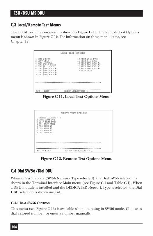
106
CSU/DSU MS DBU
C.3 Local/Remote Test MenusThe Local Test Options menu is shown in Figure C-11. The Remote Test Optionsmenu is shown in Figure C-12. For information on these menu items, seeChapter 12.
Figure C-11. Local Test Options Menu.
Figure C-12. Remote Test Options Menu.
C.4 Dial SW56/Dial DBUWhen in SW56 mode (SW56 Network Type selected), the Dial SW56 selection isshown in the Terminal Interface Main menu (see Figure C-1 and Table C-1). Whena DBU module is installed and the DEDICATED Network Type is selected, the DialDBU selection is shown instead.
C.4.1 DIAL SW56 OPTIONS
This menu (see Figure C-13) is available when operating in SW56 mode. Choose todial a stored number or enter a number manually.
1 DTE & LOOP 10 XMIT 2047 PTAN2 LOOP ONLY 11 XMIT 511 PTRN3 DTE LOOPBACK 12 XMIT DDS PTRN #14 DTE (2047 PTAN) 13 XMIT DDS PTRN #25 DTE (511 PTRN) 14 XMIT DDS PTRN #36 DTE (DDS PTRN #1) 15 XMIT DDS PTRN #47 DTE (DDS PTRN #2) 16 SELF TEST8 DTE (DDS PTRN #3)9 DTE (DDS PTRN #4)
LOCAL TEST OPTIONS
ESC = EXIT ENTER SELECTION -> _
1 REMOTE ADDRESS = 02 DATA FROM DTE3 2047 TEST PTRN4 511 TEST PTRN5 DDS PTRN #16 DDS PTRN #27 DDS PTRN #38 DDS PTRN #4
REMOTE TEST OPTIONS
ESC = EXIT ENTER SELECTION -> _

107
APPENDIX C: Terminal Menu Structure
Figure C-13. SW56 Dialing Menu.
C.4.2 DIAL DBU
This menu is available when a module is installed in the CSU/DSU MS DBU andthe Network Type is set to DEDICATED. See Chapter 13 for more information onindividual menu selections.
Figure C-14. Dial DBU Menu.
1 DIAL STORED NUMBER2 MANUAL DIAL ENTRY
DIALING MENU
ESC = EXIT ENTER SELECTION -> _
DBU OPERATIONS1 GO TO DIAL BACKUP2 DBU ONLINE TEST
DBU CONTROL MENU
ESC = EXIT ENTER SELECTION -> _
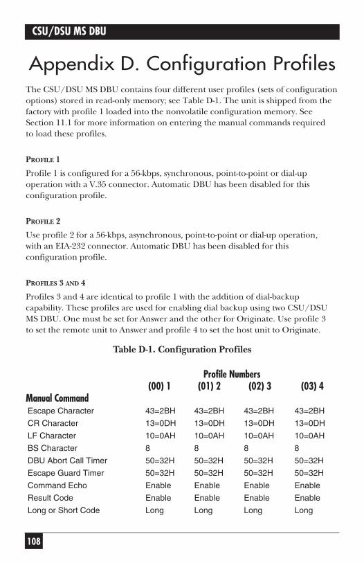
108
CSU/DSU MS DBU
Appendix D. Configuration ProfilesThe CSU/DSU MS DBU contains four different user profiles (sets of configurationoptions) stored in read-only memory; see Table D-1. The unit is shipped from thefactory with profile 1 loaded into the nonvolatile configuration memory. SeeSection 11.1 for more information on entering the manual commands requiredto load these profiles.
PROFILE 1
Profile 1 is configured for a 56-kbps, synchronous, point-to-point or dial-upoperation with a V.35 connector. Automatic DBU has been disabled for thisconfiguration profile.
PROFILE 2
Use profile 2 for a 56-kbps, asynchronous, point-to-point or dial-up operation,with an EIA-232 connector. Automatic DBU has been disabled for thisconfiguration profile.
PROFILES 3 AND 4
Profiles 3 and 4 are identical to profile 1 with the addition of dial-backupcapability. These profiles are used for enabling dial backup using two CSU/DSUMS DBU. One must be set for Answer and the other for Originate. Use profile 3to set the remote unit to Answer and profile 4 to set the host unit to Originate.
Table D-1. Configuration Profiles
Profile Numbers(00) 1 (01) 2 (02) 3 (03) 4
Manual CommandEscape Character 43=2BH 43=2BH 43=2BH 43=2BH
CR Character 13=0DH 13=0DH 13=0DH 13=0DH
LF Character 10=0AH 10=0AH 10=0AH 10=0AH
BS Character 8 8 8 8
DBU Abort Call Timer 50=32H 50=32H 50=32H 50=32H
Escape Guard Timer 50=32H 50=32H 50=32H 50=32H
Command Echo Enable Enable Enable Enable
Result Code Enable Enable Enable Enable
Long or Short Code Long Long Long Long
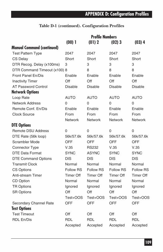
109
APPENDIX D: Configuration Profiles
Table D-1 (continued). Configuration Profiles
Profile Numbers(00) 1 (01) 2 (02) 3 (03) 4
Manual Command (continued)Test Pattern Type 2047 2047 2047 2047
CS Delay Short Short Short Short
DTR Recog. Delay (x100ms) 3 3 3 3
DTR Command Timeout (x100) 8 8 8 8
Front Panel En/Dis Enable Enable Enable Enable
Inactivity Timer Off Off Off Off
AT Password Control Disable Disable Disable Disable
Network OptionsLoop Rate AUTO AUTO AUTO AUTO
Network Address 0 0 0 0
Remote Conf. En/Dis Enable Enable Enable Enable
Clock Source From From From From
Network Network Network Network
DTE OptionsRemote DSU Address 0 0 0 0
DTE Rate (56k loop) 56k/57.6k 56k/57.6k 56k/57.6k 56k/57.6k
Scrambler Mode OFF OFF OFF OFF
Connector Type V.35 RS232 V.35 V.35
DTE Data Format SYNC ASYNC SYNC SYNC
DTE Command Options DIS DIS DIS DIS
Transmit Clock Normal Normal Normal Normal
CS Options Follow RS Follow RS Follow RS Follow RS
Anti-stream Timer Timer Off Timer Off Timer Off Timer Off
CD Option Normal Normal Normal Normal
TR Options Ignored Ignored Ignored Ignored
SR Options Off Off Off Off
Test+OOS Test+OOS Test+OOS Test+OOS
Secondary Channel Rate OFF OFF OFF OFF
Test OptionsTest Timeout Off Off Off Off
RDL En/Dis RDL RDL RDL RDL
Accepted Accepted Accepted Accepted

110
CSU/DSU MS DBU
Table D-1 (continued). Configuration Profiles
Profile Numbers(00) 1 (01) 2 (02) 3 (03) 4
Test Options (continued)EIA Controlled LLB Disable Disable Disable Disable
EIA Controlled RLB Disable Disable Disable Disable
DBU Answer Test Disable Disable Disable Disable
Dial OptionsAutomatic DBU Disable Disable Enable Enable
DBU Number to Dial #1 #1 #1 #1
DBU Originate/Answer Answer Answer Answer Originate
DBU when OOS Enable Enable Enable Enable
DBU when No RX Signal Enable Enable Enable Enable
DBU when No Sealing Current Enable Enable Enable Enable
DBU Auto Restore Timer 1 minute 1 minute 1 minute 1 minute
DBU Redial Counter 5 5 5 5
DBU Fail-Timer (x10 seconds) 3 3 3 3
DBU Redial Wait Time 10 10 10 10
When all 1s/0s Disable Disable Disable Disable
Network Type AT&T AT&T AT&T AT&T
Error Control Auto Auto Auto Auto
V.42/MNP V.42/MNP V.42/MNP V.42/MNP
Flow Control (V.32) CTS Only CTS Only CTS Only CTS Only
Data Compression (V.32) Enabled Enabled Enabled Enabled

111
APPENDIX E: DSU-to-Modem Interconnect
Appendix E. DSU-to-ModemInterconnect
Modem Tail-Circuit ApplicationA DSU-to-modem interconnect diagram for a modem tail-circuit application isshown in Figure E-1.
Figure E-1. DSU to Modem Interconnect.
MODEM
DSU
IV
RC
ETC
RD
TD
DCD
RTS
ETC
RC
TD
RD
RTS
DCD
For Multi-drop requirement:
MODEM
CSU /DSU
MS
DBU

112
CSU/DSU MS DBU
Appendix F. Specifications
Operating Modes• Dedicated DDS (point-to-point, multipoint)
• Switched 56 (4-wire)
• ISDN (1B+D)
• PSTN (V.34)
Network Data Rates• Dedicated-mode service rates: 2.4, 4.8, 9.6, 19.2, 38.4, 56, and 64 kbps
• Switched-mode service rate: 56 kbps
• Dial Backup: Switched 56 (56 kbps), V.34 (2.4 to 33.6 kbps), ISDN (56 or64 kbps)
DTE Rates Provided• DTE rates match service rates
• DTE-to-loop rate matching in both dedicated and switched modes
• Synchronous rates: 2.4, 4.8, 9.6, 19.2, 38.4, 56, and 64 kbps
• Asynchronous rates: 2.4, 4.8, 9.6, 19.2, 38.4, and 57.6 kbps
DTE InterfacesBoth EIA-232 and V.35 electrical and physical DTE interfaces

113
APPENDIX F: Specifications
SNMP and TELNET• Integrated SLIP/PPP port
• Physical connector RJ-48 female and DB25
• Optional 10BASE-T interface with SNMP Ethernet Module
• MIB II RFC 1213 complaint
• Enterprise-specific MIB
• SNMP traps
Clocking• Normal DDS (slaved to network receive clock)
• Private network master (internal)
• Normal DDS tail circuit
• Private network master (slaved to external clock)
Switched Mode Dialing Options• Stored number
• Front-panel keypad
• DTR dialing of stored numbers
• In-band AT commands
• V.25 bis in-band dialing
Diagnostics• Network: CSU and DSU loopbacks
• User: Local DTE and loop, remote V.54
• Test Patterns: 2047, 511, DDS stress patterns 1-4
114
CSU/DSU MS DBU
Line RequirementsLoop transmission parameters as defined in:
AT&T PUB 62310: Dedicated DDSAT&T PUB 4146B: Switched 56Sprint TS 0046: Switched 56
Line InterfaceRJ-48 female, 4-wire, full duplex
Receiver Sensitivity-45 dB at all rates
Agency ApprovalsUL® 1950C-U.L. 1950FCC Part 15, Class AFCC Part 68CS03
EnvironmentOperating Temperature: 32 to 122°F (0 to 50°C)
Storage Temperature: -4 to +158°F (-20 to +70°C)
Relative Humidity: Up to 95%, noncondensing
Hardware SpecificationsDimensions: 2.4"H x 8"W 10.4"D (6.1 x 20.3 x 26.4 cm)
Weight: 4.5 lb. (2 kg)
Power: 115 VAC, 75 mA max., 8.6 watts

1000 Park Drive • Lawrence, PA 15055-1018 • 724-746-5500 • Fax 724-746-0746
© Copyright 1998. Black Box Corporation. All rights reserved.