Embed Size (px)
Citation preview

CSR Fibre CementWet Area Systems.
FC101 September 2002

CSR Fibre CementWet Area Systems.2.
Advantages.• Simple and quick to install.
• Low installed cost.
• Immune to permanent water damage.
• Covered by the CSR Internal Lining Guarantee.
• Smooth sanded surface ready for finishing.
• Maintenance free.
• A suitable substrate for all forms of decorativefinishing.
Applications.Australian Standard AS3740 : 1994 ‘Waterproofing
of wet areas within residential buildings’ defines wetareas in two categories.
Category 1 wet areas; are those wall and floor areasenclosing a shower compartment, i.e. part wall areas ofshowers within bathrooms and ensuites.
Category 2 wet areas; are those part walls adjacentto fixed vessels such as baths, toilets and tubs, i.e. partwall areas within bathrooms, ensuites, laundries andkitchens other than the wall area enclosing a shower.
The CSR Fibre Cement Wet Area Lining Systemsoffer proven, reliable and cost effective solutions toboth categories.
CATEGORY 1.SHOWER RECESS AREAS.
CSR Fibre Cement Wallboard is used inCategory 1 areas as a substrate for ceramic tiles, andmust be fastened with nails or screws only.
Wallboard sheets are then jointed with CSRGyprock®/Fibre Cement Wet Area Base Coat and tape.
CATEGORY 2. GENERAL WET AREAS.
CSR Fibre Cement Wallboard is installed into theseareas in a similar manner to that used for fixingstandard Gyprock® plasterboard.
Wallboard sheets to be used as a substrate for tilingmust be fixed with nails or screws only.
Contents.WET AREA LINING SYSTEMS.
Description, Advantages, Applications. 2.Material Properties. 3.Components. 3.Sheet Preparation. 4.Handling, Storage & Safety. 5.Control Joints. 5.Framing. 6.Wallboard Installation. 6 – 7.General Wet Area Flashing. 8.Shower Recess Construction. 9 – 11.Bath, Shower Over Bath and Unenclosed Shower Construction. 12 – 13.Caulking & Flashing Details. 14.Jointing Systems & Decoration. 15 – 19.
WET AREA FLOORING SYSTEM.Description & Advantages. 20.Material Properties. 20.Components. 20.Framing. 21.Sheet Preparation. 21.Installation. 21.Waterproofing. 22 – 23.Tile Laying. 23.Health & Safety. 24.
Wet AreaLining Systems.
DESCRIPTION.CSR Fibre Cement Wallboard is an autoclaved,
cellulose fibre reinforced cement sheet which isimmune to permanent water damage and will not rot.
It is specifically designed for use in the lining ofwalls in kitchens, bathrooms, laundries, toilets andother areas commonly known as ‘wet areas’ indomestic buildings.
CSR Fibre Cement Wallboard has a recess on bothlong edges so that sheets may be taped and set with CSRGyprock®/Fibre Cement jointing materials. Oncejointed, it may be tiled, painted or wallpapered as desired.
An appraisal by the Building Research Associationof New Zealand (BRANZ Appraisal CertificateNº97/007), confirms the suitability of the CSR FibreCement Wet Area Lining Systems (excluding theCompressed Sheet Wet Area Flooring System) detailedin this technical literature.

CSR Fibre CementWet Area Systems.3.
Width mm.Length mm.
1800
2400
2700
3000
3600
4200
900
✓
✓
✓
1200
✓
✓ ■ ✤
✓ ■ ✤
✓ ■ ✤
✓
✓
1350
✓
✓
✓
Thickness(6mm RE = ✓) (9mm RE = ■) (12mm RE = ✤)
FASTENERS.To guarantee performance, only approved fasteners
should be used in these systems.
CSR Fibre Cement Wallboard Nails: Hot-dipgalvanised for softwood and hardwood framing.
• For 6mm sheet – 2.8mm x 30mm.• For 9mm sheet – 2.8mm x 40mm.• For 12mm sheet – 2.8mm x 40mm.
Components.CSR FIBRE CEMENT WALLBOARD.CSR Fibre Cement Wallboard is manufactured in
the following sizes, with the two long edges recessedto allow seamless jointing.
STUD ADHESIVE (FOR NON TILED AREAS ONLY).
• Gyprock® Acrylic Stud Adhesive.
JOINTING MATERIALS.• CSR Gyprock®/Fibre Cement Wet Area Base Coat.
• Gyprock® Paper Joint Reinforcing Tape.
• Gyprock Easytape™.
• Gyprock® finishing compounds (non tiled areas only).
VERTICAL CORNER FLASHING.• External Vertical Flashing Angle: CSR Fibre
Cement PVC angle 50 x 50mm. For use withexternal and preformed shower trays.
• Internal Vertical Flashing: A liquid appliedmembrane such as ABA Superflex™ I, with a bondbreaker (supplied by others). For use with internalshower trays.
PERIMETER FLASHING.
• Perimeter Flashing Angle: CSR Fibre CementPVC angle 75 x 50mm.
• Perimeter Flashing for Step-Down Slab: Suchas Hypalon™ Flashing Strip 130mm width (suppliedby others).
• Proprietary Insitu Membranes: Such as ABASuperflex™ I with bond breaker.
FLEXIBLE SEALANT.• Dow Corning Brick & Concrete Crack Sealant.
• Selleys™ Brick & Concrete Sealant.
NOTE: Only use sealants suitable for cement andconcrete substrates.
FIRE RESISTANCE.Under the Building Code of Australia, C1.1 Clause
2.5(e), CSR Fibre Cement is deemed to be non-combustible.
The Fire Hazard Properties, when tested inaccordance with AS1530.3 are as follows:
FIRE HAZARD INDICES.
Ignitability 0
Spread of Flame 0
Heat Evolved 0
Smoke Developed 0
MaterialProperties.
CSR Fibre Cement Compressed Sheet conforms tothe requirements of AS2908.2 : 1992 ‘Cellulose-cement products Part 2: Flat sheets’.
MANUFACTURING TOLERANCES.
Mass 6mm thickness (nominal) 9kg/m2
Mass 9mm thickness (nominal) 13.5kg/m2
Mass 12mm thickness (nominal) 18.3kg/m2
Length +0 to -4mm
Width +0 to -3mm
Thickness +0.5 to -0mm
Diagonals Difference (max) 3mm
Screws for fixing CSR Fibre Cement Wallboardto Steel Framing
• Buildex FibreTEKS™, Class 3 finish, 9-18 x 30mm.
• Buildex FibreTEKS™, Class 3 finish, 9-18 x 20mm.

CSR Fibre CementWet Area Systems.4.
Score along straight edgethen lift sheet upwards to form clean break
Hand Guillotine.
Hand Saw.
Preferably use an old handsaw. A quick jabbingaction is best. Work with sheet face up to preventburrs forming on the face.
SheetPreparation.
CUTTING.CSR Fibre Cement Sheets may be cut on-site using
any of the following methods.
Tungsten Tipped Score and Snap Knife.
1. Score face of sheet 4 to 5 times using a tungstentipped knife against a straight edge.
2. Support the scored edge with the straight edge andsnap the sheet upwards for a clean break.
ON-SITE RECESSING.
Where it is necessary to produce a ground recess,on-site, a dustless angle grinder should be used. CSRrecommends using the Hitachi Easy Bevel withvacuum extraction system, which fits most 125mmgrinders, and produces a superior finish.
The recess should not exceed 1.5mm at its deepestpoint, and should be approximately 35mm wide.
Where edges have been site recessed, ensure therecesses are primed prior to the application of thetexture coating. Always follow the texture coatingmanufacturer’s recommendations.
Power Saw.
When it is necessary to use power tools for cuttingCSR Fibre Cement Sheets, CSR recommends usingthe Hitachi Fibre Cement Power Saw Blade. Thisblade is specifically designed for use with fibre cementand produces a superior cut compared to conventionalblades.
It is ideal for use with the Hitachi C7YA dustlesscircular saw and other 185mm circular saws fitted withvacuum extraction systems.
Hitachi C7YA DustlessCircular Saw with DustExtraction System.
Hitachi Fibre CementPower Saw Blade.
Hitachi Easy Bevel Attachmentwith Dust Extraction Systemfitted to a grinder.
CSR Fibre CementWet Area Systems.5.
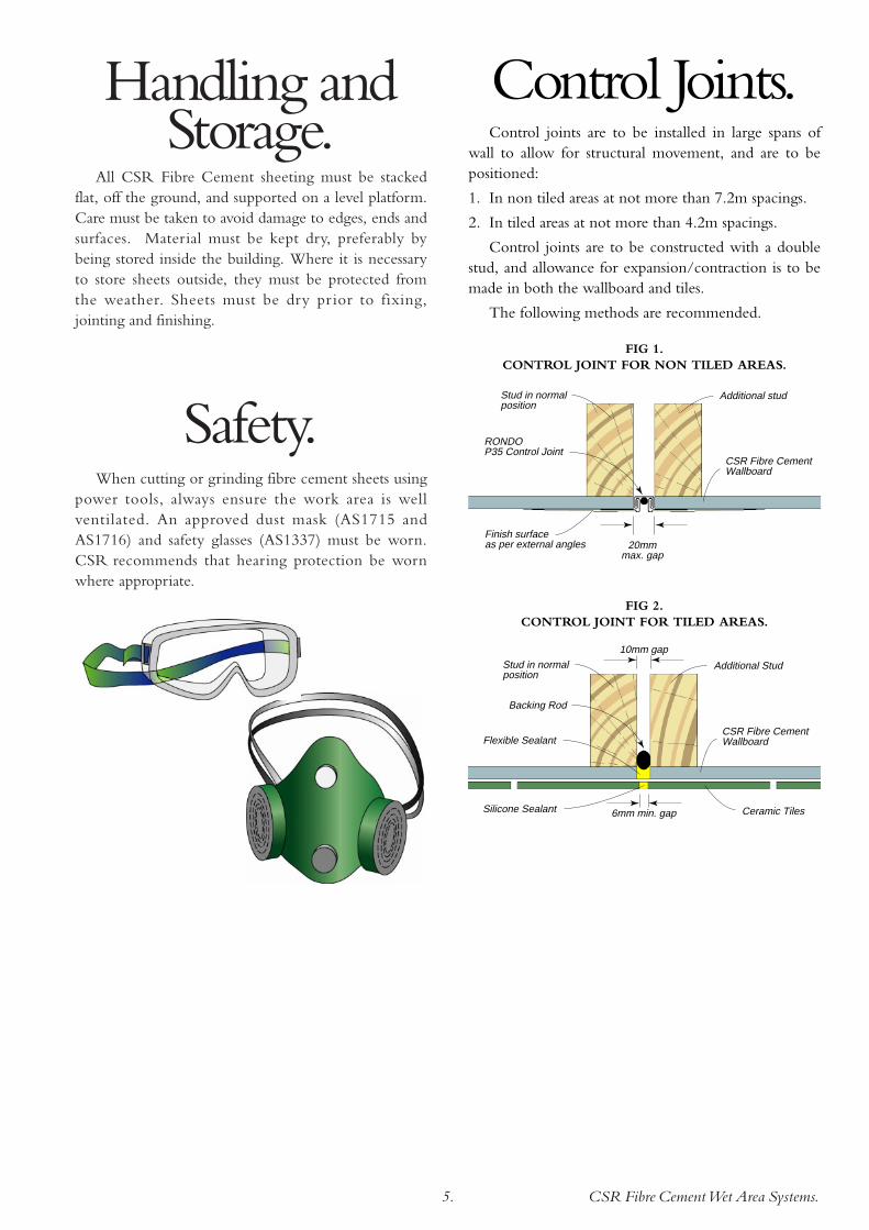
Handling andStorage.
All CSR Fibre Cement sheeting must be stackedflat, off the ground, and supported on a level platform.Care must be taken to avoid damage to edges, ends andsurfaces. Material must be kept dry, preferably bybeing stored inside the building. Where it is necessaryto store sheets outside, they must be protected fromthe weather. Sheets must be dry pr ior to fixing,jointing and finishing.
Safety.When cutting or grinding fibre cement sheets using
power tools, always ensure the work area is wellventilated. An approved dust mask (AS1715 andAS1716) and safety glasses (AS1337) must be worn.CSR recommends that hearing protection be wornwhere appropriate.
Control Joints.Control joints are to be installed in large spans of
wall to allow for structural movement, and are to bepositioned:
1. In non tiled areas at not more than 7.2m spacings.
2. In tiled areas at not more than 4.2m spacings.
Control joints are to be constructed with a doublestud, and allowance for expansion/contraction is to bemade in both the wallboard and tiles.
The following methods are recommended.
CSR Fibre CementWallboard
20mmmax. gap
RONDOP35 Control Joint
Stud in normal position
Additional stud
Finish surface as per external angles
CSR Fibre CementWallboard
6mm min. gap
10mm gap
Backing Rod
Stud in normal position
Additional Stud
Ceramic Tiles
Flexible Sealant
Silicone Sealant
FIG 1. CONTROL JOINT FOR NON TILED AREAS.
FIG 2. CONTROL JOINT FOR TILED AREAS.

CSR Fibre CementWet Area Systems.6.
200mm max.
300mm max.
6mm gap 12mm min.
12mm min.
Fix 50mm min. from edge of sheet at corners
600mm max. Stud Centres
Butt Joint
Noggings at 1350mm max. vertical centres
WallboardInstallation.
Generally, it is recommended that all Wallboardsheets be applied horizontally. This is to reduce theextent of joint visibility in glancing light conditions.Sheets may be fixed vertically in tiled areas or wherejoint visibility is not an issue.
Butt joints must be staggered a minimum of600mm in adjacent sheets.
Avoid butt joints over doorways and windows. Wherethese are unavoidable, they are to be positioned aminimum 200mm from jamb studs, and formed on a stud.
Install the bottom sheet first, with the lower edge aminimum 6mm clear of the finished floor.
Fasteners are to be positioned a minimum of 12mmfrom the edge of the sheet and a minimum 50mmfrom sheet corners. Fasteners are to be left a maximumof 0.5mm below the sheet surface.
NON TILED AREAS.For non tiled areas, position fasteners at 300mm
maximum centres in the body of the sheet, and at200mm centres at internal angles, external angles andbutt joints.
FIG 4. WALLBOARD INSTALLATION. FASTENER METHOD NON TILED AREAS.
Framing.CSR Fibre Cement Wallboard may be fixed to
either timber or steel framing.
Timber framing must comply with AS1684 : 1992‘National Timber Framing Code’.
Steel framing must comply with AS3623 : 1993‘Domestic Metal Framing’.
Studs shall be plumb and true, and spaced atmaximum 600mm centres. Noggings are to be placedbetween all studs at 1350mm maximum verticalcentres.
When an external shower tray or perimeter angleflashing is used, it is not permitted to fix the wallboardsheet to the bottom plate. An additional row ofnoggings must be placed 25mm above the tray orflashing to allow the wallboard to be fastened.
Similarly, noggings are to be placed 25mm above apreformed shower base, sink or bath tub. Also providesuitable noggings to support the bath and other fixturessuch as soap holders and towel rails.
Wall framing may be checked-out to a maximumdepth of 20mm to accommodate the bath or showerbase flange. Alternatively, provide furring to ensure theface of the CSR Fibre Cement Wallboard will finish infront of the upturn on the receptacle.
CSR Fibre CementWallboard
Thermal break materialto BRANZ recommendations
Steel Stud
FIG 3. THERMAL BRIDGING ON STEEL FRAMING.
EXTREME CLIMATIC CONDITIONS.When CSR Fibre Cement Wallboard is fixed to
steel framing in extreme climates, insulating materialsare required between the wallboard and the frame toisolate components subject to thermal movement.

CSR Fibre CementWet Area Systems.7.
TILED AREAS.Position fasteners at 200mm centres maximum at
sheet edges and ends, internal and external angles aswell as in the body of the sheet.
CSR Fibre Cement Wallboard, to be used as asubstrate for tiling, must be fixed to the framing withnails or screws.
Use of stud adhesive is NOT acceptable.
These fixing details are suitable for wall tiles up to20kg/m2 in weight. For wall tiles up to 32kg/m2,sheets must be fixed at 100mm maximum centres to allstuds.
6mm gap12mm min.
12mm min.
Fix 50mm min. from edge of sheet at corners
600mm max. Stud Centres
Butt Joint
Noggings at 1350mm max. vertical centres
200mm max.
200mm max.
200mm max.
FIG 6. WALLBOARD INSTALLATION.FASTENER METHOD
TILED AREAS.
200mm max. 230mm
max.
6mm gap12mm min.
12mm min.
Fix 50mm min. from edge of sheet at corners
600mm max. Stud Centres
AdhesiveWalnuts
Fix temporary block at sheetcentre untiladhesive sets
Butt Joint
Noggings at 1350mm max. vertical centres
FIG 5. WALLBOARD INSTALLATION. ADHESIVE/FASTENER METHOD
NON TILED AREAS.
Alternatively the adhesive/fastener system may beused.
Apply 25mm x 15mm ‘walnuts’ of CSR Gyprock®
Stud Adhesive at 230mm maximum centres tointermediate studs.
Hold sheet against studs for 24 hours by fastenersdriven through temporary fibre cement blocks in thecentre of sheet at every second stud. Fasteners are to beapplied at sheet edges as shown in the diagram.
Note: ‘Walnuts’ of adhesive must NEVER coincidewith fastening points.
CSR Fibre CementWet Area Systems.8.
CSR Fibre CementWallboard
Ceramic Tiles
Approved Flashing
Ceramic Tiles
Flexible Sealant
Mortar bed
25mmmin.
Stepped concreteslab or hob cast integrally with slab
6mm
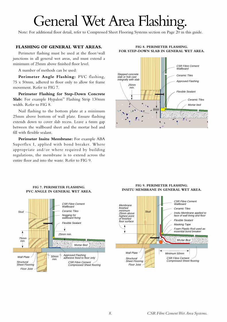
FIG 8. PERIMETER FLASHING.FOR STEP-DOWN SLAB IN GENERAL WET AREA.
CSR Fibre CementWallboard
Ceramic Tiles
Wall Plate
Structural Sheet Flooring
Stud
Flexible Sealant
Nogging for wallboard fixing
Floor Joist
Approved Flashing adhesive fixed to floor only50mm
min.
75mmmin.
25mm min.
CSR Fibre Cement Compressed Sheet flooring
Mortar Bed
FIG 7. PERIMETER FLASHING.PVC ANGLE IN GENERAL WET AREA.
FIG 9. PERIMETER FLASHING. INSITU MEMBRANE IN GENERAL WET AREA.
CSR Fibre CementWallboard
Ceramic Tiles
Wall Plate
Structural Sheet Flooring
Masking Tape
Flexible Sealant
Stud
Floor Joist
Membranefinishedminimum25mm above highest point of finishedfloor surface
Minimum 50mm
Foam Plastic Rod used as essential bond breaker
Insitu Membrane applied to face of wall lining and floor
CSR Fibre Cement Compressed Sheet flooring
FLASHING OF GENERAL WET AREAS.Perimeter flashing must be used at the floor/wall
junctions in all general wet areas, and must extend aminimum of 25mm above finished floor level.
A number of methods can be used:
Per imeter Angle Flashing: PVC flashing,75 x 50mm, adhered to floor only to allow for framemovement. Refer to FIG 7.
Perimeter Flashing for Step-Down ConcreteSlab: For example Hypalon™ Flashing Strip 130mmwidth. Refer to FIG 8.
Nail flashing to the bottom plate at a minimum25mm above bottom of wall plate. Ensure flashingextends down to cover slab recess. Leave a 6mm gapbetween the wallboard sheet and the mortar bed andfill with flexible sealant.
Perimeter Insitu Membrane: For example ABASuperflex I, applied with bond breaker. Whereappropr iate and/or where required by buildingregulations, the membrane is to extend across theentire floor and into the waste. Refer to FIG 9.
General Wet Area Flashing.Note: For additional floor detail, refer to Compressed Sheet Flooring Systems section on Page 20 in this guide.

CSR Fibre CementWet Area Systems.9.
FIG 10. TYPICAL DETAIL FORPREFORMED SHOWER BASE.
FIG 12. PREFORMED SHOWER BASEON CONCRETE FLOOR.
Preformed Shower Base
Noggings 25mm above shower base for wallboard fixing
PVC Flashing Angle PVC Flashing
Angle
PVC Flashing Angle
Fix at 600mm vertical centres
Jointing system A or B (refer to page 15)
PVCAngle and Sealant to 1800mm min. above finished shower floor (refer to FIG 26)
CSR Fibre CementWallboard
Ceramic Tiles
Mortar Bed
6mm
Steel TrackNogging
Flexible Sealant
Steel orTimber Stud
PreformedShower Base
SteelWall Plate
Perimiter Flashing (optional as per AS3740)
NOTE: Australian Standard AS3740 states that –The height of the sides of a shower tray above thehighest point of the finished floor surface shall be thegreater of –
i) 75mm; or
ii)25mm above the maximum possible water levelin the shower compartment.
Shower RecessConstruction.
PREFORMED SHOWER BASE.
A preformed shower base has the advantage of
being easy to install over floors of timber, compressed
fibre cement sheet and concrete slabs, as well as
ensuring that the wall linings are kept clear of any free
water likely to accumulate on the shower floor.
A preformed shower base must be installed before
the wall linings.
Cut and install PVC angle to internal corner, fixing
the angle to studs at 600mm centres. Carry angle
down over the shower base lip, stopping 6mm above
shower base. PVC angle is to extend a minimum
height of 1800mm from the finished floor surface.
Cut and fix the CSR Fibre Cement Wallboard,
leaving a 6mm gap between the bottom edge of the
sheet and the shower base, between the sheet and the
floor, and between sheets forming internal corner.
Neatly cut holes for plumbing penetrations.
Caulk around plumbing penetrations, the gap
between the CSR Fibre Cement Wallboard and the
shower base, and up internal corner of shower with
flexible sealant.
Perimiter Flashing (optional as per AS3740)
Mortar Bed
6mm
PreformedShower Base
Nogging
StudCSR Fibre CementWallboard
Ceramic Tiles
Flexible Sealant
Wall Plate
Floor Joist
CSR Fibre Cement Compressed Sheet flooring
FIG 11. PREFORMED SHOWER BASEON SHEET FLOORING.

CSR Fibre CementWet Area Systems.10.
EXTERNAL SHOWER TRAY.Install the shower tray, as per the
regulations, prior to the installation ofCSR Fibre Cement Wallboard.
Cut and install PVC angle tointernal corner, fixing the angle tostuds at 600mm centres. Carry angledown inside the shower tray, stoppingas detailed in FIG 13 or 26. PVCangle is to extend a minimum heightof 1800mm from the finished floorsurface.
Cut and fix the CSR Fibre CementWallboard, leaving a 6mm gapbetween the sheet and the floor, andbetween sheets forming the internalcorner.
Neatly cut holes for plumbingpenetrations.
Caulk around plumbingpenetrations, the gap between theCSR Fibre Cement Wallboard and theshower tray (or mortar bed), and upthe internal corner of shower recesswith flexible sealant.
Fill gap at base of Wallboard with Flexible Sealant
CSR Fibre CementWallboard
Ceramic Tiles
Ceramic Tiles6mm
Flexible Sealant
25mm
Shower Tray adhesive fixed to floor only
Additional Nogging for fixing of wallboard. (Do not fix wallboard through shower tray into wall plate)
CSR Fibre Cement Compressed Sheet flooring
Mortar bed
Stud
75mm min. above highest point of shower floor and min. 25mm above max. possible water level
FIG 14. EXTERNAL TRAY SHOWER RECESS FORSHEET FLOORING.
CSR Fibre CementWallboard
Timber or steel stud
Ceramic Tiles
Ceramic Tiles or otherimpervious finish
Mortar bed
6mm
min
.
100m
m m
in.
75m
m m
in.
Masking tape as bond breaker behind sealant
Fill gap between Wallboard and mortar bed with Flexible Sealant
External Shower Tray
Nogging to allow fixing of Wallboard above tray level
Flexible Sealant
6mm
typi
cal
FIG 15. EXTERNAL TRAY SHOWER RECESS FORSET-DOWN CONCRETE SLAB.
Perimeter Flashing (refer to FIG 7 or 9)
Seal flashing angle to tray
Shower Tray
Additional Noggings for Wallboard fixing as per system requirement
PVC Flashing Angle and Sealant to 1800mm min. above finished shower floor (refer to FIG 26)
Jointing system A or B (refer to page 15)
Seal between tray and wallboard
FIG 13. TYPICAL DETAIL FOREXTERNAL SHOWER TRAY.

CSR Fibre CementWet Area Systems.11.
15mm min. to finished shower floor level
Timber or Steel stud
CSR Fibre CementWallboard
Ceramic Tiles
Masking Tape
Flexible Sealant
Foam Plastic Rodused as essentialbond breaker
Insitu Internal Trayapplied to face of wall lining and floor
50mmmin.
Mortar Bed
75mm min. above highest point of shower floor and min. 25mm above max. possible water level
Perimeter flashing (optional as per AS3740)
FIG 18. INSITU INTERNAL TRAY SHOWER RECESS(CERAMIC TILED) FOR SET-DOWN SLAB.
Flexible Sealant
Foam Plastic Rodused as essentialbond breaker
CSR Fibre CementWallboard
Ceramic Tiles
Masking Tape
Insitu Internal Trayapplied to face of wall lining and floor
Additional Noggingfor wallboard fixingwhen external angle flashing is installed
Wall Plate
Structural Sheet Flooring
Stud
Floor Joist
75mmmin.
25mm
150mmmin.
Perimeter flashing (optional as per AS3740)
50mmmin.
CSR Fibre Cement Compressed Sheet flooring
Mortar Bed
INSITU-FORMED INTERNALSHOWER TRAY.
Install flashing angle to wall/floorjunction. Cut and fix the CSR FibreCement Wallboard, leaving a 6mm gapbetween the sheet and the floor, andbetween sheets forming internalcorner.
Neatly cut holes for plumbingpenetrations.
Caulk around plumbingpenetrations and up internal corner ofshower with flexible sealant.
Propr ietary liquid membranematerials are applied to the face of theCSR Fibre Cement Wallboard andfloor to form an insitu internal tray.Follow respective manufacturers’instructions.
Apply membrane to the verticalcorner to a minimum height of1800mm from the finished floorsurface. The flashing membrane is toextend 75mm minimum each side ofthe corner. Refer to FIG 16 and 27.
A compatible tile adhesive must beused to fix tiles to the membrane.
Important: Only insitumembrane mater ials appraised byrecognised authorities are to be used.For example ABA Superflex I.
FIG 17. INSITU INTERNAL TRAY SHOWER RECESS(CERAMIC TILED) FOR SHEET FLOORING.
75mmmin.
75mm
75mmmin.
75mm
150mm 150mm
Perimeter Flashing (refer to FIG 7 or 9)
Internal flashing membrane to 1800mm min. above finished shower floor
Optional continuation of perimeter flashing
Jointing system A or B (refer to page 15)
Sealant between sheets (refer to FIG 27)
Insitu Membrane
FIG 16. TYPICAL DETAIL FORINSITU INTERNAL TRAY SHOWER RECESS .

CSR Fibre CementWet Area Systems.12.
FIG 19. INSTALLATION LAYOUT FOR ASHOWER OVER BATH OR UNENCLOSED SHOWER AREA.
SHOWER OVER BATH ANDUNENCLOSED SHOWER.
Install flashing angle to wall/floor junction. Cut andfix the CSR Fibre Cement Wallboard, leaving a 6mmgap between the sheet and the floor, the sheet and thebath, and between sheets forming internal corner.
Neatly cut holes for plumbing and bathpenetrations.
Caulk around plumbing and bath penetrations andup internal corner of shower with flexible sealant.
Proprietary liquid membrane materials are appliedto the face of the CSR Fibre Cement Wallboard andthe floor. Refer to FIG 19 and 9
Always follow respective manufacturers’instructions.
For showers, apply a membrane to the verticalcorner to a minimum height of 1800mm from thefinished floor surface. The flashing membrane is toextend 75mm minimum each side of the corner. Referto FIG 19 and 27
A compatible tile adhesive must be used to fix tilesto the membrane.
Important: Only insitu membrane mater ialsappraised by recognised authorities are to be used. Forexample ABA Superflex I.
Bath, Shower Over Bath andUnenclosed Shower Installations.
1500mm min. 1500mm min.
Minimum extent of tiled area
Minimum extent of tiled area
Tiles optional on walls around bath
50mm min. on floor
Membrane to extend 1500mm min. radius from shower rose
Membrane to extend 1800mm min. from floor (refer to FIG 27)
Jointing systemA or B (refer to page 15)
Refer to FIG 23 or 28
Refer to FIG 22
Refer to FIG 22
Refer to FIG 7 or 9
Refer to FIG 7 or 9Refer to
FIG 9
1800mm
75mmmin.
75mmmin.
150mm min.
150mmmin.
150mmmin.
150mmmin.
Extent of tiles above the bath 150mm min.

CSR Fibre CementWet Area Systems.13.
FIG 20. INSTALLATION LAYOUT FOR ABATH WITHOUT SHOWER.
BATH WITHOUT SHOWER.
Extent of tiles150mm min.
Refer to FIG 24 or 25
FIG 21. TYPICAL HAND BASIN INSTALLATION DETAIL.
Tiles optional on walls around bath
Refer to FIG 23 or 28
Refer to FIG 22
50mm min. on floor
Refer to FIG 7 or 9
Refer to FIG 7 or 9
Refer to FIG 9
Membraneflashing
150mm min.
150mm min.
150mm min.
150mm min.
150mm min.
Extent of tiles above bath (150mm min.)

CSR Fibre CementWet Area Systems.14.
FIG 28. BATH INSTALLATION – STEEL STUD WALL.
Ceramic Tiles
6mm
Flexible Sealant
Steel Stud
Bath
CSR Fibre Cement Wallboard
RONDOPart Nº 255 Top Hat Section to support bath and strengthen framing OR Stiffen Stud to engineer’s detail
Fixings100mmmax.
Notch Stud20mm max.
Insitu membrane (150mm min. height)
Mortar Bed
CSR Fibre Cement Wallboard
Ceramic TilesTap Body
Batten
Stud
FlexibleSealant
To assist in cutting a neat hole for Plumbing Fixtures, the use of a Hole Saw is recommended
6mm gap
6mm gap
CSR Fibre CementWallboard
Ceramic Tiles
6mm
Nogging
Noggingto supportbath
Flexible Sealant
Stud
Bath
Notch Stud20mm max.
Insitu membrane (150mm min. height)
Nogging
Stud
Tub orBasin
CSR Fibre CementWallboard
Ceramic Tiles (to150mm min. height)
Flexible sealant
FIG 22. TAP INSTALLATION.ELEVATION.
FIG 23. BATH INSTALLATION.
FIG 24. LAUNDRY TUB/BASIN INSTALLATION.(CONTINUOUS LININGS)
FIG 25. ALTERNATIVE TUB/BASIN INSTALLATION(DISCONTINUOUS LININGS)
Ceramic Tiles (to 150mm min. height)
CSR Fibre CementWallboard
Nogging
6mm
Flexible Sealant
Tub orBasin
Stud
Insitu membrane (150mm min. height)
Ceramic Wall Tiles
CSR Fibre Cement Wallboard
Expansion Gapfilled with Flexible Wet Area Sealant
6mm Expansion Gapfilled with Flexible Wet Area Sealant
Stud Stud
Stud
Corner Blocking
WallPlate
WallPlate
WallPlate
PVC Angle Flashing to 1800mm min. above finished floor level
FIG 26. PVC ANGLE FLASHING AT SHOWER OR
SHOWER OVER BATH INTERNAL CORNER.
Ceramic tiles
Stud
Stud Stud
CSR Fibre Cement Wallboard
Expansion Gapfilled with Flexible Wet Area Sealant
6mm Expansion Gapfilled with Flexible Wet Area Sealant
Corner Blocking
WallPlate
WallPlate
WallPlate
Insitu membrane to 1800mm min. above finished floor level (75mm min. width each side of corner)
FIG 27.INSITU-MEMBRANE FLASHING AT SHOWER OR
SHOWER OVER BATH INTERNAL CORNER.

CSR Fibre CementWet Area Systems.15.
Jointing Systems.After fixing CSR Fibre Cement Wallboard, the joints, corners and
fastener heads require stopping to provide a surface suitable for decorating.
NOTE:
① It is a requirement of the BCA that a water resistant taping compound, such as CSR Gyprock®/Fibre CementWet Area Base Coat be used in these applications.
Category 1 & 2 Wet Areas:
These are defined in AS3740 ‘Waterproofing wet areas within buildings’.
Areas of High Humidity:
These are defined as either buildings in Australia north of the Tropic of Capricorn, or any application protectedfrom the weather but exposed to the outside air environment, such as carport ceilings and soffits.
Jointing Tape Coat Tape Second Coat Finish CoatSystem
Tiled Areas and Category 1 & 2 Wet Areas ①
A Wet Area Base Coat Paper Tape Wet Area Base CoatNone
B Wet Area Base Coat Easytape™ Wet Area Base Coat
Non-Tiled Areas
C Wet Area Base Coat Paper Tape Wet Area Base Coat
D Wet Area Base Coat Easytape™ Wet Area Base Coat
E Base Coat 45 or 60 Paper Tape Base Coat 45 or 60
F Tape and Topping Paper Tape Tape and Topping
G Total Coat-Lite Paper Tape Total Coat-Lite
Non-Tiled Areas (Areas of High Humidity)
H Wet Area Base Coat Easytape™ Wet Area Base Coat
Jointmaster Topping Coat orTape and Topping or Total Coat-Lite or
Prolite Topping Compound orEasy Finish
Jointmaster Topping Coat orTape and Topping or Total Coat-Lite or
Prolite Topping Compound orEasy Finish
TABLE 1 – JOINTING SYSTEM SELECTION

CSR Fibre CementWet Area Systems.16.
JOINTING COMPOUNDS.
GYPROCK jointing compounds are classified aseither setting type, drying type or acrylic drying type.All compounds can be applied by hand or withmechanical jointing tools.
Setting type compounds produce stronger jointsand reduce installation delays and shrinkage associatedwith drying-type compounds. They are recommendedfor experienced trades people and have a definedsetting time e.g. 40 or 60 minutes.
Setting type compounds are: BASE COAT 45,BASE COAT 60.
Additional coats may be applied over setting typecompounds once they have gone hard (set), usually 40minutes to an hour. A drying type compound must beused as a finish coat and must be completely dry beforesanding. This may take up to 24 hours.
Drying type compounds are: JOINTMASTERTOPPING, TOTAL COAT-LITE, TAPE andTOPPING, EASY FINISH, and PRO-LITETOPPING. These products are premixed and TOTALCOAT-LITE is also available dry.
Acrylic drying type compounds are: WETAREA BASE COAT. This compound, when used inconjunction with Paper Tape or Easytape™, producesvery strong and durable joints. These joints are resistantto a some movement without displaying cracking.
Drying type compounds will shrink and hardenwith evaporation of their water content. The jointsmust be allowed to set and appear completely drybefore re-coating or sanding. Actual drying times willbe extended in low temperature and high humidityconditions. Do not use a setting type compoundover a drying type compound.
JOINTING TAPE.
Gyprock® Perforated Paper Tape has beendeveloped to enable the preparation of strong jointsand should be used on butt and recess joints as detailedin Tables 1.
Gyprock Easytape™ is ideal for use with Wet AreaBase Coat, provided it is bedded into thecompound. Sticking Easytape™ to the fibre cementsheet is not recommended, and could result incracking.

CSR Fibre CementWet Area Systems.17.
180m
m27
0mm
Tape Coat
Second Coat
Finish Coat
100mm
RecessedSheetEdge
CSR Fibre CementWallboard
Tape bedded in tape coat
FIG 31. RECESSED EDGE.NON-TILED AREAS.
TILED AREASJOINTING OF RECESSED JOINTS
(SYSTEM A or B ONLY).
Tape Coat.
1. Fill recess evenly and fully with Wet Area BaseCoat.
2. Bed in the tape centrally over the joint, and coverlightly with Wet Area Base Coat.
3. Cover all fastener heads with Wet Area Base Coat.
4. Allow tape coat to completely dry before proceeding.
Second Coat.
1. Apply a second coat, about 180mm width, withenough compound to cover the tape. Feather edges.
2. Cover fastener heads with a second coat, extendingbeyond the first coat by about 25mm.
3. Allow the second coat to dry completely beforeproceeding.
180m
m
Tape Coat
Second Coat
100mm
CSR Fibre CementWallboard
Tape bedded in tape coat
RecessedSheetEdge
FIG 29. RECESSED EDGE JOINTING – TILED AREAS.
NON-TILED AREAS.JOINTING OF RECESSED JOINTS
(SYSTEMS C, D, E, F, G or H).
Tape Coat.
1. Fill recess evenly and fully with tape coat.
2. Bed in the tape centrally over the joint, lightlycover with compound.
3. Cover all fastener heads with tape coat.
4. Allow tape coat to set/completely dry beforeproceeding.
Second Coat.
1. Apply a second coat, about 180mm width. Featherthe edges with a trowel.
2. Cover fastener heads with a second coat, extendingbeyond the first coat by about 25mm.
3. Allow the second coat to set/completely dry beforeproceeding.
Finish Coat.
1. Apply a finish coat centrally over the second coat,about 270mm width. Feather the edges with atrowel. (If required, soften the outer edges of thecompound with a damp water brush beforefeathering).
2. Cover fastener heads with a finish coat, extendingbeyond the second coat by about 25mm. Ensurethat the edges of the compound are neatly featheredand that there are no knife edge marks left in thefinal stopping.
Sanding.
1. When set/completely dry, sand compound smoothwith 150 grit paper or with 220 grit sanding mesh.
Avoid any heavy pressure which might scuff the joints.TILED AREASJOINTING OF INTERNAL ANGLES.IMPORTANT: Do not tape and set internal
angle in tiled area. Refer to FIG 30, 26 and 27.
Above the tile line, tape and set the joint as shownfor non-tiled areas. Refer to FIG 33.
PVC Angle
6mm gap betweensheets filled with Flexible Wet Area Sealant
CSR Fibre CementWallboard
FIG 30. INTERNAL ANGLE TILED AREA.
CSR Fibre CementWet Area Systems.18.
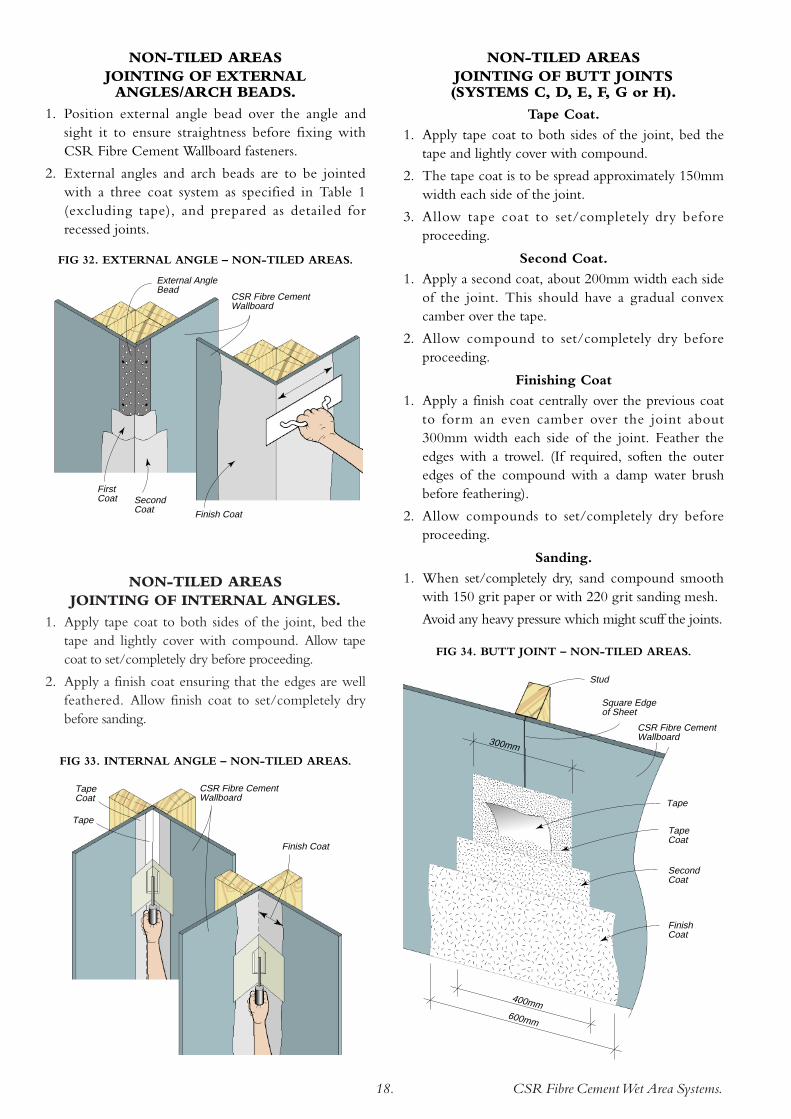
NON-TILED AREASJOINTING OF INTERNAL ANGLES.
1. Apply tape coat to both sides of the joint, bed thetape and lightly cover with compound. Allow tapecoat to set/completely dry before proceeding.
2. Apply a finish coat ensuring that the edges are wellfeathered. Allow finish coat to set/completely drybefore sanding.
Tape Coat
Tape
CSR Fibre CementWallboard
Finish Coat
FIG 33. INTERNAL ANGLE – NON-TILED AREAS.
FIG 32. EXTERNAL ANGLE – NON-TILED AREAS.
CSR Fibre CementWallboard
External AngleBead
First Coat Second
Coat Finish Coat
NON-TILED AREASJOINTING OF EXTERNALANGLES/ARCH BEADS.
1. Position external angle bead over the angle andsight it to ensure straightness before fixing withCSR Fibre Cement Wallboard fasteners.
2. External angles and arch beads are to be jointedwith a three coat system as specified in Table 1(excluding tape), and prepared as detailed forrecessed joints.
NON-TILED AREASJOINTING OF BUTT JOINTS(SYSTEMS C, D, E, F, G or H).
Tape Coat.
1. Apply tape coat to both sides of the joint, bed thetape and lightly cover with compound.
2. The tape coat is to be spread approximately 150mmwidth each side of the joint.
3. Allow tape coat to set/completely dry beforeproceeding.
Second Coat.
1. Apply a second coat, about 200mm width each sideof the joint. This should have a gradual convexcamber over the tape.
2. Allow compound to set/completely dry beforeproceeding.
Finishing Coat
1. Apply a finish coat centrally over the previous coatto form an even camber over the joint about300mm width each side of the joint. Feather theedges with a trowel. (If required, soften the outeredges of the compound with a damp water brushbefore feathering).
2. Allow compounds to set/completely dry beforeproceeding.
Sanding.
1. When set/completely dry, sand compound smoothwith 150 grit paper or with 220 grit sanding mesh.
Avoid any heavy pressure which might scuff the joints.
FIG 34. BUTT JOINT – NON-TILED AREAS.
300mm
Tape
Stud
Square Edgeof Sheet
CSR Fibre CementWallboard
400mm600mm
Tape Coat
Second Coat
Finish Coat
CSR Fibre CementWet Area Systems.19.
Decoration.Where regulations require an impervious finish, such
as to the walls adjoining or behind a bath, or for walls ofa shower recess, the CSR Fibre Cement Wallboard inthose areas must be finished with ceramic tiles.
Other areas must be painted or wallpapered.
PAINTING.For best results, the surface of CSR Fibre Cement
Wallboard should be primed with a high quality latexpr imer before painting. Paint manufacturers’instructions are to be followed in all cases.
WALLPAPERING.For best results, the surface of CSR Fibre Cement
Wallboard should be sealed with a pigmented oil base sealerbefore applying wallpaper or other decorative materials.
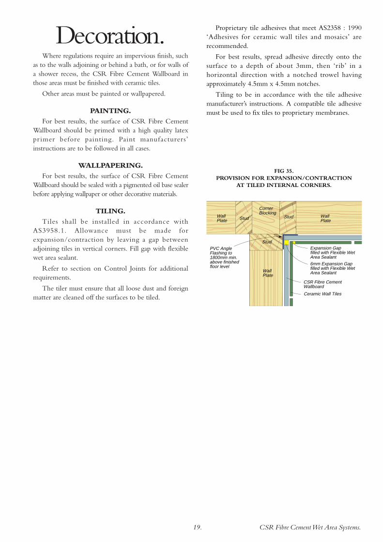
TILING.Tiles shall be installed in accordance with
AS3958.1. Allowance must be made forexpansion/contraction by leaving a gap betweenadjoining tiles in vertical corners. Fill gap with flexiblewet area sealant.
Refer to section on Control Joints for additionalrequirements.
The tiler must ensure that all loose dust and foreignmatter are cleaned off the surfaces to be tiled.
Ceramic Wall Tiles
CSR Fibre Cement Wallboard
Expansion Gapfilled with Flexible Wet Area Sealant
6mm Expansion Gapfilled with Flexible Wet Area Sealant
Stud Stud
Stud
Corner Blocking
WallPlate
WallPlate
WallPlate
PVC Angle Flashing to 1800mm min. above finished floor level
FIG 35. PROVISION FOR EXPANSION/CONTRACTION
AT TILED INTERNAL CORNERS.
Proprietary tile adhesives that meet AS2358 : 1990‘Adhesives for ceramic wall tiles and mosaics’ arerecommended.
For best results, spread adhesive directly onto thesurface to a depth of about 3mm, then ‘r ib’ in ahorizontal direction with a notched trowel havingapproximately 4.5mm x 4.5mm notches.
Tiling to be in accordance with the tile adhesivemanufacturer’s instructions. A compatible tile adhesivemust be used to fix tiles to proprietary membranes.

CSR Fibre CementWet Area Systems.20.
Description.CSR Fibre Cement Compressed Sheet can be fixed
directly to structural framing to form a strong andwater resistant flooring substrate for all domestic wetarea applications.
CSR Fibre Cement Compressed Sheet is acompressed, autoclaved, cellulose fibre reinforcedcement sheet.
CSR Fibre Cement Compressed Sheet is a dense,high strength, durable building product which isimpervious to water. It has a smooth flat surface and asquare edge finish.
Advantages.• Immune to permanent water damage and will not
rot.
• Lightweight and economical building material(when compared with concrete).
• Easy to install.
• Ideal for upper storey construction.
MaterialProperties.
CSR Fibre Cement Compressed Sheet conforms tothe requirements of AS2908.2 : 1992 ‘Cellulose-cementproducts Part 2: Flat sheets’.
Ignitability 0
Spread of Flame 0
Heat Evolved 0
Smoke Developed 0
FIRE HAZARD INDICES.
Thicknessmm
15
18
Width
mm90012009001200
1500✓✓✓✓
1800✓✓✓✓
2100✓✓
✓
2400✓✓✓✓
2700✓✓
3000✓✓✓✓
Length mm
Components.CSR Fibre Cement Compressed Sheet for flooring
applications is available in the following range of sizes:
FASTENERS.Nº10 x 50mm hot-dip galvanised steel or brass,
countersunk head wood screws.
ACCESSORIES.Flashing: Hypalon™ Flashing Strip, 130mm width.
Adhesive: HydrEpoxy™ 501.Mass 15mm thickness (nominal) 28kg/m2
Mass 18mm thickness (nominal) 34kg/m2
Length +0 to -3mm
Width +0 to -3mm
Thickness +10% to -0%
Diagonals Difference (max) 3mm
Edge Straightness Deviation (max) 1.5mm
MANUFACTURING TOLERANCES.
FIRE RESISTANCE.Under the Building Code of Australia, C1.1 Clause
2.5(e), CSR Fibre Cement is deemed to be non-combustible.
The Fire Hazard Properties, when tested inaccordance with AS1530.3 are as follows:
Compressed Sheet Wet Area Flooring System.
CSR Fibre CementWet Area Systems.21.
Installation.FIXING COMPRESSED SHEETS.
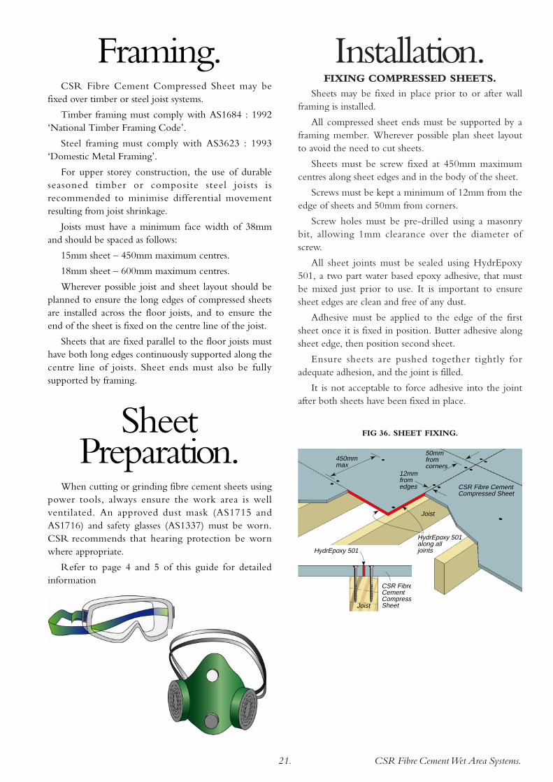
Sheets may be fixed in place prior to or after wallframing is installed.
All compressed sheet ends must be supported by aframing member. Wherever possible plan sheet layoutto avoid the need to cut sheets.
Sheets must be screw fixed at 450mm maximumcentres along sheet edges and in the body of the sheet.
Screws must be kept a minimum of 12mm from theedge of sheets and 50mm from corners.
Screw holes must be pre-drilled using a masonrybit, allowing 1mm clearance over the diameter ofscrew.
All sheet joints must be sealed using HydrEpoxy501, a two part water based epoxy adhesive, that mustbe mixed just prior to use. It is important to ensuresheet edges are clean and free of any dust.
Adhesive must be applied to the edge of the firstsheet once it is fixed in position. Butter adhesive alongsheet edge, then position second sheet.
Ensure sheets are pushed together tightly foradequate adhesion, and the joint is filled.
It is not acceptable to force adhesive into the jointafter both sheets have been fixed in place.
450mmmax
50mmfromcorners
HydrEpoxy 501 along all joints
CSR Fibre Cement Compressed Sheet
Joist
12mmfrom edges
HydrEpoxy 501
Joist
CSR FibreCementCompressSheet
FIG 36. SHEET FIXING.
Framing.CSR Fibre Cement Compressed Sheet may be
fixed over timber or steel joist systems.
Timber framing must comply with AS1684 : 1992‘National Timber Framing Code’.
Steel framing must comply with AS3623 : 1993‘Domestic Metal Framing’.
For upper storey construction, the use of durableseasoned timber or composite steel joists isrecommended to minimise differential movementresulting from joist shrinkage.
Joists must have a minimum face width of 38mmand should be spaced as follows:
15mm sheet – 450mm maximum centres.
18mm sheet – 600mm maximum centres.
Wherever possible joist and sheet layout should beplanned to ensure the long edges of compressed sheetsare installed across the floor joists, and to ensure theend of the sheet is fixed on the centre line of the joist.
Sheets that are fixed parallel to the floor joists musthave both long edges continuously supported along thecentre line of joists. Sheet ends must also be fullysupported by framing.
SheetPreparation.
When cutting or grinding fibre cement sheets usingpower tools, always ensure the work area is wellventilated. An approved dust mask (AS1715 andAS1716) and safety glasses (AS1337) must be worn.CSR recommends that hearing protection be wornwhere appropriate.
Refer to page 4 and 5 of this guide for detailedinformation

Continuous insitu membrane to shower recess floor, over angle and up walls
Shower Screen sealed with flexible sealant at floor and walls
150m
m m
in.
Non-ferrous Angle fixed to floor
75mm min.
Mortar bed
CSR Fibre Cement Compressed Sheet
CSR Fibre CementWet Area Systems.22.
Waterproofing.PERIMETER FLASHING.
Perimeter flashing must be used at the floor/walljunctions in all general wet areas, and must extend aminimum of 25mm above finished floor level.
Two recommended methods are:
PVC Flashing, 75 x 50mm adhesive fixed to flooronly using Fulaprene™ 303 Adhesive.
Hypalon™ Flashing Strip, 130mm wide, fixed tofloor only using HydrEpoxy™ 501.
Also refer to FIG 7, 8 and 9.
FIG 37. PERIMETER FLASHING.
PVC Perimeter Angle Flashing. Cut bottom flange, bend, overlap and bond to self and floor
Perimeter Angle Flashing Strip. Cut, bend, overlap and bond to self and floor
NOTE: At doorways, a brass or aluminium angleshould be fixed to the floor to support the flashing andprotect the tiles.
FIG 39. SHOWER RECESS WITH HOB.
Continuous insitu membrane to shower recess floor, over hob, and up walls
Shower Screen sealed with flexible sealant at hob and walls
50mmmin.
150m
m m
in.
Masonry Hob
Flexible Sealant
75mm min.
Mortar bed
CSR Fibre Cement Compressed Sheet
Wall sheeting
FIG 40. HOBLESS SHOWER RECESS.
FIG 38. DOORWAY FLASHING DETAIL.
Mortar bed
CSR Fibre Cement Compressed Sheet
Brass or aluminium Angle fixed to floor
Carpet and underlay
Door
Tiles
Perimeter Flashing
Joist
INSITU APPLIEDMEMBRANE.
A continuous insitu membranemust be applied to shower recess areasas shown in FIG 39 or 40.
For second storey installations, it isrecommended that a continuous insitumembrane be applied to the entire wetarea floor and up the walls to aminimum 150mm above the sheetlevel and/or to a minimum 50mmabove any shower hob.
NOTE: For further details onwaterproofing refer to AustralianStandard AS3740 : 1994.

CSR Fibre CementWet Area Systems.23.
PLUMBING WASTES.It is important that all plumbing
wastes are sealed, particularly in ashower recess.
A PVC waste yoke must be bondedto the flooring and the waste pipeusing HydrEpoxy™ 501 before fittinggrates and other fixtures.
A waste fitting incorporating a‘leak control system’ is recommendedto enable any moisture to drain frombeneath the floor tiles.
If a fall to waste is not required, tiles may be fixeddirectly to CSR Fibre Cement Compressed Sheet.
Tile adhesive must conform to Australian StandardAS2358 ‘Adhesives - for fixing ceramic tiles’.
If a fall to waste is required, tiles must be beddedinto a mortar bed which is not less than 12mm thick.
In all cases the tile and tile adhesive manufacturers’instructions should be followed.
FIG 41. WASTE DETAIL.
CSR Fibre Cement Compressed Sheet
Membrane continued into waste yoke
Waste grate with drainage slots
Waste Yoke bonded to compressed sheet and waste pipe
Tile Laying.

CSR Fibre CementWet Area Systems.24.
FC10
1.B
MS7
619.
0902
CSR Fibre Cement, CSR Limited A.C.N. 000 001 276. The following are trade marks of CSR Limited and are under license. Gyprock®.
CSR Fibre Cement Web Site.www.csrfibrecement.com.au
CSR designLINK® Technical Support Service.Telephone: 1800 621 117.
New South Wales and ACT.376 Victoria Street, Wetherill Park NSW 2164.
Telephone: (02) 9844 7944. Facsimile: (02) 9844 7877.
Queensland.768 Boundary Road, Coopers Plains QLD 4108.
Telephone: (07) 3212 6400. Facsimile: (07) 3212 6456.
Victoria.159 Wellington Road, Clayton VIC 3168.
Telephone: (03) 9265 4000. Facsimile: (03) 9265 4011.
South Australia.Lot 100 Sharp Court, Mawson Lakes SA 5095.
Telephone: (08) 8344 0666. Facsimile: (08) 8344 0644.
Western Australia.21 Sheffield Road, Welshpool WA 6106.
Telephone: (08) 9365 1666. Facsimile: (08) 9365 1656.
Tasmania.PO Box 61, Glenorchy TAS 7010.
Telephone: 0419 477 601. Facsimile: (03) 6249 2701.
Northern Territory.Lot 800 Stuart Highway, Berrimah NT 0828.
Telephone: (08) 8984 4070. Facsimile: (08) 8947 0034.
Guarantee.CSR Limited warrants its Fibre Cement products to be free of defects in materials and manufacture.
If a CSR product does not meet our standard, we will, at our option, replace or repair it, supply anequivalent product, or pay for doing one of these.
This warranty excludes all other warranties and liability for damage or loss in connection with defects inCSR's product, other than those compulsorily imposed by legislation, notably the Trade Practices Act.
Health & Safety. WARNING: Fibre Cement products contain crystalline silica. Repeated inhalation of fibre
cement dust may cause lung scarring (silicosis) or cancer. Do not breathe the dust. When cuttingsheets, use the methods recommended in this brochure to minimise dust generation.
If power tools are used, wear an approved dust mask (respirator).These precautions are not necessary when stacking, unloading or handling fibre cement products.
For further information and for a Material Safety Data Sheet, phone 1800 807 668.