Embed Size (px)
Citation preview

CSE5807 Wireless and Personal Area Networks
Lecture 2
Radio Communications Principles
Chapters 2,5 and 11 Stallings

Communications Channel Capacity
• Channel capacity is the maximum rate at which data can be transmitted over a given communication path or channel, under given conditions of:
– Bandwidth
– Noise
– Error rate
Communications Channel Capacity
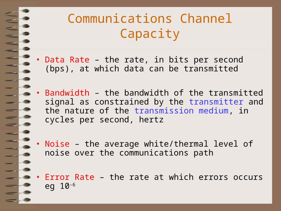
• Data Rate – the rate, in bits per second (bps), at which data can be transmitted
• Bandwidth – the bandwidth of the transmitted signal as constrained by the transmitter and the nature of the transmission medium, in cycles per second, hertz
• Noise – the average white/thermal level of noise over the communications path
• Error Rate – the rate at which errors occurs eg 10-6
Bandwidth
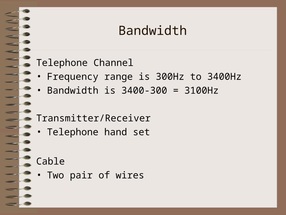
Telephone Channel
• Frequency range is 300Hz to 3400Hz
• Bandwidth is 3400-300 = 3100Hz
Transmitter/Receiver
• Telephone hand set
Cable
• Two pair of wires
Nyquist Bandwidth
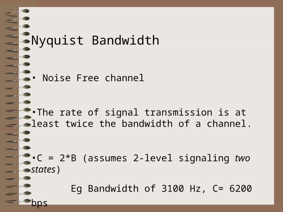
• Noise Free channel
•The rate of signal transmission is at least twice the bandwidth of a channel.
•C = 2*B (assumes 2-level signaling two states)
Eg Bandwidth of 3100 Hz, C= 6200 bps

Nyquist Bandwidth
•Multi-level signaling (M, more than two states)
• C = 2Blog2M
• Eg Bandwidth of 3100 Hz and M = 64,
C= 6200*log264 = 37200 bps

Nyquist Bandwidth
+ More signaling levels = more data carried each signal interval
- Noise and transmission system effects become more serious as M increases
Shannon
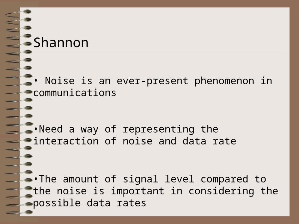
• Noise is an ever-present phenomenon in communications
•Need a way of representing the interaction of noise and data rate
•The amount of signal level compared to the noise is important in considering the possible data rates
Shannon
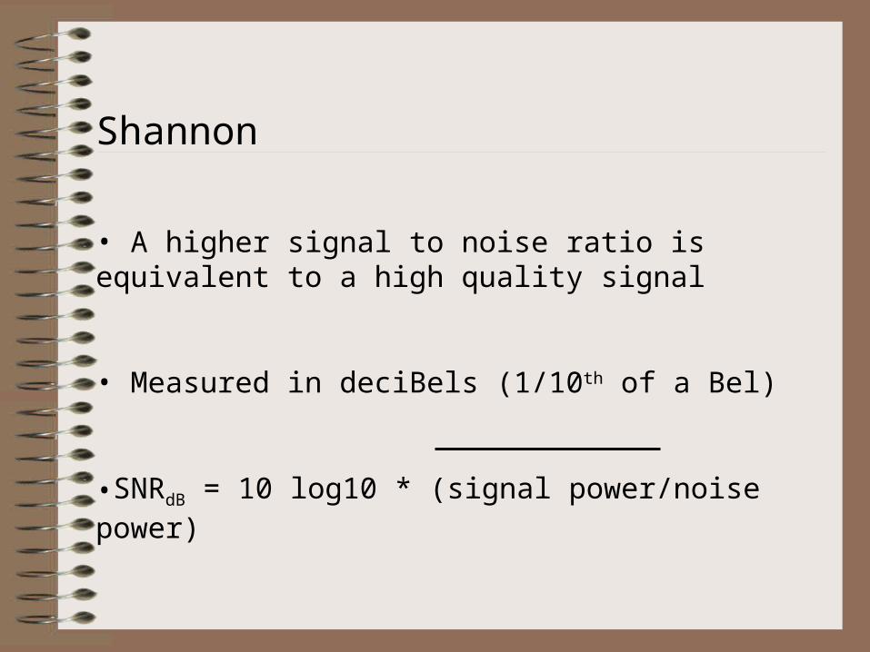
• A higher signal to noise ratio is equivalent to a high quality signal
• Measured in deciBels (1/10th of a Bel)
•SNRdB = 10 log10 * (signal power/noise power)

Shannon
• Maximum channel capacity (taking signal to noise ratio into account):
• C = Blog2 (1+SNR)
Gain/Loss Measurement
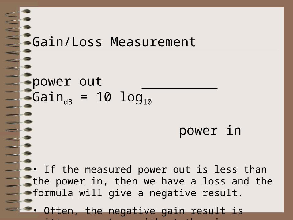
power out GaindB = 10 log10 power in
• If the measured power out is less than the power in, then we have a loss and the formula will give a negative result.
• Often, the negative gain result is written as a Loss without the sign.

Gain/Loss Measurement
power out GaindBm = 10 log10 1mW
Antenna Systems
• An antenna is a device that is used for radiating and/or collecting electromagnetic energy
• A receiving antenna may be one or more conductors that have electrical energy induced in them by the passage of Electro Magnetic Radiation
•A transmitting antenna causes EMR due to the electrical energy in the antennas conductor(s)

Antenna Systems
• An antenna will radiate power in all directions but, typically, does not performance equally well in all directions
• A common way to characterize the performance of an antenna is the radiation pattern

Isotropic Antenna (Idealised)
Omnidirectional - A point source that radiates power in all directions equally – fig 5.1(a)
Directional - preferred direction of radiation along one axis – fig 5.1(b)
Relative Power
• To determine relative power in a given direction a line is drawn from the antenna position at the appropriate angle, and the point of intercept with the radiation pattern is determined

Relative Power
• Fig 5.1 shows a comparison of two transmission angles, A and B.• Fig 5.1(a) vectors A and B of equal length• Fig 5.1(b) vector B is longer then vector A• Comments ?
Beam Width
• When we measure the directivity of an antenna, we often describe this as the beam width. It is the angle within which the power radiated by the antenna is focused
• This is usually found by measuring the power in the preferred direction and then discovering where this power level drops to half the value of the preferred direction

Reception Pattern
When an antenna is used for reception the radiation pattern becomes a reception pattern

Antenna Wavelength
We usually measure the antenna by its wavelength λ
This is calculated using the following formula
λ = where v is the speed of light
3 x 10⁸ m/sf
v

Antenna Wavelength
• Frequency of transmission f = 12 GHz
• V = 3 x 10⁸ metres/second
• Wavelength λ = 3 x 10⁸ /12 x 109
=- 0.025 metres
Antenna Types - Dipoles
Half-wave dipole
• Consists of two straight collinear conductors of equal length, separated by a small gap
• The length of the antenna is one half the wavelength of the signal that can be transmitted most efficiently
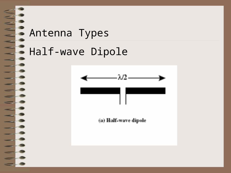
Antenna Types
Half-wave Dipole

Antenna Types - Dipoles
Quarter-wave dipole
• A vertical quarter wave antenna is the type commonly used for car and portable radios

Antenna Types
Quarter-wave antenna
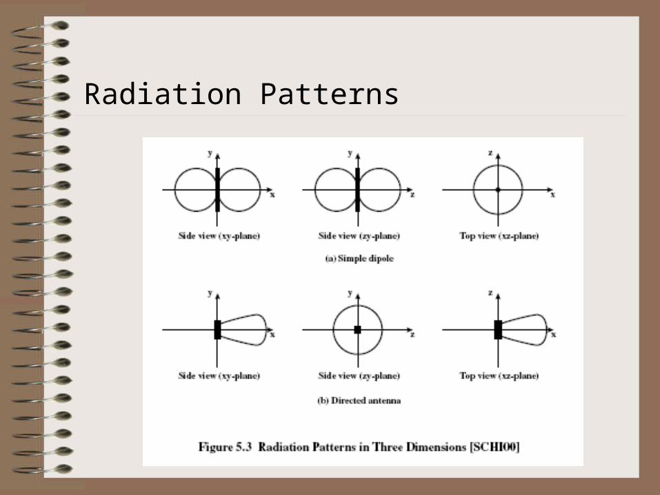
Radiation Patterns

Antenna Types
Parabolic Antenna
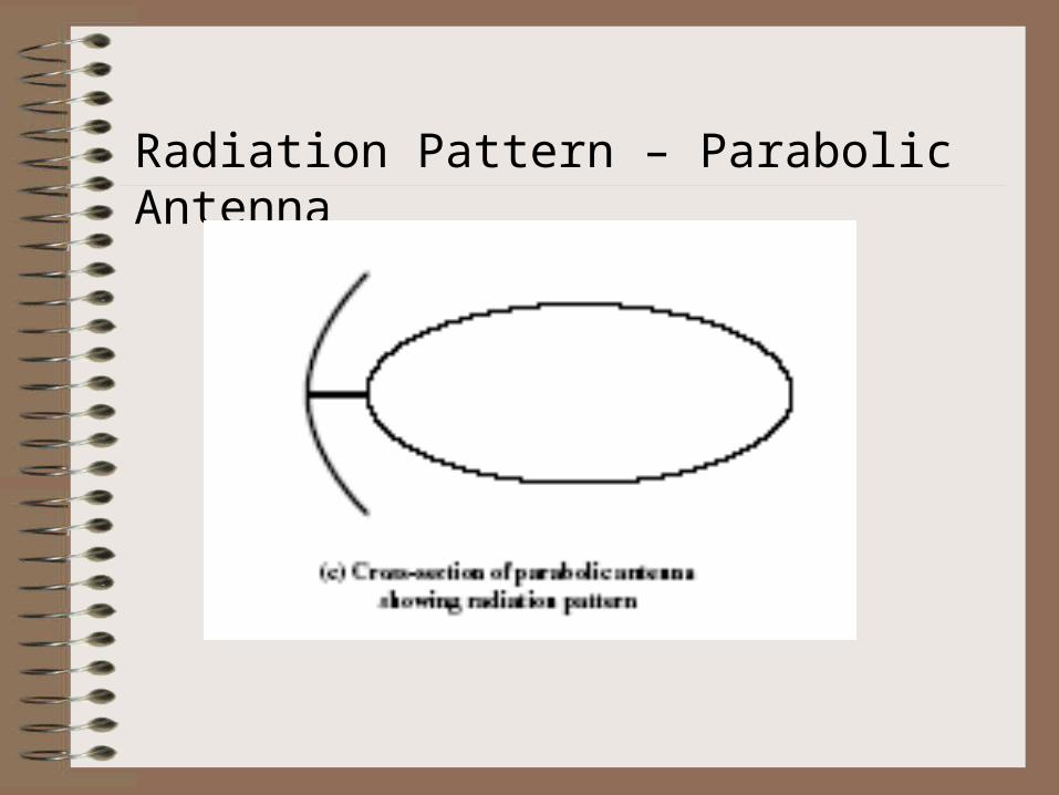
Radiation Pattern – Parabolic Antenna

Antenna Gain• Is a measure of the directionality of an antenna.
• Antenna gain is defined as the power output, in a particular direction compared to that produced in any direction by a perfect isotropic omnidirectional antenna
• If an antenna has a gain of 3dB, that antenna improves on the isotropic antenna in that direction by 3dB, or a factor of 2 (100.3)
• The increased power radiated in a given direction is at the expense of other directions

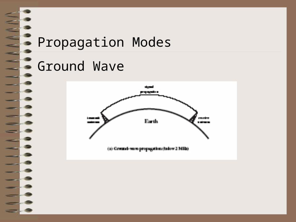
Propagation Modes – Ground Wave
• Follows contour of the earth, can propagate considerable distances
• The electromagnetic wave induces a current in the earth’s surface, the result of which is to slow the wave front near the earth , causing the wave front to tilt downward and hence follow the earth’s curvature
• AM Radio
• Below 2MHz
Propagation Modes
Ground Wave

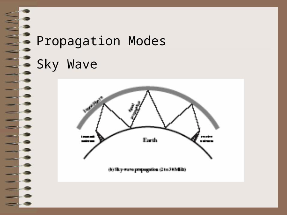
Propagation Modes – Sky Wave
• A signal from an earth based antenna is reflected from the ionized layer of the upper atmosphere back down to earth
• Signal can travel through a number of hops, bouncing back and forth
• Signal can be picked up thousands of kms from transmitter
• CB radio, BBC
• 2 to 30MHz
Propagation Modes
Sky Wave
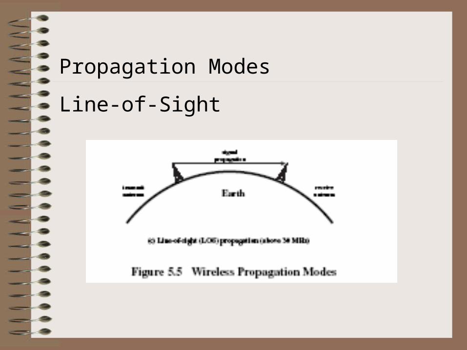
Propagation Modes – Line of Sight
• Above 30MHz neither ground nor sky wave propagation operate
• Signal can be transmitted between earth station and satellite overhead that is not beyond the horizon
• For ground based communication transmitting and receiving antennas must be within an effective line of sight of each other
Propagation Modes – Line of Sight
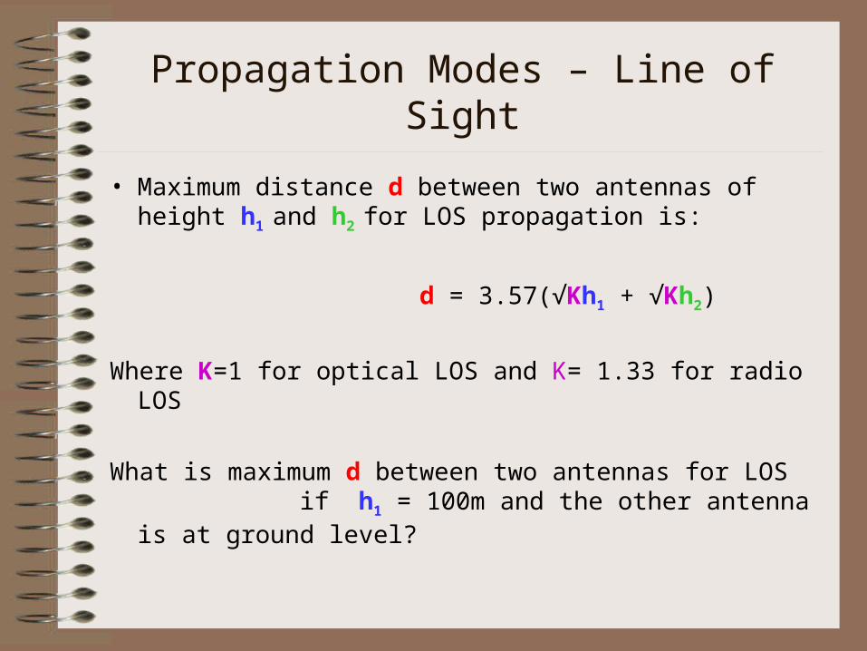
• Maximum distance d between two antennas of height h1 and h2 for LOS propagation is:
d = 3.57(√Kh1 + √Kh2)
Where K=1 for optical LOS and K= 1.33 for radio LOS
What is maximum d between two antennas for LOS if h1 = 100m and the other antenna is at ground level?
Propagation Modes
Line-of-Sight

Propagation Modes
Refraction
Polarization
• The polarization of an antenna is the orientation of the electric field of the radio wave with respect to the Earth's surface and is determined by the physical structure of the antenna and by its orientation.
• A simple straight wire antenna will have one polarization when mounted vertically, and a different polarization when mounted horizontally
Polarization
• For line-of-sight communications for which polarization can be relied upon, it can make a large difference in signal quality to have the transmitter and receiver using the same polarization
• Many tens of dB difference are commonly seen and this is more than enough to make the difference between reasonable communication and a broken link.
Diversity Antenna Systems
Using two antennas located a distance apart can counteract the effect of signal loss due to propagation problems.

Transmission Problems
Attenuation and Attenuation Distortion
Free Space Loss
Noise
Atmospheric Absorption
Multipath
Refraction
Transmission Problems - LOS
Fresnel Zone
The higher the frequency of the transmission, the more it may be affected by obstructing objects. The possible interference is determined by computing the Fresnel Zone
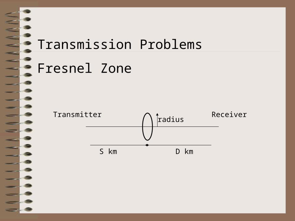
Transmission Problems
Fresnel Zone
Transmitter Receiverradius
S km D km
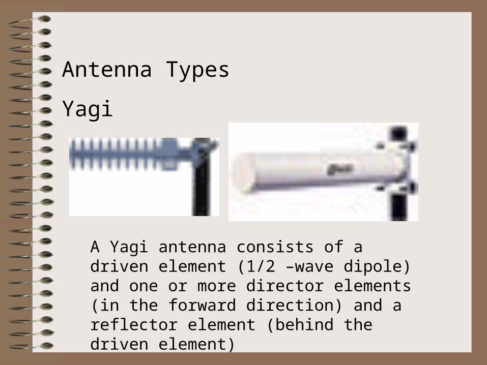
Antenna Types
Yagi
A Yagi antenna consists of a driven element (1/2 –wave dipole) and one or more director elements (in the forward direction) and a reflector element (behind the driven element)


![ZLHU]FKRáNRZD · 2015. 3. 16. · 2% 2% 2,5% 2,5% 2,5% 2,5% 2,5% 2,5% 2,5% 2% 2% 2% 2,5% 2% 2% 2,5% 2,5% 2% 2% 2% 2,5% 2,5% 2,5% 2% 2% 2% 2% 2% 2,5% 2,5% 2% 2,5% 2,5% 2% 2,5% 2,5%](https://img.dokumen.tips/doc/110x75/60c54f29043e263fdb1257bd/zlhufkr-2015-3-16-2-2-25-25-25-25-25-25-25-2-2-2-25.jpg)


![Monash Universityusers.monash.edu/~azaslavs/cse5807/stallings-ch15...qûnotll IllJasn aplAo.1d s10ded ÛUIA\OIIOJ .10J saoanos poofi [17081 AID] pooô an pue JO an illoq JO poofi aplA0Jd](https://img.dokumen.tips/doc/110x75/60c6fd51000ff052c74eb912/monash-azaslavscse5807stallings-ch15-qnotll-illjasn-aplao1d-s10ded-uiaoiioj.jpg)

![ZLHU]FKRáNRZD · 2015. 3. 16. · 2,5% 2,5% 2,5% 2,5% 2,5% 2,5% 2,5% 2,5% 2,5% i zm% 2,5% 2% 2% 2% 2% 2% 2% 2% 2% 2,5% 2% 2% 2% 2,5% 2,5% 2% 2% 2% 2% 2% 2% 2% 2% 2% 2,5% i zm% 2,5%](https://img.dokumen.tips/doc/110x75/60c55272bda9cd16943ecc8f/zlhufkr-2015-3-16-25-25-25-25-25-25-25-25-25-i-zm-25.jpg)


![Sistemi Operativi [William Stallings]](https://img.dokumen.tips/doc/110x75/543cd117b1af9fc42e8b4811/sistemi-operativi-william-stallings.jpg)