Embed Size (px)
Citation preview
CSE241 1
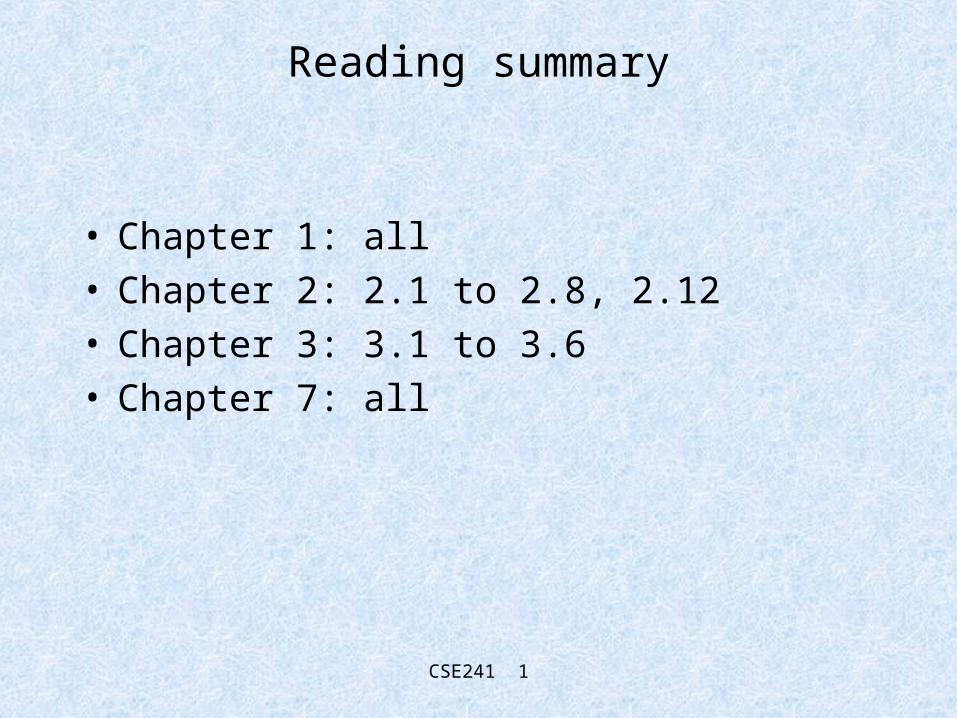
Reading summary
• Chapter 1: all• Chapter 2: 2.1 to 2.8, 2.12• Chapter 3: 3.1 to 3.6• Chapter 7: all
CSE241 2
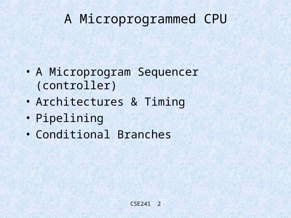
A Microprogrammed CPU
• A Microprogram Sequencer (controller)• Architectures & Timing• Pipelining• Conditional Branches

CSE241 3
Current Situation
Address Register
Microprogram memory
MUX
Data Path
MicroinstructionsTo Data Path
Condition Codes
CSE241 4
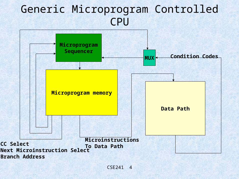
Generic Microprogram Controlled CPU
Microprogram memory
MUX
Data Path
MicroinstructionsTo Data Path
Condition Codes
MicroprogramSequencer
CC SelectNext Microinstruction SelectBranch Address

CSE241 5
Simplified Generic Microprogram Sequencer
Branch Address (Input)
Next MicroinstructionSelect (Input)Condition
Code (Input)
multiplexer
Microprogram Counter
Incrementer
‘0’ (Zero)(internal)
Next Microinstruction
Select Logic
Address Out
clock

CSE241 6
Sequencer Functions
• SEQ– Next microinstruction address is microPC (PC)
• BZ– Next microinstruction address is 0
• BU k– Next microinstruction address is from branch address
field
• BC k– Branch to k if CC is true, else next microinstruction
address is from PC

CSE241 7
Behaviour of PC • Notice that
– The PC always latches the output of the incrementer at the start of every new clock cycle
– The output of the incrementer (combinational logic) is always the value of the output of the device (the instruction address) + 1
– So the PC at the start of the next clock cycle will always contain the address of the instruction located in the next sequential memory location located following the address of the instruction being output by the device
• So, if the device is emitting k, the PC in the next clock cycle will have the value k+1, no matter how k was chosen (Branch address, SEQ etc).

CSE241 8
SEQ
ConditionCode (Input)
Branch Address (Input)
Next MicroinstructionSelect (Input)
multiplexer
Microprogram Counter
Incrementer
‘0’ (Zero)(internal)
Next Microinstruction
Select Logic
Address Out
clockK
K
K
K
K + 1

CSE241 9
SEQ (makes certain assumptions which may not hold in practice)
PC
MUX output
Device Output
IncrementerOutput
k (is stable, because PC is a register)
Select PC (== k); stable because output is from PC
k (is stable, because PC is a register)
Device output + 1 == k+1K+1 latched by
PC
K+1

CSE241 10
BZ (Branch to Zero)
Branch Address (Input)
Next MicroinstructionSelect (Input)
multiplexer
Microprogram Counter
Incrementer
‘0’ (Zero)(internal)
Next Microinstruction
Select Logic
Address Out
clockK
0
0
0
0 + 1 = 1

CSE241 11
BZ (timing) (makes certain assumptions which may not hold in practice)
PC
MUX output
Device Output
IncrementerOutput
k (is stable, because PC is a register)
0 -- MUX output is the Zero input
0
Device output + 1 == 0+1 = 11 latched by
PC
1

CSE241 12
BU d (Branch Unconditionally to d)
Branch Address (Input)
Next MicroinstructionSelect (Input)
multiplexer
Microprogram Counter
Incrementer
‘0’ (Zero)(internal)
Next Microinstruction
Select Logic
Address Out
clockk
d
d
d
d + 1

CSE241 13
BU d (timing) (makes certain assumptions which may not hold in practice)
PC
MUX output
Device Output
IncrementerOutput
k (is stable, because PC is a register)
d (the value on the BA field)
d
Device output + 1 == d+1X+1 latched by
PC
d+1
CSE241 14
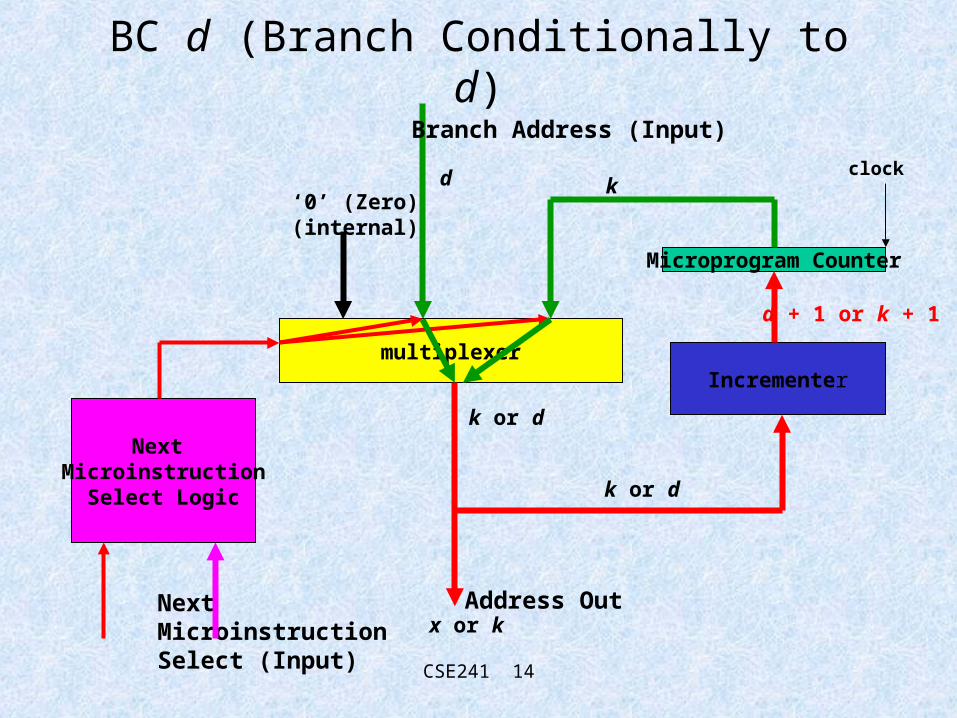
BC d (Branch Conditionally to d)
Branch Address (Input)
Next MicroinstructionSelect (Input)
multiplexer
Microprogram Counter
Incrementer
‘0’ (Zero)(internal)
Next Microinstruction
Select Logic
Address Out
clockk
k or d
x or k
k or d
d + 1 or k + 1
d

CSE241 15
BC d (timing) (makes certain assumptions which may not hold in practice)
PC
MUX output
Device Output
IncrementerOutput
X+1 or K+1k (is stable, because PC is a register)
Depends on value of CC; may be X (CC true) or K (CC False)
k or d
Device output + 1 == d+1 or k+1X+1 or
K+1latched by
PC

CSE241 16
Architecture 1
The green box contains the “generic microprogramsequencer.
The microinstruction contains the following (Control Path) fields:-
1. Next Microinstruction Select (seq, BZ, BU K, BC K)2. Branch Address3. CCMUX Select

CSE241 17
Timing in Architecture 1
Start with the output of thesequencer
2: Microinstruction Fetch
3: Simultaneous executionof microinstrutions in Data Pathand Control Path
ConditionCodesGenerated
Condition Code available to Microprogram Sequencer

CSE241 18
Timing of SEQ, Architecture 1 (makes certain assumptions which may not hold in practice)
PC
Sequenceroutput
incrementer
Memory
Data Path
CC’s
CCMUXselect
next instselect
k
k
k+1
inst[k]
executing inst[k]
Choose CCx
SEQ
execution finished;CC’s valid
k+1 latched by PC
k+1
fetch inst[k]
CSE241 19
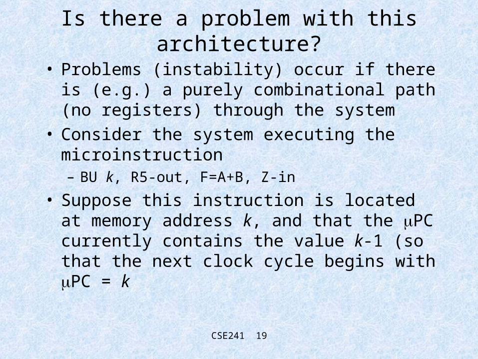
Is there a problem with this architecture?
• Problems (instability) occur if there is (e.g.) a purely combinational path (no registers) through the system
• Consider the system executing the microinstruction– BU k, R5-out, F=A+B, Z-in
• Suppose this instruction is located at memory address k, and that the PC currently contains the value k-1 (so that the next clock cycle begins with PC = k

CSE241 20
The architecture (reminder)Note:the path(s) from
--Branch Address in--next inst. select in--through MUX--through memory--back up to sequencer
are purely combinational. No registersare involved.
CSE241 21
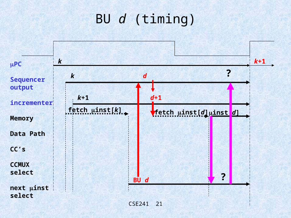
BU d (timing)
PC
Sequenceroutput
incrementer
Memory
Data Path
CC’s
CCMUXselect
next instselect
k
k
k+1
BU d
k+1
fetch inst[k]
d
d+1
fetch inst[d] inst[d]
?
?

CSE241 22
The problem
• The problem is this:-– when the inst at k is fetched, it contains the operation “BU d”
(branch unconditional to d)
– so the output of the sequencer MUX changes from the PC (==k) to the value on the BA field (==d)
– so the inst at k will stop executing because
– the memory fetches the inst at d; but what is the next microinstruction select field in this inst? What if it contains BU x?
• Generally, we need to stabilize something
• We cannot permit this uncontrolled multifetching
CSE241 23
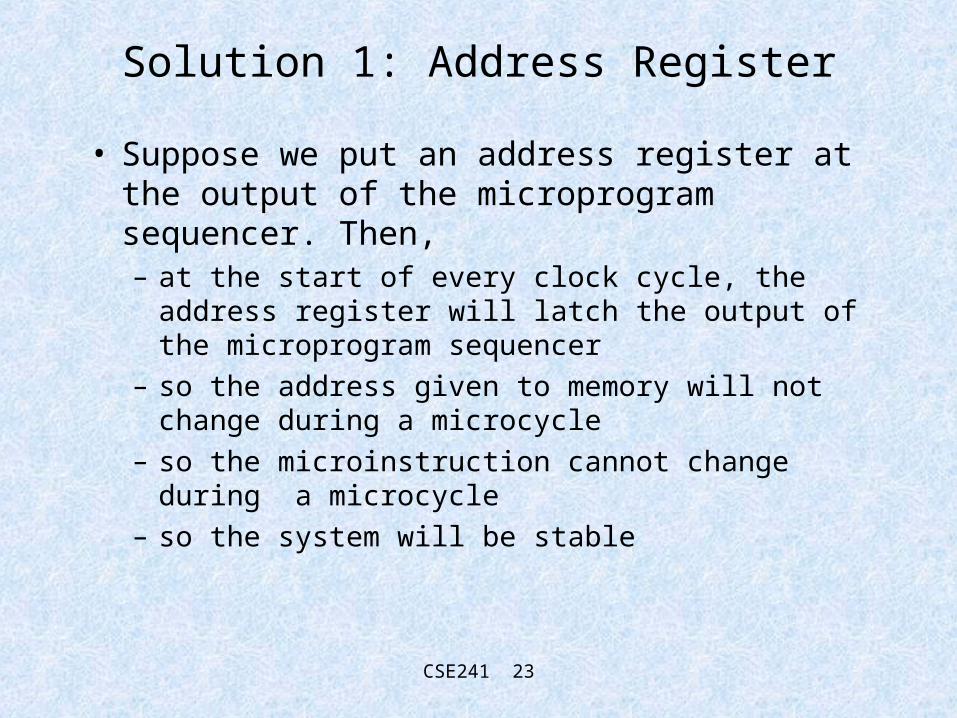
Solution 1: Address Register
• Suppose we put an address register at the output of the microprogram sequencer. Then,– at the start of every clock cycle, the address register
will latch the output of the microprogram sequencer
– so the address given to memory will not change during a microcycle
– so the microinstruction cannot change during a microcycle
– so the system will be stable

CSE241 24
Address Based Architecture
Sequencer
Address Register
Microprogram memoryData Path
CC Mux

CSE241 25
SEQ Timing on Address based architecture
Sequencer
Address Register
Microprogram memoryData Path
CC Mux
Start with address register(==k)
Fetch inst[k]inst[k] is applied to both the Control Path and Data Path
Next microinstruction addressis generated by sequencer and made ready at input of addressregister
CSE241 26
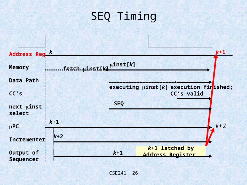
SEQ Timing
Address Reg
Memory
Data Path
CC’s
next instselect
PC
Incrementer
Output ofSequencer
k
k+2
inst[k]
executing inst[k]
k+1
execution finished;CC’s valid
k+1 latched byAddress Register
k+1
fetch inst[k]
k+1
SEQ
k+2

CSE241 27
BU X timing
Address Reg
Memory
Data Path
CC’s
next instselect
PC
Incrementer
Output ofSequencer
k -- note that this is stable!!!
k+2
inst[k]
executing inst[k]
d
execution finished;CC’s valid
d+1 latched by PC
d
fetch inst[k]
k+1
BU d
d+1

CSE241 28
Address-Based Architecture
• Convince yourself that this is a stable architecture• Note that the order of timing is
– fetch the microinstruction at address M[address register]
– execute this microinstruction
• So the total microcycle time T is– T = tf + te where tf = fetch time and te = execute time

CSE241 29
Pipelined Architecture
• Important alteration in the architecture• There are ramifications we will not bother with
(e.g., behaviour of conditional branches)• Very important architectural construct
– pipelining is everywhere!

CSE241 30
Pipelined Architecture
Sequencer
Microprogram memory
Data Path
CC Mux
Pipeline Register
CSE241 31
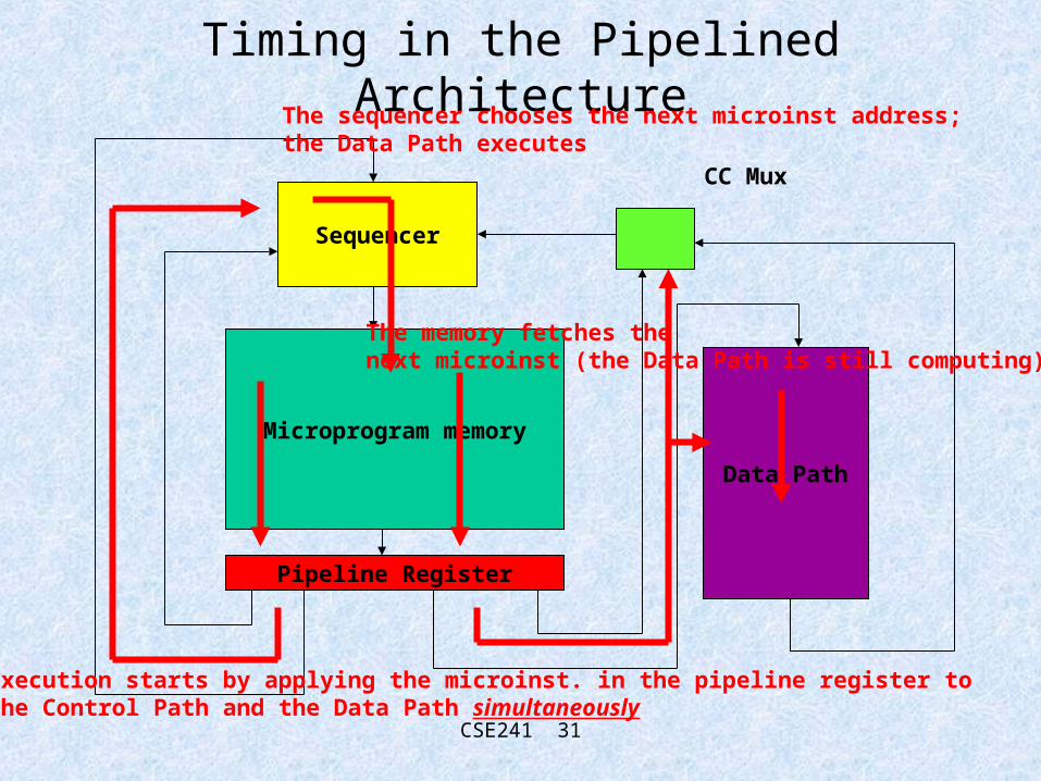
Timing in the Pipelined Architecture
Sequencer
Microprogram memory
Data Path
CC Mux
Pipeline Register
Execution starts by applying the microinst. in the pipeline register tothe Control Path and the Data Path simultaneously
The sequencer chooses the next microinst address;the Data Path executes
The memory fetches thenext microinst (the Data Path is still computing)

CSE241 32
SEQ Timing in the Pipelined Architecture
Pipeline Reg
next instselect
PC
Incrementer
Output ofSequencer
Memory
Data Path
microinstruction[t] (t is time; we don’t know where this came from
executing inst[t]
k+1
execution finished;
k+1 latched by PC
k+1k
SEQ
k
Fetch inst[k] inst[k] fetched, and can be latched by pipeline register inst[k] latched by
pipeline register

CSE241 33
Pipelining
• has– overlapped the microinstruction fetch and execute
– thus the total microcycle time has become• T = Max(tf , te)
– compare this to• T = tf + te