Embed Size (px)
Citation preview

1
CSE 237A Interfacing, Sensors &
ControlTajana Simunic RosingDepartment of Computer Science and EngineeringUniversity of California, San Diego.

2Fall 2005
Hardware platform architecture

3
Sensors & Actuators

4
Embedded System Hardware
5
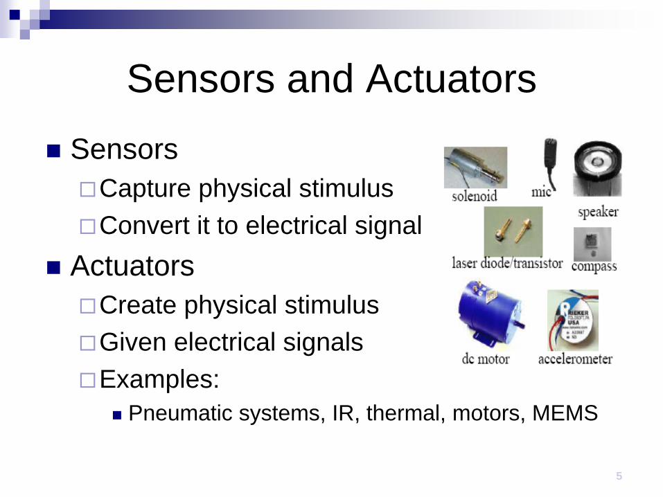
Sensors and Actuators SensorsCapture physical stimulusConvert it to electrical signal
ActuatorsCreate physical stimulus Given electrical signalsExamples:
Pneumatic systems, IR, thermal, motors, MEMS
6
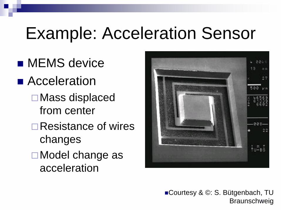
Example: Acceleration Sensor
Courtesy & ©: S. Bütgenbach, TU Braunschweig
MEMS device AccelerationMass displaced
from centerResistance of wires
changesModel change as
acceleration

7
Charge-coupled devices (CCD)
Based on charge transfer to next pixel cell

8
Example: Biometrical SensorsExample: Fingerprint sensor (© Siemens, VDE):
Matrix of 256 x 256 elements
Voltage ~ Distance
Resistance computed.
Integrated into ID mouse.

9Fall 2005
10
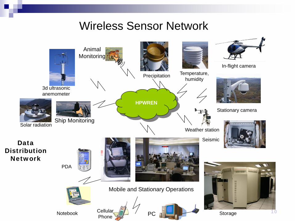
PDA
3d ultrasonic anemometer
Temperature, humidity
HPWREN
Animal Monitoring
Notebook Cellular Phone PC
Ship Monitoring
Wireless Sensor Network
Data Distribution
Network
Precipitation
Solar radiation
In-flight camera
Weather station
Mobile and Stationary Operations
Stationary camera
Seismic
Storage

11
Actuators
Microsystems motor
(© MCNC)

Stepper Motor
Stepper motor: rotates fixed number of degrees when given a “step” signal.
In contrast, DC motor just rotates when power applied.
Rotation achieved by applying specific voltage sequence to coils
Controller greatly simplifies this
http://www.cise.ufl.edu/~prabhat/Teaching/cis6930-f04/comp4.pdf
Secure Hardware Security needed for communication and storage Demand for special equipment for cryptographic keys To resist side-channel attacks
Measurements of the supply current Electromagnetic radiation
Special mechanisms for physical protection shielding, sensors for detecting tampering with the modules
Logical security using cryptographic methods. Smart cards: special case of secure hardware
Have to run with a very small amount of energy.

14
actuators
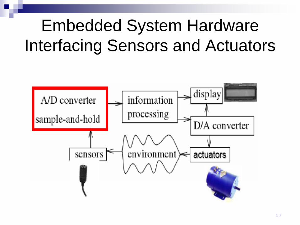
Embedded System HardwareInterfacing Sensors and Actuators

Output Output devices of embedded systems include
Displays, audio Electro-mechanical devices: these influence the
environment through motors and other electro-mechanical equipment. May require analog output.
Naming convention:

Digital-to-Analog (D/A) Converters
Various types, can be quite simple, e.g.:
17
Embedded System HardwareInterfacing Sensors and Actuators

18
Sample and Hold
Digital information processing; Discrete time; sample and hold-devices.Ideally: width of clock pulse -> 0
Ve is a mapping ℝ→ ℝ

19
Analog-to-digital converters
proportionality
Vmax = 7.5V
0V
11111110
0000
0010
0100
0110
1000
1010
1100
0001
0011
0101
0111
1001
1011
1101
0.5V1.0V1.5V2.0V2.5V3.0V
3.5V4.0V4.5V5.0V
5.5V6.0V6.5V7.0V
analog to digital
4
3
2
1
t1 t2 t3 t40100 1000 0110 0101
time
anal
og in
put (
V)
Digital output
digital to analog
4
3
2
1
0100 1000 0110 0101
t1 t2 t3 t4time
anal
og o
utpu
t (V
)
Digital input

20
Quantization Noise quantization noise = approx - real signal
* [http://www.beis.de/Elektronik/DeltaSigma/DeltaSigma.html]

21
Frequency spectrum of sampled signal Let Xc(): frequency
spectrum of the continuous signal, cut-off frequency ΩN=2π fN
Let Ωs=2π fs: sampling frequency
Let Xs: frequency spectrum of the sampled signal
Xs consists of multiple copies of Xc, separated by Ωs
Cannot be distinguished in sampled signal

22
Aliasing
If Ωs < ΩN/2 copies of spectrum overlap
No problem for signal reconstruction if this is avoided.

23Fall 2005
Nyquist theorem
Analog input to sample-and-hold can be precisely reconstructed from its output, provided that sampling proceeds at ≥ double of the highest frequency found in the input voltage [Nyquist 1928, Shannon, 1949]
S/H A/D-converter D/A-converter= ?
Inter-polate
Does not capture effect of value quantization:Quantization noise prevents precise reconstruction.
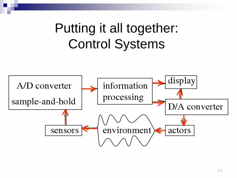
24
Putting it all together: Control Systems

25
Control System Objective: output tracks a reference even in the presence
of measurement noise, model error and disturbances Metrics
Stability - Output remains bounded Performance - How well an output tracks the reference Disturbance rejection Robustness - Ability to tolerate modeling error of the plant
E.g: Cruise control, Thermostat, Aircraft altitude control

26
Performance Rise time
Time it takes form 10% to 90%
Peak time Overshoot
Percentage by which Peak exceed final value
Settling time Time it takes to
reach 1% of final value
27
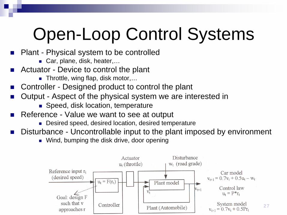
Open-Loop Control Systems Plant - Physical system to be controlled
Car, plane, disk, heater,… Actuator - Device to control the plant
Throttle, wing flap, disk motor,… Controller - Designed product to control the plant Output - Aspect of the physical system we are interested in
Speed, disk location, temperature Reference - Value we want to see at output
Desired speed, desired location, desired temperature Disturbance - Uncontrollable input to the plant imposed by environment
Wind, bumping the disk drive, door opening

28
Closed Loop Control Systems Sensor
Measure the output Error detector Feedback control systems Minimize tracking error
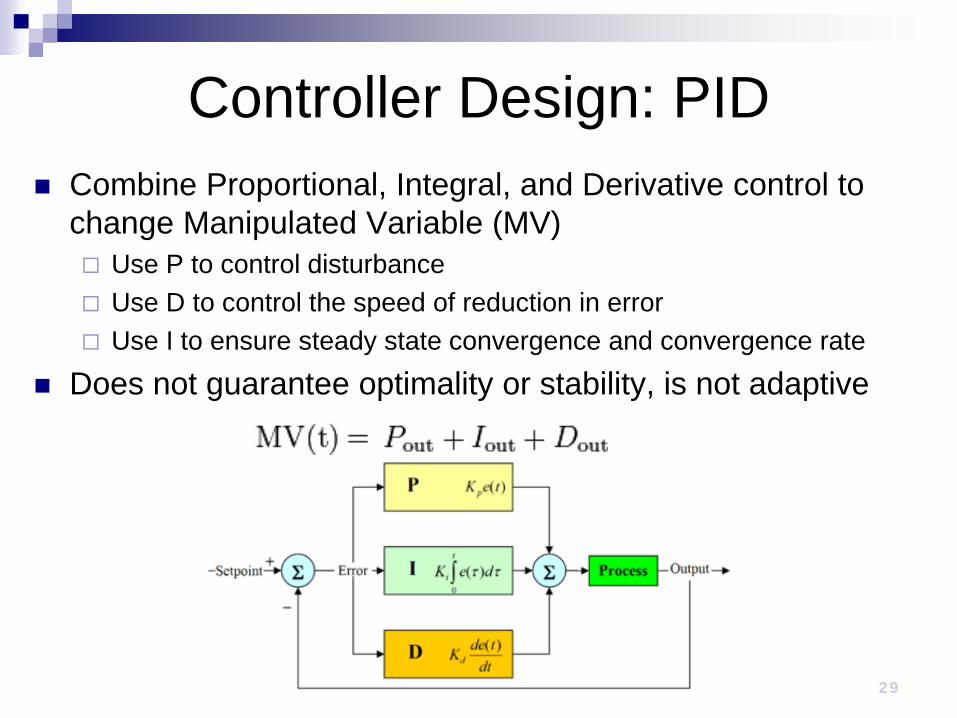
29
Controller Design: PID Combine Proportional, Integral, and Derivative control to
change Manipulated Variable (MV) Use P to control disturbance Use D to control the speed of reduction in error Use I to ensure steady state convergence and convergence rate
Does not guarantee optimality or stability, is not adaptive

Controller design - P Make a change to the output that
is proportional to the current error Pout: Proportional term of output Kp: Proportional gain e: Error
P controller will not settle at the final target value retains error that depends on Kp and
the process gain
System can become unstable when Kp is too high
30

Controller Design: Integral Proportional to both the
magnitude of the error and the duration of the error
Large Ki eliminates steady state errors faster but can cause overshot
31
Iout

32
Controller Design: Derivative Reduces the magnitude
of the overshoot produced by the integral component and improves the combined controller-process stability
Large Kd decreases the overshot but amplifies the noise in the signal

33
Controller Design: PID Tuning the controller Effects of increasing parameters
Parameter
Rise Time
Overshoot
Settling Time
S.S. Error
Kp Decrease Increase Small Change Decrease
Ki Decrease Increase Increase Eliminate
KdSmall
Decrease Decrease Decrease None

34
Interfacing

35Fall 2005
Hardware platform architecture
36Fall 2005
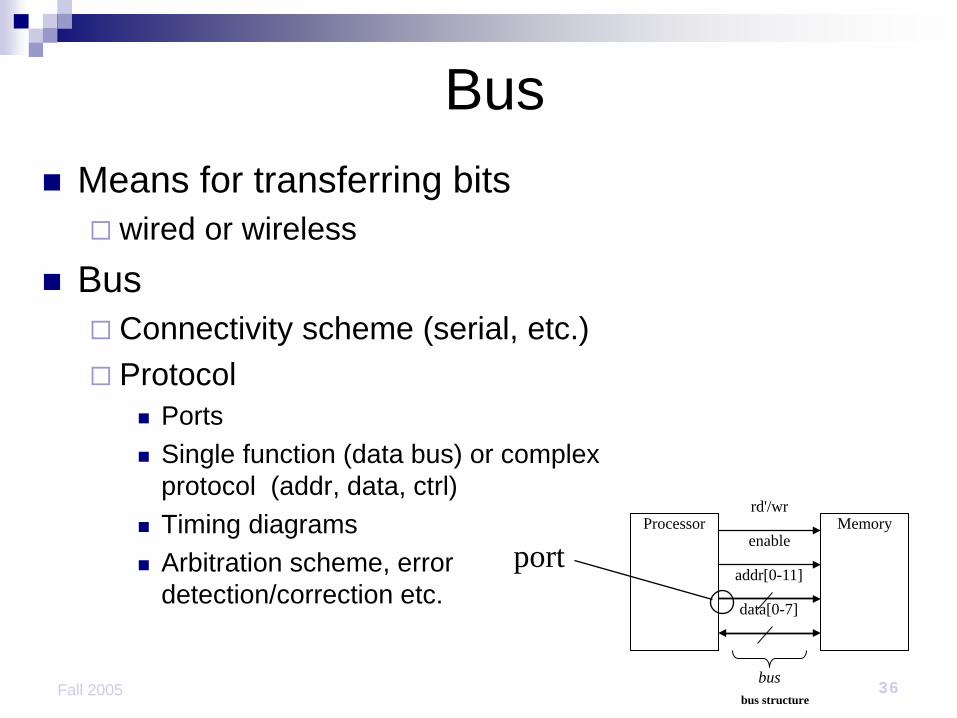
Bus
bus structure
Processor Memoryrd'/wr
enable
addr[0-11]
data[0-7]
bus
Means for transferring bits wired or wireless
Bus Connectivity scheme (serial, etc.) Protocol
Ports Single function (data bus) or complex
protocol (addr, data, ctrl) Timing diagrams Arbitration scheme, error
detection/correction etc.port
37Fall 2005
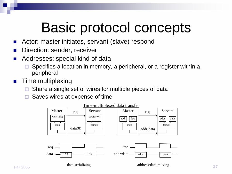
Basic protocol concepts Actor: master initiates, servant (slave) respond Direction: sender, receiver Addresses: special kind of data
Specifies a location in memory, a peripheral, or a register within a peripheral
Time multiplexing Share a single set of wires for multiple pieces of data Saves wires at expense of time
data serializing address/data muxing
Master Servantreq
data(8)
data(15:0) data(15:0)
mux demux
Master Servantreq
addr/data
req
addr/data
addr data
mux demux
addr data
req
data 15:8 7:0 addr data
Time-multiplexed data transfer
38Fall 2005
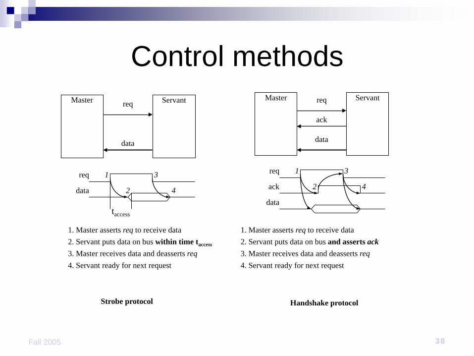
Control methods
Strobe protocol Handshake protocol
Master Servantreq
ack
req
data
Master Servant
data
req
data
taccess
req
data
ack
1. Master asserts req to receive data2. Servant puts data on bus within time taccess
1
2
3
4
3. Master receives data and deasserts req4. Servant ready for next request
1
2
3
4
1. Master asserts req to receive data2. Servant puts data on bus and asserts ack3. Master receives data and deasserts req4. Servant ready for next request

39Fall 2005
Microprocessor interfacing Port-based I/O (parallel I/O)
Processor has one or more N-bit ports Processor’s software reads and writes a port just like
a register Bus-based I/O
Processor has address, data and control ports that form a single bus
Communication protocol is built into the processor A single instruction carries out the read or write
protocol on the bus
40Fall 2005
Types of IO
Two ways to talk to peripheralsMemory-mapped I/O
Peripheral registers occupy addresses in the same address space as memory
Standard I/O (I/O-mapped I/O) Additional pin (M/IO) on bus indicates whether a
memory or peripheral access

41Fall 2005
Programming I/O Instructions for I/O:special-purpose I/O;memory-mapped load/store instructions.
Intel x86 provides in, out instructions. Most CPUs use memory-mapped I/O. I/O instructions do not preclude memory-
mapped I/O.

42Fall 2005
ARM memory-mapped I/O Define location for device:DEV1 EQU 0x1000
Read/write code:LDR r1,#DEV1 ; set up device adrs
LDR r0,[r1] ; read DEV1
LDR r0,#8 ; set up value to write
STR r0,[r1] ; write value to device

43Fall 2005
Microprocessor interfacing Peripheral intermittently receives data, which
must be serviced by the processor CPU can poll to check for data
Busy/wait is very inefficient. Hard to do simultaneous I/O.
Peripheral can interrupt the processor when it has data
Interrupt-driven I/O Extra pin: if Int is 1, CPU jumps to ISR “polling” of the interrupt pin is built-into the hardware,
so no extra time taken!

44Fall 2005
Priorities and vectors Priorities - what interrupt gets CPU first.
Masking: interrupt with priority lower than current priority is not recognized until pending interrupt is complete.
Non-maskable interrupt (NMI): highest-priority, never masked; often used for power-down.
Vectors what code is called for each type of interrupt.
Mechanisms are orthogonal: most CPUs provide both.

45Fall 2005
Generic interrupt mechanismintr?
NY
Assume priority selection is handled before this point.
Nignore
Y
ack
vector?Y
Y
Ntimeout?
Ybus error
call table[vector]
Intr. priority > curr.
priority?
continueexecution
CPU acknowledges request.
Device sends vector. CPU calls handler. Software processes
request. CPU restores state to
foreground program.

46Fall 2005
Sources of interrupt overhead Handler execution time. Interrupt mechanism overhead. Register save/restore. Pipeline-related penalties. Cache-related penalties.

47Fall 2005
Direct memory access Buffering
Temporarily storing data in memory before processing Microprocessor could handle this with ISR
Storing and restoring microprocessor state inefficient Regular program must wait
DMA controller more efficient Separate single-purpose processorMicroprocessor relinquishes control of system bus to
DMA controllerMicroprocessor can meanwhile execute its regular
program

48Fall 2005
Peripheral to memory with DMA1(a): µP is executing its main program. It has already configured the DMA ctrl registers
1(b): P1 receives input data in a register with address 0x8000.
Data memoryμP
DMA ctrl P1
System bus
0x8000101:instruction instruction
...Main program
...
Program memory
PC
100
DreqDack
0x0000 0x0001
100:
No ISR needed!
0x0001
0x8000
ackreq

49Fall 2005
Peripheral to memory with DMA2: P1 asserts req to request servicingby DMA ctrl.
3: DMA ctrl asserts Dreq to request control of system bus
Data memoryμP
DMA ctrl P1
System bus
0x8000101:instruction instruction
...Main program
...
Program memory
PC
100
DreqDack
0x0000 0x0001
100:
No ISR needed!
0x0001
0x8000
ackreqreq
1
P1Dreq
1
DMA ctrl P1

50Fall 2005
Peripheral to memory with DMA4: After executing instruction 100, µP sees Dreq asserted, releases the system bus, asserts Dack, and resumes execution, µP stalls only if it needs the system bus to continue executing.
Data memoryμP
DMA ctrl P1
System bus
0x8000101:instruction instruction
...Main program
...
Program memory
PC
100
DreqDack
0x0000 0x0001
100:
No ISR needed!
0x0001
0x8000
ackreq
Dack1
51Fall 2005
Data memoryμP
DMA ctrl P1
System bus
0x8000101:instruction instruction
...Main program
...
Program memory
PC
100
DreqDack
0x0000 0x0001
100:
No ISR needed!
0x0001
0x8000
ackreq
Data memory
DMA ctrl P1
System bus
0x8000
0x0000 0x0001
0x0001
0x8000
ackreq
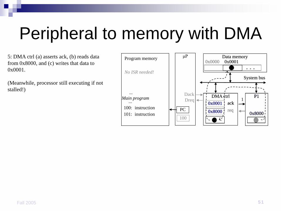
Peripheral to memory with DMA5: DMA ctrl (a) asserts ack, (b) reads data from 0x8000, and (c) writes that data to 0x0001.
(Meanwhile, processor still executing if not stalled!)
ack1

52Fall 2005
Peripheral to memory with DMA6: DMA de-asserts Dreq and ack completing the handshake with P1.
Data memoryμP
DMA ctrl P1
System bus
0x8000101:instruction instruction
...Main program
...
Program memory
PC
100
DreqDack
0x0000 0x0001
100:
No ISR needed!
0x0001
0x8000
ackreqack
0Dreq0

53Fall 2005
Arbitration: Priority arbiter Determine which of multiple peripherals gets service first
from single resource (e.g., microprocessor, DMA) Daisy chain Network oriented
Priority arbiter Single-purpose processor Peripherals communicate with arbiter
Micro-processor
Priority arbiter
Peripheral1
System bus
Int3
57
IntaPeripheral2
Ireq1
Iack2
Iack1Ireq2
2 2
6
54Fall 2005
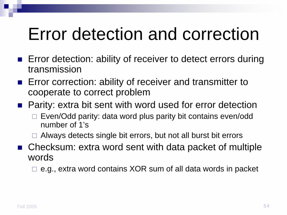
Error detection and correction Error detection: ability of receiver to detect errors during
transmission Error correction: ability of receiver and transmitter to
cooperate to correct problem Parity: extra bit sent with word used for error detection
Even/Odd parity: data word plus parity bit contains even/odd number of 1’s
Always detects single bit errors, but not all burst bit errors Checksum: extra word sent with data packet of multiple
words e.g., extra word contains XOR sum of all data words in packet

55
Communication Protocols
56Fall 2005
Communication Protocols
Layering Lower levels provide services to higher level Easier to design Physical layer
Lowest level in hierarchy Medium to carry data from one actor (device or node) to another
Protocols Serial Parallel Wireless

57Fall 2005
Serial communication Single data wire – transmit one bit at a time Higher data throughput with long distances
Less average capacitance, so more bits per unit of time
Complex protocol and interfacing logic Sender needs to decompose word into bits Receiver needs to recompose bits into word Control signals often on the same wire -> increasing
protocol complexity

58Fall 2005
Serial protocol: 8251 UART Universal asynchronous receiver transmitter Takes parallel data and transmits serially 8251 functions are integrated into standard
PC interface chip.
CPU 8251
status(8 bit)
data(8 bit)
serialport
xmit/rcv

59Fall 2005
Serial communication
time
bit 0 bit 1 bit n-1
nochar
start stop...
Parameters:Baud (bit) rate.Number of bits per character.Parity/no parity.Even/odd parity.Length of stop bit (1, 1.5, 2 bits).

60Fall 2005
Serial protocols: I2C I2C (Inter-IC)
Two-wire serial bus protocol developed by Philips Semiconductors nearly 20 years ago
Enables peripheral ICs to communicate using simple communication hardware appropriate for peripherals where simplicity and low
manufacturing cost are more important than speed
Data transfer rates up to 100 kbits/s and 7-bit addressing possible in normal mode
3.4 Mbits/s and 10-bit addressing in fast-mode Common devices capable of interfacing to I2C bus:
EPROMS, Flash, and some RAM memory, real-time clocks, watchdog timers, and microcontrollers

61Fall 2005
Serial protocols: FireWire FireWire (a.k.a. I-Link, Lynx, IEEE 1394)
High-performance serial bus developed by Apple Computer Inc. Designed for interfacing independent electronic components Data transfer rates from 12.5 to 400 Mbits/s, 64-bit addressing Plug-and-play capabilities Packet-based layered design structure Applications using FireWire include:
disk drives, printers, scanners, cameras Capable of supporting a LAN similar to Ethernet
64-bit address: 10 bits for network ids, 1023 subnetworks 6 bits for node ids, each subnetwork can have 63 nodes 48 bits for memory address, each node can have 281 terabytes of
distinct locations

62Fall 2005
Serial protocols: USB USB (Universal Serial Bus)
Easier connection between PC and peripherals USB 1.1 has 2 data rates:
12 Mbps for increased bandwidth devices 1.5 Mbps for lower-speed devices (joysticks, game pads)
USB 2.0 runs at 480 Mbps; proposals for USB 3.0 up to 3 Gbps Tiered star topology can be used
One USB device (hub) connected to PC Up to 127 USB devices can be connected to hub
USB host controller Manages and controls bandwidth and driver software required by
each peripheral Dynamically allocates power downstream according to devices
connected/disconnected

63Fall 2005
Parallel communication Multiple data, control, and power wires
One bit per wire High data throughput with short distances Typically used when connecting devices on
same IC or same circuit board Bus must be kept short
long parallel wires result in high capacitance values which requires more time to charge/discharge
Data misalignment between wires increases as length increases
Higher cost, bulky

64
Parallel protocols: PCI Bus
PCI Bus (Peripheral Component Interconnect) High performance bus designed by Intel in the 1990’s Interconnects chips, expansion boards, CPU memory
subsystems Data transfer rates of 127.2 to 508.6 Mbits/s and 32 bit
addressing, extended to 64 bit addressing Synchronous bus architectureMultiplexed data/address lines
PCI express – serial protocol 250 Mb/sec – 1 Gb/sec
65
Parallel protocols: ARM Bus
ARM Bus Designed and used internally by ARM Corporation Interfaces with ARM line of processors Many IC design companies have own bus protocol Data transfer rate is a function of clock speed 32-bit addressing
Real-time Comm. Requirements Real-time behavior Efficient, economical
(e.g. centralized power supply) Appropriate bandwidth and communication delay Robustness Fault toleranceMaintainability Diagnosability Security Safety

Electrical robustness Single-ended vs. differential signals
Voltage at input of Op-Amp positive → '1'; otherwise → '0'
Combined with twisted pairs; Most noise added to both wires.
ground
Local groundLocal ground

Differential signals: Evaluation Advantages:
Subtraction removes most of the noise Changes of voltage levels have no effect Reduced importance of ground wiring Higher speed
Disadvantages: Requires negative voltages Increased number of wires and connectors
Applications: USB, FireWire, ISDN Ethernet (STP/UTP CAT 5/6 cables) differential SCSI High-quality analog audio signals (XLR) © wikipedia

Real-time behavior Carrier-sense multiple-access/collision-detection
(CSMA/CD, Standard Ethernet) No guaranteed response time.
Alternatives:token rings, token bussesCarrier-sense multiple-access/collision-avoidance
(CSMA/CA) WLAN techniques with request preceding transmission Each partner gets an ID (priority). After each bus transfer, all partners
try setting their ID on the bus; partners detecting higher ID disconnect themselves from the bus. Highest priority partner gets guaranteed response time; others only if they are given a chance.
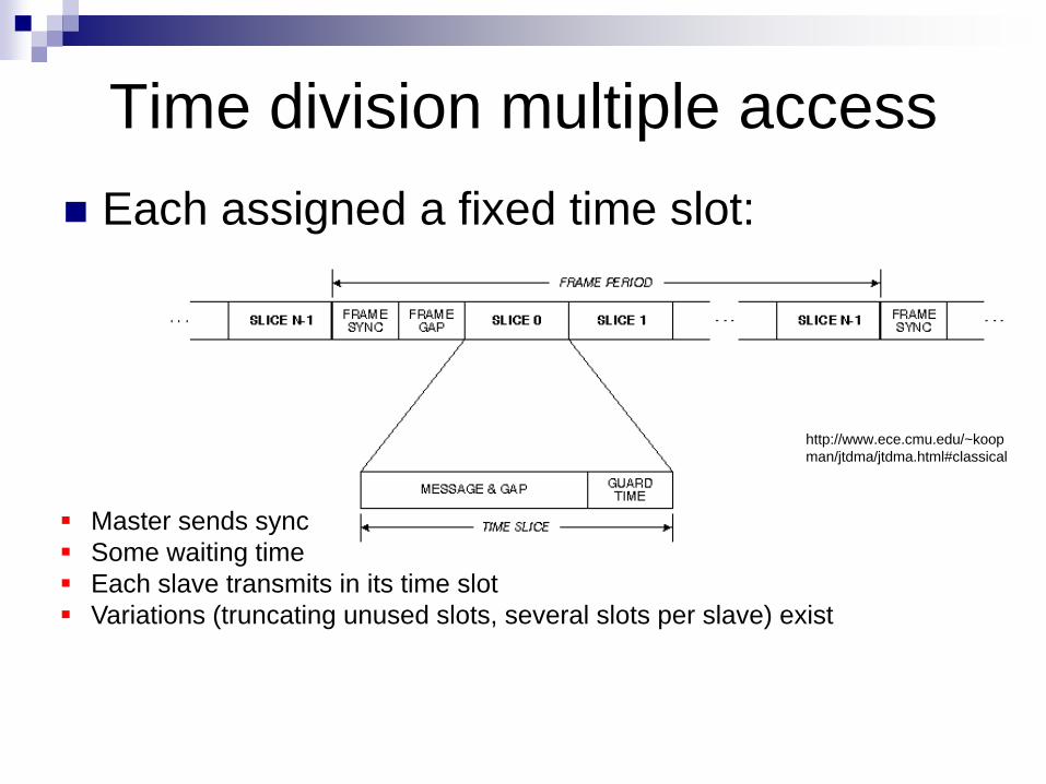
Time division multiple access Each assigned a fixed time slot:
http://www.ece.cmu.edu/~koopman/jtdma/jtdma.html#classical
Master sends sync Some waiting time Each slave transmits in its time slot Variations (truncating unused slots, several slots per slave) exist

Advantages of TDMA-bussesover priority-driven schemes
Provides QoS guarantees in networks on chips TDMA resources support temporal composability, by separating
resource access of different subsystems TDMA resources have a very deterministic timing behavior Can be made fault tolerant Support error detection Support error contention, i.e. a faulty subsystem does not affect the
correct behavior of the remaining system Often applied for single processor scheduling to enable composable
and hierarchical scheduling. Example: ARM AMBA-bus
[Ernesto Wandeler Lothar Thiele: Optimal TDMA Time Slot and Cycle Length Allocation for Hard Real-Time Systems, ASP-DAC, 2006]

Sensor/actuator bussesSensor/actuator busses: Real-time behavior very important; different techniques:
many wires fewer wires expensive & flexible
Field busses: Profibus More powerful/expensive than sensor interfaces;
mostly serial. Emphasis on transmission of small number of bytes.
Examples: Process Field Bus (Profibus) Designed for factory and process automation.Focus on safety; comprehensive protocol mechanisms. 20% market share for field busses.Token passing.≦93.75 kbit/s (1200 m);1500 kbits/s (200m);12 Mbit/s (100m) Integration with Ethernet via Profinet.
[http://www.profibus.com/]
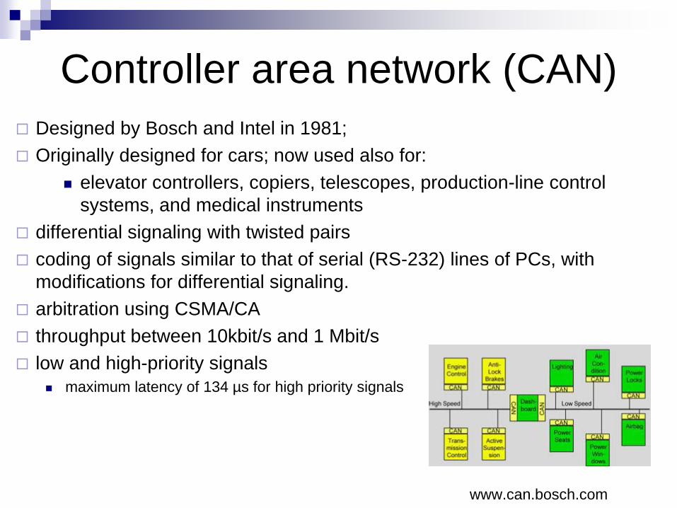
Controller area network (CAN) Designed by Bosch and Intel in 1981; Originally designed for cars; now used also for:
elevator controllers, copiers, telescopes, production-line control systems, and medical instruments
differential signaling with twisted pairs coding of signals similar to that of serial (RS-232) lines of PCs, with
modifications for differential signaling. arbitration using CSMA/CA throughput between 10kbit/s and 1 Mbit/s low and high-priority signals
maximum latency of 134 µs for high priority signals
www.can.bosch.com

Aerospace
Aircraft communication history Until recently, there wasn’t a strong need for networking inside an
aircraft. When digital technologies were introduced, the communication was
limited to digital data link. The introduction of digital technologies happened in the "control
platform" area not in the "information" area.
Source: Thales

Source: Thales
Digital transmission Process Control
sampling and data transmission data : the digital value of an analog parameter (e.g.
speed; height, attitude,....) transmission : no response is expected
Information systems based of information exchange
information : a complex set of abstract values (e.g. digital map, flight plan, list of passenger duty free purchase, failure log book....)
exchange : a response is generally expected, at least to indicated that the information is received.
This "complex set of abstract values" give many bytes of data. This is one reason that calls for higher speed data link
Process control requirements Process control data requires the transmission to be done with a
minimum bounded delay. The stability of the flight relies on this transmission Time, integrity and availability are the key drivers.
Aeronautical response : ARINC 429 protocol no common shared resource (limited risk of common failure)
one source, one line, several receivers the transmitter does not need to know who receives data no time synchronization between the transmitter and receiver
common shared time
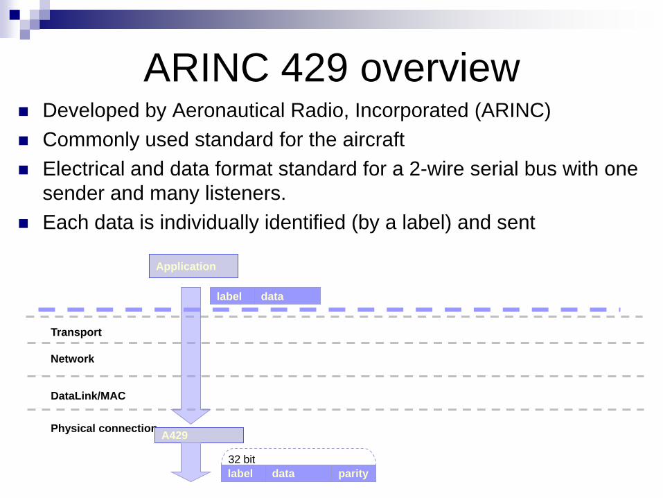
ARINC 429 overview Developed by Aeronautical Radio, Incorporated (ARINC) Commonly used standard for the aircraft Electrical and data format standard for a 2-wire serial bus with one
sender and many listeners. Each data is individually identified (by a label) and sent
Physical connection
DataLink/MAC
Network
Transport
Application
label data
A429
label data parity32 bit

Information system requirements
Ensure that the information is transmitted without any error. Data needs to be acknowledged Messages can be sent again in case of error
Past aircraft uses A429 but added acknowledgement.
Physical connection
DataLink/MAC
Network
Transport
Application
A429 williamsburg
A429
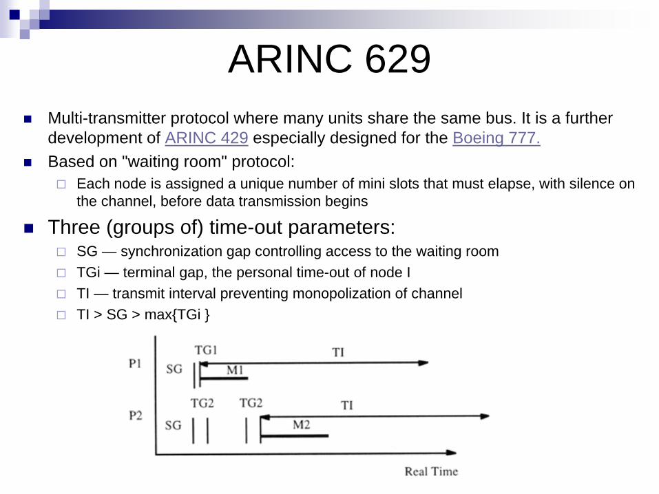
ARINC 629 Multi-transmitter protocol where many units share the same bus. It is a further
development of ARINC 429 especially designed for the Boeing 777. Based on "waiting room" protocol:
Each node is assigned a unique number of mini slots that must elapse, with silence on the channel, before data transmission begins
Three (groups of) time-out parameters: SG — synchronization gap controlling access to the waiting room TGi — terminal gap, the personal time-out of node I TI — transmit interval preventing monopolization of channel TI > SG > max{TGi }
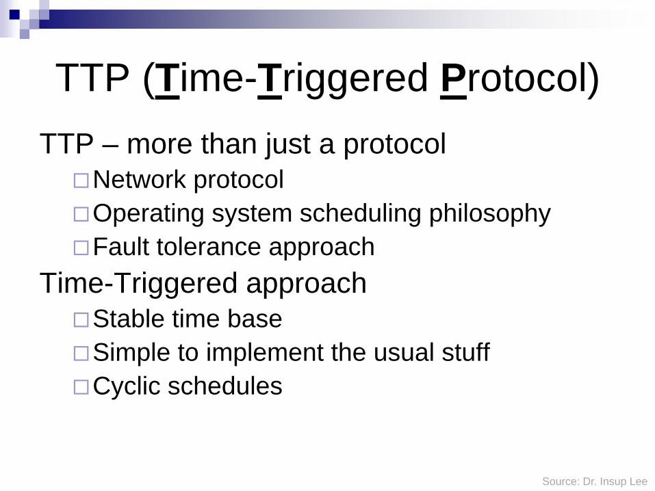
TTP (Time-Triggered Protocol)TTP – more than just a protocolNetwork protocolOperating system scheduling philosophyFault tolerance approach
Time-Triggered approach Stable time baseSimple to implement the usual stuffCyclic schedules
Source: Dr. Insup Lee

TTP versions
TTP/A (Automotive Class A = soft real time)A scaled-down version of TTPA cheaper master/slave variant
Distributed master slave is expensive
TTP/C (Automotive Class C = hard real time)A full version of TTPA fault-tolerant distributed variant

Protocol Layer in TTP/A

Polling OperationMaster polls the other nodes (slaves)Non-master nodes transmit messages
when they are polled Inter-slave communication through the
master
Polling Tradeoffs AdvantageSimple protocol to implementHistorically very popularBounded latency for real-time applications
DisadvantageSingle point of failure from centralized
masterPolling consumes bandwidthNetwork size is fixed during installation(or
master must discover nodes during reconfiguration)

TTP/C TTP/CA time-triggered communication protocol for
safety-critical (fault-tolerant) distributed real-time control systems
Based on a TDMA(Time Division Multiple Access) media access strategy
Based on clock synchronizationFail Silence
A subsystem is fail-silent if it either produces correct results or no results at all, i.e., it is quiet in case it cannot deliver the correct service

Application software in host
FTU Membership
Redundancy Management
SRU Membership
Clock Synchronization
Media Access: TDMA
Host Layer
FTU CNIFault tolerance unit communication network interface
FTU Layer
RM Layer
SRU LayerSmallest replaceable unit
Data Link/Physical Layer
Basic CNI
TTP/C Protocol Layer
FTU Layer Group two or
more nodes into FTUs
RM Layer Provide the
mechanisms for the cold start of a TTP/C cluster
SRU Layer Store the data
fields of the received frames
Data Link/Physical Layer Provide the
means to exchange frames between the nodes

Structure of TTP/C System

(a) Two active nodes, two shadow nodes
(b) Three active nodes with one shadow nodes (Triple modular Redundancy)
(c) Two active nodes without a shadow node
FTU Configuration Examples in TTP/C

Controller to run protocol DPRAM (dual ported RAM)
Used for memory-mapped network interface
BG (Bus Guard) Hardware watchdog to
ensure “fail silent” HW must use highly
accurate time sources Even dual redundant
crystal oscillators as used for Boeing 777

Cycle in TTP/C TDMA Cycle
One FTU sends results twice Then next FTU sends some results And so on, until back to the next message from the first FTU
Cluster Cycle Cluster cycle involves scheduling all messages and tasks
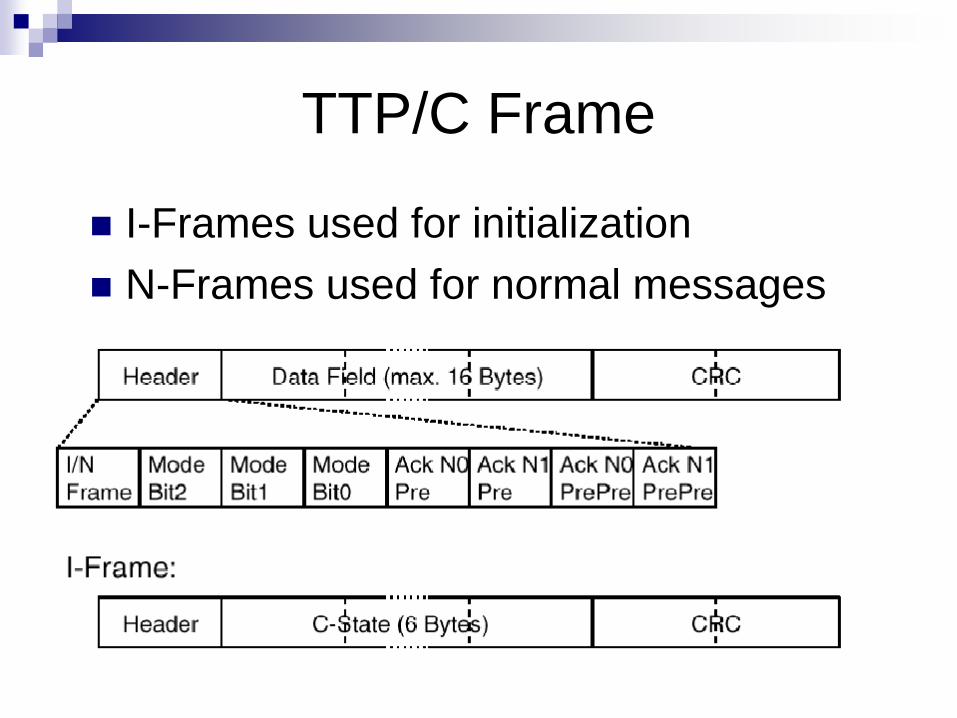
TTP/C Frame
I-Frames used for initialization N-Frames used for normal messages
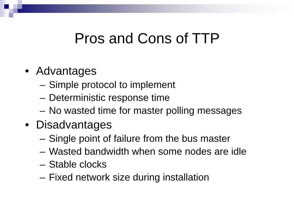
Pros and Cons of TTP
• Advantages– Simple protocol to implement– Deterministic response time– No wasted time for master polling messages
• Disadvantages– Single point of failure from the bus master– Wasted bandwidth when some nodes are idle– Stable clocks– Fixed network size during installation
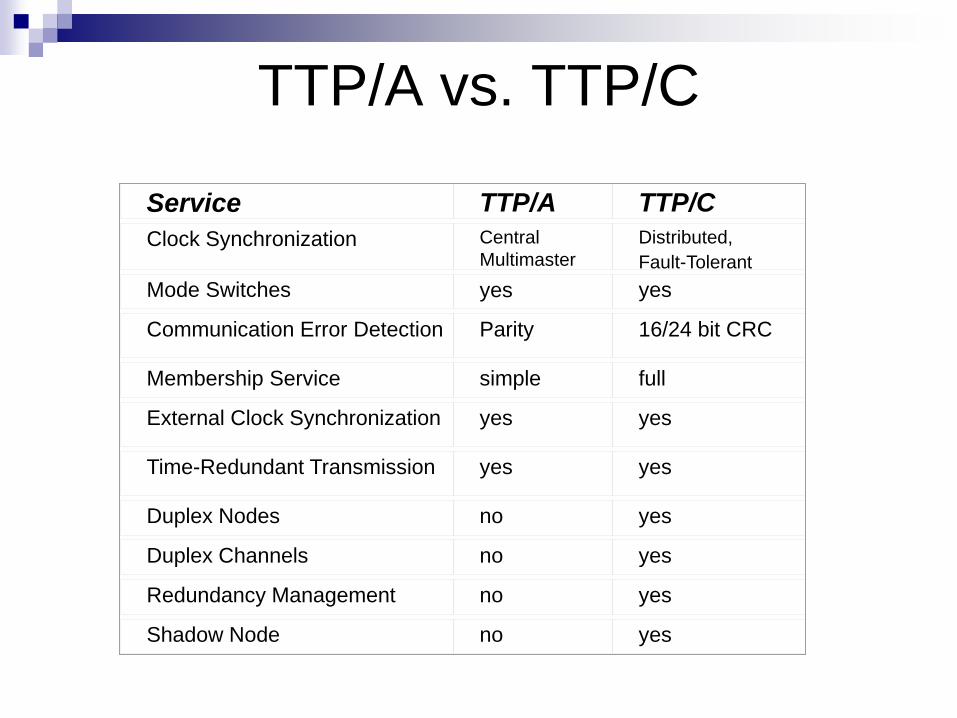
TTP/A vs. TTP/C
Service TTP/A TTP/CClock Synchronization Central
MultimasterDistributed,Fault-Tolerant
Mode Switches yes yes
Communication Error Detection Parity 16/24 bit CRC
Membership Service simple full
External Clock Synchronization yes yes
Time-Redundant Transmission yes yes
Duplex Nodes no yes
Duplex Channels no yes
Redundancy Management no yes
Shadow Node no yes

FlexRay Developed by consortium: BMW, Ford, Bosch,Daimler-
Chrysler, etc.; Specified in SDL Combination TTP and the Byteflight’03 protocols.
Improved error tolerance and time-determinism Meets requirements with transfer rates >> CAN std.
High data rate can be achieved: initially targeted for ~ 10Mbit/sec; design allows much higher data rates
TDMA (Time Division Multiple Access) protocol:Fixed time slot with exclusive access to the bus
Cycle subdivided into a static and a dynamic segment.

TDMA in FlexRay Exclusive bus access enabled for short time in each case.
Dynamic segment for transmission of variable length information.Fixed priorities in dynamic segment: Minislots for each potential sender.Bandwidth used only when it is actually needed.
http
://w
ww.
tzm
.de/
Flex
Ray
/Fle
xRay
_Int
rodu
ctio
n.ht
ml

Time intervals in Flexray
© P
rof.
Form
, TU
Bra
unsc
hwei
g, 2
007
Microtick (µt) = Clock period in partners, may differ between partners Macrotick (mt) = Basic unit of time, synchronized between partners
(=ri×µt, ri varies between partners i) Slot=Interval allocated per sender in static segment (=p×mt, p: fixed (configurable)) Minislot = Interval allocated per sender in dynamic segment (=q×mt, q: variable)
Short minislot if no transmission needed; starts after previous minislot. Cycle = Static segment + dynamic segment + network idle time

Structure of Flexray networks Bus guardian protects the system against failing
processors, e.g. so-called “babbling idiots”
http
://w
ww
.ixxa
t.de/
inde
x.ph
p?se
ite=i
ntro
duct
ion_
flexr
ay_e
n&ro
ot=5
873&
syst
em_i
d=58
75&c
om=f
orm
ular
_suc
he_t
reffe
r&m
arki
erun
g=fle
xray

Other field busses LIN: low cost bus for interfacing sensors/actuators in
the automotive domain MOST: Multimedia bus for the automotive domain MAP: designed for car factories. EIB: designed for smart buildings.
CSMA/CA; low data rate.
IEEE 488: Designed for laboratory equipment. Attempts to use standard Ethernet. However, timing
predictability remains a serious issue.

Event vs. time triggered Event Triggered (ET):
Computation/communication triggered by an external event Events are generated by (primarily) state changes in the environment Efficient — only do things when they need to be done; rest and save
energy/cpu time/bandwidth/. . . Otherwise High peak-load if multiple events happen at once Hard to analyze due to asynchronous nature of events
Time Triggered (TT): Computation/communication triggered by progress of a system clock Events happen according to a fixed schedule Inefficient — do things
periodically, whether needed or not Enhanced analizability due to easily characterizable load, predictable
interaction sequences, bus use, etc.
100
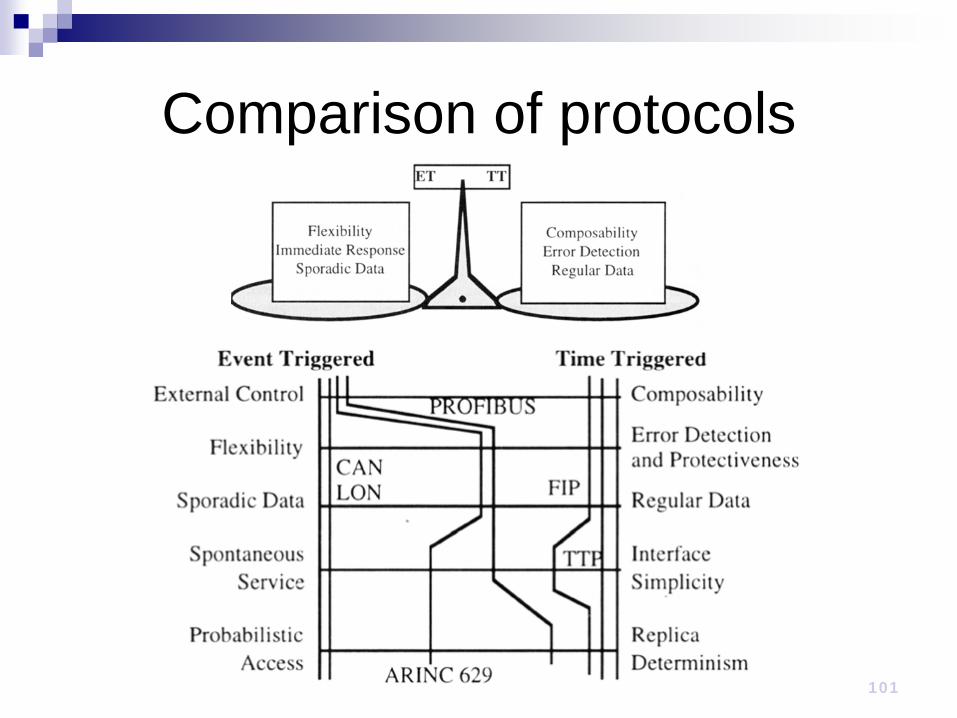
Comparison of protocols
101

102
Wireless communication Infrared (IR)
Frequencies just below visible light spectrum Diode emits infrared light to generate signal Infrared transistor detects signal Cheap to build but need line of sight, limited range Data transfer rate of 9.6 kbps and 4 Mbps
Radio frequency (RF) Electromagnetic wave frequencies in radio spectrum Analog circuitry and antenna needed on both sides Line of sight not needed, transmitter power
determines range

Bluetooth, Wibree, ZigbeeB
luet
ooth • IEEE
802.15.1• Developed
and licensed by the Bluetooth Special Interest Group (SIG)
Wib
ree • Being
adopted into Bluetooth specification
• New name: Bluetooth Low Energy Technology
ZigB
ee • IEEE 802.15.4
• Maintained and published by the ZigBeeAlliance

Side By SideBluetooth Wibree ZigBee
Band 2.4GHz 2.4GHz 2.4GHz, 868MHz, 915MHz
Antenna/HW Shared Independent
Power 100 mW ~10 mW 30 mW
Target Battery Life
Days – months 1-2 years 6 months – 2 years
Range 10-30 m 10 m 10-75 m
Data Rate 1-3 Mbps 1 Mbps 25-250 Kbps
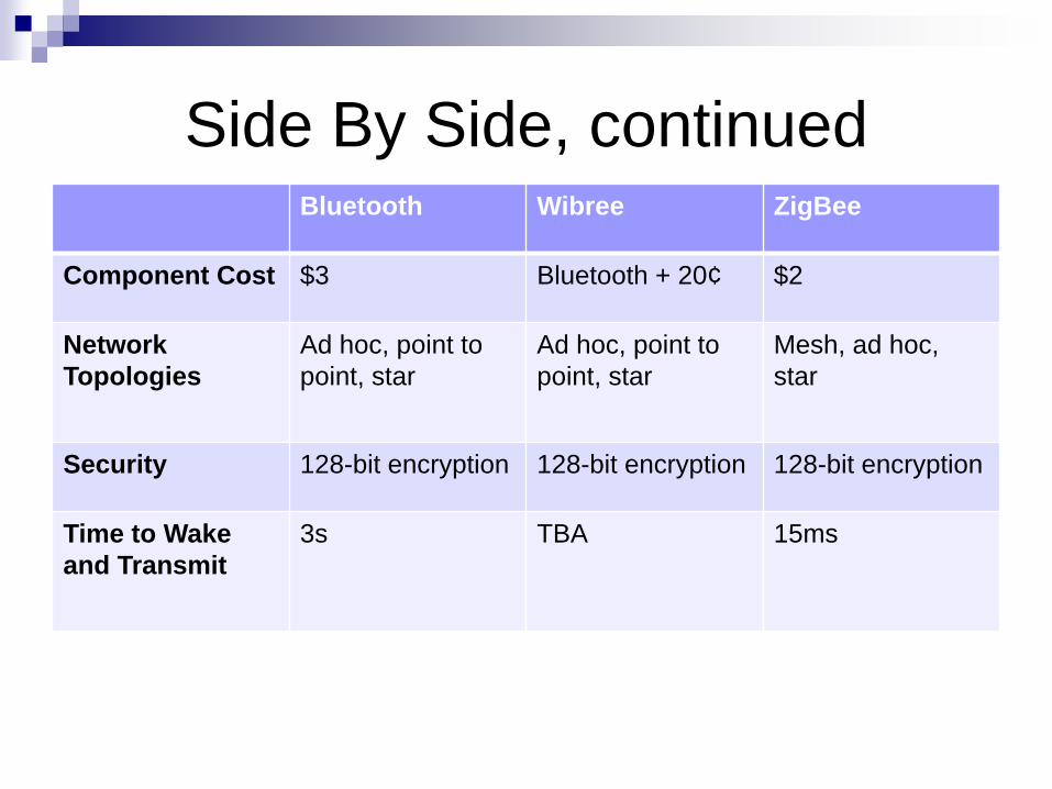
Side By Side, continuedBluetooth Wibree ZigBee
Component Cost $3 Bluetooth + 20¢ $2
Network Topologies
Ad hoc, point to point, star
Ad hoc, point to point, star
Mesh, ad hoc, star
Security 128-bit encryption 128-bit encryption 128-bit encryption
Time to Wake and Transmit
3s TBA 15ms

106
Wireless Protocols: 802.11 IEEE 802.11
Standard for wireless LANs Specifies parameters for PHY and MAC layers of
network PHY layer
handles transmission of data between nodes data transfer rates up to 54Mbps (108 Mbps in 802.11a) operates in 2.4 / 5 GHz frequency band (RF)
MAC layer medium access control layer protocol responsible for maintaining order in shared medium collision avoidance/detection
107
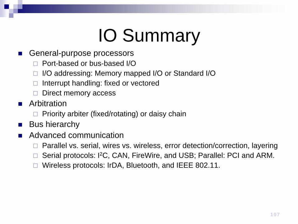
IO Summary General-purpose processors
Port-based or bus-based I/O I/O addressing: Memory mapped I/O or Standard I/O Interrupt handling: fixed or vectored Direct memory access
Arbitration Priority arbiter (fixed/rotating) or daisy chain
Bus hierarchy Advanced communication
Parallel vs. serial, wires vs. wireless, error detection/correction, layering Serial protocols: I2C, CAN, FireWire, and USB; Parallel: PCI and ARM. Wireless protocols: IrDA, Bluetooth, and IEEE 802.11.