Embed Size (px)
Citation preview
1
CSC and Overlap Track Finder
• System Re-Design– Rescoped to 3 stations
– 60 degree CSC sectors– Data flow
– Crate Arrangement
• Cost and Schedule
Darin Acosta
University of Florida
(J.Hauser, UCLA & P.Padley, Rice)
TriDAS Progress ReportApril 28, 1998

DoE/NSF Review, April, 1998
CSC Trigger Block Diagram
Wire cards(3-7/chamber)
ME1/1Motherboard
96-channelboards
Twisted flat cablesto Motherboardsand Port Cards
Counts (3 stns):
2016 Strip Cards
1800 Wire Cards
432 Motherboards
48 Port Cards
336 Data Links
8 Track Finder Crates
ME1/2
ME3/1
60O
CSC and OverlapTrackFinder
Global Muon
Trigger
GlobalLevel 1Trigger
≤2Muontracks
Detector
ME3/2
ME4/1
ME4/2
≤4Muontracks
96-channelboards
Strip cards (4-5/chamber) GHz optical links
to Track Finder Crates
StripRoads
WireRoads
ME1PortCard
ME1/3
≤3 MuonStubs
≤2 MuonStubs
ME3PortCard
ME4PortCard
ME2/1
ME2/2
ME2PortCard
Trigger Room
DoE/NSF Review, April, 1998
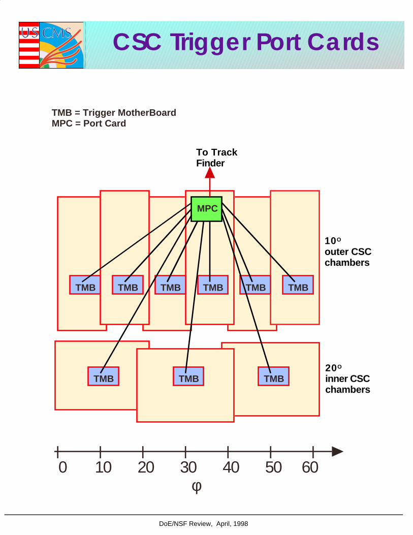
CSC Trigger Port Cards
φ0 10 20 30 40 50 60
TMB TMBTMB
TMB TMB TMB TMB TMB TMB
To TrackFinder
TMB = Trigger MotherBoardMPC = Port Card
10O
outer CSCchambers
20O
inner CSCchambers
MPC

DoE/NSF Review, April, 1998
15o
75o
135o
195o
255o
315o


DoE/NSF Review, April, 1998
CSC & Overlap TF Block Diagram
Glossary and Part CountTMB: Trigger Motherboards (432 or 540)MPC: Muon Port Cards (48 or 60)SR: Sector Receivers for CSC (24)SR-DT: Sector Receivers for DT (12 or 24)SP-CSC: Sector Processors for CSC region (12)SP-Over: Sector Processors for Overlap region (12)OI, CI, CO, BP: Optical in, copper in, copper out, backplane

DoE/NSF Review, April, 1998
Specific Functions of Sector Receiver
Block diagram

LCT content (from each MPC to SRC)
Signal Bits
Half-Strip ID 5
Strip Left/Right Bend Angle 1
Strip Hi/Lo Pt Flag 1
Strip Pattern ID 8
Strip FEB Number 3
Strip Status 1
Wire Gang ID 4
Wire Pattern ID 7
Wire Status 1
Wire FEB Number 3
Wire BXN 8
Chamber ID 4
Total 46
Table 6
Data to be send from each SRC to SP
Data Bits
Phi position 12
Rapidity 11
Local bend angle 6
Quality 3
Total 32
1 of 1 5/4/98 2:21 PM
CMS Endcap Muon Trigger Motherboard Specification file:///C|/Acosta/bits.html

Jay Hauser, UCLA 1998
Sector Receiver Layout
Connectors, buffers
Optical links
BackPlane
Inputs/Outputs:Transceivers and Glinks - 216 bits/xing requires 14 linksCopper: CSC to Overlap crate cables require 8 x 60-pinBackplane: 3 192-pin Z-pack connectors
Processing:Buffers for copper signalsFPGAs and Memory look-ups for main functionality:
space and time alignment2D to 3D stub conversionoutput formatting
plus configuration EPROMs and FIFOs for data storage
9U
FPGA
FPGA
FPGA
FPGA
FPGA RAM FIFO

3
Preliminary Estimate of SR Latency
Input serial to parallel conversion and synchronization: 3
LUT conversion and alignment: 3 - 4
Output reformatting and buffering: 2 - 3
------
8 - 10 b.x.

Jay Hauser, UCLA 1998
Sector Processor Layout
Front panel output data
Backplaneinput data
Inputs/Outputs:Backplane inputs: 3 192-pin Z-pack connectorsFront panel outputs to Global mu: three 60-pin cables
Processing:FPGAs and Memory look-ups for main functionality:
muon stub coincidencep
T lookup
output formattingConfiguration EPROMs and FIFOs for data storageBuffers for data to global muon trigger
9U
FPGA
RAM
FIFO
FPGA
FPGA
FPGA
FPGA
FPGA
FPGA
FPGA
FPGA
FPGA
DAQ storage

DoE/NSF Review, April, 1998
Muon Track Finder Crates and Data Flow
180 degrees in φ per crate
Drift Tubes organized by wheel
CSC and Overlap regions are extra "wheels"
CSC signals received in CSC-only racks
CSC and DT signals fanned out to Overlap racks• Endcap crates do not share data at φ boundaries
• bending is smaller in endcap region
• chamber coverage is "seamless"
• CSC-only racks send ME1,2,3 info. to overlap racks Data flow between crates:
CSConly
φ
Wheel-4 -3 -2 -1 0 1 2 3 4
0
180
360
DT only
CSConly
Overlap
Overlap
Jay Hauser, UCLA March, 1998
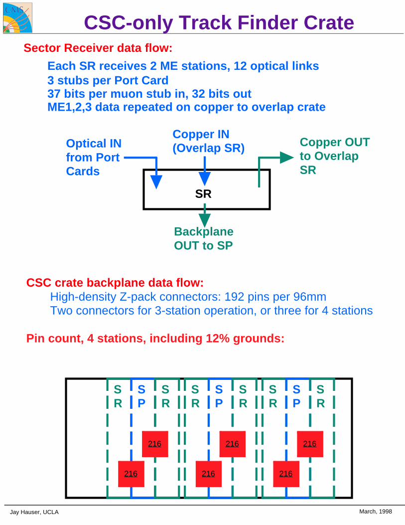
CSC-only Track Finder CrateSector Receiver data flow:
Each SR receives 2 ME stations, 12 optical links3 stubs per Port Card37 bits per muon stub in, 32 bits outME1,2,3 data repeated on copper to overlap crate
CSC crate backplane data flow:High-density Z-pack connectors: 192 pins per 96mmTwo connectors for 3-station operation, or three for 4 stations
Pin count, 4 stations, including 12% grounds:
SR
SR
SR
SP
SP
SP
216
SR
SR
SR
216 216 216
216 216
Optical INfrom PortCards
Copper IN(Overlap SR) Copper OUT
to OverlapSR
Backplane OUT to SP
SR

Jay Hauser, UCLA March, 1998
Overlap Track Finder Crate
• CSC crate backplane data flow:• High-density Z-pack connectors: 192 pins per 96mm• Three connectors required• Small amount of backplane space left for readout bus• Consider using front panel connections
SRCSC
SP
216
SRDT
222
SRCSC
108
SRCSC
SP
216
SRDT
222
SRCSC
108
SRCSC
SP
216
SRDT
222
SRCSC
108
• Two CSC and one DT Sector Receivers per SP-OVER• DT signals repeated on copper from Wheel +-2?
• 32 bits/stub for CSC, 22 bits/stub for DT
• Assume 3 stubs/sector/station for CSC and DT

Jay Hauser, UCLA March, 1998
Track Finder Data I/O Counts
CSC/Overlap Sector Receivers: 636222 optical inputs, 222 copper in/out, 192 backplane output
CSC Sector Processors: 422384 backplane inputs, 38 front-panel outputs
Overlap Sector Processors: 524486 backplane inputs, 38 front-panel outputs
Barrel Sector Processors: 1670/2474(6/9-neighbor versions)
Main savings: ignore φ overlaps

3/21/98 D. Acosta -- UF Endcap Muon Meeting 8
Design Considerations
• Tracks crossing sector boundaries are not linked bysector processors– reduces data flow on VME backplane
– PT>10 ⇒ ∆φ12 < 2°
• Magnetic field is non-uniform in endcap– Extrapolation in φ is more complicated– PT assignment depends on η ⇒ LUT complication
• 2D or 3D track finding?– Track finding in η-r to reduce combinatorics?
• Ghost suppression– Try all η, φ possibilities from chamber, or take best
matches from MPC?
• Overlap region– Problem with ambiguity in η
• What is sector occupancy from background?


3/21/98 D. Acosta -- UF Endcap Muon Meeting 9
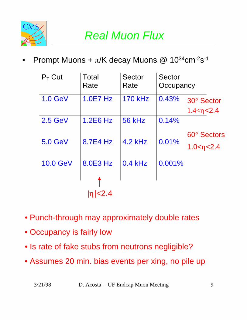
Real Muon Flux
• Prompt Muons + π/K decay Muons @ 1034cm-2s-1
PT Cut TotalRate
SectorRate
SectorOccupancy
1.0 GeV 1.0E7 Hz 170 kHz 0.43%
2.5 GeV 1.2E6 Hz 56 kHz 0.14%
5.0 GeV 8.7E4 Hz 4.2 kHz 0.01%
10.0 GeV 8.0E3 Hz 0.4 kHz 0.001%
30° Sector
60° Sectors
|η|<2.4
1.4<η<2.4
1.0<η<2.4
• Punch-through may approximately double rates
• Occupancy is fairly low
• Is rate of fake stubs from neutrons negligible?
• Assumes 20 min. bias events per xing, no pile up
3/21/98 D. Acosta -- UF Endcap Muon Meeting 10
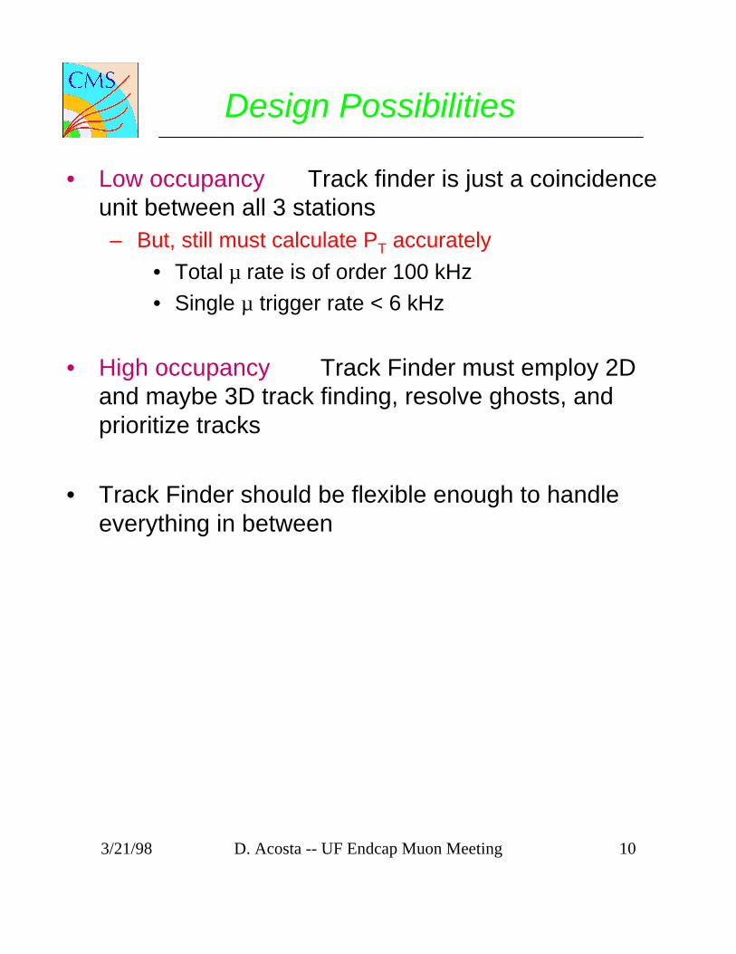
Design Possibilities
• Low occupancy ⇒ Track finder is just a coincidenceunit between all 3 stations– But, still must calculate PT accurately
• Total µ rate is of order 100 kHz• Single µ trigger rate < 6 kHz
• High occupancy ⇒ Track Finder must employ 2Dand maybe 3D track finding, resolve ghosts, andprioritize tracks
• Track Finder should be flexible enough to handleeverything in between

WBS Task Name3.1.1 CSC Muon Trigger
3.1.1.1 Muon Port Cards (MPC)
3.1.1.2 Sector Receivers (SR)
3.1.1.2.1 SR Design
3.1.1.2.1. 1 SR Initial System Design
3.1.1.2.1. 2 SR Initial Proto. Design
3.1.1.2.1. 3 SR Proto. Design
3.1.1.2.2 SR Proto. Construction
3.1.1.2.3 SR Proto. Test
3.1.1.2.4 SR ASIC and Board Design
3.1.1.2.5 SR Active Components
3.1.1.2.6 SR Boards
3.1.1.2.7 SR Installation
3.1.1.2.8 SR Spares
3.1.1.3 CSC Sector Processors (SP-CSC)
3.1.1.3.1 SP-CSC Design
3.1.1.3.1. 1 SP-CSC Initial System Des i
3.1.1.3.1. 2 SP-CSC Proto. Design
3.1.1.3.2 SP-CSC Proto. Construction
3.1.1.3.3 SP-CSC Proto. Test
3.1.1.3.4 SP-CSC ASIC and Board Design
3.1.1.3.5 SP-CSC Active Components
3.1.1.3.6 SP-CSC Boards
3.1.1.3.7 SP-CSC Installation
3.1.1.3.8 SP-CSC Spares
3.1.1.4 Overlap Sector Processors (SP-OVR)
3.1.1.4.1 SP-OVR Design
3.1.1.4.1. 1 SP-OVR Initial System Des i
3.1.1.4.1. 2 SP-OVR Proto. Design
3.1.1.4.2 SP-OVR Proto. Construction
3.1.1.4.3 SP-OVR Proto. Test
3.1.1.4.4 SP-OVR ASIC and Board Design
3.1.1.4.5 SP-OVR Active Components
3.1.1.4.6 SP-OVR Boards
Apr
Oct 7
May 13
Mar 4
ar 5 Sep 30
Oct 1 May 13
May 14 Sep 30
Oct 1 Apr 21
Apr 24 Sep 7
Mar 12 Jul 29
Sep 10 May 20
May 21 Oct 7
Mar 12 Jul 29
r 5 Ap
r 5 May 13
ar 5 May 13
ay 14 May 13
May 14 Sep 30
Oct 1 Jul 21
Jul 24 Jul 22
Jan 22 Jun 10
Jul 23 Nov 2
Nov 26 Apr
Jan 22 Jun 10
y 14 Feb
y 14 Jul 22
ay 14 Jul 22
Jul 23 Jul 22
Jul 23 Dec 9
Dec 10 May 12
May 15 May 13
Oct 29 Apr 1
May 14 Sep 16
Jul Jan Jul Jan Jul Jan Jul Jan Jul Jan Jul Jan Jul Jan Jul
97 1998 1999 2000 2001 2002 2003 2004
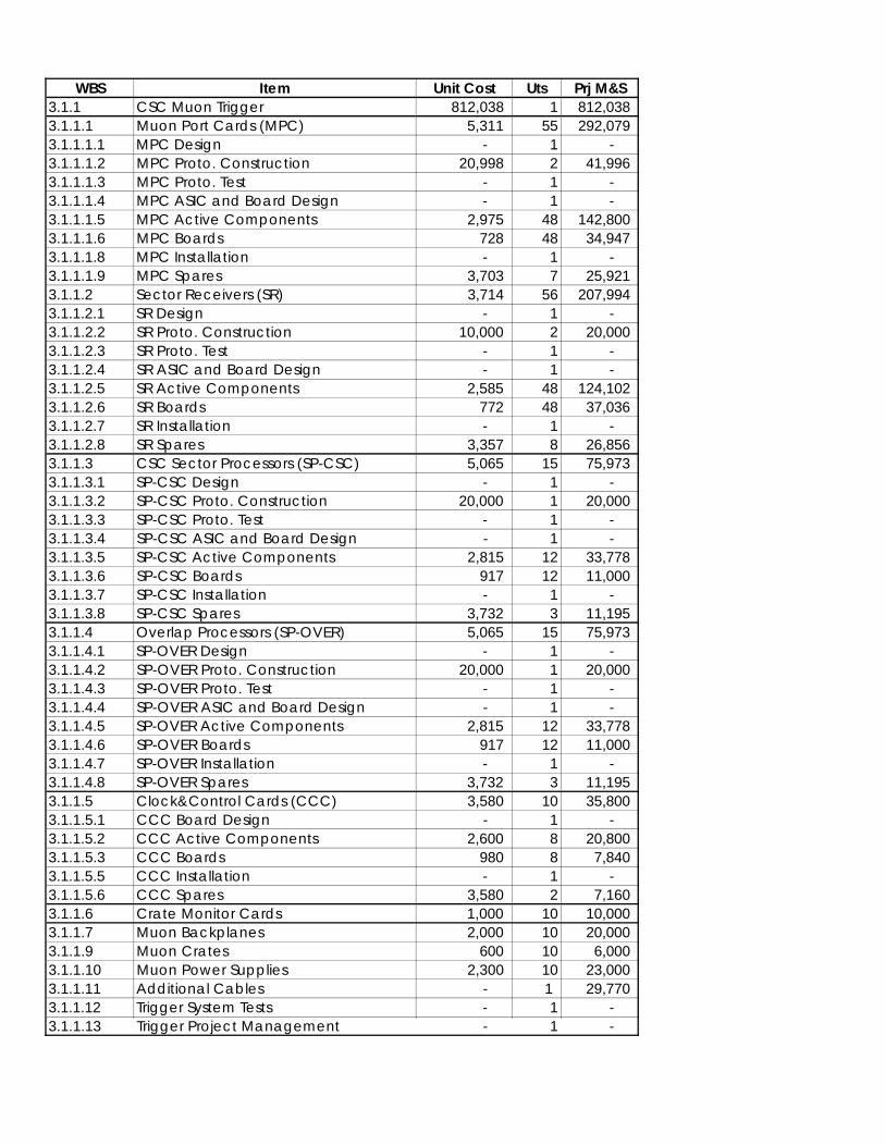
WBS Item Unit Cost Uts Prj M&S3.1.1 CSC Muon Trigger 812,038 1 812,038 3.1.1.1 Muon Port Cards (MPC) 5,311 55 292,079 3.1.1.1.1 MPC Design - 1 - 3.1.1.1.2 MPC Proto. Construction 20,998 2 41,996 3.1.1.1.3 MPC Proto. Test - 1 - 3.1.1.1.4 MPC ASIC and Board Design - 1 - 3.1.1.1.5 MPC Active Components 2,975 48 142,800 3.1.1.1.6 MPC Boards 728 48 34,947 3.1.1.1.8 MPC Installation - 1 - 3.1.1.1.9 MPC Spares 3,703 7 25,921 3.1.1.2 Sector Receivers (SR) 3,714 56 207,994 3.1.1.2.1 SR Design - 1 - 3.1.1.2.2 SR Proto. Construction 10,000 2 20,000 3.1.1.2.3 SR Proto. Test - 1 - 3.1.1.2.4 SR ASIC and Board Design - 1 - 3.1.1.2.5 SR Active Components 2,585 48 124,102 3.1.1.2.6 SR Boards 772 48 37,036 3.1.1.2.7 SR Installation - 1 - 3.1.1.2.8 SR Spares 3,357 8 26,856 3.1.1.3 CSC Sector Processors (SP-CSC) 5,065 15 75,973 3.1.1.3.1 SP-CSC Design - 1 - 3.1.1.3.2 SP-CSC Proto. Construction 20,000 1 20,000 3.1.1.3.3 SP-CSC Proto. Test - 1 - 3.1.1.3.4 SP-CSC ASIC and Board Design - 1 - 3.1.1.3.5 SP-CSC Active Components 2,815 12 33,778 3.1.1.3.6 SP-CSC Boards 917 12 11,000 3.1.1.3.7 SP-CSC Installation - 1 - 3.1.1.3.8 SP-CSC Spares 3,732 3 11,195 3.1.1.4 Overlap Processors (SP-OVER) 5,065 15 75,973 3.1.1.4.1 SP-OVER Design - 1 - 3.1.1.4.2 SP-OVER Proto. Construction 20,000 1 20,000 3.1.1.4.3 SP-OVER Proto. Test - 1 - 3.1.1.4.4 SP-OVER ASIC and Board Design - 1 - 3.1.1.4.5 SP-OVER Active Components 2,815 12 33,778 3.1.1.4.6 SP-OVER Boards 917 12 11,000 3.1.1.4.7 SP-OVER Installation - 1 - 3.1.1.4.8 SP-OVER Spares 3,732 3 11,195 3.1.1.5 Clock&Control Cards (CCC) 3,580 10 35,800 3.1.1.5.1 CCC Board Design - 1 - 3.1.1.5.2 CCC Active Components 2,600 8 20,800 3.1.1.5.3 CCC Boards 980 8 7,840 3.1.1.5.5 CCC Installation - 1 - 3.1.1.5.6 CCC Spares 3,580 2 7,160 3.1.1.6 Crate Monitor Cards 1,000 10 10,000 3.1.1.7 Muon Backplanes 2,000 10 20,000 3.1.1.9 Muon Crates 600 10 6,000 3.1.1.10 Muon Power Supplies 2,300 10 23,000 3.1.1.11 Additional Cables - 1 29,770 3.1.1.12 Trigger System Tests - 1 - 3.1.1.13 Trigger Project Management - 1 -
2
Conclusions
• Major Changes:
– Arrangement of data into 60° sectors withboundaries at 15°, 75°, 135°, …
– Ignore φ boundaries• Negligible PT - dependent loss
• Potential 10°/60° = 17% loss in overlapregion
• Cost savings (~20%) from reduced numberof crates and boards
• Initial system design phase• Details can be found here:
http://www-collider.physics.ucla.edu/cms/trigger/
http://bonner-ntserver.rice.edu/motherboard/Archive/src.htm