Embed Size (px)
Citation preview
CS4617 Computer ArchitectureLecture 20: Pipelining
Reference: Appendix C, Hennessy & PattersonReference: Hamacher et al.
Dr J Vaughan
November 2013
1/39

5-stage pipeline
Clock cycle
Instr No 1 2 3 4 5 6 7 8 9
i IF ID EX MEM WB
i+1 IF ID EX MEM WB
i+2 IF ID EX MEM WB
i+3 IF ID EX MEM WB
i+4 IF ID EX MEM WB
Table: Figure C.1: Simple RISC pipeline
2/39

Forwarding
I Forwarding can be generalised to pass a result directly to theFU that requires it
I A result is forwarded from the pipeline register at the outputof one unity to the input of another, rather than from theresult of a unit to the input of the same unit
I ExampleI DADD R1, R2, R3I LD R4, 0(R1)I SD R4, 12(R1)
I To prevent a stall in this sequence, need to forward the valuesof ALU output and memory unit output from the pipelineregisters to the ALU and data memory inputs
I Figure C8 shows all the forwarding paths for this example.
3/39

Forwarding of operand required by stores during MEM
Copyright © 2011, Elsevier Inc. All rights Reserved. 7
Figure C.8 Forwarding of operand required by stores during MEM. The result of the load is forwarded from the memory output to the memory input to be stored. In addition, the ALU output is forwarded to the ALU input for the address calculation of both the load and the store (this is no different than forwarding to another ALU operation). If the store depended on an immediately preceding ALU operation (not shown above), the result would need to be forwarded to prevent a stall.
Copyright c© 2011, Elsevier Inc. All rights reserved
4/39

Data Hazards requiring stalls
I Not all data hazards can be handled by bypassingI Example
I LD R1, 0(R2)I DSUB R4, R1, R5I AND R6, R1, R7I OR R8, R1, R9
I See Figure C9
5/39

A data hazard that cannot be handled by bypassing
Copyright © 2011, Elsevier Inc. All rights Reserved. 8
Figure C.9 The load instruction can bypass its results to the AND and OR instructions, but not to the DSUB, since that would mean forwarding the result in “negative time.”
Copyright c© 2011, Elsevier Inc. All rights reserved
6/39

Data Hazards requiring stalls (continued)I LD does not have the data until the end of clock cycle 4 (its
MEM cycle)I DSUB needs to have the data by the beginning of clock cycle
4 =⇒ the data hazard from the result of a load instructioncannot be completely eliminated with simple hardware
I The result can be forwarded immediately to the ALU for use inthe AND operation that begins 2 clock cycles after the load.
I The OR instruction receives the value through the register fileI DSUB receives the forwarded result 1 clock cycle too lateI Hardware called a pipeline interlock must be added to detect
a hazard and stall the pipeline until it is cleared.I CPI for the stalled instruction increases by the length of the
stall (1 clock cycle in this case)I Figure C10 shows the pipeline before and after the stallI Forwarding to AND goes through the register file because the
stall causes instructions starting with DSUB to move 1 cyclelater
7/39

Data Hazards requiring stalls (continued)
Clock cycle
Instr No 1 2 3 4 5 6 7 8
LD R1, 0(R2) IF ID EX MEM WB
DSUB R4, R1, R5 IF ID EX MEM WB
AND R6, R1, R7 IF ID EX MEM WB
OR R8, R1, R9 IF ID EX MEM WB
Table: Figure C10(a): The MEM cycle of the load produces a value thatis needed in the EX cycle of the DSUB, which occurs at the same time
8/39

Data Hazards requiring stalls (continued)
Clock cycle
Instr No 1 2 3 4 5 6 7 8 9
LD R1, 0(R2) IF ID EX MEM WB
DSUB R4, R1, R5 IF ID stall EX MEM WB
AND R6, R1, R7 IF stall ID EX MEM WB
OR R8, R1, R9 stall IF ID EX MEM WB
Table: Figure C10(b): Resolution of the problem with a stall
9/39

Branch Hazards
I When a branch is executed, it may change PC to PC+4 orsomething different
I If Ii is a taken branch, PC is not normally changed until theend of ID, after completion of address calculation andcomparison
I Figure C11 shows that the simplest way to deal with branchesis to redo instruction fetch after the branch, having detectedthe branch during ID
I The first IF is not useful and amounts to a stall
I If the branch is untaken, repetition of the IF is not necessarysince the correct instruction has been fetched
I One stall cycle for every branch gives a performance loss of10% to 30% so techniques to deal with this are needed
10/39

Branch causing 1-cycle stall
Clock cycle
Instr No 1 2 3 4 5 6 7 8 9
Branchinstruction
IF ID EX MEM WB
Branch suc-cessor
IF IF ID EX MEM WB
Branch suc-cessor + 1
IF ID EX MEM WB
Branch suc-cessor + 2
IF ID EX MEM WB
Table: Figure C11: A branch causes a 1-cycle stall in the 5-stage pipeline
11/39

Reducing Pipeline Branch Penalties
I 4 compile time schemes
I The actions for a branch are static: fixed for each branchduring the entire execution
1. Freeze or flush the pipeline: the simplest schemeI Hold or delete any instructions after the branch until the
branch destination is knownI This is the solution shown in Figure C11I The branch penalty is fixed and cannot be reduced by software
12/39

Reducing Pipeline Branch Penalties
2 Treat every branch as not taken.I Do not change processor state until branch outcome is definitely
knownI Complexity: when might state change? How to reverse a change?I This is known as predicted-not-takenI Continue to fetch instructions as if there were no branchI Restart fetch at target address (and turn previously fetched
instruction into a NOP) if the branch is takenI See Figure C12
13/39

Predicted-not-taken when the branch is untaken
Clock cycle
Instr No 1 2 3 4 5 6 7 8 9
Untakenbranchinstruction
IF ID EX MEM WB
Instructioni+1
IF ID EX MEM WB
Instructioni+2
IF ID EX MEM WB
Instructioni+3
IF ID EX MEM WB
Instructioni+4
IF ID EX MEM WB
Table: Figure C12(a) Predicted-not-taken when the branch is untaken
14/39

Predicted-not-taken when the branch is taken
Clock cycle
Instr No 1 2 3 4 5 6 7 8 9
Untakenbranchinstruction
IF ID EX MEM WB
Instructioni+1
IF idle idle idle idle
Instructioni+2
IF ID EX MEM WB
Instructioni+3
IF ID EX MEM WB
Instructioni+4
IF ID EX MEM WB
Table: Figure C12(b) Predicted-not-taken when the branch is taken
15/39
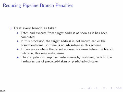
Reducing Pipeline Branch Penalties
3 Treat every branch as takenI Fetch and execute from target address as soon as it has been
computedI In this processor, the target address is not known earlier the
branch outcome, so there is no advantage in this schemeI In processors where the target address is known before the branch
outcome, this may make senseI The compiler can improve performance by matching code to the
hardwares use of predicted-taken or predicted-not-taken
16/39

Reducing Pipeline Branch Penalties
4 Delayed branchI Execution cycle with a branch delay of 1I Branch instruction
Sequential successor 1Branch target if taken
I The sequential successor is in the branch delay slotThis is executed in either case
I Most processors have a 1-instruction branch delayI See Figure C13
17/39

Delayed branch when branch is untaken
Clock cycle
Instr No 1 2 3 4 5 6 7 8 9
Untakenbranchinstruction
IF ID EX MEM WB
Branch delayinstruction(i+1)
IF ID EX MEM WB
Instructioni+2
IF ID EX MEM WB
Instructioni+3
IF ID EX MEM WB
Instructioni+4
IF ID EX MEM WB
Table: Figure C13(a) Behaviour of a delayed branch if branch is untaken
18/39

Delayed branch when branch is untaken
Clock cycle
Instr No 1 2 3 4 5 6 7 8 9
Untakenbranchinstruction
IF ID EX MEM WB
Branch delayinstruction(i+1)
IF ID EX MEM WB
Branch tar-get
IF ID EX MEM WB
Branch tar-get + 1
IF ID EX MEM WB
Branch tar-get + 2
IF ID EX MEM WB
Table: Figure C13(b) Delayed branch behaviour is the same if branch istaken
19/39

Delayed branch (continued)
I Note that another branch should not be put in the delay slot
I The compiler inserts useful instructions in the delay slot
I See Figure C14 for optimisations
20/39

Forwarding of operand required by stores during MEM
Copyright © 2011, Elsevier Inc. All rights Reserved. 9
Figure C.14 Scheduling the branch delay slot. The top box in each pair shows the code before scheduling; the bottom box shows the scheduled code. In (a), the delay slot is scheduled with an independent instruction from before the branch. This is the best choice. Strategies (b) and (c) are used when (a) is not possible. In the code sequences for (b) and (c), the use of R1 in the branch condition prevents the DADD instruction (whose destination is R1) from being moved after the branch. In (b), the branch delay slot is scheduled from the target of the branch; usually the target instruction will need to be copied because it can be reached by another path. Strategy (b) is preferred when the branch is taken with high probability, such as a loop branch. Finally, the branch may be scheduled from the not-taken fall-through as in (c). To make this optimization legal for (b) or (c), it must be OK to execute the moved instruction when the branch goes in the unexpected direction. By OK we mean that the work is wasted, but the program will still execute correctly. This is the case, for example, in (c) if R7 were an unused temporary register when the branch goes in the unexpected direction.
Copyright c© 2011, Elsevier Inc. All rights reserved
21/39

Limitations on delayed-branch scheduling
1. Restrictions on instructions that may be scheduled into delayslots
2. Ability to predict at compile time whether a branch is taken ornot
22/39
Performance of branch schemes
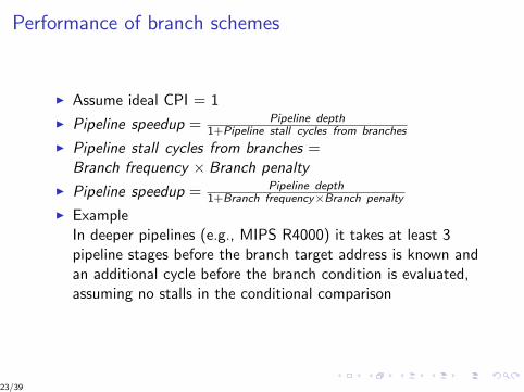
I Assume ideal CPI = 1
I Pipeline speedup = Pipeline depth1+Pipeline stall cycles from branches
I Pipeline stall cycles from branches =Branch frequency × Branch penalty
I Pipeline speedup = Pipeline depth1+Branch frequency×Branch penalty
I ExampleIn deeper pipelines (e.g., MIPS R4000) it takes at least 3pipeline stages before the branch target address is known andan additional cycle before the branch condition is evaluated,assuming no stalls in the conditional comparison
23/39

Performance of branch schemes: Example
I Branch penalties for the 3 simplest prediction schemes areshown in Figure C15
I Find the effective CPI arising from branches for this pipeline,assuming the following frequencies
I Unconditional branch: 4%Conditional branch, untaken: 6%Conditional branch, taken : 10%
I CPI calculated by multiplying the relative frequencies by thecorresponding penalties: see Figure C16
I Note that the differences between schemes are increased withlonger delay
24/39

Branch penalties for prediction schemes
Branch scheme Penalty uncon-ditional
Penalty untaken Penalty taken
Flush pipeline 2 3 3
Predicted taken 2 3 2
Predicteduntaken
2 0 3
Table: Figure C15: Branch penalties for prediction schemes
25/39

CPI penalties for three branch prediction schemes and adeeper pipeline
Branchscheme
Unconditionalbranches
Untakenconditional
Taken con-ditional
All branches
Frequency ofevent
4% 6% 10% 20%
Stall pipeline 0.08 0.18 0.3 0.56
Predictedtaken
0.08 0.18 0.2 0.46
Predicteduntaken
0.08 0.00 0.3 0.38
Table: Figure 16: CPI penalties for three branch prediction schemes anda deeper pipeline
26/39

Reducing the cost of branches: Prediction
I Static prediction: uses information available at compile time
I Dynamic prediction: based on program behaviour
27/39

Static branch prediction
I Can improve compile-time prediction based on informationfrom earlier runs
I An individual branch is often biased towards taken or untaken
I Effectiveness of any branch prediction scheme depends on theaccuracy of the scheme and the frequency of conditionalbranches (3% to 24% in SPEC)
I The mis-prediction rate for integer programs is higher andthese usually have a higher branch frequency
I This limits the usefulness of static branch prediction
28/39

Dynamic branch prediction
I Simple scheme: Branch-prediction buffer
I A small memory indexed by the lower part of the address of the branchinstruction
I 1 bit to indicate branch taken/not taken
I Simple buffer, no tags
I Reduces branch delay when it is longer than the time to compute thepossible target PC
I Do not know if prediction is correct because many branches have somelow-order address bits.
I Prediction is a hint assumed correct, fetching begins in predicteddirection. If hint is wrong, prediction bit is inverted and stored.
I 1-bit prediction: assume branch almost always taken
I If branch not taken, this is a misprediction, bit changed next time, branchprediction = not taken, but branch is taken, a misprediction
I So incorrect prediction occurs twice on the less-taken path
I A 2-bit prediction scheme must miss twice before it is changed: seeFigure C18
29/39

Forwarding of operand required by stores during MEM
Copyright © 2011, Elsevier Inc. All rights Reserved. 11
Figure C.18 The states in a 2-bit prediction scheme. By using 2 bits rather than 1, a branch that strongly favors taken or not taken—as many branches do—will be mispredicted less often than with a 1-bit predictor. The 2 bits are used to encode the four states in the system. The 2-bit scheme is actually a specialization of a more general scheme that has an n-bit saturating counter for each entry in the prediction buffer. With an n-bit counter, the counter can take on values between 0 and 2n – 1: When the counter is greater than or equal to one-half of its maximum value (2n – 1), the branch is predicted as taken; otherwise, it is predicted as untaken. Studies of n-bit predictors have shown that the 2-bit predictors do almost as well, thus most systems rely on 2-bit branch predictors rather than the more general n-bit predictors.
Copyright c© 2011, Elsevier Inc. All rights reserved
30/39

Simple implementation of unpipelined MIPS
I Integer subset of MIPS
I Load/store word
I Branch if equal to zero
I Integer ALU operations
I Less aggressive branch implementation initially
I MIPS instruction implemented in at most 5 clock cycles
31/39

Implementation of unpipelined MIPS
1 Instruction fetch cycle (IF)I IF ← Mem[PC];
NPC ← PC+4;I Operation: IR used to hold instruction that is needed on
subsequent clock cyclesNPC holds next sequential PC
32/39
Implementation of unpipelined MIPS
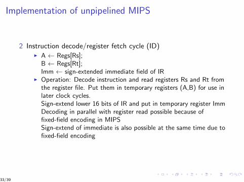
2 Instruction decode/register fetch cycle (ID)I A ← Regs[Rs];
B ← Regs[Rt];Imm ← sign-extended immediate field of IR
I Operation: Decode instruction and read registers Rs and Rt fromthe register file. Put them in temporary registers (A,B) for use inlater clock cycles.Sign-extend lower 16 bits of IR and put in temporary register ImmDecoding in parallel with register read possible because offixed-field encoding in MIPSSign-extend of immediate is also possible at the same time due tofixed-field encoding
33/39
Implementation of unpipelined MIPS
3 Execution/effective address cycle (EX)ALU performs 1 of 4 functions, depending on MIPS instructiontype
I Memory referenceALUOutput ← A + Imm;Operation: effective address formed and put in registerALUOutput
I Register-register ALU instruction ALUOutput ← A func B;Operation: Binary function func performed on A, B and resultput in register ALUOutput
I Register-immediate ALU instruction ALUOutput ← A op Imm;
34/39

Implementation of unpipelined MIPS
3 Execution/effective address cycle (EX) (continued)
I BranchALUOutput ← NPC + (Imm << 2);Cond ← (A == 0);Operation: The sign-extended immediate value in Imm ismultiplied by 4 to give a word offset and then added to NPC togive the branch target addressRegister A is checked to see if branch is takenOnly one branch is being considered, BEQZ, so comparison iswith 0Note BEQZ is a pseudo-instruction that translates to BEQ withR0 as an operandThe load-store architecture of MIPS allows effective address andexecution cycles to be combined in a single clock cycleInstructions not included are various jumps, similar to branches
35/39

Implementation of unpipelined MIPS
4 Memory access/branch completion cycle (MEM)
I ∀ instructions : PC ← NPC ;I Memory reference
LMD ← Mem[ALUOutput] or Mem[ALUOutput] ← B;
I Operation: Access memory if needed. If instruction is a load, putdata from memory in LMD (load memory data) register. Ifinstruction is a store, write data from the B register into memory
I BranchIf (cond) PC ← ALUOutput
I Operation: If the instruction branches, use the target address inALUOutput
36/39

Implementation of unpipelined MIPS
5 Write-back cycle (WB)I Register-register ALU instruction
Regs[Rd] ← ALUOutput;I Register-immediate ALU instruction
Regs[Rt] ← ALUOutput;I Load instruction
Regs[Rt] ← LMD;I Operation: Write the result to the register file
If instruction is load, source = LMD, dest = RtIf instruction is ALU, source = ALUOutput
Figure C21 shows the data path
37/39

MIPS data path implementation (unpipelined)
Copyright © 2011, Elsevier Inc. All rights Reserved. 14
Figure C.21 The implementation of the MIPS data path allows every instruction to be executed in 4 or 5 clock cycles. Although the PC is shown in the portion of the data path that is used in instruction fetch and the registers are shown in the portion of the data path that is used in instruction decode/register fetch, both of these functional units are read as well as written by an instruction. Although we show these functional units in the cycle corresponding to where they are read, the PC is written during the memory access clock cycle and the registers are written during the write-back clock cycle. In both cases, the writes in later pipe stages are indicated by the multiplexer output (in memory access or write-back), which carries a value back to the PC or registers. These backward-flowing signals introduce much of the complexity of pipelining, since they indicate the possibility of hazards.
Copyright c© 2011, Elsevier Inc. All rights reserved
38/39

Implementation of unpipelined MIPS
I At the end of each clock cycle, every value computed during that clockcycle and needed on a later clock cycle (in this instruction or the next) iswritten into a storage device
I The temporary registers hold values between clock cycles for 1 instruction
I Other storage elements hold values between successive instructions
I This multi-cycle implementation approximates early processor designs
I Microcode control could be used to give a more complex processor
I Hardware redundancies could be removed but are left here to give a basefor a pipelined implementation
I For example, there are 2 ALUs: one to increment the PC andone for ea and ALU computation. Since they are not neededon the same clock cycle, they could be merged by using extramultiplexers.
I It is also possible in this unpipelined processor to store dataand instructions in the same memory.
39/39