Embed Size (px)
Citation preview

CS311 Lecture: Sequential Circuits
Last revised 8/15/2007
Objectives:
1. To introduce asynchronous and synchronous flip-flops (latches and pulse-triggered, plus asynchronous preset/clear)
2. To introduce SR, D, and JK configurations3. To show how to implement a finite state machine using flip-flops and
combinatorial networks
Materials:
1. Circuit Sandbox and demonstration circuits Asynchronous Flip Flop, Latch, Race, Master-Slave, Master-Slave with Preset+Clear, D Flip-Flop, JK Flip-Flop, Traffic Light Controller, Traffic Light Controller with Walk Flip-Flop, Divide by Three Counter
I. Introduction
A. Thus far, we have been discussing COMBINATORIAL logic circuits. These have the property that the output at any time is a boolean function of the inputs (with some propagation delay when inputs change).
B. Complete computer systems also require circuits that have MEMORY - that is, circuits whose output can be a function of the input AT SOME TIME in the past. Such circuits are used for:
1. Internal memory: registers, main memory
2. Control circuits that cycle the system through the series of steps comprising the algorithm for a given task. (The system must keep track of its state - what step it is currently on - in order to know what to do next.
II. Flip Flops
A. It turns out to be quite easy to use our combinatorial building blocks to construct a circuit that has memory - i.e. whose output is a function of past as well as present inputs.
The following is an example of such a circuit, called a flip-flop:
1
Suppose we were to try to develop a “truth table” for this circuit, where we treat S' and R' as inputs and Q and Q' as outputs.ASK CLASS FOR OUTPUTS FOR EACH ROWS' R' Q Q'0 0 1 10 1 1 01 0 0 11 1 ??? - depends on prior values
Observe:
1. When both S' and R' are high (1), there are two stable states:
a) If Q is low, then Q' is high (since the lower gate now has one low input and one high.) This state is stable, since the upper NAND gate now has two high inputs, making its output low.
b) If Q is high, then Q' is low (since the lower gate has both inputs high). This state is also stable, since the upper NAND gate has one low input and one high input, making its output high.
c) When the circuit is first turned on, the flip flop will go into one of these two states non-deterministically. (Actually, slight physical differences in the transistors in the two gates will usually serve to decide the state.
d) The two stable states are conventionally called 0 and 1 or low and high, corresponding to the value of Q.
e) Note the relationship of Q and Q' when in a stable state: they are inverses (hence the choice of labels Q and Q')
2
2. Effect of momentarily setting either S' or R' to low (0).
a) If the flip-flop is in the stable state with Q low then setting R' low has no effect. However, setting S' low flips the state to the state with Q high, where the circuit will remain even after S returns to high.The input is labelled R' because it is ACTIVE LOW, and its effect is to reset the flip-flop (put it in the 0 state). (Note: sometimes documentation just calls this input R, rather than R-bar).
b) If the flip-flop is in the stable state with Q high then setting S' low has no effect. However, setting R' low flips the state to the state with Q low, where the circuit will remain even after R returns to high.The input is labelled S' because it is ACTIVE LOW, and its effect is to set the flip-flop (put it in the 1 state). (Note: sometimes documentation just calls this input S, rather than S-bar).
3. Effect of momentarily setting both S' and R' low:
a) If both S' and R' are low, then both Q and Q' go high, since each gate now has one low input. This, of course, violates the intention of the labels that Q and Q' should be opposites.
b) If both S' and R' are restored to the high state at the exact same time, the state of the flip flop is intedeterminate: it will settle into one of the two stable states. Which one, however, cannot be predicted.
c) For these reasons, having both R' and S' low at the same time is regarded as an illegal input pattern for this kind of flip-flop.
4. DEMONSTRATE (File Asynchronous SR flip-flop)
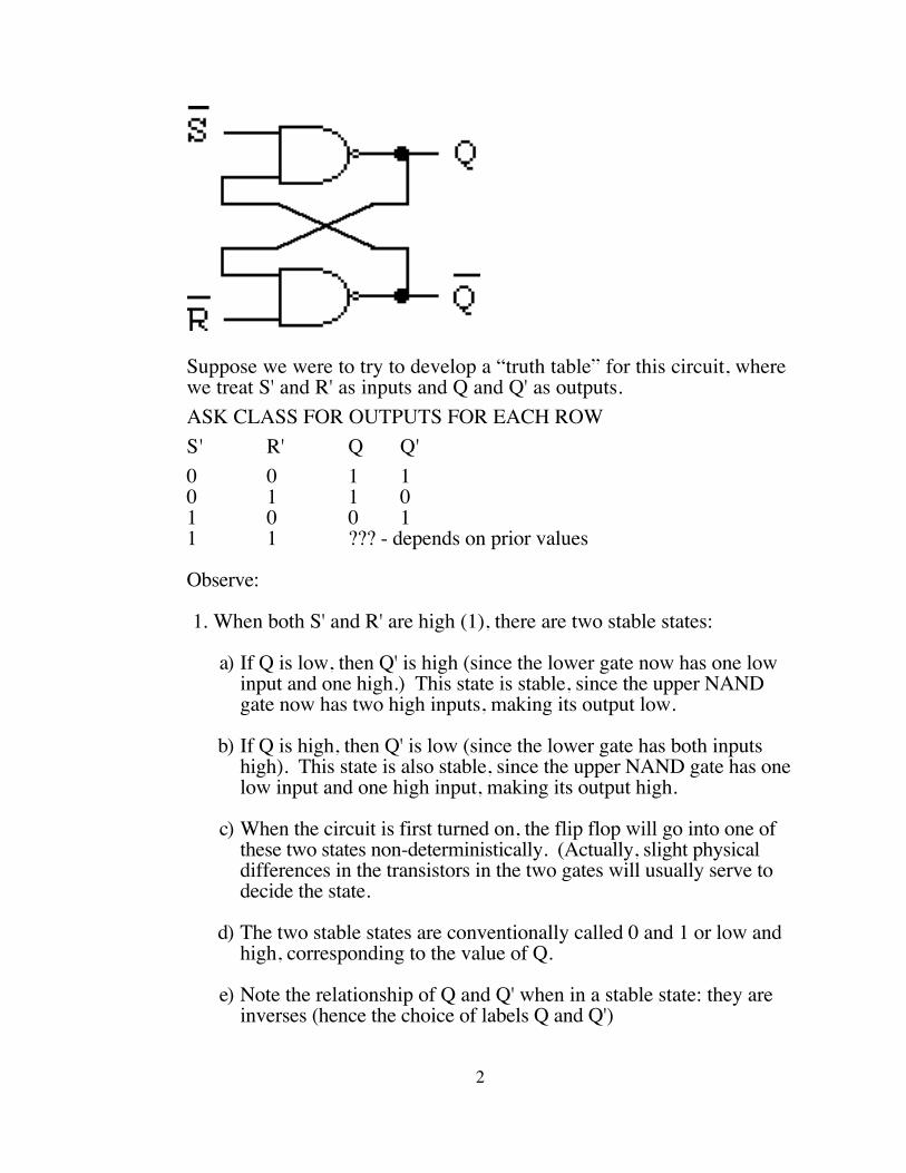
5. This is variously called an RS flip-flop or an SR flip-flop, and has its own special symbol:
6. One can build a similar circuit from NOR gates - but we won't pursue this here.
3
B. One important characteristic of the flip flop we have been considering is that it is ASYNCHRONOUS - that is, the output changes almost instantaneously when the input changes. (There is a slight delay due to internal switching times of the gate.) 1. This can pose a problem if one builds a register, in which several flip-
flops are used to represent a multi-bit value (e.g. 32 flip-flops could bu used to represent a 32 bit number). In this case, one would like all the flip-flops to change state at the same time - which we call SYNCHRONOUS behavior. (The state changes are synchronized)
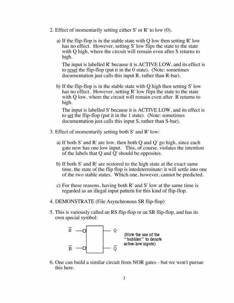
2. One can easily build a clocked variant of this kind of flip flop, in which the state changes only when a special clock pulse is received. This makes it possible to synchronize state changes. The following has the property that state changes occur only when the clock input is high:
a) When the clock input is low (0), the outputs of both gates are necessarily high (1) - which ensures that the flip-flop will remain in whatever state it is in, regardless of the external inputs.
b) When the clock input is high (1), and both S and R are low (0), the output of both gates is again high, which leaves the state of the flip-flop unchanged.
c) When the clock input is high, a high on either S or R becomes a low at the output of the corresponding gate, which in turn sets or clears the flip-flop.
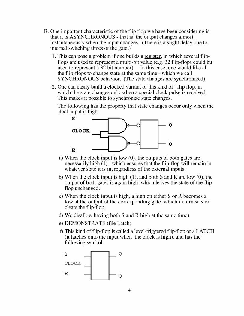
d) We disallow having both S and R high at the same time)e) DEMONSTRATE (file Latch)f) This kind of flip-flop is called a level-triggered flip-flop or a LATCH
(it latches onto the input when the clock is high), and has the following symbol:
4

C. However, even this device is not adequate for all situations.
1. Consider what would be inolved in building a flip-flop whose output feeds back to its input. Such a situation might arise, for example, if one were trying to build a COUNTER - a device that counts the number of clock pulses it receives. For example, the following is a one-bit counter - it is intended to go through the sequence of states 0, 1, 0 , 1, 0, 1 ...
This circuit will not work as intended. Why?
ASK
There is a race condition in the circuit - if the clock remains high after the output has changed state, the flip flop will change state again, and again, and again. To get the desired behavior, the clock would have to be high just long enough for one state change to occur - a critical time that actually varies slightly from gate to gate due to slight variations in manufacturing.
DEMONSTRATE - file Race. Set simulation speed to 1 second before running. (note: the Circuit Sandbox simulation includes a reset circuit that is needed to start the flip-flop off in a known state. The switch is off to reset, on to allow the counter to run.)
2. To prevent race conditions such as this, it is possible to consturct a clocked flip-flops that changes state on a PULSE or an EDGE, rather than on a clock LEVEL. For example, the following flip-flop changes state just when the clock transitions from high back to low. (Note: the outlined portion is internal and is not visible to the user - it’s a “black box”. The user sees only the inputs S, R, and CLOCK and the two ouputs.)
5
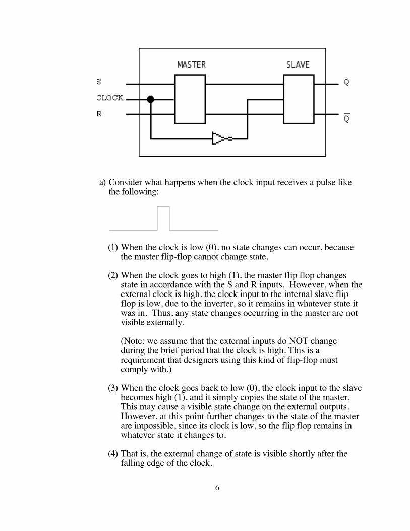
a) Consider what happens when the clock input receives a pulse like the following:
(1) When the clock is low (0), no state changes can occur, because the master flip-flop cannot change state.
(2) When the clock goes to high (1), the master flip flop changes state in accordance with the S and R inputs. However, when the external clock is high, the clock input to the internal slave flip flop is low, due to the inverter, so it remains in whatever state it was in. Thus, any state changes occurring in the master are not visible externally.
(Note: we assume that the external inputs do NOT change during the brief period that the clock is high. This is a requirement that designers using this kind of flip-flop must comply with.)
(3) When the clock goes back to low (0), the clock input to the slave becomes high (1), and it simply copies the state of the master. This may cause a visible state change on the external outputs. However, at this point further changes to the state of the master are impossible, since its clock is low, so the flip flop remains in whatever state it changes to.
(4) That is, the external change of state is visible shortly after the falling edge of the clock.
6
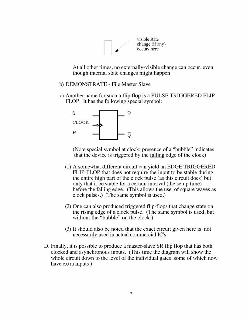
visible statechange (if any)occurs here
At all other times, no externally-visible change can occur, even though internal state changes might happen
b) DEMONSTRATE - File Master Slave
c) Another name for such a flip flop is a PULSE TRIGGERED FLIP-FLOP. It has the following special symbol:
(Note special symbol at clock; presence of a “bubble” indicates that the device is triggered by the falling edge of the clock)
(1) A somewhat different circuit can yield an EDGE TRIGGERED FLIP-FLOP that does not require the input to be stable during the entire high part of the clock pulse (as this circuit does) but only that it be stable for a certain interval (the setup time) before the falling edge. (This allows the use of square waves as clock pulses.) (The same symbol is used.)
(2) One can also produced triggered flip-flops that change state on the rising edge of a clock pulse. (The same symbol is used, but without the “bubble” on the clock.)
(3) It should also be noted that the exact circuit given here is not necessarily used in actual commercial IC's.
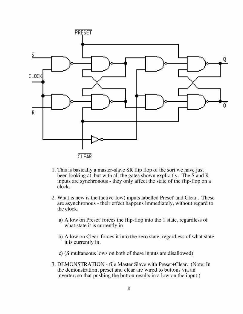
D. Finally, it is possible to produce a master-slave SR flip flop that has both clocked and asynchronous inputs. (This time the diagram will show the whole circuit down to the level of the individual gates, some of which now have extra inputs.)
7
E.
1. This is basically a master-slave SR flip flop of the sort we have just been looking at, but with all the gates shown explicitly. The S and R inputs are synchronous - they only affect the state of the flip-flop on a clock.
2. What is new is the (active-low) inputs labelled Preset' and Clear'. These are asynchronous - their effect happens immediately, without regard to the clock.
a) A low on Preset' forces the flip-flop into the 1 state, regardless of what state it is currently in.
b) A low on Clear' forces it into the zero state, regardless of what state it is currently in.
c) (Simultaneous lows on both of these inputs are disallowed)
3. DEMONSTRATION - file Master Slave with Preset+Clear. (Note: In the demonstration, preset and clear are wired to buttons via an inverter, so that pushing the button results in a low on the input.)
8
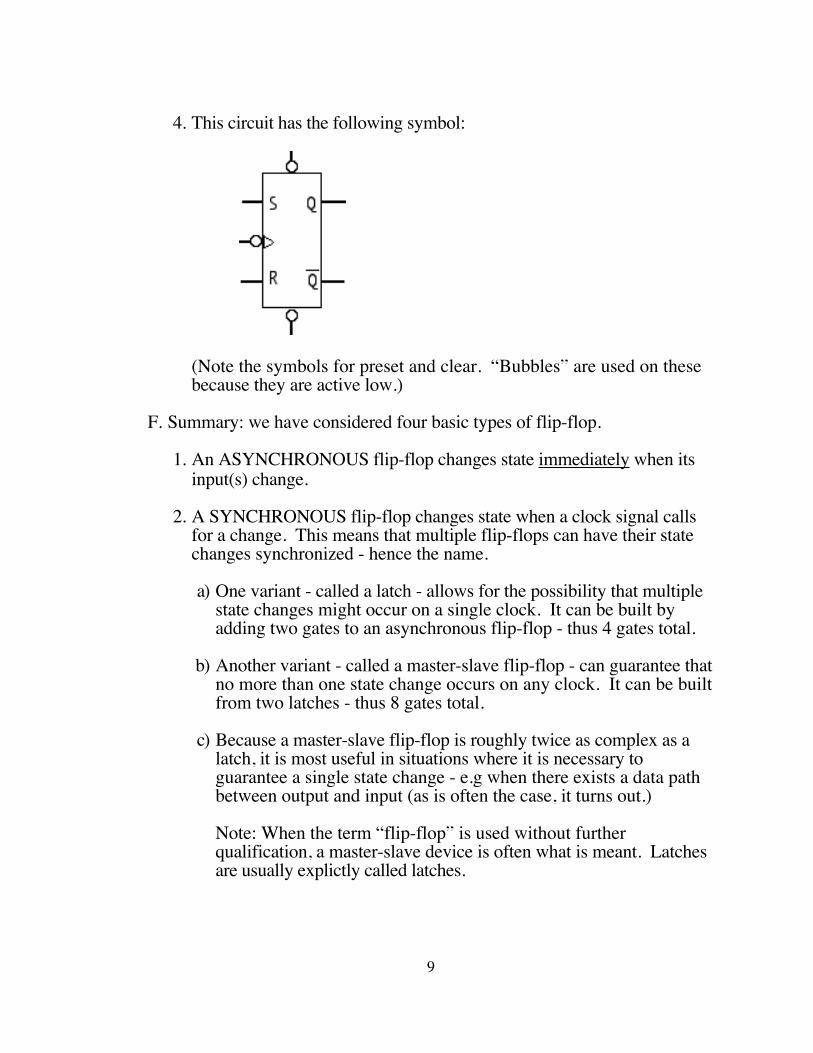
4. This circuit has the following symbol:
(Note the symbols for preset and clear. “Bubbles” are used on these because they are active low.)
F. Summary: we have considered four basic types of flip-flop.
1. An ASYNCHRONOUS flip-flop changes state immediately when its input(s) change.
2. A SYNCHRONOUS flip-flop changes state when a clock signal calls for a change. This means that multiple flip-flops can have their state changes synchronized - hence the name.
a) One variant - called a latch - allows for the possibility that multiple state changes might occur on a single clock. It can be built by adding two gates to an asynchronous flip-flop - thus 4 gates total.
b) Another variant - called a master-slave flip-flop - can guarantee that no more than one state change occurs on any clock. It can be built from two latches - thus 8 gates total.
c) Because a master-slave flip-flop is roughly twice as complex as a latch, it is most useful in situations where it is necessary to guarantee a single state change - e.g when there exists a data path between output and input (as is often the case, it turns out.)
Note: When the term “flip-flop” is used without further qualification, a master-slave device is often what is meant. Latches are usually explictly called latches.
9
3. Finally, we considered the possibility of incorporating both synchronous and asynchronous behavior in the same device by adding clear and/or preset inputs to a synchronous device (this could be either a latch or a master-slave flip-flop, though the example we used was a master-slave.)
It is common to find that a hardware device incorporates a “power-up reset” circuit that puts flip flops into a known initial state (often 0) when the power is first turned on. Thus, one may find a flip-flop that has just a clear input, without a preset. (It would be rare to find the reverse.)
III. Other Flip-Flop Circuits
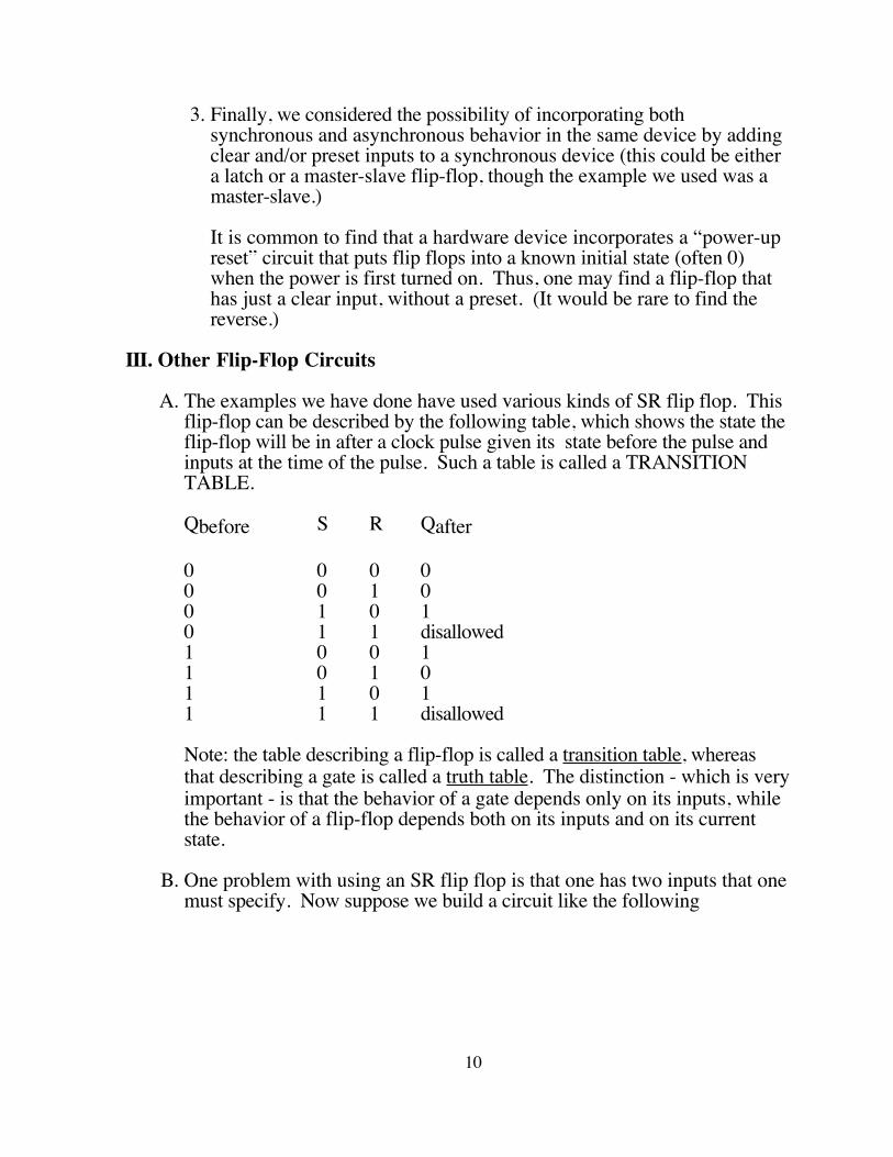
A. The examples we have done have used various kinds of SR flip flop. This flip-flop can be described by the following table, which shows the state the flip-flop will be in after a clock pulse given its state before the pulse and inputs at the time of the pulse. Such a table is called a TRANSITION TABLE.
Qbefore S R Qafter
0 0 0 00 0 1 00 1 0 10 1 1 disallowed1 0 0 11 0 1 01 1 0 11 1 1 disallowed
Note: the table describing a flip-flop is called a transition table, whereas that describing a gate is called a truth table. The distinction - which is very important - is that the behavior of a gate depends only on its inputs, while the behavior of a flip-flop depends both on its inputs and on its current state.
B. One problem with using an SR flip flop is that one has two inputs that one must specify. Now suppose we build a circuit like the following
10
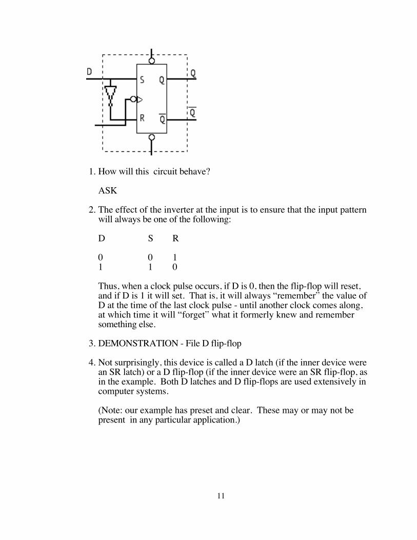
1. How will this circuit behave?
ASK
2. The effect of the inverter at the input is to ensure that the input pattern will always be one of the following:
D S R
0 0 11 1 0
Thus, when a clock pulse occurs, if D is 0, then the flip-flop will reset, and if D is 1 it will set. That is, it will always “remember” the value of D at the time of the last clock pulse - until another clock comes along, at which time it will “forget” what it formerly knew and remember something else.
3. DEMONSTRATION - File D flip-flop
4. Not surprisingly, this device is called a D latch (if the inner device were an SR latch) or a D flip-flop (if the inner device were an SR flip-flop, as in the example. Both D latches and D flip-flops are used extensively in computer systems.
(Note: our example has preset and clear. These may or may not be present in any particular application.)
11
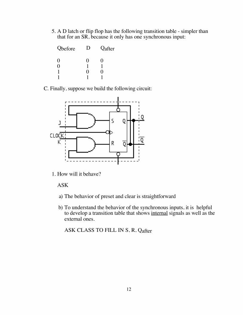
5. A D latch or flip flop has the following transition table - simpler than that for an SR, because it only has one synchronous input:
Qbefore D Qafter
0 0 00 1 11 0 01 1 1
C. Finally, suppose we build the following circuit:
1. How will it behave?
ASK
a) The behavior of preset and clear is straightforward
b) To understand the behavior of the synchronous inputs, it is helpful to develop a transition table that shows internal signals as well as the external ones.
ASK CLASS TO FILL IN S, R, Qafter
12
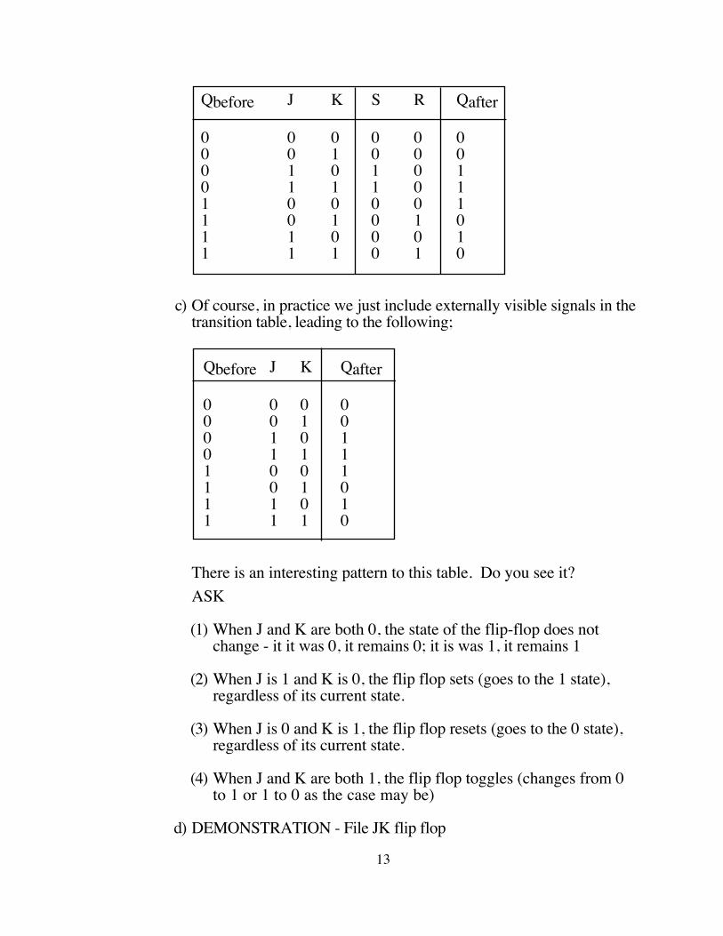
Qbefore J K S R Qafter
0 0 0 0 0 00 0 1 0 0 00 1 0 1 0 10 1 1 1 0 11 0 0 0 0 11 0 1 0 1 01 1 0 0 0 11 1 1 0 1 0
c) Of course, in practice we just include externally visible signals in the transition table, leading to the following;
Qbefore J K Qafter
0 0 0 00 0 1 00 1 0 10 1 1 11 0 0 11 0 1 01 1 0 11 1 1 0
There is an interesting pattern to this table. Do you see it?ASK
(1) When J and K are both 0, the state of the flip-flop does not change - it it was 0, it remains 0; it is was 1, it remains 1
(2) When J is 1 and K is 0, the flip flop sets (goes to the 1 state), regardless of its current state.
(3) When J is 0 and K is 1, the flip flop resets (goes to the 0 state), regardless of its current state.
(4) When J and K are both 1, the flip flop toggles (changes from 0 to 1 or 1 to 0 as the case may be)
d) DEMONSTRATION - File JK flip flop
13

2. The transition table is used when we want to do analysis - i.e. given a circuit, how does it behave. It is also possible to do synthesis - i.e. given a desired behavior, design a circuit that exhibits it. For this, we use a different tool called an EXCITATION TABLE, which answers the question “if I’m in __ state, what J/K values do I need to get to ___ state?
This table can be constructed from the transition table. For each row, one of the two values J and K will be specified, and the other will be a don’t care.
ASK class to provide J and K values
Qcurrent Qdesired J K
0 0 0 -0 1 1 -1 0 - 11 1 - 0
That is, if the flip-flop is currently in the 0 state, only the “J” value affects the next state (since K is anded with a 0); if it is in the 1 state, only the “K” value matters
3. A few observations
a) The JK flip-flop is the most general type of flip-flop. For this reason, JK's are the most broadly useful type. Though D's have the advantage of one fewer input, with a JK in any given state only one of the two inputs matters anyhow.
b) JK flip-flops are only useful as master-slave flip-flops; there is no such thing as a JK Latch. Why?
ASK
The circuit itself contains feedback from the outputs to the input.
c) In practice, JK flip flops are implemented by folding the and gates at the input in with the initial nand gates of the SR - e.g. instead of
14
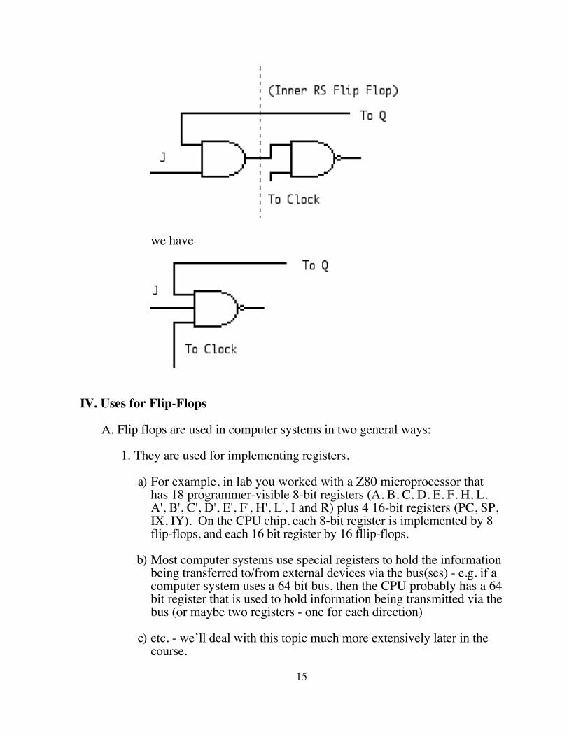
we have
IV. Uses for Flip-Flops
A. Flip flops are used in computer systems in two general ways:
1. They are used for implementing registers.
a) For example, in lab you worked with a Z80 microprocessor that has 18 programmer-visible 8-bit registers (A, B, C, D, E, F, H, L, A', B', C', D', E', F', H', L', I and R) plus 4 16-bit registers (PC, SP, IX, IY). On the CPU chip, each 8-bit register is implemented by 8 flip-flops, and each 16 bit register by 16 fllip-flops.
b) Most computer systems use special registers to hold the information being transferred to/from external devices via the bus(ses) - e.g. if a computer system uses a 64 bit bus, then the CPU probably has a 64 bit register that is used to hold information being transmitted via the bus (or maybe two registers - one for each direction)
c) etc. - we’ll deal with this topic much more extensively later in the course.
15
2. They are used in building state machines. Any finite state machine (as discussed in CS220) can be implemented by using one or more flip flops plus combinatorial networks, following an approach we will discuss now, with a clock used for synchronization.
B. Sequential circuits are most easily designed or analyzed by working with a STATE DIAGRAM. Each state represents one possible value of the different flip-flops - i.e. a sequential circuit with n flip flops can have up to 2n states. Edges between states, labelled with possible inputs, show the various transitions between states.
C. As an example of designing a sequential control circuit this way, consider a controller for a traffic light to be positioned at an intersection between a north-south and an east-west street.
1. Specifications.
a) For simplicity, we assume only red and green lights plus a walk light, so that the following patterns may be displayed:N-S street E-W streetR GG RWalk Walk
b) Ordinarily, the light changes from one Green-Red state to the other every 30 seconds.
c) However, if a pedestrian is pushing a walk button at the time of a change, then he gets a 30 second walk cycle. (This is unrealistic; normally the system would remember any push of the button within the cycle. We could add this simply later.
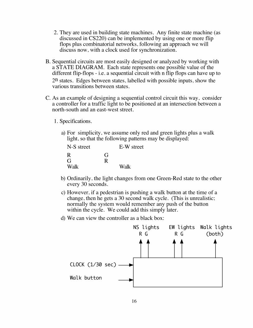
d) We can view the controller as a black box:
CLOCK (1/30 sec)
Walk button
NS lights R G
EW lights R G
Walk lights (both)
16
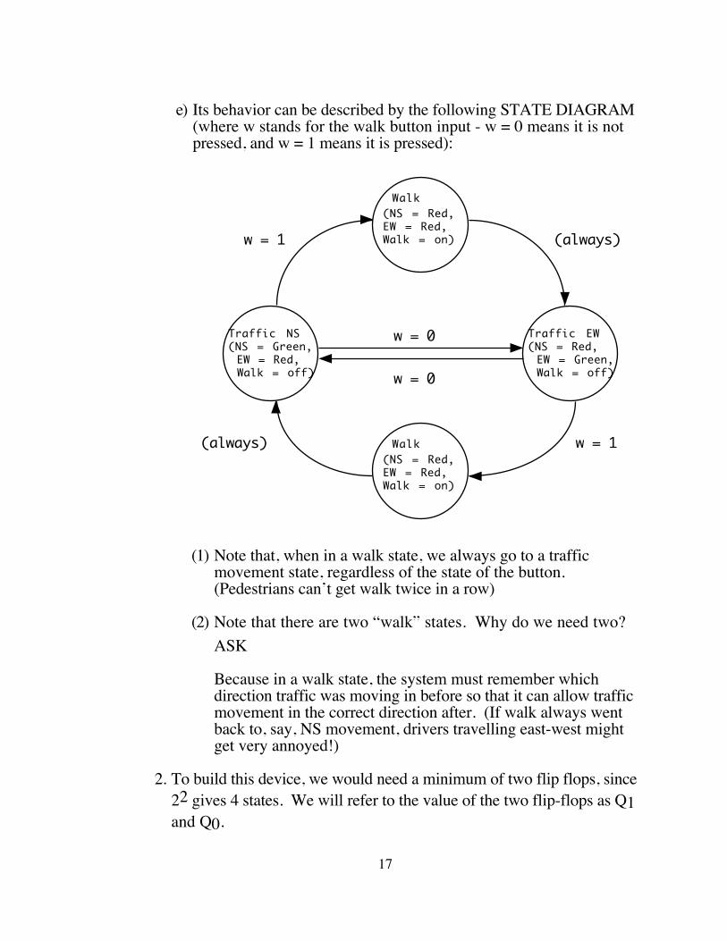
e) Its behavior can be described by the following STATE DIAGRAM (where w stands for the walk button input - w = 0 means it is not pressed, and w = 1 means it is pressed):
Traffic NS(NS = Green, EW = Red, Walk = off)
Walk(NS = Red,EW = Red,Walk = on)
w = 0
w = 0
w = 1
w = 1
(always)
(always) Walk(NS = Red,EW = Red,Walk = on)
Traffic EW(NS = Red, EW = Green, Walk = off)
(1) Note that, when in a walk state, we always go to a traffic movement state, regardless of the state of the button. (Pedestrians can’t get walk twice in a row)
(2) Note that there are two “walk” states. Why do we need two?ASK
Because in a walk state, the system must remember which direction traffic was moving in before so that it can allow traffic movement in the correct direction after. (If walk always went back to, say, NS movement, drivers travelling east-west might get very annoyed!)
2. To build this device, we would need a minimum of two flip flops, since 22 gives 4 states. We will refer to the value of the two flip-flops as Q1 and Q0.
17
a) One immediate question is how to associate flip flop values with states. We will (arbitrarily) choose the following pattern. (In practice, one may consider several different assignments and choose the one giving the simplest overall circuit.)
State Flip flop values (Q1Q0)
NS traffic 00Walk after NS 01EW traffic 10Walk after EW 11
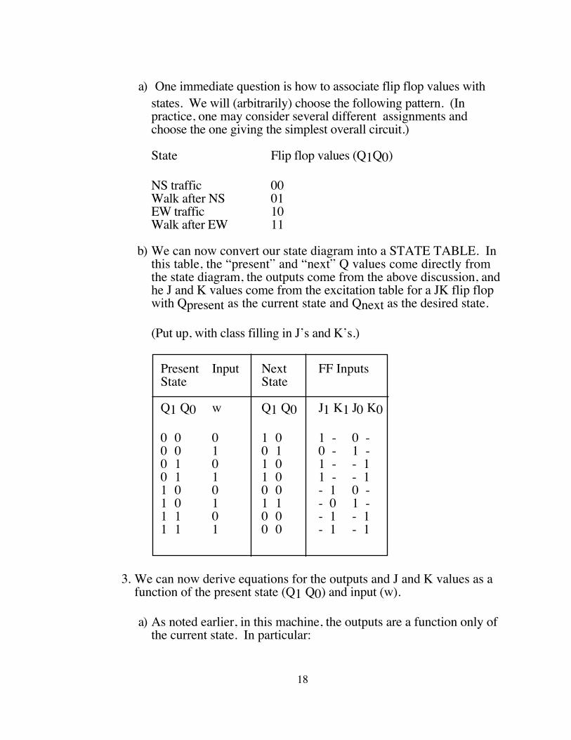
b) We can now convert our state diagram into a STATE TABLE. In this table, the “present” and “next” Q values come directly from the state diagram, the outputs come from the above discussion, and he J and K values come from the excitation table for a JK flip flop with Qpresent as the current state and Qnext as the desired state.
(Put up, with class filling in J’s and K’s.)
Present Input Next FF InputsState State
Q1 Q0 w Q1 Q0 J1 K1 J0 K0
0 0 0 1 0 1 - 0 -0 0 1 0 1 0 - 1 -0 1 0 1 0 1 - - 10 1 1 1 0 1 - - 11 0 0 0 0 - 1 0 -1 0 1 1 1 - 0 1 -1 1 0 0 0 - 1 - 11 1 1 0 0 - 1 - 1
3. We can now derive equations for the outputs and J and K values as a function of the present state (Q1 Q0) and input (w).
a) As noted earlier, in this machine, the outputs are a function only of the current state. In particular:
18
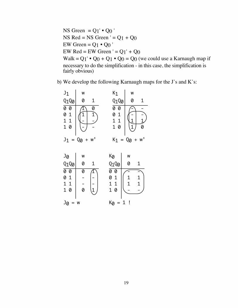
NS Green = Q1' • Q0 ' NS Red = NS Green ' = Q1 + Q0 EW Green = Q1 • Q0 'EW Red = EW Green ' = Q1' + Q0Walk = Q1' • Q0 + Q1 • Q0 = Q0 (we could use a Karnaugh map if necessary to do the simplification - in this case, the simplification is fairly obvious)
b) We develop the following Karnaugh maps for the J’s and K’s:
J1 wQ1Q0 0 10 0 1 00 1 1 11 1 - -1 0 - -
J1 = Q0 + w’
K1 wQ1Q0 0 10 0 - -0 1 - -1 1 1 11 0 1 0
K1 = Q0 + w’
J0 wQ1Q0 0 10 0 0 10 1 - -1 1 - -1 0 0 1
J0 = w
K0 wQ1Q0 0 10 0 - -0 1 1 11 1 1 11 0 - -
K0 = 1 !
19
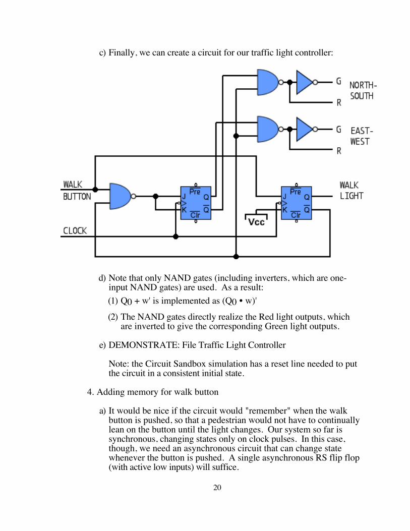
c) Finally, we can create a circuit for our traffic light controller:
d) Note that only NAND gates (including inverters, which are one-input NAND gates) are used. As a result:(1) Q0 + w' is implemented as (Q0 • w)'
(2) The NAND gates directly realize the Red light outputs, which are inverted to give the corresponding Green light outputs.
e) DEMONSTRATE: File Traffic Light Controller
Note: the Circuit Sandbox simulation has a reset line needed to put the circuit in a consistent initial state.
4. Adding memory for walk button
a) It would be nice if the circuit would "remember" when the walk button is pushed, so that a pedestrian would not have to continually lean on the button until the light changes. Our system so far is synchronous, changing states only on clock pulses. In this case, though, we need an asynchronous circuit that can change state whenever the button is pushed. A single asynchronous RS flip flop (with active low inputs) will suffice.
20
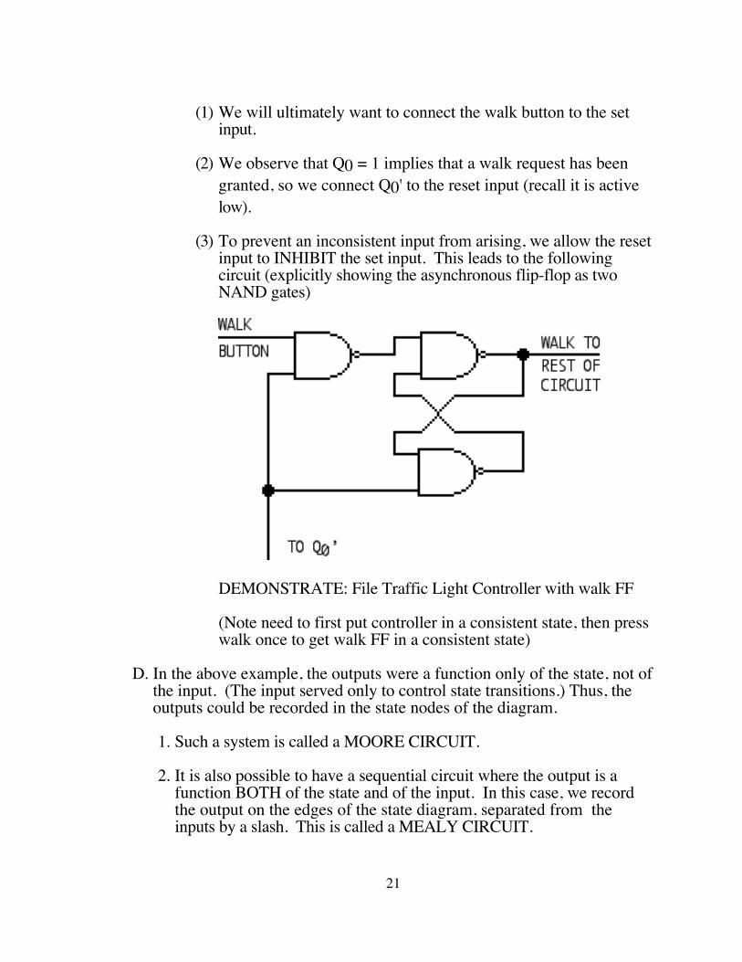
(1) We will ultimately want to connect the walk button to the set input.
(2) We observe that Q0 = 1 implies that a walk request has been granted, so we connect Q0' to the reset input (recall it is active low).
(3) To prevent an inconsistent input from arising, we allow the reset input to INHIBIT the set input. This leads to the following circuit (explicitly showing the asynchronous flip-flop as two NAND gates)
DEMONSTRATE: File Traffic Light Controller with walk FF
(Note need to first put controller in a consistent state, then press walk once to get walk FF in a consistent state)
D. In the above example, the outputs were a function only of the state, not of the input. (The input served only to control state transitions.) Thus, the outputs could be recorded in the state nodes of the diagram.
1. Such a system is called a MOORE CIRCUIT.
2. It is also possible to have a sequential circuit where the output is a function BOTH of the state and of the input. In this case, we record the output on the edges of the state diagram, separated from the inputs by a slash. This is called a MEALY CIRCUIT.
21
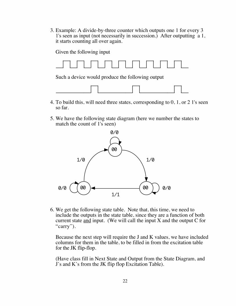
3. Example: A divide-by-three counter which outputs one 1 for every 3 1's seen as input (not necessarily in succession.) After outputting a 1, it starts counting all over again.
Given the following input
Such a device would produce the following output
4. To build this, will need three states, corresponding to 0, 1, or 2 1's seen so far.
5. We have the following state diagram (here we number the states to match the count of 1's seen)
1/0 1/0
1/10000
00
0/0
0/00/0
6. We get the following state table. Note that, this time, we need to include the outputs in the state table, since they are a function of both current state and input. (We will call the input X and the output C for “carry”).
Because the next step will require the J and K values, we have included columns for them in the table, to be filled in from the excitation table for the JK flip-flop.
(Have class fill in Next State and Output from the State Diagram, and J’s and K’s from the JK flip flop Excitation Table).
22
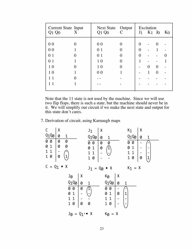
Current State Input Next State Output ExcitationQ1 Q0 X Q1 Q0 C J1 K1 J0 K0
0 0 0 0 0 0 0 - 0 -0 0 1 0 1 0 0 - 1 -0 1 0 0 1 0 0 - - 00 1 1 1 0 0 1 - - 11 0 0 1 0 0 - 0 0 -1 0 1 0 0 1 - 1 0 -1 1 0 - - - - - - -1 1 1 - - - - - - -
Note that the 11 state is not used by the machine. Since we will use two flip flops, there is such a state, but the machine should never be in it. We will simplify our circuit if we make the next state and output for this state don’t cares.
7. Derivation of circuit, using Karnaugh maps
J1 XQ1Q0 0 10 0 0 00 1 0 11 1 - -1 0 - -
J1 = Q0 • X
K1 XQ1Q0 0 10 0 - -0 1 - -1 1 - -1 0 0 1
K1 = X
C XQ1Q0 0 10 0 0 00 1 0 01 1 - -1 0 0 1
C = Q1 • X
J0 XQ1Q0 0 10 0 0 10 1 - -1 1 - -1 0 0 0
J0 = Q1'• X
K0 XQ1Q0 0 10 0 - -0 1 0 11 1 - -1 0 - -
K0 = X
23
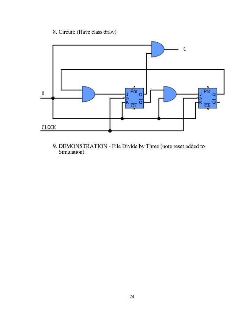
8. Circuit: (Have class draw)
9. DEMONSTRATION - File Divide by Three (note reset added to Simulation)
24