Embed Size (px)
Citation preview

CS240 and CS240DM
PT-1000 Class A, Back-of-Module
Temperature Sensors
Revision: 7/18 Copyright © 2017 – 2018 Campbell Scientific, Inc.


Limited Warranty “Products manufactured by CSI are warranted by CSI to be free from defects in materials and workmanship under normal use and service for twelve months from the date of shipment unless otherwise specified in the corresponding product manual. (Product manuals are available for review online at www.campbellsci.com.) Products not manufactured by CSI, but that are resold by CSI, are warranted only to the limits extended by the original manufacturer. Batteries, fine-wire thermocouples, desiccant, and other consumables have no warranty. CSI’s obligation under this warranty is limited to repairing or replacing (at CSI’s option) defective Products, which shall be the sole and exclusive remedy under this warranty. The Customer assumes all costs of removing, reinstalling, and shipping defective Products to CSI. CSI will return such Products by surface carrier prepaid within the continental United States of America. To all other locations, CSI will return such Products best way CIP (port of entry) per Incoterms ® 2010. This warranty shall not apply to any Products which have been subjected to modification, misuse, neglect, improper service, accidents of nature, or shipping damage. This warranty is in lieu of all other warranties, expressed or implied. The warranty for installation services performed by CSI such as programming to customer specifications, electrical connections to Products manufactured by CSI, and Product specific training, is part of CSI's product warranty. CSI EXPRESSLY DISCLAIMS AND EXCLUDES ANY IMPLIED WARRANTIES OF MERCHANTABILITY OR FITNESS FOR A PARTICULAR PURPOSE. CSI hereby disclaims, to the fullest extent allowed by applicable law, any and all warranties and conditions with respect to the Products, whether express, implied or statutory, other than those expressly provided herein.”

Assistance Products may not be returned without prior authorization. The following contact information is for US and international customers residing in countries served by Campbell Scientific, Inc. directly. Affiliate companies handle repairs for customers within their territories. Please visit www.campbellsci.com to determine which Campbell Scientific company serves your country.
To obtain a Returned Materials Authorization (RMA) number, contact CAMPBELL SCIENTIFIC, INC., phone (435) 227-9000. Please write the issued RMA number clearly on the outside of the shipping container. Campbell Scientific’s shipping address is:
CAMPBELL SCIENTIFIC, INC. RMA#_____ 815 West 1800 North Logan, Utah 84321-1784
For all returns, the customer must fill out a “Statement of Product Cleanliness and Decontamination” form and comply with the requirements specified in it. The form is available from our website at www.campbellsci.com/repair. A completed form must be either emailed to [email protected] or faxed to (435) 227-9106. Campbell Scientific is unable to process any returns until we receive this form. If the form is not received within three days of product receipt or is incomplete, the product will be returned to the customer at the customer’s expense. Campbell Scientific reserves the right to refuse service on products that were exposed to contaminants that may cause health or safety concerns for our employees.

Safety DANGER — MANY HAZARDS ARE ASSOCIATED WITH INSTALLING, USING, MAINTAINING, AND WORKING ON OR AROUND TRIPODS, TOWERS, AND ANY ATTACHMENTS TO TRIPODS AND TOWERS SUCH AS SENSORS, CROSSARMS, ENCLOSURES, ANTENNAS, ETC. FAILURE TO PROPERLY AND COMPLETELY ASSEMBLE, INSTALL, OPERATE, USE, AND MAINTAIN TRIPODS, TOWERS, AND ATTACHMENTS, AND FAILURE TO HEED WARNINGS, INCREASES THE RISK OF DEATH, ACCIDENT, SERIOUS INJURY, PROPERTY DAMAGE, AND PRODUCT FAILURE. TAKE ALL REASONABLE PRECAUTIONS TO AVOID THESE HAZARDS. CHECK WITH YOUR ORGANIZATION'S SAFETY COORDINATOR (OR POLICY) FOR PROCEDURES AND REQUIRED PROTECTIVE EQUIPMENT PRIOR TO PERFORMING ANY WORK.
Use tripods, towers, and attachments to tripods and towers only for purposes for which they are designed. Do not exceed design limits. Be familiar and comply with all instructions provided in product manuals. Manuals are available at www.campbellsci.com or by telephoning (435) 227-9000 (USA). You are responsible for conformance with governing codes and regulations, including safety regulations, and the integrity and location of structures or land to which towers, tripods, and any attachments are attached. Installation sites should be evaluated and approved by a qualified engineer. If questions or concerns arise regarding installation, use, or maintenance of tripods, towers, attachments, or electrical connections, consult with a licensed and qualified engineer or electrician.
General • Prior to performing site or installation work, obtain required approvals and permits. Comply
with all governing structure-height regulations, such as those of the FAA in the USA. • Use only qualified personnel for installation, use, and maintenance of tripods and towers, and
any attachments to tripods and towers. The use of licensed and qualified contractors is highly recommended.
• Read all applicable instructions carefully and understand procedures thoroughly before beginning work.
• Wear a hardhat and eye protection, and take other appropriate safety precautions while working on or around tripods and towers.
• Do not climb tripods or towers at any time, and prohibit climbing by other persons. Take reasonable precautions to secure tripod and tower sites from trespassers.
• Use only manufacturer recommended parts, materials, and tools.
Utility and Electrical • You can be killed or sustain serious bodily injury if the tripod, tower, or attachments you are
installing, constructing, using, or maintaining, or a tool, stake, or anchor, come in contact with overhead or underground utility lines.
• Maintain a distance of at least one-and-one-half times structure height, 20 feet, or the distance required by applicable law, whichever is greater, between overhead utility lines and the structure (tripod, tower, attachments, or tools).
• Prior to performing site or installation work, inform all utility companies and have all underground utilities marked.
• Comply with all electrical codes. Electrical equipment and related grounding devices should be installed by a licensed and qualified electrician.
Elevated Work and Weather • Exercise extreme caution when performing elevated work. • Use appropriate equipment and safety practices. • During installation and maintenance, keep tower and tripod sites clear of un-trained or non-
essential personnel. Take precautions to prevent elevated tools and objects from dropping. • Do not perform any work in inclement weather, including wind, rain, snow, lightning, etc.
Maintenance • Periodically (at least yearly) check for wear and damage, including corrosion, stress cracks,
frayed cables, loose cable clamps, cable tightness, etc. and take necessary corrective actions. • Periodically (at least yearly) check electrical ground connections.
WHILE EVERY ATTEMPT IS MADE TO EMBODY THE HIGHEST DEGREE OF SAFETY IN ALL CAMPBELL SCIENTIFIC PRODUCTS, THE CUSTOMER ASSUMES ALL RISK FROM ANY INJURY RESULTING FROM IMPROPER INSTALLATION, USE, OR MAINTENANCE OF TRIPODS, TOWERS, OR ATTACHMENTS TO TRIPODS AND TOWERS SUCH AS SENSORS, CROSSARMS, ENCLOSURES, ANTENNAS, ETC.


i
Table of Contents PDF viewers: These page numbers refer to the printed version of this document. Use the PDF reader bookmarks tab for links to specific sections.
1. Introduction ................................................................ 1
2. Precautions ................................................................ 1
3. Initial Inspection ......................................................... 2
4. QuickStart ................................................................... 2
5. Overview ..................................................................... 4
6. Specifications ............................................................. 5
7. Installation .................................................................. 7
7.1 Placement on a Photovoltaic (PV) Module .......................................... 7 7.2 Mounting/Cable Strain Relief .............................................................. 7
7.2.1 Adhesive Mounting Strip .............................................................. 7 7.2.2 Kapton Tape .................................................................................. 7 7.2.3 Strain Relief of CS240DM Analog-to-Digital Module ................. 9
7.3 Wiring .................................................................................................. 9 7.3.1 Circuit Diagrams ........................................................................... 9 7.3.2 CS240-to-Datalogger Wiring ...................................................... 10 7.3.3 CS240DM Wiring ....................................................................... 11
7.4 Datalogger Programming ................................................................... 12 7.4.1 CS240 Programming ................................................................... 12
7.4.1.1 Resistance Measurement .................................................. 12 7.4.1.2 Converting Resistance Measurement to Temperature ...... 13
7.4.2 CS240DM Programming ............................................................ 13
8. Operation .................................................................. 14
8.1 Electrical Noisy Environments .......................................................... 14 8.2 Long Cable Lengths ........................................................................... 14
8.2.1 CS240 Cable Resistance/Long Cable Lengths ............................ 14 8.2.2 CS240DM Long Cable Lengths .................................................. 15
8.3 CS240DM and Device Configuration Utility ..................................... 15
9. Maintenance and Troubleshooting ......................... 16
9.1 Troubleshooting ................................................................................. 16 9.2 Maintenance ....................................................................................... 16
Appendices
A. Importing Short Cut Code Into CRBasic Editor ... A-1
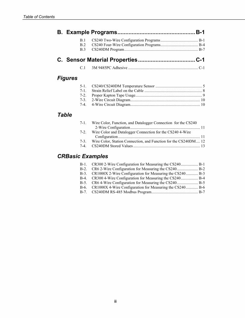
Table of Contents
ii
B. Example Programs ................................................. B-1
B.1 CS240 Two-Wire Configuration Programs ..................................... B-1 B.2 CS240 Four-Wire Configuration Programs ..................................... B-4 B.3 CS240DM Program ......................................................................... B-7
C. Sensor Material Properties .................................... C-1
C.1 3M 9485PC Adhesive ..................................................................... C-1
Figures 5-1. CS240/CS240DM Temperature Sensor .............................................. 5 7-1. Strain Relief Label on the Cable ......................................................... 8 7-2. Proper Kapton Tape Usage .................................................................. 9 7-3. 2-Wire Circuit Diagram..................................................................... 10 7-4. 4-Wire Circuit Diagram..................................................................... 10
Table 7-1. Wire Color, Function, and Datalogger Connection for the CS240
2-Wire Configuration ..................................................................... 11 7-2. Wire Color and Datalogger Connection for the CS240 4-Wire
Configuration ................................................................................. 11 7-3. Wire Color, Station Connection, and Function for the CS240DM .... 12 7-4. CS240DM Stored Values .................................................................. 13
CRBasic Examples B-1. CR300 2-Wire Configuration for Measuring the CS240 ................. B-1 B-2. CR6 2-Wire Configuration for Measuring the CS240 ..................... B-2 B-3. CR1000X 2-Wire Configuration for Measuring the CS240 ............ B-3 B-4. CR300 4-Wire Configuration for Measuring the CS240 ................. B-4 B-5. CR6 4-Wire Configuration for Measuring the CS240 ..................... B-5 B-6. CR1000X 4-Wire Configuration for Measuring the CS240 ............ B-6 B-7. CS240DM RS-485 Modbus Program .............................................. B-7

1
CS240 and CS240DM PT-1000 Class A, Back-of-Module Temperature Sensors 1. Introduction
The CS240 and CS240DM temperature sensors use a precision 1000 ohm class A platinum resistance temperature detector to measure temperature from –40 to 105 °C. They are designed for measuring the back-of-photovoltaic (PV) module temperature but also can be used to measure the surface temperature of other devices. The CS240 can be measured with a 2-wire or 4-wire configuration and is compatible with most Campbell Scientific dataloggers. The CS240DM has a digital RS-485 output that can be directly read by a MeteoPV, CR6, CR1000X, or Modbus RTU RS-485 network. Other Campbell Scientific dataloggers can use an MD485 multidrop interface to read the CS240DM output.
This manual provides information only for CRBasic dataloggers. The CS240 is also compatible with most of our retired Edlog dataloggers. For Edlog datalogger support, contact Campbell Scientific.
2. Precautions • READ AND UNDERSTAND the Safety section at the front of this
manual.
• Do not use epoxy to secure the sensor to a PV module; use Kapton tape.
• Clean the PV module before adhering the sensor to it. The sensor must be adhered to a clean surface for its mounting strip adhesive to function properly.
• If using Kapton tape to secure the disk to the PV module, do not go over the sensor molding with the tape; only put tape over the metal disk portion of the sensor.
• Prying the sensor off will likely damage both the sensor and PV module.
• Proper strain relief of the cable is required after mounting the sensor to the measurement surface (Section 7.2, Mounting/Cable Strain Relief (p. 7)).
• Placement of the cable inside a rugged conduit is advisable for long cable runs, especially in locations subject to digging, mowing, traffic, use of power tools, animals, or lightning strikes.
NOTE

CS240 and CS240DM PT-1000 Class A, Back-of-Module Temperature Sensors
2
3. Initial Inspection • Upon receipt of the sensor, inspect the packaging and contents for damage.
File damage claims with the shipping company.
• The model number, cable length, wiring diagrams, and cable resistance (CS240 only) are printed on a label at the connection end of the cable. Check this information against the shipping documents to ensure the expected product and cable length were received.
4. QuickStart The information provided in this section is for the CS240.
A video that describes datalogger programming using Short Cut is available at: www.campbellsci.com/videos/cr1000x-datalogger-getting-started-program-part-3. Short Cut is an easy way to program your datalogger to measure the CS240 and assign datalogger wiring terminals. Short Cut is available as a download on www.campbellsci.com. It is included in installations of LoggerNet, PC200W, PC400, or RTDAQ.
The following procedure also shows using Short Cut to program the CS240.
1. Open Short Cut and select to create a new program.
2. Double-click the datalogger model.
3. In the Available Sensors and Devices box, type CS240. You can also locate the sensor in the Sensors | Temperature folder. Double-click either CS240 (2-Wire) RTD or CS240 (4-Wire) RTD. If using the 2-wire configuration, type the Cable Resistance. This value is unique for each CS240, and is printed on the heat shrink label attached to the sensor cable. The surface temperature defaults to degree C. This can be changed by clicking the Temperature box and selecting one of the other options. After entering the Properties, click on the Wiring tab to see how the sensor is to be wired to the datalogger.

CS240 and CS240DM PT-1000 Class A, Back-of-Module Temperature Sensors
3
4. Repeat step three for other sensors you want to measure.
5. In Output Setup, type the scan rate, a meaningful table name, and the Data Output Storage Interval.
CS240 and CS240DM PT-1000 Class A, Back-of-Module Temperature Sensors
4
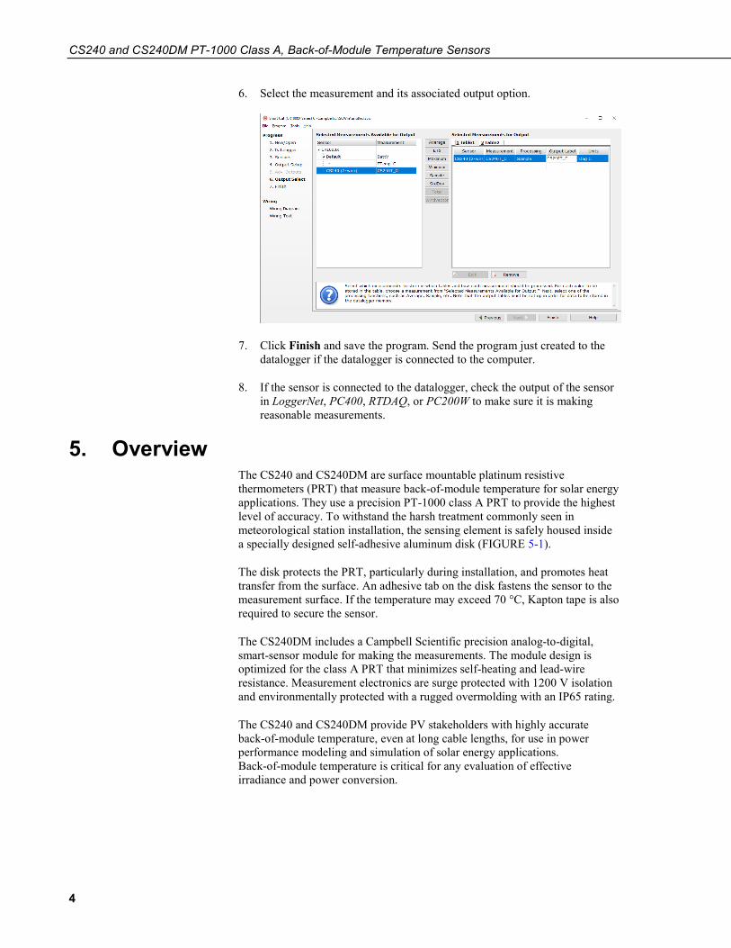
6. Select the measurement and its associated output option.
7. Click Finish and save the program. Send the program just created to the datalogger if the datalogger is connected to the computer.
8. If the sensor is connected to the datalogger, check the output of the sensor in LoggerNet, PC400, RTDAQ, or PC200W to make sure it is making reasonable measurements.
5. Overview The CS240 and CS240DM are surface mountable platinum resistive thermometers (PRT) that measure back-of-module temperature for solar energy applications. They use a precision PT-1000 class A PRT to provide the highest level of accuracy. To withstand the harsh treatment commonly seen in meteorological station installation, the sensing element is safely housed inside a specially designed self-adhesive aluminum disk (FIGURE 5-1).
The disk protects the PRT, particularly during installation, and promotes heat transfer from the surface. An adhesive tab on the disk fastens the sensor to the measurement surface. If the temperature may exceed 70 °C, Kapton tape is also required to secure the sensor.
The CS240DM includes a Campbell Scientific precision analog-to-digital, smart-sensor module for making the measurements. The module design is optimized for the class A PRT that minimizes self-heating and lead-wire resistance. Measurement electronics are surge protected with 1200 V isolation and environmentally protected with a rugged overmolding with an IP65 rating.
The CS240 and CS240DM provide PV stakeholders with highly accurate back-of-module temperature, even at long cable lengths, for use in power performance modeling and simulation of solar energy applications. Back-of-module temperature is critical for any evaluation of effective irradiance and power conversion.

CS240 and CS240DM PT-1000 Class A, Back-of-Module Temperature Sensors
5
FIGURE 5-1. CS240/CS240DM Temperature Sensor
6. Specifications Features:
• Precision PT1000 class A sensing element • Any cable length available—user-selectable and standard lengths
offered • Rugged design holds up in harsh conditions and conduit installations • Self-adhesive backing for easy mounting lasts decades • CS240 has 2-wire or 4-wire configurations to satisfy accuracy even at
long cable lengths • CS240 compatible with Campbell Scientific CRBasic dataloggers:
CR300 series, CR6 series, CR800 series, CR1000, CR1000X series, CR3000, and CR5000
• CS240DM compatible with Campbell Scientific CRBasic dataloggers: CR6 series, CR1000X series, CR300 series (with MD485), CR800 series (with MD485), CR1000 (with MD485), CR3000 (with MD485)
• CS240DM easily interfaces with the MeteoPV Platform without coding
• CS240DM can connect directly with Modbus RTU RS-485 Networks • Calibration services with certification available
Sensor: Precision 1000 ohm class A platinum sensing element
Accuracy: ± (0.15 + 0.002t) °C
Temperature Range: –40 to 135 °C
Temperature Coefficient: TCR = 3850 ppm/K
Long-term Stability: Max Ro drift = 0.04% after 1000 h at 400 °C
Santoprene®-jacketed cable
Overmolded joint
PT1000 class A PRT encased in an aluminum disk

CS240 and CS240DM PT-1000 Class A, Back-of-Module Temperature Sensors
6
CS240 Measuring Current: 0.1 to 0.3 mA
Disk Diameter: 2.54 cm (1.0 in)
Overall Sensor Length: 6.35 cm (2.5 in)
Overmolded Joint Dimensions Width: 1.12 cm (0.44 in) Height: 1.47 cm (0.58 in) Length: 5.72 cm (2.25 in)
Cable Diameter: 0.622 cm (0.245 in)
Disk Material: Anodized aluminum
Weight: 90.7 g (0.2 lb) with 3.2 m (10.5 ft) cable
CS240DM Analog-to-Digital Module: 24-bit Adc A/D Measurement Uncertainty: ±0.015 °C Supply Voltage: 5 to 30 Vdc Power Consumption: 15 mA Surge Protection: 1200 V isolation Environmental Protection: Rugged overmolding with IP65 rating
Approvals: UL AWM 2586 1000V 105 °C; CSA AWM 600V 105 °C FT1
Conforms with Electromagnetic Compatibility Directive (EMC)
Conforms with the Restriction of Hazardous Substances Directive (RoHS2)
Compliance: View EU Declaration of Conformity at www.campbellsci.com/cs240 or www.campbellsci.com/cs240dm
Compliant with IEC 60751, DIN EN 60751, Industrial Design (IEC Class 4) (according to IEC 751)
CS240 Cable Jacket Material: Black semi-gloss PVC, UL VW-1 sunlight
resistant for outdoor use Wire Size and Type: 24 AWG (7/32) tinned copper Nominal Wire Diameter: 0.61 mm (0.024 in) Insulation Type: PVC UL: AWM 10012 1000V 105 °C Filler: Fibrillated polypropylene as required for
uniform round construction. Drain: 24 AWG (7/32) tinned copper (cabled,
touching foil) Shield: Aluminum/mylar (100% coverage, 25%
minimum overlap, foil facing in)

CS240 and CS240DM PT-1000 Class A, Back-of-Module Temperature Sensors
7
CS240DM Cable Features: High flex construction with jacket for
pulling through conduit Jacket Material: Black semi-gloss PVC, UL VW-1 sunlight
resistant for outdoor use; weld spatter and oil resistant
Nominal Wire Diameter: 0.61 mm (0.024 in) Agency Approvals: UL AWM Style 2463 and NEC/CEC
CMX outdoor
7. Installation If you are programming your datalogger with Short Cut, skip Section 7.3, Wiring (p. 9), and Section 7.4, Datalogger Programming (p. 12). Short Cut does this work for you. See Section 4, QuickStart (p. 2), for a Short Cut tutorial.
7.1 Placement on a Photovoltaic (PV) Module The PV module may or may not have distinctive photocells. If the PV module does not have distinctive photocells, center the sensor on the back of the PV module. If the module has several distinctive photocells, center the sensor on the back of the photocell that is the middle of the PV module.
7.2 Mounting/Cable Strain Relief Before mounting, the installers need to wash their hands and then clean the back of the PV module or other device with ethyl alcohol.
7.2.1 Adhesive Mounting Strip The CS240 and CS240DM include an adhesive mounting strip adhered to the flat surface of the aluminum disk. To mount the sensor, remove the paper from the mounting strip and adhere it to the back of the PV module or other device. The mounting strip must be adhered to a clean surface for its adhesive to function properly.
Do not use epoxy to secure the sensor to a PV module.
7.2.2 Kapton Tape Use Kapton tape for cable strain relief; a yellow label on the cable indicates where the cable must be secured (FIGURE 7-1). If the temperature might exceed 70 °C, Kapton tape is also required to better secure the sensor to the measurement surface (FIGURE 7-2).
To ensure that the sensor disk and cable are adequately fastened to the measurement surface, use three strips of Kapton tape in two places each:
1. For strain relief, place the first strip of tape across the cable just below the yellow heat shrink (FIGURE 7-1) and rub the tape surface to remove bubbles.
CAUTION
CAUTION

CS240 and CS240DM PT-1000 Class A, Back-of-Module Temperature Sensors
8
2. Place the other strips of tape on the first strip of tape and rub the tape surface to remove bubbles. These strips of tape should be perpendicular to the first strip of tape—forming an “H” (FIGURE 7-2).
3. To secure the sensor to the module surface, remove the paper from the bottom of the disk and adhere the disk to the PV module (Section 7.1, Placement on a Photovoltaic (PV) Module (p. 7)).
4. Place a strip of tape across the sensor head, perpendicular to the cable and rub the tape surface to remove bubbles. Rub as close as possible to the sensor disk.
Do not go over the sensor molding with the tape; only put tape over the metal disk portion of the sensor.
5. Place the two other strips of tape on the ends of the sensor disk, perpendicular to the first piece of tape and parallel to the cable then rub the tape surface into the module surface (FIGURE 7-2).
FIGURE 7-1. Strain Relief Label on the Cable
CAUTION

CS240 and CS240DM PT-1000 Class A, Back-of-Module Temperature Sensors
9
FIGURE 7-2. Proper Kapton Tape Usage
7.2.3 Strain Relief of CS240DM Analog-to-Digital Module The CS240DM has an analog-to-digital, smart-sensor module incorporated that needs to be secured to the side of PV module. Use two cable tie tabs and cable ties to do this.
7.3 Wiring 7.3.1 Circuit Diagrams
FIGURE 7-3 provides the circuit diagrams for the CS240 2-wire configuration. FIGURE 7-4 provides the circuit diagram for the CS240DM or the CS240 4-wire configuration.

CS240 and CS240DM PT-1000 Class A, Back-of-Module Temperature Sensors
10
FIGURE 7-3. 2-Wire Circuit Diagram
FIGURE 7-4. 4-Wire Circuit Diagram
7.3.2 CS240-to-Datalogger Wiring The dataloggers can measure the CS240 by using a 2-wire or 4-wire configuration (TABLE 7-1 and TABLE 7-2). The 2-wire configuration accuracy decreases, relative to the 4-wire, as a function of the cable length. The 4-wire configuration eliminates resistance due to cable length and is the most accurate way to measure this sensor. The CS240 is shipped ready for the 2-wire configuration. The wires used only for the 4-wire configuration are taped to the side of the cable.

CS240 and CS240DM PT-1000 Class A, Back-of-Module Temperature Sensors
11
TABLE 7-1. Wire Color, Function, and Datalogger Connection for the CS240 2-Wire Configuration
Wire Color Wire Function Datalogger Connection Terminal
Black Voltage excitation input
U configured for voltage excitation1, EX, VX (voltage excitation)
White Analog voltage output
U configured for single-ended analog input1, SE (single-ended, analog input)
Red Reference ⏚ (analog ground) 1U terminals are automatically configured by the measurement instruction.
TABLE 7-2. Wire Color and Datalogger Connection for the CS240 4-Wire Configuration
Wire Color Wire Function Datalogger Connection Terminal
White Analog voltage output1
U configured for differential high analog input2, DIFF H (differential high, analog-
voltage input)
Black Reference1 U configured for differential low analog input2, DIFF L (differential low, analog-
voltage input)
Red Voltage excitation input
U configured for voltage excitation2, EX, VX (voltage excitation)
Red Analog voltage output3
U configured for differential high analog input2, DIFF H (differential high, analog-
voltage input)
White Reference3 U configured for differential low analog input2, DIFF L (differential low, analog-
voltage input)
Black Ground ⏚ (analog ground)
Clear/ Shield Shield ⏚ (analog ground)
1First differential terminal in the BrHalf4W() instruction. 2U terminals are automatically configured by the measurement instruction. 3Second differential terminal in the BrHalf4W() instruction.
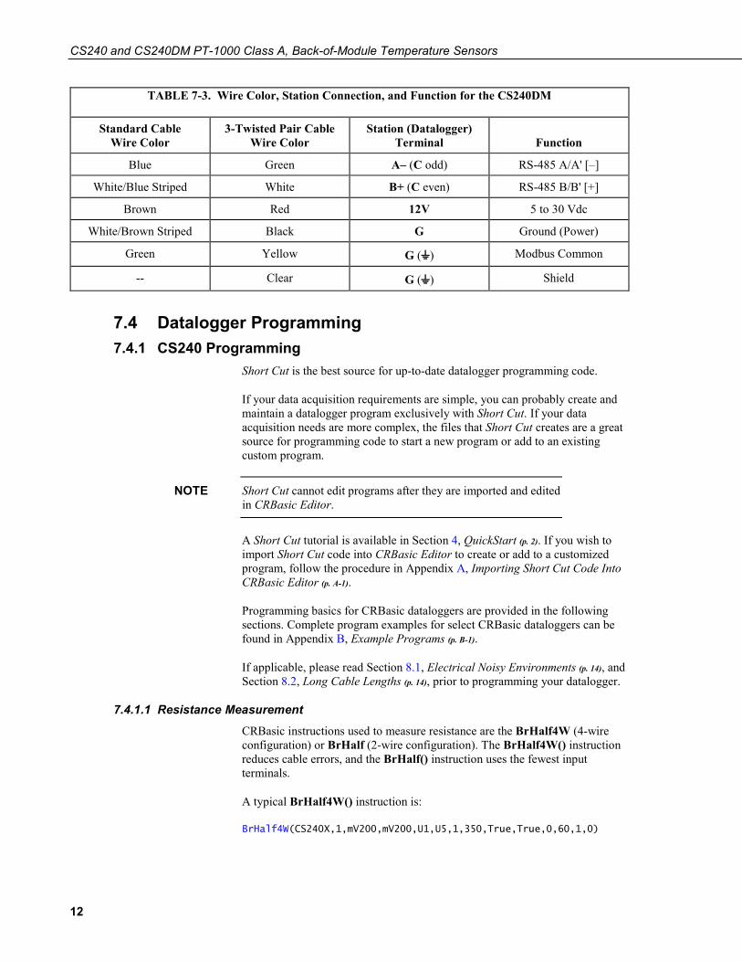
7.3.3 CS240DM Wiring The CS240DM can have a standard cable or a 3-twisted pair cable (TABLE 7-3). The wiring for the CS240DM is also available in the Device Configuration Utility and the MeteoPV User Interface.
CS240 and CS240DM PT-1000 Class A, Back-of-Module Temperature Sensors
12
TABLE 7-3. Wire Color, Station Connection, and Function for the CS240DM
Standard Cable Wire Color
3-Twisted Pair Cable Wire Color
Station (Datalogger) Terminal Function
Blue Green A– (C odd) RS-485 A/A' [–]
White/Blue Striped White B+ (C even) RS-485 B/B' [+]
Brown Red 12V 5 to 30 Vdc
White/Brown Striped Black G Ground (Power)
Green Yellow G (⏚) Modbus Common
-- Clear G (⏚) Shield
7.4 Datalogger Programming 7.4.1 CS240 Programming
Short Cut is the best source for up-to-date datalogger programming code.
If your data acquisition requirements are simple, you can probably create and maintain a datalogger program exclusively with Short Cut. If your data acquisition needs are more complex, the files that Short Cut creates are a great source for programming code to start a new program or add to an existing custom program.
Short Cut cannot edit programs after they are imported and edited in CRBasic Editor.
A Short Cut tutorial is available in Section 4, QuickStart (p. 2). If you wish to import Short Cut code into CRBasic Editor to create or add to a customized program, follow the procedure in Appendix A, Importing Short Cut Code Into CRBasic Editor (p. A-1).
Programming basics for CRBasic dataloggers are provided in the following sections. Complete program examples for select CRBasic dataloggers can be found in Appendix B, Example Programs (p. B-1).
If applicable, please read Section 8.1, Electrical Noisy Environments (p. 14), and Section 8.2, Long Cable Lengths (p. 14), prior to programming your datalogger.
7.4.1.1 Resistance Measurement
CRBasic instructions used to measure resistance are the BrHalf4W (4-wire configuration) or BrHalf (2-wire configuration). The BrHalf4W() instruction reduces cable errors, and the BrHalf() instruction uses the fewest input terminals.
A typical BrHalf4W() instruction is:
BrHalf4W(CS240X,1,mV200,mV200,U1,U5,1,350,True,True,0,60,1,0)
NOTE

CS240 and CS240DM PT-1000 Class A, Back-of-Module Temperature Sensors
13
A typical BrHalf() instruction is:
BrHalf(CS240X,1,mV200,U7,U3,1,350,True,0,60,1,0)
A multiplier of 1.0 and offset of 0.0 should be used in the instructions.
7.4.1.2 Converting Resistance Measurement to Temperature
The PRTCalc() instruction converts the ratio Rs/Ro to temperature, where Rs is the measured resistance of the RTD, and Ro is the resistance of the RTD at 0 degrees Celsius (1000 Ω).
A typical PRTCalc() instruction is:
PRTCalc(CS240T_C,1,CS240Rs/1000,1,1,0)
If the BrHalf instruction (2-wire configuration) was used to measure resistance, the following expression also must precede the PRTCalc instruction:
CS240Rs=CS240X•(1000+Rc)/(1–CS240X)–Rc
Where CS240X is the variable containing the BrHalf measurement and Rc is the cable resistance provided on the cable label.
7.4.2 CS240DM Programming
Programming basics for the CR6 and CR1000X dataloggers are provided in this section. Contact Campbell Scientific if using a datalogger that requires an MD485 interface.
A CR6 or CR1000X datalogger programmed as a Modbus Master can retrieve the values stored in the CS240DM Input Registers (TABLE 7-4). To do this, the CRBasic program requires a SerialOpen() instruction followed by the ModbusMaster() instruction.
TABLE 7-4. CS240DM Stored Values
Value Description
Serial Number Specifies the sensor serial number assigned by the factory
Temperature The CS240DM measures temperature by using a 4-wire configuration. The stored value is in degrees Celsius.
Counter The counter provides an indicator that the sensor is actively taking measurements. This value will increment once per measurement, rolling over at 10,000.
Sensor Status Value State 0 Good 1 Open/Short
Temperature Range Check
Value State 0 Good/In Range 1 Out of Range
NOTE

CS240 and CS240DM PT-1000 Class A, Back-of-Module Temperature Sensors
14
The SerialOpen instruction has the following syntax:
SerialOpen (ComPort, Baud, Format, TXDelay, BufferSize, Mode )
The Format is typically set to logic 1 low; even parity, one stop bit, 8 data bits. The Mode parameter should configure the ComPort as RS-485 half-duplex, transparent.
The ModbusMaster() instruction has the following syntax:
ModbusMaster (Result,ComPort,Baud,Addr,Function, Variable, Start, Length, Tries, TimeOut, [ModbusOption] )
The Addr parameter must match the CS240DM Modbus address. Each Modbus address must be unique on a Modbus network. The default value for the Modbus address is the last two digits of the sensor serial number, with exceptions for serial numbers ending in 00 and 01. These exceptions default to Modbus addresses of 110 and 111, respectively. To collect all of the CS240DM values, the Start parameter needs to be 1 and the Length parameter needs to be 5. ModbusOption is an optional parameter described in the CRBasic Editor Help.
For more information, refer to Appendix B.3, CS240DM Program (p. B-7).
8. Operation 8.1 Electrical Noisy Environments
AC power lines, pumps, power inverters, and motors can be the source of electrical noise. If the CS240 sensor or datalogger is located in an electrically noisy environment, the CS240 sensor should be measured with the 60 or 50 Hz rejection option.
8.2 Long Cable Lengths Placement of the cable inside a rugged conduit is advisable for cable runs over 15 feet, especially in locations subject to digging, mowing, traffic, power tools, animals, or lightning strikes.
8.2.1 CS240 Cable Resistance/Long Cable Lengths Cable resistance can cause significant error. The 4-wire configuration is the best configuration for long cable lengths.
The heat shrink label on the CS240 cable provides the cable resistance (ohms). When using the 2-wire configuration, subtract this cable resistance from the measured resistance value. The value included on the label is calculated with the following equation:
Cable resistance = 0.0274 ohms • cable length (in feet)
Additional settling time may be required for cable lengths longer than 300 feet, where settling time is the delay before the measurement is made. The 60 and 50 Hz integration options include a 3 ms settling time; longer settling times can be typed into the Settling Time parameter in the BrHalf4W() or BrHalf() instruction.

CS240 and CS240DM PT-1000 Class A, Back-of-Module Temperature Sensors
15
8.2.2 CS240DM Long Cable Lengths Digital data transfer eliminates offset errors due to cable lengths. However, digital communications can break down when cables are too long, resulting in either no response from the sensor or corrupted readings. Maximum cable lengths depend on the number of sensors connected, the type of cable used, and the environment of the application. Follow these guidelines when using long cables:
• Use low capacitance, low resistance, screened cable (as fitted by Campbell Scientific) to reach distances of several hundred meters.
• Ensure that the power ground cable has low resistance and is connected to the same ground reference as the datalogger control terminals.
• Be aware that daisy-chaining sensors reduces the maximum cable length roughly in proportion to the number of sensors connected in parallel.
8.3 CS240DM and Device Configuration Utility Device Configuration Utility (DevConfig) is bundled in Campbell Scientific’s datalogger support software and can also be acquired, at no cost, from www.campbellsci.com/downloads. DevConfig can be used to change the CS240DM settings, view stored values, and update the CS240DM operating system (OS). It also provides CS240DM wiring information.
To use DevConfig, the CS240DM must be connected to a computer and 12 Vdc power source. A USB-to-RS-485 adapter is required to connect the CS240DM to the computer. The following is the procedure for connecting to DevConfig:
1. Open DevConfig.
2. Under Device Type, click CS240DM.
3. Follow steps listed under Connecting to a CM240DM with a USB to RS-485 adaptor.

CS240 and CS240DM PT-1000 Class A, Back-of-Module Temperature Sensors
16
The settings are changed in the Holding Registers tab. Except for the Modbus Address, the default values are typical for most Modbus systems and therefore rarely need to be changed.
The values stored are shown in the Input Registers tab.
9. Maintenance and Troubleshooting
For all factory repairs, customers must get an RMA number. Customers must also properly fill out a “Declaration of Hazardous Material and Decontamination” form and comply with the requirements specified in it. Refer to the Assistance page at the front of this manual for more information.
9.1 Troubleshooting Symptom: Temperature is NAN, –INF, –9999, –273
Verify wiring of sensor to the datalogger; cross-reference datalogger program or the measurement system wiring diagram.
Symptom: Incorrect Temperature
Check the cable for signs of damage and possible moisture intrusion.
Symptom: Unstable Temperature
Make sure the clear shield or white/green striped wire is connected to datalogger ground, and the datalogger is properly grounded. For the CS240, try using the 60 or 50 Hz integration options and/or increasing the settling time.
9.2 Maintenance The CS240 and CS240DM sensors require minimal maintenance. Periodically check cabling for proper connections, signs of damage, and possible moisture intrusion.
NOTE

A-1
Appendix A. Importing Short Cut Code Into CRBasic Editor
This tutorial shows:
• Importing a Short Cut program into a program editor for additional refinement
• Importing a wiring diagram from Short Cut into the comments of a custom program
Short Cut creates files, which can be imported into CRBasic Editor. Assuming defaults were used when Short Cut was installed, these files reside in the C:\campbellsci\SCWin folder:
• .DEF (wiring and memory usage information) • .CR300 (CR300-series datalogger code) • .CR6 (CR6-series datalogger code) • .CR8 (CR800-series datalogger code) • .CR1 (CR1000 datalogger code) • .CR1X (CR1000X-series datalogger code) • .CR3 (CR3000 datalogger code) • .CR5 (CR5000 datalogger code)
Import Short Cut code and wiring diagram into CRBasic Editor:
1. Create the Short Cut program following the procedure in Section 4, QuickStart (p. 2). Finish the program. On the Advanced tab, click the CRBasic Editor button. The program opens in CRBasic with the name noname.CR_. Provide a name and save the program.
Once the file is edited with CRBasic Editor, Short Cut can no longer be used to edit the datalogger program.
2. The program can now be edited, saved, and sent to the datalogger.
3. Import wiring information to the program by opening the associated .DEF file. By default, it is saved in the c:\campbellsci\SCWin folder. Copy and paste the section beginning with heading “–Wiring for CRXXX–” into the CRBasic program, usually at the head of the file. After pasting, edit the information such that an apostrophe (') begins each line. This character instructs the datalogger compiler to ignore the line when compiling. You can highlight several lines of CRBasic code then right-click and select Comment Block. (This feature is demonstrated at about 5:10 in the CRBasic | Features video.)
NOTE


B-1
Appendix B. Example Programs B.1 CS240 Two-Wire Configuration Programs
CRBasic Example B-1. CR300 2-Wire Configuration for Measuring the CS240
'CR300 Series 'Declare Variables and Units Dim CS240X Dim CS240Rs Public CS240T_C Units CS240T_C=Deg C 'Define Data Tables DataTable(Hourly,True,-1) DataInterval(0,60,Min,10) Sample(1,CS240T_C,FP2) EndTable 'Main Program BeginProg 'Main Scan Scan(5,Sec,1,0) 'CS240 (2-wire) Class A RTD Back of PV Module Temperature Sensor measurement 'CS240T_C' BrHalf(CS240X,1,mV2500,1,Vx1,1,350,True,0,60,1,0) 'Convert ratio to ohms and remove cable resistance CS240Rs=CS240X*(1000+0.274)/(1-CS240X)-0.274 'Calculate temperature from resistance PRTCalc(CS240T_C,1,CS240Rs/1000,1,1,0) 'Call Data Tables and Store Data CallTable Hourly NextScan EndProg

Appendix B. Example Programs
B-2
CRBasic Example B-2. CR6 2-Wire Configuration for Measuring the CS240
'CR6 Series 'Declare Variables and Units Dim CS240X Dim CS240Rs Public CS240T_C Units CS240T_C=Deg C 'Define Data Tables DataTable(Hourly,True,-1) DataInterval(0,60,Min,10) Sample(1,CS240T_C,FP2) EndTable 'Main Program BeginProg 'Main Scan Scan(5,Sec,1,0) 'CS240 (2-wire) Class A RTD Back of PV Module Temperature Sensor measurement 'CS240T_C' BrHalf(CS240X,1,mV200,U2,U1,1,350,True,0,60,1,0) 'Convert ratio to ohms and remove cable resistance CS240Rs=CS240X*(1000+0.274)/(1-CS240X)-0.274 'Calculate temperature from resistance PRTCalc(CS240T_C,1,CS240Rs/1000,1,1,0) 'Call Data Tables and Store Data CallTable Hourly NextScan EndProg

Appendix B. Example Programs
B-3
CRBasic Example B-3. CR1000X 2-Wire Configuration for Measuring the CS240
'CR1000X Series 'Declare Variables and Units Dim CS240X Dim CS240Rs Public CS240T_C Units CS240T_C=Deg C 'Define Data Tables DataTable(Hourly,True,-1) DataInterval(0,60,Min,10) Sample(1,CS240T_C,FP2) EndTable 'Main Program BeginProg 'Main Scan Scan(5,Sec,1,0) 'CS240 (2-wire) Class A RTD Back of PV Module Temperature Sensor measurement 'CS240T_C' BrHalf(CS240X,1,mV200,1,Vx1,1,350,True,0,60,1,0) 'Convert ratio to ohms and remove cable resistance CS240Rs=CS240X*(1000+0.274)/(1-CS240X)-0.274 'Calculate temperature from resistance PRTCalc(CS240T_C,1,CS240Rs/1000,1,1,0) 'Call Data Tables and Store Data CallTable Hourly NextScan EndProg
Appendix B. Example Programs
B-4
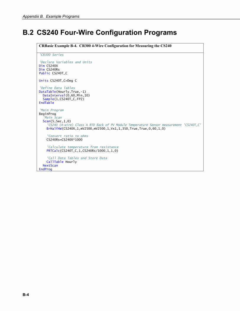
B.2 CS240 Four-Wire Configuration Programs
CRBasic Example B-4. CR300 4-Wire Configuration for Measuring the CS240
'CR300 Series 'Declare Variables and Units Dim CS240X Dim CS240Rs Public CS240T_C Units CS240T_C=Deg C 'Define Data Tables DataTable(Hourly,True,-1) DataInterval(0,60,Min,10) Sample(1,CS240T_C,FP2) EndTable 'Main Program BeginProg 'Main Scan Scan(5,Sec,1,0) 'CS240 (4-wire) Class A RTD Back of PV Module Temperature Sensor measurement 'CS240T_C' BrHalf4W(CS240X,1,mV2500,mV2500,1,Vx1,1,350,True,True,0,60,1,0) 'Convert ratio to ohms CS240Rs=CS240X*1000 'Calculate temperature from resistance PRTCalc(CS240T_C,1,CS240Rs/1000,1,1,0) 'Call Data Tables and Store Data CallTable Hourly NextScan EndProg
Appendix B. Example Programs
B-5
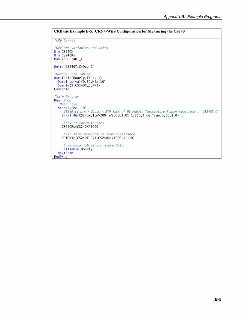
CRBasic Example B-5. CR6 4-Wire Configuration for Measuring the CS240
'CR6 Series 'Declare Variables and Units Dim CS240X Dim CS240Rs Public CS240T_C Units CS240T_C=Deg C 'Define Data Tables DataTable(Hourly,True,-1) DataInterval(0,60,Min,10) Sample(1,CS240T_C,FP2) EndTable 'Main Program BeginProg 'Main Scan Scan(5,Sec,1,0) 'CS240 (4-wire) Class A RTD Back of PV Module Temperature Sensor measurement 'CS240T_C' BrHalf4W(CS240X,1,mV200,mV200,U3,U1,1,350,True,True,0,60,1,0) 'Convert ratio to ohms CS240Rs=CS240X*1000 'Calculate temperature from resistance PRTCalc(CS240T_C,1,CS240Rs/1000,1,1,0) 'Call Data Tables and Store Data CallTable Hourly NextScan EndProg
Appendix B. Example Programs
B-6
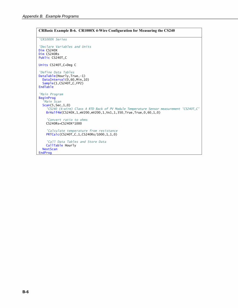
CRBasic Example B-6. CR1000X 4-Wire Configuration for Measuring the CS240
'CR1000X Series 'Declare Variables and Units Dim CS240X Dim CS240Rs Public CS240T_C Units CS240T_C=Deg C 'Define Data Tables DataTable(Hourly,True,-1) DataInterval(0,60,Min,10) Sample(1,CS240T_C,FP2) EndTable 'Main Program BeginProg 'Main Scan Scan(5,Sec,1,0) 'CS240 (4-wire) Class A RTD Back of PV Module Temperature Sensor measurement 'CS240T_C' BrHalf4W(CS240X,1,mV200,mV200,1,Vx1,1,350,True,True,0,60,1,0) 'Convert ratio to ohms CS240Rs=CS240X*1000 'Calculate temperature from resistance PRTCalc(CS240T_C,1,CS240Rs/1000,1,1,0) 'Call Data Tables and Store Data CallTable Hourly NextScan EndProg

Appendix B. Example Programs
B-7
B.3 CS240DM Program
CRBasic Example B-7. CS240DM RS-485 Modbus Program
'CR6 Series Datalogger Public PTemp Public batt_volt Public ResultCode(4) Public CS240DM(20) Public AveTemp(4) Public SD_Temp Public AvgTemp Alias ResultCode(1) = CS240DM_1_ResultCode Alias ResultCode(2) = CS240DM_2_ResultCode Alias ResultCode(3) = CS240DM_3_ResultCode Alias ResultCode(4) = CS240DM_4_ResultCode Alias CS240DM(1) = CS240DM_1_SN Alias CS240DM(2) = CS240DM_1_Temperature Alias CS240DM(3) = CS240DM_1_Counter Alias CS240DM(4) = CS240DM_1_SensorStatus Alias CS240DM(5) = CS240DM_1_RangeCheck Alias CS240DM(6) = CS240DM_2_SN Alias CS240DM(7) = CS240DM_2_Temperature Alias CS240DM(8) = CS240DM_2_Counter Alias CS240DM(9) = CS240DM_2_SensorStatus Alias CS240DM(10) = CS240DM_2_RangeCheck Alias CS240DM(11) = CS240DM_3_SN Alias CS240DM(12) = CS240DM_3_Temperature Alias CS240DM(13) = CS240DM_3_Counter Alias CS240DM(14) = CS240DM_3_SensorStatusk Alias CS240DM(15) = CS240DM_3_RangeCheck Alias CS240DM(16) = CS240DM_4_SN Alias CS240DM(17) = CS240DM_4_Temperature Alias CS240DM(18) = CS240DM_4_Counter Alias CS240DM(19) = CS240DM_4_SensorStatus Alias CS240DM(20) = CS240DM_4_RangeCheck DataTable (Hourly,1,-1) DataInterval (0,60,min,10) Sample (20,CS240DM(),IEEE4) Sample (1,AvgTemp,IEEE4) Sample (1,SD_Temp,IEEE4) EndTable BeginProg SerialOpen (ComC1,19200,2,0,50,4) Scan (1,Sec,0,0) PanelTemp (PTemp,15000) Battery (batt_volt) ModbusMaster (ResultCode(1),ComC1,19200,111,4,CS240DM(1),1,5,3,100,2) ModbusMaster (ResultCode(2),ComC1,19200,2,4,CS240DM(6),1,5,3,100,2) ModbusMaster (ResultCode(3),ComC1,19200,3,4,CS240DM(11),1,5,3,100,2) ModbusMaster (ResultCode(4),ComC1,19200,4,4,CS240DM(16),1,5,3,100,2) AveTemp(1) = CS240DM(2) AveTemp(2) = CS240DM(7) AveTemp(3) = CS240DM(12) AveTemp(4) = CS240DM(17) AvgTemp = (AveTemp(1) + AveTemp(2) + AveTemp(3) + AveTemp(4))/4

Appendix B. Example Programs
B-8
StdDevSpa (SD_Temp,4,AveTemp()) CallTable Hourly NextScan EndProg

C-1
Appendix C. Sensor Material Properties The sensor consists of 6061 aluminum (clear anodized), RTD, 3M9485PC adhesive, and Santoprene® jacketed cable.
C.1 3M 9485PC Adhesive Humidity Resistance: High humidity has a minimal effect on adhesive performance. Bond strengths are generally higher after exposure for 7 days at 90 °F (32 °C) and 90% relative humidity.
U.V. Resistance: When properly applied, nameplates and decorative trim parts are not adversely affected by outdoor exposure.
Water Resistance: Immersion in water has no appreciable effect on the bond strength. After 100 hours in room temperature water, the bond actually shows an increase in strength.
Temperature Cycling Resistance: Bond strength generally increases after cycling four times through:
• 4 hours at 158 °F (70 °C) • 4 hours at –20 °F (–29 °C) • 16 hours at room temperature
Chemical Resistance: When properly applied, adhesive will hold securely after exposure to numerous chemicals including gasoline, oil, Freon™ TF, sodium chloride solution, mild acids, and alkalis.
Heat Resistance: Adhesive is usable for short periods (minutes, hours) at temperatures up to 350 °F (177 °C) and for intermittent longer periods (days, weeks) up to 250 °F (121 °C).
Low Temperature Service: –40 °F (–40 °C). Parts should be tested for low temperature shock service.


Campbell Scientific Worldwide Offices
Australia Location: Garbutt, QLD Australia Email: [email protected]
Website: www.campbellsci.com.au
Germany Location: Bremen, Germany Email: [email protected]
Website: www.campbellsci.de
Brazil Location: São Paulo, SP Brazil
Email: [email protected] Website: www.campbellsci.com.br
South Africa Location: Stellenbosch, South Africa
Email: [email protected] Website: www.campbellscientific.co.za
Canada Location: Edmonton, AB Canada
Email: [email protected] Website: www.campbellsci.ca
Southeast Asia Location: Bangkok, Thailand Email: [email protected]
Website: www.campbellsci.asia
China Location: Beijing, P. R. China
Email: [email protected] Website: www.campbellsci.com.cn
Spain Location: Barcelona, Spain Email: [email protected]
Website: www.campbellsci.es
Costa Rica Location: San José, Costa Rica
Email: [email protected] Website: www.campbellsci.cc
UK Location: Shepshed, Loughborough, UK
Email: [email protected] Website: www.campbellsci.co.uk
France Location: Antony, France
Email: [email protected] Website: www.campbellsci.fr
USA Location: Logan, UT USA
Email: [email protected] Website: www.campbellsci.com
Please visit www.campbellsci.com/contact to obtain contact information for your local US or international representative.