Embed Size (px)
Citation preview
CS211 Lecture: Distributed Systems; Remote Method Invocation; Deployment Diagrams in UML
Last revised October 23, 2006
Objectives:1. To introduce the notion of distributed systems, including the use of deployment
diagrams2. To introduce the client/server and three-layer architecture models3. To introduce the facilities in java.net.4. To introduce the facilities in java.rmi
Materials:1. Projectables from UML User Manual pp. 412, 414, 4152. Executable code and handout of datagram demo implemented with C++ sender
on jonah (datagramdemo.cc and datagramdemo) and Java receiver (DatagramDemo.java).
3. Handout of excerpts from code for CS112 Encryption lab.4. Projectable of “before” and “after” deployment diagrams for converting
registration system to RMI. 5. Demonstration of RegistrationLabs reimplemented as a client/server system
using java.rmi facilities (Run server on jonah, client on laptop; project both on laptop).
I. Introduction
A. In our discussion of threads, we introduced the idea of breaking up a computation being done on a single system into multiple concurrent threads that execute in parallel on the same computer. We now pursue that idea further to consider distributed systems - systems in which computation is spread over multiple physical sites.
1. The term “distributed system” is actually used in both a broad and a narrow sense.
a) In the broad sense, it refers to any system in which computation is spread out over two or more physically distinct processors. The processors may be located in the same room, or may be on opposite sides of the world.
b) In the narrow sense, it refers to what are sometimes called “fully distributed systems” in which information and computation is physically distributed in such a way that even if one physical site fails, the computation can continue - though at reduced speed.
1
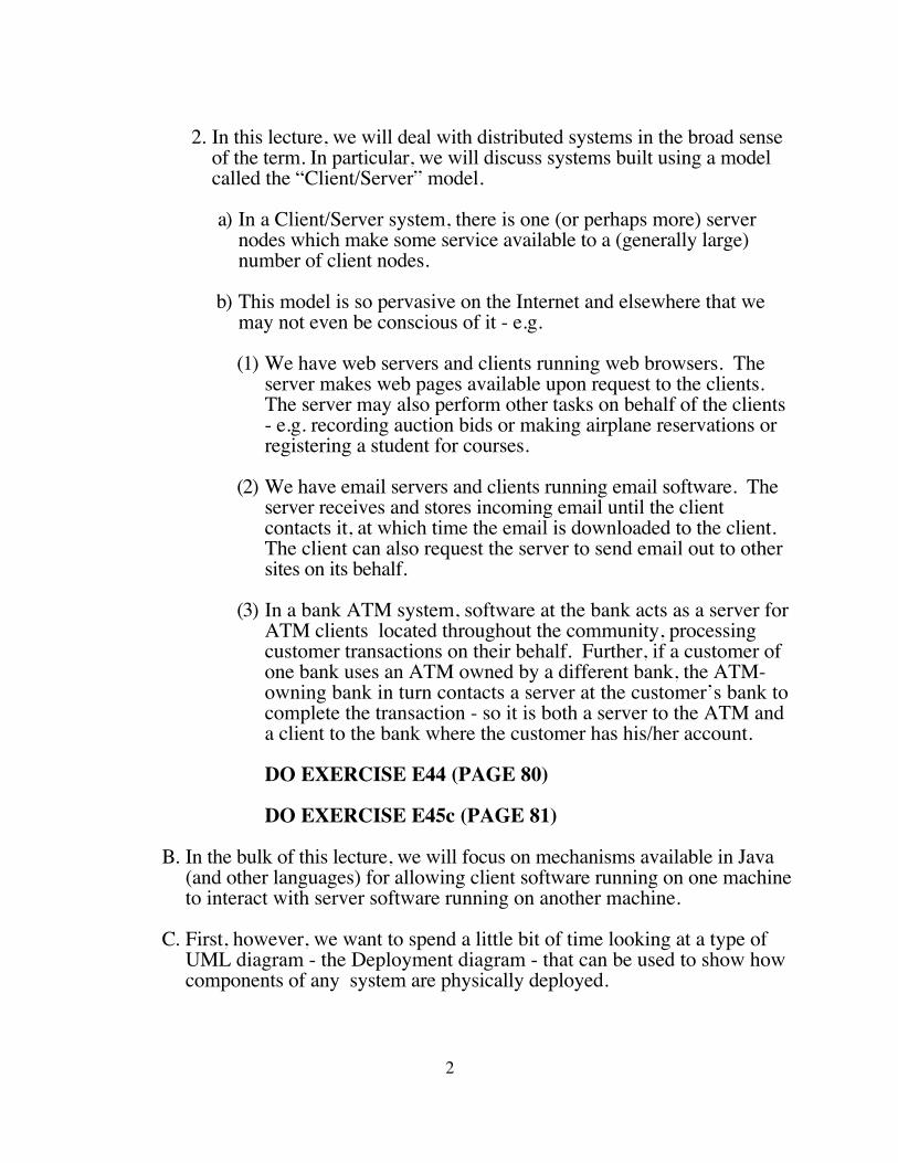
2. In this lecture, we will deal with distributed systems in the broad sense of the term. In particular, we will discuss systems built using a model called the “Client/Server” model.
a) In a Client/Server system, there is one (or perhaps more) server nodes which make some service available to a (generally large) number of client nodes.
b) This model is so pervasive on the Internet and elsewhere that we may not even be conscious of it - e.g.
(1) We have web servers and clients running web browsers. The server makes web pages available upon request to the clients. The server may also perform other tasks on behalf of the clients - e.g. recording auction bids or making airplane reservations or registering a student for courses.
(2) We have email servers and clients running email software. The server receives and stores incoming email until the client contacts it, at which time the email is downloaded to the client. The client can also request the server to send email out to other sites on its behalf.
(3) In a bank ATM system, software at the bank acts as a server for ATM clients located throughout the community, processing customer transactions on their behalf. Further, if a customer of one bank uses an ATM owned by a different bank, the ATM-owning bank in turn contacts a server at the customer’s bank to complete the transaction - so it is both a server to the ATM and a client to the bank where the customer has his/her account.
DO EXERCISE E44 (PAGE 80)
DO EXERCISE E45c (PAGE 81)
B. In the bulk of this lecture, we will focus on mechanisms available in Java (and other languages) for allowing client software running on one machine to interact with server software running on another machine.
C. First, however, we want to spend a little bit of time looking at a type of UML diagram - the Deployment diagram - that can be used to show how components of any system are physically deployed.
2

II. UML Deployment Diagrams
A. The major components of a deployment diagram are nodes - symbols representing either a processor or some significant piece of hardware that the system utilizes.1. The standard symbol for a node is a cube:
2. Nodes representing specialized pieces of hardware can be represented
by specialized symbols, as we shall see shortly.3. Nodes are connected by associations, representing the flow of
information back and forth between them.4. We may also explicitly show the network which allows the nodes to
communicate, if they communicate via a general-purpose network rather than via dedicated hard-wired connections.
5. Note that, in contrast to other diagrams we have drawn, in a Deployment diagram the symbols represent hardware - not software. (The software is deployed on one or more processors, depicted by node symbols.)
B. Deployment diagrams can be used to depict several different types of systems:1. Embedded Systems2. Client/Server Systems3. Fully-Distributed Systems
C. Embedded Systems1. An embedded system is one in which a computer is embedded in some
piece of physical equipment to control it (e.g. a home appliance, a car, or a chemical plant)
2. The following example appears in the UML User Manual, depicting an embedded system controlling an autonomous robotPROJECT: UML User Manual page 412Note that there is only one processor - the remaining nodes are specialized hardware controlled by software in the processor. Note
3
also the used of specialized symbols for these nodes - chosen ad-hoc to help the reader understand the diagram. (These are not standard UML symbols!)
3. We could depict our ATM example system using such a diagram to depict the various specialized pieces of hardware in relationship to the controlling processor that runs the software we have discussed in previous lectures. Note that, in this case, we are depicting hardware - not the software that controls the hardware. (E.g. in previous discussions, we have used a class CardReader to represent the software that controls the physical device that reads ATM cards. In this diagram, that class is part of the software that is deployed on the processor that controls the system, and the card reader symbol stands for the physical hardware device it controls.) ASK FOR A VOLUNTEER TO PRODUCE SUCH A DRAWING ON THE BOARD.
D. Client/Server Systems
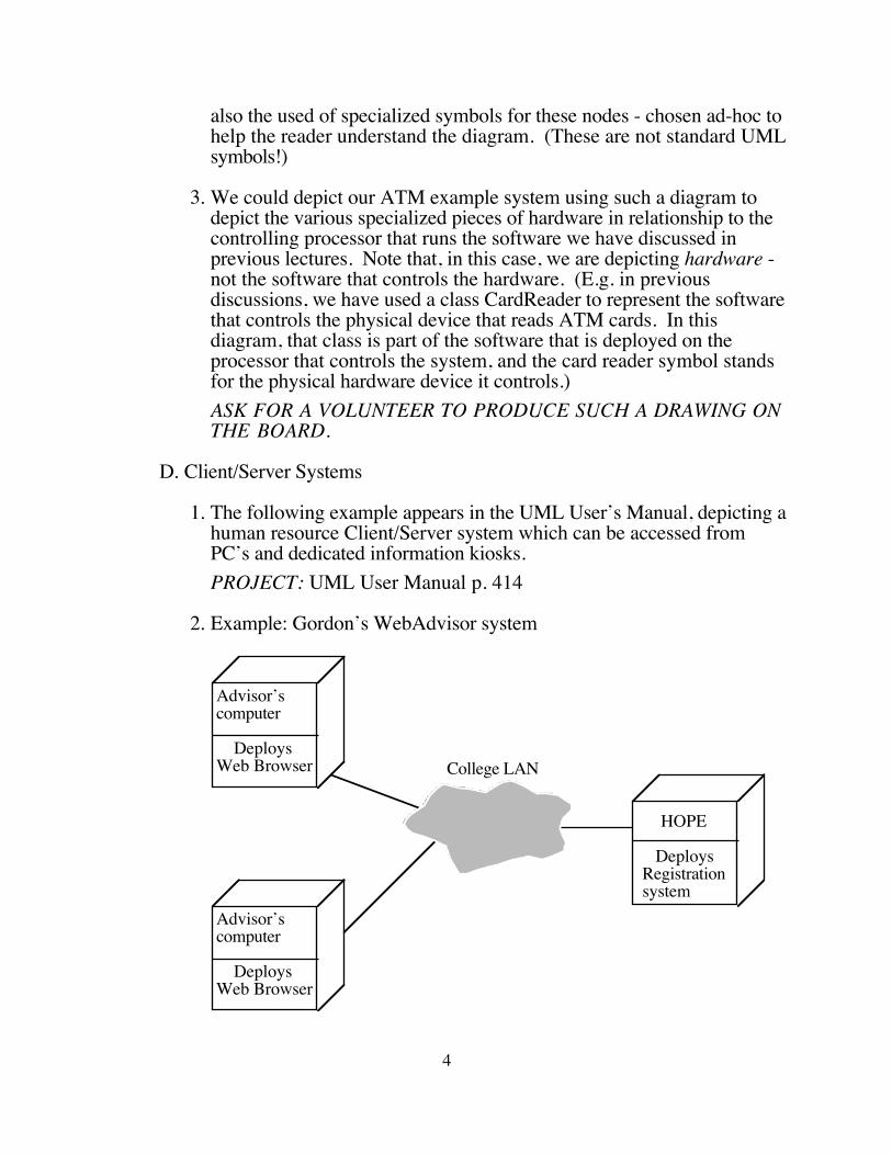
1. The following example appears in the UML User’s Manual, depicting a human resource Client/Server system which can be accessed from PC’s and dedicated information kiosks.PROJECT: UML User Manual p. 414
2. Example: Gordon’s WebAdvisor system
HOPE
DeploysRegistrationsystem
Advisor’scomputer
DeploysWeb Browser
College LAN
Advisor’scomputer
DeploysWeb Browser
4
Note how the network connecting the advisor computers to the registration system is depicted.
3. Example: Our ATM system (viewed now as a node) connected to the bank’s computer.
ASK FOR A VOLUNTEER TO PRODUCE SUCH A DRAWING ON THE BOARD.
E. Fully Distributed Systems
Example: PROJECT - UML User Manual page 415
Note how the Internet is depicted, potentially connecting any console to any regional server, while direct hard-wired connections between specific servers are shown as associations.
F. A Deployment diagram is not required for the VideoStore example system, as specified.
1. The system we have been designing thus far has been designed, presumably (but perhaps unrealistically), to run on a single computer
2. Suppose, however, that we were to design it as a distributed system - perhaps with several clerk consoles (computers), and perhaps some kiosks that customers can use to make inquiries. What might such a system look like?
ASK
DEVELOP A DEPLOYMENT DIAGRAM AS A CLASS.
Some options to consider
a) Server - perhaps a separate system
b) Manager console - perhaps a separate system, or server system could double in this capacity.
3. Note: for purposes of the project, do not attempt a distributed implementation!
5

III. Inter-System Communication
A. We now move from a general consideration of distributed systems to a specific consideration of how participating systems communicate with each other. Since we are using Java in this course, we will deal with mechanisms available to programs written in Java; however, most will be usable with other languages as well.
B. The specific question we want to explore, then, is “how does a program running on one computer go about communicating with a program running on another computer?”1. We assume that the computers are connected via some sort of network
- either a local area network or the Internet. 2. We assume that information is transmitted over the network using
TCP/IP - the basic protocol used by the Internet and many LAN’s. (Certainly other networking protocols can be used; but the mechanisms built into the Java libraries assume TCP/IP)
3. In the Client/Server model, the communication is initiated by a client program wishing to communicate with a server program. However, much of what we say here is applicable to other models as well.
C. There is more than one possible answer to this question. Each possible answer has advantages and disadvantages. 1. A low-level approach: using TCP/IP services directly, through facilities
in the package java.net.a) Advantages - most flexibleb) Disadvantages - makes programmer responsible for managing a lot
of detailsc) We will discuss this approach in some detail later, so that you will
be familiar with it2. Using a technology connected to web pages
a) For example, a technology called CGI is supported by most web servers.(1) In brief, the web server recognizes a URL having a certain
format as being a CGI request, rather than an ordinary page request. (Each type of web server has its own rules for the format of CGI requests).
(2) When the web server receives such a request, it runs a program (whose name is typically specified as part of the request). The request may also specify parameters to be sent to the program.
6
(3) The program creates a web page “on the fly”, which the server then sends to the client as the response to its request.
b) There are numerous similar systems such as “servlets” (little Java programs that can execute inside a server application), Microsoft ASP, php, etc.
c) Advantage - supported by existing web servers and browsers. d) Disadvantage - really designed for this specific purpose. Not a
general-purpose mechanism for letting two programs communicate with each other. (A Java program could “pretend” to be a web browser and could communicate with another program through a web server on the server system, but this is a rather roundabout approach!
e) We will not discuss CGI or similar systems further3. Using an object request broker (ORB).
a) An object request broker is a piece of software that needs to be running on both machines. It allows a client program running on one machine to invoke methods of an object in a program running on a server machine. In effect, once access to a remote object has been established, a client program can interact with the remote object the same way it interacts with a local object - the location is not a factor in how it uses an object. (The remote object looks just like a local object to the program using it.)(1) There is an industry standard for ORBs called CORBA
(Common Object Request Broker Architecture.) (2) Thus, when we talk about using an ORB, we usually mean using
an ORB that complies with the CORBA standards.b) The major advantage of CORBA is that it is a cross-language, cross-
platform industry standard.(1) Because CORBA is an industry standard, CORBA-compliant
ORBs from different software vendors can inter operate with each other just as well as ORBs from the same vendor. Thus, a client and a server do not have to be running the same ORB software.
(2) CORBA is cross platform - Any CORBA-compliant ORB on one machine can communicate with any CORBA-compliant ORB on another machine, regardless of the machine or operating system.
(3) CORBA is cross language - A CORBA-compliant ORB allows a program written in (say) Java to access objects in a program written in (say) Smalltalk on another machine.
7
(a) This is accomplished by specifying the interface to an object using a language-neutral Interface Definition Language (IDL).
(b) A CORBA-compliant ORB includes IDL compilers which translate an IDL specification into appropriate language-specific interfaces and implementation skeletons.
(c) Note that the Java library includes a package org.omg that provides the Java side of the link to a CORBA-compliant ORB on the same computer, which can then be used to link to ORB’s on other computers. (The org.omg package is not an ORB, it provides facilities for using an ORB.)
c) A major disadvantage of CORBA is that it is complex and CORBA-compliant ORBs are fairly expensive.
d) We will not discuss CORBA further.4. Using Microsoft’s .NET framework
a) Microsoft’s .NET framework includes support for distributed applications that replaces an older - now deprecated - Microsoft technology known as DCOM (Distributed Component Object Model)
b) In some respects, .NET was developed to compete with Sun’s Enterprise Edition java, though it can be used with Microsoft’s clone of Java.
c) Although the open source community is developing versions of the .NET framework for non-Microsoft platforms, at this point it is largely a proprietary technology.
d) We will not discuss .NET further5. Using Java RMI (Remote method invocation).
a) RMI provides capabilities similar to those provided by an ORB, but only to Java programs.
b) A major advantage of RMI for us is that it is integrated into the Java language and libraries
c) A major disadvantage of RMI is that it is integrated into the Java language and libraries!
d) We will discuss RMI in some detail later in this lecture, because it is readily available to us. If you understand RMI, you will find it easier to understand approaches like CORBA, because there are significant similarities (though obviously there are important differences as well).
8
IV. Architecture of Client/Server Systems
A. Before turning to a detailed discussion of Java facilities for inter-system communication, it will be useful to spend a bit of time on the overall architecture of client server systems.
B. Though there are many ways to configure such a system, most are based on recognizing three basic kinds of tasks needing to be done:
1. The three kinds of tasks are these:
a) Interface task - e.g. typically providing a GUI for the user.
b) Business logic tasks - e.g. performing the basic processing.
c) Database tasks - e.g. storing the information.These different tasks can be thought of as being the responsibility of different layers in the software.
2. Several of the systems we have worked with previously have actually exhibited a clear distinction between these different tasks and layers.ASK FOR EXAMPLES
a) The Address Book problem we did in CS112 and used for some examples in this course:(1) The AddressBookGUI class performs interface tasks
(2) The AddressBookController class perform business logic tasks
(3) The AddressBook and Person classes perform database tasks
b) The course registration system we used in the Java collections labs:(1) The RegistrationLabsGUI class performs interface tasks.
(2) The controller class performs the business logic tasks.
(3) The RegistrationModel, Course, Student, and EnrolledIn classes perform the database tasks.
3. Note that there is considerable similarity between this division of labor and the three-fold way we classified analysis classes:
9
a) Boundary classes are most often found in the interface layer
b) The heart of the business logic layer is composed of controller classes. But note that controller classes can and do appear in the other layers as well.
c) The heart of the database layer is composed of entity classes. But note that entity classes can and do appear in other layers as well - in fact, the entity classes comprising the database are often used by the other layers, and often appear as parameters and/or return values of the methods in these layers.
C. When a distributed system is designed, there are several general approaches which can be taken as to where these various layers exist:
1. “Thin client” approach - the interface layer resides on the client system, and the business logic and database layers reside on the server system.
a) This makes the server responsible for the bulk of the processing.
b) But this also prevents hackers from altering the rules by tampering with the client software.
c) It may allow the client to something generic like a web browser, so that the client does not need to contain any software specific to the system except for software downloaded when accessing the server (web pages and/or applets).
d) CGI is very much designed to support this model. The other approaches can be used this way as well.
2. “Thick client” approach - the interface and business logic layers both reside on the client, with only the database layer on the server.
a) This reduces the processing burden on the server.
b) But it means that the client must contain significant application-specific software, typically permanently installed, which raises installation and security concerns.
c) java.net, CORBA, .NET and rmi can be used this way. CGI is not really designed for this model, though it could be used this way.
3. It is also possible to use three systems - one running each layer - giving what’s called a three-tier architecture.
10

a) The interface layer runs on client computers.
b) The business logic layer runs on a single server system which the clients contact.
c) The business logic server system, in turn, makes use of a database server system to actually access and modify the data.
d) This approach may arise in the context of a pre-internet system that is extended to support remote access via the Internet.EXAMPLE: Gordon’s WebAdvisor system is actually configured along these lines.
(1) The interface layer is a web browser running on a professor’s computer, using downloaded web pages.
(2) The business layer is partially implemented on a web server system maintained by the college.
(3) The registrar’s database is on another system maintained by the college (which is why it may be possible to register at the registrar’s office but not via WebAdvisor!) Though the vendor has evolved the system over time, Gordon was using this basic software system in 1979, long before the www was invented!
DO EXERCISE E46 c (PAGE 85)
D. We now move to a more detailed discussion of two approaches to building distributed systems: low-level networking using java.net, and RMI.
1. We discuss java.net first because it is the foundation on which the other technologies are built - e.g. in a system written in Java that uses CGI, CORBA, DCOM, or RMI, these facilities would be implemented on top of the networking facilities of java.net (though usually in a way that the user does not have to be directly aware of it.). The java.net facilities can be used to cooperate with programs written in many different languages, not just Java.
2. We discuss RMI because it is a much cleaner, higher-level facility, and understanding it will help with subsequent understanding of mechanisms such as CORBA or DCOM. Note, however, that RMI requires that both communicating programs be written in Java.
11
V. Low-Level Networking: Using the java.net Package
A. The java.net package contains classes that allow a Java programs on one machine to communicate with another program on another machine using industry-standard TCP/IP protocols. (Note that the other program does not have to be written in Java.)
B. Our goal is not to cover this package in depth, but rather to give something of the flavor of what’s involved when programs communicate at this level - if nothing else, to motivate the more abstract approaches!
C. TCP/IP networking defines several different models of communication, of which two are particularly important
1. Connectionless communication using datagrams. (This is technically called UDP - the user datagram protocol).
a) In this model, a machine can send a message to another system (called a datagram) without first establishing a connection with that machine.
b) The network makes a good faith effort to deliver the message correctly, but there is no guarantee that the message will not be lost in transit, corrupted, or even delivered twice!
c) Further, if one machine sends several datagrams to another machine, there is no guarantee that the datagrams will arrive in the same order in which they were sent.
d) If the receiving machine wishes to reply, it may send a message back to the first machine. But this is treated as a separate message in its own right.
2. Connection-oriented communication using streams. (This is technically called TCP - transmission control protocol. Note that, in the acronym TCP/IP, IP stands for the underlying network protocol and TCP for the commonly-used stream protocol built on top of it. UDP is actually an alternative to TCP, also built on IP.)
a) In this model, a client first establishes a connection to a server.
b) While the connection remains open (i.e. until either machine closes it), either machine may send messages to the other machine.
c) The network guarantees correct, accurate delivery of the messages.
12
d) Further, if one machine sends several messages to another machine, they are guaranteed to appear to arrive in the same order as they were sent. (A “later” message that arrives before an “earlier” one is held by the TCP software at the receiving end until the “earlier” one arrives.)
e) The receiving machine can reply to a message over the same connection on which it was sent.
3. There are significant analogies between these two models and more familiar communication mechanisms:
a) Connectionless networking using datagrams is similar to postal mail. When you mail a letter to another person, the Postal Service makes a good-faith effort to deliver it intact. However, there is no guarantee that the letter will not be lost or damaged in transit, and if you send several letters to the same destination they may arrive in a different order than the order in which you sent them. (One thing that the US Postal Service cannot do that the network can is to duplicate messages!).
b) Connection-based networking streams is similar to the use of a telephone. Before you can communicate with someone else via telephone, you must first establish a connection by placing a call and having it answered. Absent serious problems with the phone system, what you say is heard accurately and completely by the other person, and in the order in which you say it. The other person can reply to you over the same connection. (The network improves on the phone system in that, if there are problems with the network, the message will still get through in the proper sequence - but maybe after some delay.)
c) At the implementation level, connection-based networking is actually implemented by using the datagram mechanism to transmit information and acknowledgments that ensure that message delivery is done reliably.
D. A fundamental notion in IP networking is the notion of a socket. A socket is an endpoint for communication between two systems.
1. Datagram sockets are used for UDP communication
a) Rather than go into a lot of detail regarding datagram sockets, we’ll look at a simple example.
13
b) To illustrate the language-independent nature of IP networking, we will use a program written in C++ on one machine to send a message to another program written in Java on another machine, which will simply display the message, along with information about where it came from.
(1) DEMO: datagramdemo.cc (client) on jonah; DatagramDemo.java (server) on laptop. (Use port 4242)
• First demo with no one listening - note message is ignored
• Then demo with server listening
(2) HANDOUT: Code excerpts
2. Stream sockets are used for TCP communication
a) In this protocol, a connection is established involving a socket on one system and a socket on another system. A stream of bytes written into one socket can be read from the other socket, and vice versa. (A pair of sockets supports two-way communication).
(1) A “tin can telephone” of the type you may have used as a kid is a good model for a pair of connected sockets.
(2) Note that sockets support communication at the level of streams of bytes. More complex data (numbers, objects, etc) must be reduced down to a stream of bytes in order to be sent, and must be converted back to the appropriate type of entity at the other end. This process is known as “marshaling” and “unmarshaling”.
b) TCP/IP incorporates the notion of a “server socket”, which is a special kind of socket that waits for connection requests from another system.
(1) When an appropriate connection request is received, a socket is created on each system, and the two sockets are connected to each other.
(2) The only role of the server socket is to initiate the connection; the same server socket can be used to initiate any number of connections.)
14
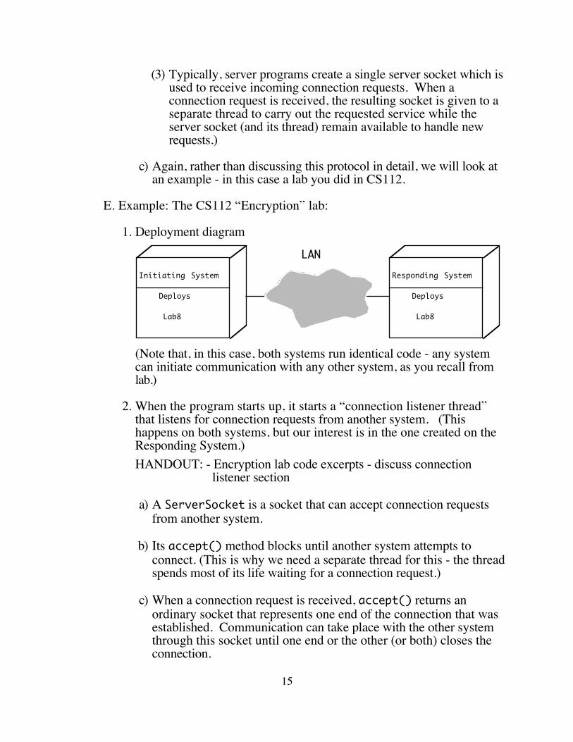
(3) Typically, server programs create a single server socket which is used to receive incoming connection requests. When a connection request is received, the resulting socket is given to a separate thread to carry out the requested service while the server socket (and its thread) remain available to handle new requests.)
c) Again, rather than discussing this protocol in detail, we will look at an example - in this case a lab you did in CS112.
E. Example: The CS112 “Encryption” lab:
1. Deployment diagram
Initiating System
Deploys
Lab8
LANResponding System
Deploys
Lab8
(Note that, in this case, both systems run identical code - any system can initiate communication with any other system, as you recall from lab.)
2. When the program starts up, it starts a “connection listener thread” that listens for connection requests from another system. (This happens on both systems, but our interest is in the one created on the Responding System.)HANDOUT: - Encryption lab code excerpts - discuss connection
listener section
a) A ServerSocket is a socket that can accept connection requests from another system.
b) Its accept() method blocks until another system attempts to connect. (This is why we need a separate thread for this - the thread spends most of its life waiting for a connection request.)
c) When a connection request is received, accept() returns an ordinary socket that represents one end of the connection that was established. Communication can take place with the other system through this socket until one end or the other (or both) closes the connection.
15
3. Meanwhile, on the Initiating System, clicking the “Send” button causes a SendDialog box to be created. When the dialog is all filled in and the user requests that a message be sent, the following code is executed:HANDOUT - message send section
a) The form of the Socket constructor used in this code attempts to establish a connection at the specified address, on the specified port.)
b) If a connection is established, the Socket thus created becomes one end of the pair of connecting sockets that can be used for communication. (If a connection cannot be established, an exception is thrown.)
c) We now create a PrintWriter object from this socket (using a wrapper). What is printed into the print writer will be transmitted over the network to the corresponding socket on the other end.
d) Note that, in this case, we send a single line of data before closing the socket and terminating the connection shortly after establishing it. We could just as easily send many lines of data over an extended period of time if we wished.
4. Back on the Responding System, we have seen that, when a connection request arrives, a new ordinary socket is created, a ReceiveDialog box is created to display the message, and a new thread is created. This thread actually receives the message and displays it in the dialog. (A separate thread is created for this purpose, so the listener thread can go back to listening for other connections.)HANDOUT: Code for receiving message
a) connectionSocket is the socket that was created when the connection request was accepted.
b) Note how this is “wrapped” in a BufferedReader that allows us to read line(s) of input sent by the sender.
c) In this case, we know only one line will be sent, so we close the socket after reading the single line - but we could leave it open and receive additional lines if that were the protocol.
16
VI. Using RMI
A. A significant limitation of low-level networking using the facilities of java.net is that the communicating programs must assume full responsibility for managing the details of marshaling and unmarshaling parameters to requests. RMI provides a much higher level approach. It is based on an earlier technology developed by Sun called remote procedure call (RPC) which has been used with many programming languages. In effect, RMI is the Java version of RPC.
B. When using RMI, the basic idea is that a program is allowed to work with two kinds of objects: local objects (which exist inside of the memory of the machine that is running the program) and remote objects (which exist in the memory of some other machine.) However, this distinction is made transparent to the program, as follows:
1. If the program executes a method of a local object, that method is performed by the system running the program.
2. If the program executes a method of a remote object, the rmi system creates a message which is sent over the network to the system where the object really “lives”. That system then executes the method and sends a message back with any results (return value.) The messages are sent/received automatically, transparently to the program which references remote objects in the same way it references local objects.
3. The initial setup to use RMI in a program is a bit complex, but once it is set up, the program author can proceed without further consciousness of it. We will first consider what needs to be done as the software is being developed, and then what needs to happen when it is run.
C. What needs to be done during software development
1. Identify remote classes - i.e. classes whose objects will “live” on the server side, but whose methods may be invoked on the client side.
2. For each such class, it is necessary to define an interface that spells out what methods the class makes available remotely. (The class may define some methods that are only available locally; these are omitted from the interface.)
a) The interface must be made a sub-interface of java.rmi.Remote
17
b) Each method in the interface must be declared as being capable of throwing java.rmi.RemoteException. (This class of exception represents exceptions that can arise as a direct consequence of using an object remotely - e.g. various sorts of communication problems that can happen on a network.)
c) On the client side, remote objects will be instances of this interface.
d) When the client calls methods of a remote interface, it must include appropriate code for dealing with the possibility of a RemoteException (the one place where the client code needs to differ for a remote object as opposed to a local object.)
3. It is also necessary to define a concrete class that implements the interface.
a) On the server side, objects that can be accessed remotely will be instances of this class.
b) Typically, the implementation class is made a subclass of java.rmi.server.UnicastRemoteObject. This class provides some facilities needed by remote objects which they inherit by being a subclass of it.
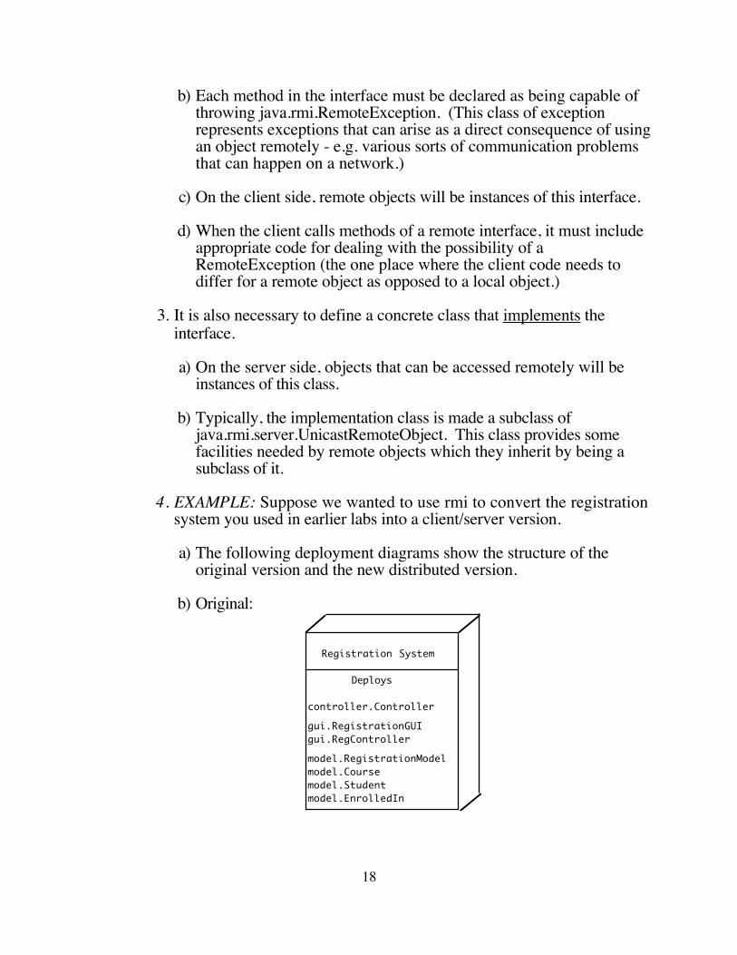
4. EXAMPLE: Suppose we wanted to use rmi to convert the registration system you used in earlier labs into a client/server version.
a) The following deployment diagrams show the structure of the original version and the new distributed version.
b) Original:
Registration System
Deploys
controller.Controller
gui.RegistrationGUIgui.RegController
model.RegistrationModelmodel.Coursemodel.Studentmodel.EnrolledIn
18
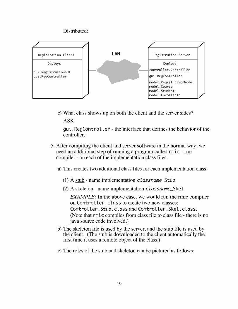
Distributed:
c) What class shows up on both the client and the server sides?ASKgui.RegController - the interface that defines the behavior of the controller.
5. After compiling the client and server software in the normal way, we need an additional step of running a program called rmic - rmi compiler - on each of the implementation class files.
a) This creates two additional class files for each implementation class:
(1) A stub - name implementation classname_Stub(2) A skeleton - name implementation classname_Skel
EXAMPLE: In the above case, we would run the rmic compiler on Controller.class to create two new classes: Controller_Stub.class and Controller_Skel.class. (Note that rmic compiles from class file to class file - there is no java source code involved.)
b) The skeleton file is used by the server, and the stub file is used by the client. (The stub is downloaded to the client automatically the first time it uses a remote object of the class.)
c) The roles of the stub and skeleton can be pictured as follows:
19
LAN Registration Client
Deploys
gui.RegistrationGUIgui.RegController
Registration Server
Deploys
controller.Controller
gui.RegController
model.RegistrationModelmodel.Coursemodel.Studentmodel.EnrolledIn

D. What needs to happen when the program is run.1. Before running any rmi server program, it is necessary to run a
program on the server called rmiregistry. This program manages the task of establishing initial access to a remote object.
2. When the server program starts up, it must include a call to a method called Naming.bind(name, object) or Naming.rebind(name, object) which places a reference to a remote object in the registry.
3. When a client program starts up, it must include a call to a method called Naming.lookup(url), which accesses the remote object by invoking the registry on the server where it resides.
20
Local clientobject(s)
Local serverobject(s)
CLIENT SYSTEM SERVER SYSTEM
Remoteobject
result := operation()
Local clientobject(s)
Local serverobject(s)
Remoteobject
result := operation()
Stub object Skeleton object
APPARENT SITUATION
ACTUAL SITUATION

E. DEMO: The RMI version of the registration system
1. The Server will run on a workstation
a) cd cs211/RMIExample/RMIExampleServer/build/classes
b) CLASSPATH= [ Needed due to db2 issues ]
c) rmiregistry &
d) cd ../..
e) java -cp build/classes controller.Controller
2. The client will run on laptop: DEMO
a) cd RMIExample/RMIExampleClient
b) java -cp build/classes RegistrationLabsGUI micah.cs.gordon.edu
F. One thing that is missing from the our discussion thus far is (and is not present in the version of the code we are using) is synchronization.
1. Each time the rmi registry is contacted by a client, it creates a separate thread.
2. Thus, if our GUI is running on two or more different systems accessing the same server, two different threads could perform conflicting operations at the same time.
3. This should be handled by explicit synchronization in the server code. How should this be done, and where should it go?ASKEach of the methods that alters the database (doEnroll(), doDrop(), doGrade()) needs to be synchronized. Since they all share the same controller object, this will ensure that two threads don’t perform an operation that alters the database at the same time.
21