Embed Size (px)
DESCRIPTION
CS0316-2_N_doc_CS0316-2_N
Citation preview

CONDICIONES DE SUMINISTRO
SUPPLY CONDITIONS
Doc.: CS0316-2
Rev.: N
INSTALACIÓN ELÉCTRICA Y ELEMENTOS ESPECÍFICOS TORRE ACERO AW3000
ELECTRIC INSTALLATION AND SPECIFIC ELEMENTS AW3000 STEEL TOWER P. 1 / 25
Rev Fecha Date
Descripción de la revisión Description of the revision
“A” 10.02.11 Elaboración // First edition
“M” 02.04.14 Eliminada escalera central tramo superior / Upper section central ladder removed
“N” 16.09.14 Modificar esquema conexión luminarias (pto 5.2) / Modify light conection diagram (point 5.2)
“Ñ”
Realizado / Done Revisado / Reviewed Aprobado / Approved
En caso de duda prevalecerá la versión en castellano/ In case of doubt, the Spanish version shall prevail. © 2014 ACCIONA WINDPOWER S.A. Todos los derechos reservados / All rights reserved
1. OBJETO
El objeto del presente cuaderno de especificaciones es describir los requisitos que debe cumplir la fabricación de las torres, teniendo en cuenta la instalación eléctrica así como de los puntos particulares de las máquinas de Acciona Windpower. Para poder suministrar estas piezas tanto en fase prototipo como en serie, las siguientes disposiciones deben cumplirse en su totalidad, salvo acuerdo puntual otorgado al proveedor.
2. NORMATIVA APLICABLE
UNE EN 10204 Productos metálicos. Tipos de documentos de inspección.
3. ETIQUETADO DE CABLES El etiquetado de los cables se realizará con etiquetas embridadas al cable tal y como se muestra en la figura 1. La etiqueta será negra con los números y letras individuales. Los códigos serán los indicados para cada cable en los diferentes apartados de esta condición de suministro y serán colocados en ambos extremos de estos. Esta identificación es complementaria a
1. AIM
This manual contains the specifications of the towers, taking into account the electric installation as well as the points specific to Acciona Windpower turbines.
The following applies to these items both in the prototype as well as the final product, except when the supplier is granted specific authorization.
2. APPLICABLE STANDARDS
UNE EN 10204 Metallic products. Types of inspection documents
3. LABELLING THE WIRES Wires shall be labelled with tags tied to the wire as shown in figure 1. The tag will be black with individual letters and numbers. The codes for each cable are in the various sections of this supply condition and will be placed at both ends of the cable. This identification is complementary to
16-09-2014 17-09-2014 17-09-2014

CONDICIONES DE SUMINISTRO
SUPPLY CONDITIONS
Doc.: CS0316-2
Rev.: N
INSTALACIÓN ELÉCTRICA Y ELEMENTOS ESPECÍFICOS TORRE ACERO AW3000
ELECTRIC INSTALLATION AND SPECIFIC ELEMENTS AW3000 STEEL TOWER P. 2 / 25
la identificación por colores de los cables de rotor y estator.
the colour identification of the rotor and stator wires.
Figura 1. Etiqueta identificación cables/ Figure 1. Wire identification tag
4. CABLEADO DE POTENCIA 4. POWER CABLING Los cables que lleguen en carretes, deberán ser almacenados y manipulados correctamente como se muestra en las siguientes imágenes de ejemplo para no dañar ni los cables ni los propios carretes.
The cables supplied in reels, must be properly stored and handled as shown in the following example pictures so that neither the cables nor the reels themselves get damaged.
En cada tramo de la torre de la máquina AW3000, se realizará un pre-ensamblado de los diferentes cables. Como condiciones generales, la instalación de los cables de potencia deberá cumplir los siguientes puntos:
Las ternas, en cualquiera de los tramos, se harán embridando un conjunto de tres cables (rotor o
In each tower section of model AW3000, pre-assemble the different cables. As always, the power cable installation must comply with the following points:
The triads in any of the sections will be made up of three wires (rotor or stator) using 7.6mm UNEX wire ties. Tie this

CONDICIONES DE SUMINISTRO
SUPPLY CONDITIONS
Doc.: CS0316-2
Rev.: N
INSTALACIÓN ELÉCTRICA Y ELEMENTOS ESPECÍFICOS TORRE ACERO AW3000
ELECTRIC INSTALLATION AND SPECIFIC ELEMENTS AW3000 STEEL TOWER P. 3 / 25
estator) mediante bridas tipo UNEX de 7,6mm, directamente al rejiband, soporte o elemento de fijación.
La longitud del cable será el necesario para hacer la instalación completa sin empalmes. Dichas dimensiones serán calculadas según lo indicado en la presente condición de suministro.
Los cables estarán exentos de daños en la capa de protección.
Los cables de potencia no estarán revirados ni cruzados (mantendrán siempre la misma posición en el aro sujetacables y en el rejiband).
Los rejiband necesarios serán suministrados por el fabricante de la torre salvo indicación en contra. Se cortarán en tramos, que irán colocados en los soportes definidos en los planos de torre entregados por Acciona Windpower.
Los diferentes cables a instalar en la torre serán los siguientes:
Alimentación rotor: Este cable unipolar será de tipo móvil entre la nacelle y el tambor (sección 240mm²) y de tipo fijo entre el tambor y la base (sección de 300mm²).
Alimentación estator: Tipo unipolar
Alimentación 400 V: Tipo unipolar
A continuación se describe la actuación para cada uno de los tramos de la torre:
4.1 Tramo Inferior
Los cables unipolares de rotor tienen que venir sujetados en un rejiband de tamaño 400x60 en el soporte previsto (ver dibujo). Se unirá también un segundo grupo de rejiband al soporte, para los cables que se instalarán durante el montaje en campo:
directly to the wire tray, support or fixation element.
The cable will be long enough to install without splicing it. Calculate these dimensions according to this supply condition.
The protective layer of the cable must not be damaged.
Do not twist or cross the power cables (they will keep the same position in the cable clamp ring and in the wire tray).
The necessary wire trays shall be supplied by the tower manufacturer unless otherwise indicated. Cut them into sections, and place them in the supports as in the tower drawings submitted by Acciona Windpower.
Install the following wires in the tower:
Rotor power supply: This single core cable must be flexible between the nacelle and the cable guide (240mm² section), and fixed between the cable guide and the ground (300mm² section).
Stator power supply: Unipolar type
Power supply 400V: Unipolar type
The process for each of the tower sections is as follows:
4.1 Lower section
The rotor unipolar cables must come secured in a 400x60 wire tray on the relevant support (see drawing). Also secure a second wire tray to the support, for the wires that will be installed during the on-site assembly:

CONDICIONES DE SUMINISTRO
SUPPLY CONDITIONS
Doc.: CS0316-2
Rev.: N
INSTALACIÓN ELÉCTRICA Y ELEMENTOS ESPECÍFICOS TORRE ACERO AW3000
ELECTRIC INSTALLATION AND SPECIFIC ELEMENTS AW3000 STEEL TOWER P. 4 / 25
Alimentación de Estator: 100x60
Mazo de control: 100x60 Así mismo se montarán las bandejas de 400x60 y de 200x60 entre la plataforma del transformador y base de torre (pletinas cables transformador). Los cables de rotor se agruparán en 3 ternas según el esquema abajo mostrado. En un corte “transversal”, quedaría como sigue (el diagrama muestra la situación una vez instalada la máquina en campo con los rejiband ya ocupados):
Stator power supply: 100x60
Control bundle: 100x60 In the same way, assemble the 400x60 and 200x60 wire trays between the transformer platform and the tower base (transformer cable strips). Bundle the rotor wires in 3 triads according to the drawing below.
The transverse section is as follows (the diagram shows the position once the turbine is installed on site with the wire trays already occupied):
La longitud de los cables de rotor y de alimentación de 400V en el primer tramo se calculará de la siguiente manera:
- Sobrante por el lado de la brida
inferior (S1): 6,5m - Sobrante por el lado de la brida
superior (S2): 0,35 m - Longitud TOTAL = Longitud tramo
+ S1 + S2 4.1.1 Requisitos Suplementarios
- Los cables de rotor y los cables de
400V se deben embridar cada 45cm (18pulgadas) con una brida simple. Las bridas usadas serán de tipo UNEX de 7,6mm color negro. Serán
Calculate the length of the rotor wires and 400V cables in the first section as follows:
- Surplus on the lower flange side
(S1): 6,5m - Surplus on the upper flange side
(S2): 0.35 m - TOTAL length = Section length +
S1 + S2 4.1.1 Supplementary requirements
- Tie the rotor wires and 400V cables every 45cm (18inches) with one wire tie. Use black 7.6mm UNEX wire ties. These will be supplied by the tower manufacturer, unless otherwise

CONDICIONES DE SUMINISTRO
SUPPLY CONDITIONS
Doc.: CS0316-2
Rev.: N
INSTALACIÓN ELÉCTRICA Y ELEMENTOS ESPECÍFICOS TORRE ACERO AW3000
ELECTRIC INSTALLATION AND SPECIFIC ELEMENTS AW3000 STEEL TOWER P. 5 / 25
suministradas por el fabricante de la torre salvo indicación en contra.
- Se identificarán los cables con cinta de color según sea la fase, a 10 cm y a 100 cm de ambas puntas.
- Se colocarán los cables perfectamente alineados siguiendo una de las varillas del rejiband.
- Los dos extremos de todos los cables se protegerán con capucha termoretractil.
- Los sobrantes de los cables de rotor deben tener un radio de curvatura mínimo de 5 veces el diámetro.
4.2 Tramos Intermedios
La disposición del cableado del rotor y 400V (instalación fija) en los tramos intermedios es análoga a la del primer tramo. La longitud de los cables de rotor y 400V en los tramos intermedios se calculará de la siguiente manera:
- Sobrante por el lado de la brida
inferior (S1): 0,35 m - Sobrante por el lado de la brida
superior (S2): 0,35 m - Longitud TOTAL = Longitud tramo
+ S1 + S2. 4.2.1 Requisitos Suplementarios
- Los cables de rotor y 400V se deben embridar cada 45cm (18pulgadas) con una brida simple. Las bridas usadas serán de tipo UNEX de 7,6mm, de color negro.
- Se identificarán los cables con cinta de color según sea la fase, a 10cm y a 100cm de ambas puntas.
- Se colocarán los cables perfectamente alineados siguiendo una de las varillas del rejiband.
indicated.
- Identify the cables with coloured tape according to the phase 10cm and 100cm from each end.
- Align the wires perfectly along one of the wire tray rods.
- Protect both ends of all the wires with a heat shrink hood.
- The surplus of the rotor cables must
have a minimum bending radius of 5 times the external diameter.
4.2 Middle sections
The rotor and 400V (fixed installation) wiring layout in middle sections is analogous to that of the first section. Calculate the length of the rotor and 400V wires in the intermediate sections as follows:
- Surplus on the lower flange side
(S1): 0.35 m - Surplus on the upper flange side
(S2): 0.35 m - TOTAL length = Section length +
S1 + S2. 4.2.1 Supplementary requirements
- Tie the rotor and 400V wires every 45cm (18inches) with one wire tie. Use black 7.6mm UNEX wire ties.
- Identify the cables with coloured tape
according to the phase 10cm and 100cm from each end.
- Align the wires perfectly along one of the wire tray rods.

CONDICIONES DE SUMINISTRO
SUPPLY CONDITIONS
Doc.: CS0316-2
Rev.: N
INSTALACIÓN ELÉCTRICA Y ELEMENTOS ESPECÍFICOS TORRE ACERO AW3000
ELECTRIC INSTALLATION AND SPECIFIC ELEMENTS AW3000 STEEL TOWER P. 6 / 25
- Los dos extremos de todos los cables se protegerán con capucha termorretráctil.
- Se colocarán 4 trenzas de tierra (4 en cada brida inferior), en los taladros (Ø 10mm) dispuestos a tal efecto. El extremo libre de las trenzas debe apuntar hacia el interior de la brida.
- Los sobrantes de los cables de rotor deben tener un radio de curvatura mínimo de 5 veces el diámetro. 4.3 Tramo Superior
En el tramo superior, además del cable del rotor, tenemos cables de estator. Con los cables unipolares de estator y rotor tipo móvil se tendrán que elaborar las siguientes ternas embridándolas mediante bridas UNEX de 7,6mm color negro normalmente cada metro:
- 3 ternas de rotor. - 1 terna de estator
Se embridarán con bridas tipo UNEX de 7,6mm negras a la escalera de aluminio o al soporte dispuesto para la sujeción de los cables en torres con elevador, las 4 ternas para evitar que se descuelguen durante las labores de izado. Así mismo en la parte superior del tramo las ternas estarán embridadas a la viga mediante sirga de acero de Ø5mm aprieta cables (ver fotografía). En el caso de escalera de aluminio se deberá permitir el paso libre para una persona. En el caso de torre con elevador el montaje seguirá la condición de suministro CS0001-10. La longitud de los cables de rotor en el tramo superior se calculará de la siguiente manera:
- Protect both ends of all the wires with a heat shrink hood.
- Place 4 earthing braids in each lower
tower flange, in the corresponding holes (Ø 10mm) in the intermediate tower section. The free end of the braids must point towards the inside of the flange.
- The surplus of the rotor cables must have a minimum bending radius of 5 times the external diameter. 4.3 Upper section
In the upper section, in addition to the rotor wire, you have the stator cables. Make the following triads with the stator and rotor cable flexible type. Tie them with black 7.6mm UNEX wire ties about every meter:
- 3 rotor triads - 1 stator triad
Tie the 4 triads cable to the aluminium ladder or to the cable support in towers with a lift using black 7.6mm UNEX wire ties so that they do not come undone during hoisting. At the same time, tie the triads to the beam with a steel wire of Ø5mm and with cable clamps (see picture). In the case of the aluminium ladder, a person must be able to pass freely. In the case of towers with a lift, follow the supply condition CS0001-10. Calculate the length of the rotor wires in the upper section as follows:

CONDICIONES DE SUMINISTRO
SUPPLY CONDITIONS
Doc.: CS0316-2
Rev.: N
INSTALACIÓN ELÉCTRICA Y ELEMENTOS ESPECÍFICOS TORRE ACERO AW3000
ELECTRIC INSTALLATION AND SPECIFIC ELEMENTS AW3000 STEEL TOWER P. 7 / 25
- Sobrante por el lado de la brida inferior (S1): 4,15m.
- Sobrante por el lado de la brida superior (S2): 10m.
- Longitud TOTAL = Longitud tramo + S1 + S2.
La longitud de los cables de estator en el tramo superior se calculará de la siguiente manera:
- Sobrante por el lado de la brida
inferior (S1): longitud tramo inferior + intermedios + 14m
- Sobrante por el lado de la brida superior (S2): 13m
- Longitud TOTAL = Longitud tramo + S1 + S2.
El tendido de los dos tipos de cable debe quedar como muestra el siguiente esquema:
- Surplus on the lower flange side (S1): 4.15m.
- Surplus on the upper flange side (S2): 10m.
- TOTAL length = Section length + S1 + S2.
Calculate the length of the stator wires in the upper section as follows:
- Surplus on the lower flange side (S1): lower section length + intermediates + 14m
- Surplus on the upper flange side (S2): 13m
- TOTAL length = Section length + S1 + S2.
Lay the two types of cable as in the following drawing:
Fijación cables / Cable fixing

CONDICIONES DE SUMINISTRO
SUPPLY CONDITIONS
Doc.: CS0316-2
Rev.: N
INSTALACIÓN ELÉCTRICA Y ELEMENTOS ESPECÍFICOS TORRE ACERO AW3000
ELECTRIC INSTALLATION AND SPECIFIC ELEMENTS AW3000 STEEL TOWER P. 8 / 25
ESTATOR Y ROTOR/ STATOR AND ROTOR
Longitud tramo Section length
4,15m : rotor
S1 : estator
10m: rotor
13m: estator
Tanto los sobrantes de los cables de estator y rotor vendrán fijados en la parte superior e inferior de la siguiente forma:
En la parte superior, vendrán colocados en la plataforma superior. Se ovillarán por ternas mediante bridas tipo UNEX de 7.6mm y se fijarán con cuerdas a las orejetas de la plataforma, sin que interfieran con la trampilla de acceso a la plataforma. Antes de subirlos a la plataforma, se introducirán a través del tubo bajada cables protector fijándolos a este mediante bridas tipo UNEX de 7,6mm y se introducirán en las mallas correspondientes.
Fasten the surplus of stator and rotor cables at the top and bottom as follows:
In the upper part, lay them on the upper platform. Wound the cables in triads using 7.6mm UNEX zip ties and fix them on the lugs of the platform using ropes and making sure they don’t interfere with the hatch that allows access to the platform. Before running them up to the platform, pass them through the protective cable lowering tube and fasten them to it with black 7.6mm UNEX wire ties. Introduce them into the corresponding meshes.
CONDICIONES DE SUMINISTRO
SUPPLY CONDITIONS
Doc.: CS0316-2
Rev.: N
INSTALACIÓN ELÉCTRICA Y ELEMENTOS ESPECÍFICOS TORRE ACERO AW3000
ELECTRIC INSTALLATION AND SPECIFIC ELEMENTS AW3000 STEEL TOWER P. 9 / 25
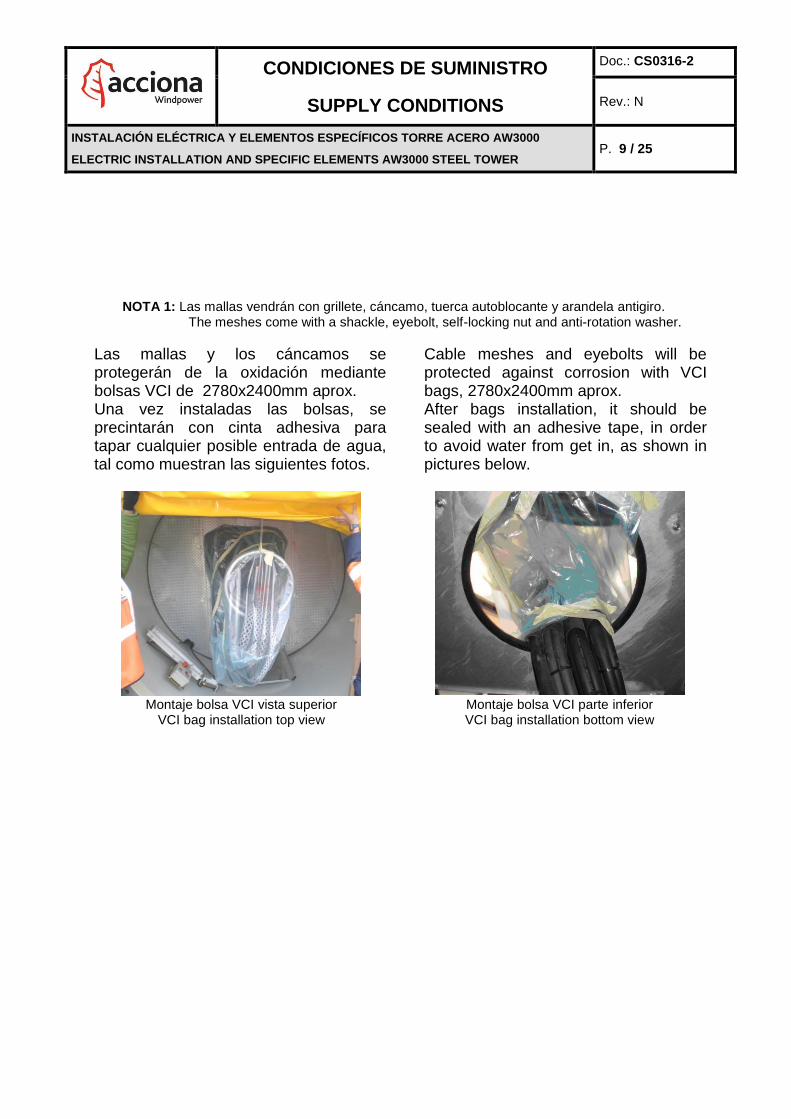
NOTA 1: Las mallas vendrán con grillete, cáncamo, tuerca autoblocante y arandela antigiro. The meshes come with a shackle, eyebolt, self-locking nut and anti-rotation washer.
Las mallas y los cáncamos se protegerán de la oxidación mediante bolsas VCI de 2780x2400mm aprox. Una vez instaladas las bolsas, se precintarán con cinta adhesiva para tapar cualquier posible entrada de agua, tal como muestran las siguientes fotos.
Cable meshes and eyebolts will be protected against corrosion with VCI bags, 2780x2400mm aprox. After bags installation, it should be sealed with an adhesive tape, in order to avoid water from get in, as shown in pictures below.
Montaje bolsa VCI vista superior Montaje bolsa VCI parte inferior
VCI bag installation top view VCI bag installation bottom view
En la parte inferior, el sobrante de cada cable se extenderá individualmente sobre el soporte haciendo los ascensos y descensos necesarios de los cables. Los sobrantes de los cables de estator deben tener un radio de curvatura mínimo de 15 veces el diámetro y de 5 veces para el resto de cables.
4.3.1 Colocación Aros – Cables
Se deben cumplir los siguientes aspectos:
- Se debe mantener la secuencia de
At the bottom, lay the surplus of each cable individually on the support so that the cable goes up and then down. The surplus of the stator cables must have a minimum bending radius of 15 times the external diameter, and 5 times for the rest of cables.
4.3.1 Placing the cables in the rings Ensure the following:
- Maintain the sequence when tying the
Tipo de terna Type of triad
Cantidad Quantity
Ø Malla Ø Mesh
Rotor 3 Ø65-Ø75
Estator/Stator 1 Ø65-Ø75

CONDICIONES DE SUMINISTRO
SUPPLY CONDITIONS
Doc.: CS0316-2
Rev.: N
INSTALACIÓN ELÉCTRICA Y ELEMENTOS ESPECÍFICOS TORRE ACERO AW3000
ELECTRIC INSTALLATION AND SPECIFIC ELEMENTS AW3000 STEEL TOWER P. 10 / 25
embridamiento entre los diferentes aros para no producir torcimientos en la bajada.
- Los aros vendrán embridados al cable de alimentación de estator y el conjunto resultante se embridará a la escalera o soporte. En los agujeros libres de los aros se colocarán las bridas para el resto de los cables.
- La distancia entre aros será la indicada en el plano del tramo
cables between the rings to avoid twisting them as you lower them.
- Tie the rings to the stator supply cable
and the resulting assembly to the ladder or support. In the free holes of the rings, place the wire ties for the rest of cables.
- The section drawing shows the distance between rings
4.3.2 Requisitos Suplementarios
- Todas las ternas irán embridadas con brida tipo UNEX de 7,6mm color negro.
- Se identificarán los cables con cinta de color según sea la fase, a 10cm y a 100cm de ambas puntas.
- Los dos extremos de todos los cables se protegerán con termorretráctil.
- En el caso de que el fabricante suministre los cables en bobina sin cortar, se procederá a realizar el
4.3.2 Supplementary requirements
- Tie all the wire triad with a black 7.6mm UNEX wire tie.
- Identify the cables with coloured tape
according to the phase 10cm and 100cm from each end.
- Protect both ends of all the wires with a heat shrink hood.
- In case cable manufacturer supply cable reels with the total length, cuts should be done to achieve proper
BRIDAS / WIRE TIES
Tipo / Type: UNEX
Longitud / Length: 300mm
Anchura / Width: 7,6mm
Color / Colour: Negro/ Black
AROS / RINGS Pos. 1: Libre / Free Pos. 2: Terna 1 rotor / Rotor triad 1 Pos. 3: Terna 2 rotor / Rotor triad 2 Pos. 4: Terna 3 rotor / Rotor triad 3 Pos. 5: Terna estátor / Stator triad

CONDICIONES DE SUMINISTRO
SUPPLY CONDITIONS
Doc.: CS0316-2
Rev.: N
INSTALACIÓN ELÉCTRICA Y ELEMENTOS ESPECÍFICOS TORRE ACERO AW3000
ELECTRIC INSTALLATION AND SPECIFIC ELEMENTS AW3000 STEEL TOWER P. 11 / 25
corte de cada tramo teniendo en cuenta la longitud marcada en lista base. El fabricante realizará marcas bien visibles para delimitar la longitud exacta, indicando la posición para realizar cada corte.
Cuadro Resumen Longitudes de Cables
cable length that fits with BOM, for each tower section. Manufacturer will provide consistent and accurate marks that show where the cut should be done.
Cable lengths summary table
TO
RR
E
TO
WE
R
Tipo de tramo / Type of section
Tipo cable / Type of cable
Etiqueta / Tag
Nº de cortes / Number of cuts
Sobrante inferior (m) /
Lower surplus (m)
Sobrante superior /
Upper surplus (m)
Inferior / Lower
Rotor
RZ1-K 1.8/3kV
WTM9.4 a / to
WTM9.12 9 6,5 0,35
400V
RZ1-K 0,6/1kV WTM1.1 a/to
WTM1.4 4 6.5 0.35
Intermedios / Intermediates
Rotor
RZ1-K 1.8/3kV
WTM9.4 a / to
WTM9.12 9 0,35 0,35
400V
RZ1-K 0,6/1kV WTM1.1 a/to
WTM1.4 4 0.35 0.35
Superior / Upper
Rotor
DZ-F 1.8/3kV
WTM9.4 a / to
WTM9.12 9 S1 10
Estator / Stator
DHA 8,7/15kV
WTM9.1 a / to
WTM9.3 3 S1 13
5. INSTALACIÓN LUMINARIAS
A lo largo de la torre se colocarán las luminarias en las posiciones indicadas en el plano entregado por Acciona Windpower. Se deberán tener en cuenta los siguientes puntos:
Los cables estarán exentos de daños en la capa de protección.
Se instalarán puntos de luz de 2 x 18 W en las posiciones indicadas en los planos.
Todas las luminarias deben ser válidas para 220/230V y 50/60Hz.
Las lámparas de emergencia contarán con una batería con una capacidad que permita una autonomía de al
5. INSTALLING THE LIGHTS
Throughout the tower, place the lights in the positions indicated in the drawing delivered by Acciona Windpower. Take into account the following points:
The protective layer of the cable must not be damaged.
Install 2 x 18W light fittings in the positions indicated in the drawings.
All the lights must be able to work at 220/230V and 50/60Hz.
The emergency lights will have a battery with a capacity that allows the light to stay on for at least 30 minutes.

CONDICIONES DE SUMINISTRO
SUPPLY CONDITIONS
Doc.: CS0316-2
Rev.: N
INSTALACIÓN ELÉCTRICA Y ELEMENTOS ESPECÍFICOS TORRE ACERO AW3000
ELECTRIC INSTALLATION AND SPECIFIC ELEMENTS AW3000 STEEL TOWER P. 12 / 25
menos 30 minutos y serán montadas en las posiciones indicadas en las páginas siguientes.
El cable de luminaria será RZ1-K de sección 4G1,5mm2. Los colores de los cables serán:
Negro: Fase Marrón: Fase conmutada Gris: Neutro Amarillo-verde: Tierra
El cable de luminaria llevará una etiqueta en cada extremo en la que vendrá indicado el código (ver tabla)
A la entrada de la torre se colocará un interruptor de encendido de luces con toma de corriente de 15 A.
Las tomas de conexión y de corriente serán IP 55.
Como se muestra en los planos de torre de las siguientes páginas, se deben dejar extensiones de cable (WTL0.3.x y WTL0.4.x) con conectores (macho ó hembra, según se indica) en los siguientes tramos. El cable se fijará mediante brida tipo UNEX al rejiband o escalera.
Mount them in the positions indicated on next pages.
The light wire will be RZ1-K of section 4G1.5mm2. The colours of the wires will be: Black: Phase Brown: Switched phase Grey: Neutral Yellow-green: Earth
The light cable has a tag on every end. See the table for the code.
At the entrance to the tower, place a light switch with a 15A socket.
The plugs and sockets will be IP 55
As in the tower drawings on the following pages, leave wire extensions (WTL0.3.x and WTL0.4.x) with connectors (male or female, as indicated) in the following sections. Tie the light wire to the rejiband or ladder with a UNEX wire tie.
Tramo/ Section
Código cable
luminarias / Lights
cable code
Extensión/ Extension
Tipo conector/ Connector type
Inferior/ Lower WTL0.3.1 Inf/ Lower : 5m Macho/ Male
Sup/ Upper : 0m Hembra/ Female
T2 WTL0.3.2
Inf/ Lower : 2m Sup/ Upper : 0m
Macho/ Male Hembra/ Female
T3 WTL0.3.3
T4 (solo Torres T92-95.5 / Only T92-
95.5 towers)
WTL0.3.4
Superior/ Upper WTL0.3.5 Inf/ Lower : 2m Macho/ Male
Sup/ Upper : Termina en caja conexión/ Goes to junction box
NOTA: Antes de las luminarias se colocan cajas de registro atornillada en el soporte de la luminaria.
NOTE: Before placing the lights, screw weatherproof square junction boxes onto the light support.

CONDICIONES DE SUMINISTRO
SUPPLY CONDITIONS
Doc.: CS0316-2
Rev.: N
INSTALACIÓN ELÉCTRICA Y ELEMENTOS ESPECÍFICOS TORRE ACERO AW3000
ELECTRIC INSTALLATION AND SPECIFIC ELEMENTS AW3000 STEEL TOWER P. 13 / 25
La tornillería necesaria para la instalación así como los elementos de la lista base, serán suministrados por el fabricante de la torre salvo indicación en contra en el pedido.
Todas las conexiones se realizarán con punteras. Usar bornas dobles cuando se conecten dos cables en un terminal simple.
En la luminaria estándar el cable negro llevará una regleta en su extremo libre (ver foto)
El cableado de las regletas se hará según lo indicado en el punto 5.1.
La bajada de cable se hará embridando éste a la sirga de bajada de cable, siguiendo la pared de la torre.
Las pantallas de las luminarias irán embridadas en sus respectivos soportes, para evitar daños durante el transporte.
No está permitido cable sin la capa exterior de protección fuera de la caja plexo. Los conos de entrada de cable se cortarán de tal forma que ajusten al diámetro del cable para así evitar la entrada de humedad y/o agua.
Se comprobará en cada tramo de torre el correcto cableado y funcionamiento de las luminarias. Además se mantendrá la corriente el tiempo necesario para cargar las baterías de las luminarias de emergencia y comprobar su funcionamiento (que cuando se quita la alimentación del hilo negro, las luminarias de emergencia se encienden)
Chequear la instalación siguiendo los siguientes pasos:
Desconectar los cables marrón y negro de la clavija superior y cubrir
The tower manufacturer will supply necessary fasteners as well as the elements on the part list except when otherwise indicated in the order.
Make all the connections with terminal spade tags. Use double spade tags when connecting two wires into a single terminal.
Put a terminal block in the black free end wire in the standard light (see picture)
Wire the terminal blocks according to point 5.1.
Lower the wire by tying it to the guidance cable, following the tower wall.
Tie the lights to their respective supports to avoid damage during transport.
There must not be any bare wires outside the plexo box. Cut the cones where the wires enter the box so that they fit the diameter of the wire and thus keep moisture and/or water out.
You must check in each of the tower sections the correct cabling and light functioning, as well as the plugs one. In addition leave the current switched on long enough to charge and test the emergency light batteries (when power is removed from the black wire connection, the emergency lights shall come on)
Check the electrical installation as follows:
Disconnect the Black and Brown wires from the plug at the top. Cover the

CONDICIONES DE SUMINISTRO
SUPPLY CONDITIONS
Doc.: CS0316-2
Rev.: N
INSTALACIÓN ELÉCTRICA Y ELEMENTOS ESPECÍFICOS TORRE ACERO AW3000
ELECTRIC INSTALLATION AND SPECIFIC ELEMENTS AW3000 STEEL TOWER P. 14 / 25
los extremos con bornas.
Conectar los hilos en la parte inferior del tramo como sigue: o Marrón: alimentación 230V a
través de un interruptor (en tramo 2 y 3 usar uno provisional)
o Negro: fase 230V o Gris: Neutro o Amarillo-Verde: tierra
Encender y apagar al menos 3 veces. Comprobar que se encienden y apagan.
Con el interruptor en posición apagado, comprobar que las luminarias de emergencia están cargando (led de carga iluminado)
Dejar el cable negro conectado al menos 30 minutos
Soltar el cable negro y comprobar que las luminarias de emergencia se encienden
Reconectar los cables negro y marrón de las clavijas
En las siguientes páginas se muestran los esquemas (no a escala, para ver la ubicación real de los elementos consultar planos) de conexión de las luminarias divididos por tramos. A continuación se incluye una lista-base de los elementos necesarios en la instalación y finalmente se incluye una figura para detallar la instalación en la parte inferior del primer tramo de la torre.
5.1 Posición caja conexión entre tramos
Colocar la caja de conexión de luminaria en el último arriostramiento de cada tramo de acuerdo a la siguiente imagen (imagen vista desde la nacelle a cimentación) incluyendo dos anillos separadores:
loose ends with terminal blocks.
Connect the wires at the bottom of the tower section as follows: o Brown: 230V supplied through a
switch (in the 2nd and 3rd section use a provisional switch)
o Black: phase 230V o Grey: Neutral o Yellow-green: ground
Flip the switch on and off at least 3 times. Check the lights turn on and off.
With the switch in the off position, check to make sure the emergency lights are charging (charging indicator on the light is lit).
Leave the unswitched 230V connected for at least 30 minutes
Remove the power from the Black wire connection and check that the emergency lights turn on.
Reconnect the black and brown plug cables
The next pages show the light connection diagrams (not to scale, for the actual position of the elements see drawings) for each section. A part list of the elements necessary for installation and the installation details for the bottom of the first tower section are also included.
5.1 Light junction box position
Assembly the light junction box at the last bridging of each tower section in accordance to the next image (image is shown from the nacelle towards the foundation) adding two spacer rings

CONDICIONES DE SUMINISTRO
SUPPLY CONDITIONS
Doc.: CS0316-2
Rev.: N
INSTALACIÓN ELÉCTRICA Y ELEMENTOS ESPECÍFICOS TORRE ACERO AW3000
ELECTRIC INSTALLATION AND SPECIFIC ELEMENTS AW3000 STEEL TOWER P. 15 / 25
Para ello será necesario realiza dos taladros en el arriostramiento de acuerdo al siguiente esquema:
5.2 Esquemas de conexión de luminarias
El cableado dentro de las luminarias será como muestra la siguiente figura:
It must be drilled two holes in the bridging in accordance to the next detail:
5.2 Light connection diagrams
The wiring of the lights must be as shown in the following picture:
Ejemplo de cableado de una luminaria normal Ejemplo de cableado de una luminaria de emergencia Example of non-emergency light wiring Example of emergency light wiring
N
T
L
L
N
T
1
2

CONDICIONES DE SUMINISTRO
SUPPLY CONDITIONS
Doc.: CS0316-2
Rev.: N
INSTALACIÓN ELÉCTRICA Y ELEMENTOS ESPECÍFICOS TORRE ACERO AW3000
ELECTRIC INSTALLATION AND SPECIFIC ELEMENTS AW3000 STEEL TOWER
P. 16 / 25
Tramo Inferior
Lower Section
Tramos Intermedios
Intermediate Sections
Tramo Superior
Top Section
Caja Derivación Luminarias
Light Junction Box
Conexión en luminarias Estandar
Standard Light wiring
Conexión en luminarias emergencia (5 borneros)
Emergency light wiring (5 terminals block)
(L) Switched phase
(N) Neutral phase
(T) Earth/ GroundYellow/ Green
Gray
Brown
(L) FASE CONMUTADA
(N) FASE NEUTRO
(T) TIERRAAMA/VERDE
Gris
MARRON
(1) FASE 230Vac CTEBLACK
(1) Constant 230VacBlack
ESQUEMAS DE CONEXIÓN DE LUMINARIAS/ LIGHT CONNECTION DIAGRAMS
Conexión en luminarias emergencia (4 borneros)
Emergency light wiring (4 terminals block)
Nota: La línea de enchufes sólo se instalará si así lo indica el Departamento de Compras
Note: Purchase Department will decide if the socket line should be installed.

CONDICIONES DE SUMINISTRO
SUPPLY CONDITIONS
Doc.: CS0316-2
Rev.: N
INSTALACIÓN ELÉCTRICA Y ELEMENTOS ESPECÍFICOS TORRE ACERO AW3000
ELECTRIC INSTALLATION AND SPECIFIC ELEMENTS AW3000 STEEL TOWER
P. 17 / 25
5.3 Conexionado
A continuación se muestra el conexionado correcto de los diferentes elementos:
5.3.1 Luminaria de emergencia
a) La fase marrón debe alimentar el circuito estándar del fluorescente, lo mismo que en el resto de luminarias.
b) Los hilos negro y gris alimentan el circuito de la batería de emergencia.
Ambos circuitos están claramente
diferenciados.
5.3.2 Caja de derivación
En las dos figuras siguientes, se indica la forma de conexionar las cajas de conexión así como la posición en el soporte de luminaria.
5.3 Connection
Connect the various elements as follows:
5.3.1 Emergency light
a) The brown phase must supply the fluorescent standard circuit as well as the rest of the lights.
b) The black and grey wires supply the emergency battery circuit.
Both circuits are clearly differentiated.
5.3.2 Junction box
The two following figures show how to connect the junction boxes and where to position them on the light support.
Luminaria / Light
A luminaria siguiente / To next light
De luminaria anterior /
From previous light

CONDICIONES DE SUMINISTRO
SUPPLY CONDITIONS
Doc.: CS0316-2
Rev.: N
INSTALACIÓN ELÉCTRICA Y ELEMENTOS ESPECÍFICOS TORRE ACERO AW3000
ELECTRIC INSTALLATION AND SPECIFIC ELEMENTS AW3000 STEEL TOWER P. 18 / 25
5.4 Desglose de los artículos que componen cada elemento
5.4 Breakdown of the parts that make up each element
ELEMENTO / ELEMENT CONSTA DE / CONSIST OF:
Lámpara / Light
A: Luminaria / Light F: Regleta de conexiones / Terminal Block I: Caja de conexiones / Junction Box M: Tubo Fluorescente / Fluorecent tube
Lámpara de Emergencia / Emergency Light
B: Luminaria con kit de emergencia / Light with emergency kit F: Regleta de conexiones / Terminal Block I: Caja de conexiones / Junction Box M: Tubo fluorescente / Fluorescent tube
En la página siguiente, se adjunta una foto que muestra el tendido orientativo de los cables WTL0.3.1 y WTL0.4.1 en la parte inferior del primer tramo. Hay que tener en cuenta que los enchufes de 230Vac sólo irán instalados si así lo especifica el Dpto. Compras.
The photo on the following page shows the layout of cables WTL0.3.1 and WTL0.4.1, at the bottom of the first section. Take into account that the 230Vac sockets must be assembled only if it so required by the Purchasing Department.
Punto 1: Punto donde el cable WTL0.3.1 y WTL0.4.1 se separa de la torre para ir
Point 1: Point where wire WTL0.3.1 and WTL0.4.1 is separated from the tower to
1
2
3
4
5

CONDICIONES DE SUMINISTRO
SUPPLY CONDITIONS
Doc.: CS0316-2
Rev.: N
INSTALACIÓN ELÉCTRICA Y ELEMENTOS ESPECÍFICOS TORRE ACERO AW3000
ELECTRIC INSTALLATION AND SPECIFIC ELEMENTS AW3000 STEEL TOWER P. 19 / 25
hasta el enchufe. El trazado de este cable es el marcado en la figura y será desde el punto 1 al 3 a través del punto 2 y bajada al interruptor de la puerta (punto 4) y después al punto 5. Punto 4: Interruptor conmutador + toma (2p+T) que irán instalados como el resto de los enchufes en una caja tipo E.
Cable WTL0.3.1 y WTL0.4.1 en el punto 5 se formará un ovillo de 5m acabado en una clavija.
5.5 Requisitos Suplementarios
Irán marcados con sus etiquetas correspondientes, los siguientes cables:
- WTL0.3.1: A la salida de la toma 2p+T
(punto 4) y en el extremo opuesto (punto 5): Clavija 2p+T
- WTL0.3.1: A la entrada al interruptor de la puerta (punto 4)
go up to the plug. The figure shows the layout of this wire, which will run from point 1 to 3 through point 2 and down to the door switch (point 4) and after that to the point 5. Point 4: Change-over switch + socket (2p+T) are installed along with the rest of the sockets in box E type.
Cable WTL0.3.1 and WTL0.4.1 at point 5 make a wind up 5m of the wire with a plug at the end.
5.5 Supplementary requirements
Mark the following wires with their corresponding labels:
- WTL0.3.1: At the socket end 2p+T
(point 4) and at the opposite end (point 5): Plug 2p+T.
- WTL0.3.1: At the door switch input (point 4)
6. KIT 230Vac
En las máquinas indicadas por el departamento de compras, se instalará el Kit 230Vac.
Habrá tomas de corriente 230V 15A (2p + t) en cada unión de tramos torre.
Las tomas de conexión y de corriente serán IP 55.
Cada enchufe constará de los siguientes elementos:
6. 230V KITac Assemble the 230Vac kit as shown below in the towers specified by the purchase department.
Every tower section union will have a 230V 15A (2 p + t) socket.
The plugs and sockets will be IP 55.
Each socket will have the following components:
ELEMENTO / ELEMENT CONSTA DE / CONSIST OF:
Enchufe / Socket
E: Caja 2 Elementos Componible PLEXO 55S / Box 2 Elements atacable PLEXO 55S C: Toma 2P+T Lateral Componible PLEXO 55S / Socket 2P+T side attachable PLEXO 55S F: Regleta de conexiones / Terminal block G: Tapa ciega / Opaque cover H: Cono multidiámetro PLEXO 55 / Multidiameter cone PLEXO 55

CONDICIONES DE SUMINISTRO
SUPPLY CONDITIONS
Doc.: CS0316-2
Rev.: N
INSTALACIÓN ELÉCTRICA Y ELEMENTOS ESPECÍFICOS TORRE ACERO AW3000
ELECTRIC INSTALLATION AND SPECIFIC ELEMENTS AW3000 STEEL TOWER P. 20 / 25
El cable será RZ1-K de sección 3G2,5mm2. Los colores de los cables serán:
Marrón: Fase Azul: Neutro Verde-amarillo: Tierra
El cable llevará una etiqueta con su código en cada extremo (ver tabla).
Se deben dejar extensiones de cable (WTL0.4.x) con conectores (macho o hembra, según se indica) en los siguientes tramos. El cable se fijará mediante brida tipo UNEX al rejiband o escalera.
The cable will be RZ1-K of section 3G2.5mm2. The colours of the cables will be: Brown: Phase Grey: Neutral Green-yellow: Earth
The cable has a tag on every end. See the table for the code.
Leave wire extensions (WTL0.4.x) with connectors (male or female, as indicated) in the following tower sections. Tie the light wire to the rejiband or ladder with a UNEX wire tie.
Tramo/ Section
Código cable
enchufes / Sockets
cable code
Extensión/ Extension
Tipo conector/ Connector type
Base torre WTL0.4.0 Termina en enchufe/ Ends in the socket.
Inferior/ Lower WTL0.4.1 Inf/ Lower : 5m Macho/ Male
Sup/ Upper : 0m Hembra/ Female
T2 WTL0.4.2
Inf/ Lower : 2m Sup/ Upper : 0m
Macho/ Male Hembra/ Female
T3 WTL0.4.3
T4 (solo Torres
T92-95.5 / Only T92-95.5 towers)
WTL0.4.4
Superior/ Upper WTL0.4.5 Inf/ Lower : 2m Macho/ Male
Sup/ Upper : Termina en caja conexión/ Goes to junction box
La tornillería necesaria para la instalación así como los elementos de la lista base, serán suministrados por el fabricante de la torre salvo indicación en contra en el pedido.
Todas las conexiones se realizarán con punteras. Usar bornas dobles cuando se conecten dos cables en un terminal simple.
El cableado de las regletas se hará según lo indicado abajo:
The tower manufacturer will supply necessary fasteners as well as the elements on the part list except when otherwise indicated in the order.
Make all the connections with terminal spade tags. Use double spade tags when connecting two wires into a single terminal.
Wire the terminal blocks as shown in the diagram below:

CONDICIONES DE SUMINISTRO
SUPPLY CONDITIONS
Doc.: CS0316-2
Rev.: N
INSTALACIÓN ELÉCTRICA Y ELEMENTOS ESPECÍFICOS TORRE ACERO AW3000
ELECTRIC INSTALLATION AND SPECIFIC ELEMENTS AW3000 STEEL TOWER P. 21 / 25
La bajada de cable se hará
embridando éste a la sirga de bajada de cable, siguiendo la pared de la torre.
Se comprobará en cada tramo de torre el correcto cableado y funcionamiento de enchufes.
Los siguientes cables irán marcados con sus etiquetas correspondientes: o WTL0.4.1: A la salida de la toma
2p+T (punto 4) y en el extremo opuesto (punto 5): Clavija 2p+T
o WTL0.4.1: A la entrada al enchufe de la puerta (punto 4)
Lower the wire by tying it to the guidance cable, following the tower wall.
Check the correct cabling and sockets functioning in each of the tower sections.
following wires must be marked with their corresponding labels: o WTL0.4.1: At the socket end 2p+T
(point 4) and at the opposite end (point 5): Plug 2p+T.
o WTL0.4.1: At the door switch input (point 4)
7. KIT 120V
En las máquinas indicadas por el departamento de compras, se instalará el Kit 120V como se indica a continuación. Las tomas de corriente irán colocadas en la zona superior de cada tramo se colocará una toma de corriente.
7.1 Colocación del cuadro del transformador con toma de corriente
Colocar el cuadro del transformador dentro de la cabina del elevador, fijándola a los peldaños de este
7. 120V KIT Assemble the 120V kit as shown below in the towers specified by the purchase department The sockets must be placed in the upper part of each tower section.
7.1. Positioning the transformer cabinet with socket
Place the transformer cabinet inside the elevator cabinet, fixing it to the rungs by means of slip jackets.

CONDICIONES DE SUMINISTRO
SUPPLY CONDITIONS
Doc.: CS0316-2
Rev.: N
INSTALACIÓN ELÉCTRICA Y ELEMENTOS ESPECÍFICOS TORRE ACERO AW3000
ELECTRIC INSTALLATION AND SPECIFIC ELEMENTS AW3000 STEEL TOWER P. 22 / 25
mediante cinchas. 7.2 Tomas de corriente en zona
superior de tramos
7.2.1 Toma corriente tramo 1
Colocar la toma de corriente en la orejeta común para tomas de 220VAC y 110 ó 120VAC utilizando 4 tornillos M6, 4 arandelas M6 y 4 tuercas M6 autoblocantes.
7.2.2 Toma corriente tramos intermedios
Se necesita un suplemento para colocar la toma de 120Vac en vertical. Unir el suplemento a la orejeta utilizando 4 tornillos M6, 4 arandelas M6 y 4 tuercas M6 autoblocantes. Unir la toma de 120Vac al suplemento utilizando 4 tornillos M6, 4 arandelas M6 y 4 tuercas M6 autoblocantes.
Montar un prensa en la caja de la toma de corriente para permitir la salida de dos cables (uno hacia la nacelle y otro hacia el tercer tramo de torre). Usar Loctite para fijar bien el prensa.
7.2. Placing the sockets in the
upper tower sections
7.1.1 1st tower section socket
Place the sockets in the common lug for the 220VAC and 110 or 120VAC using 4 M6 bolts, 4 M6 washers and 4 M6 self-locking nuts.
7.1.2 Intermediates tower sections
socket
A plate which allows positioning the 120Vac socket in vertically is necessary. Fix the plate to the lug using 4 M6 bolts, 4 M6 washers and 4 M6 self-locking nuts. Finally join the 120Vac socket with the plate using 4 M6 bolts, 4 M6 washers and 4 M6 self-locking nuts. Assemble an extra cable gland in the socket box in order to allow two cables out (one to the nacelle and another one to the third tower section) . Use some Loctite to ensure the gland will not be moved.

CONDICIONES DE SUMINISTRO
SUPPLY CONDITIONS
Doc.: CS0316-2
Rev.: N
INSTALACIÓN ELÉCTRICA Y ELEMENTOS ESPECÍFICOS TORRE ACERO AW3000
ELECTRIC INSTALLATION AND SPECIFIC ELEMENTS AW3000 STEEL TOWER P. 23 / 25
7.2.3 Toma corriente tramo superior
Igual que en el tramo intermedio, pero sin prensa y contratuerca extra.
Tomas corriente de tramos 2 y 3
Sockets of 2nd
and 3rd
tower sections
7.3 Guiado cables tomas de corriente
Unir la toma superior del primer tramo con el cable WTL1.1 y embridarlo a la sirga de luminaria y manguera de recogida de aceite. En la parte inferior del tramo dejar el resto de cable en una bobina.
Conectar el cable WGL7.1 en el armario del transformador y dejar el cable en una bobina.
Unir la toma superior de los tramos intermedios con el cable WTL1.2, WTL1.3, WTL1.4, (dependiendo del tramo) y embridarlo a la sirga de luminaria y manguera de recogida de aceite. En la parte inferior del tramo dejar el resto de cable en una bobina.
Unir la toma superior del tramo superior con el cable WTL1.5 y embridarlo a la sirga de luminaria y manguera de recogida de aceite. En la parte inferior del tramo dejar el resto de cable en una bobina. Conectar según el siguiente esquema:
7.1.3 Upper tower section socket
The same as in intermediate tower section, but without extra cable gland and locknut.
Suplemento para el montaje de tomas en vertical.
Plate to assemble the sockets vertically.
7.3. Wiring of the Sockets
Join the socket placed in the upper part of the first tower section with the WTL1.1 cable and tie to the towline of the lights and the oil collection hose. Leave the cable on a reel in the lower part of the section.
Connect the WGL7.1 cable to the transformer cabinet and leave the cable on a reel.
Join the socket placed in the intermediate tower section with the WTL1.2, WTL1.3, WTL1.4, cable (depending on the tower section) and tie to the towline of the lights and the oil collection hose. Leave the cable on a reel in the lower part of the section
Join the socket placed in the upper part of the upper tower section with the WTL1.5 cable and tie to the towline of the lights and the oil collection hose. Leave the cable on a reel in the lower part of the section Connect as shown on the diagram:

CONDICIONES DE SUMINISTRO
SUPPLY CONDITIONS
Doc.: CS0316-2
Rev.: N
INSTALACIÓN ELÉCTRICA Y ELEMENTOS ESPECÍFICOS TORRE ACERO AW3000
ELECTRIC INSTALLATION AND SPECIFIC ELEMENTS AW3000 STEEL TOWER P. 24 / 25
CODIGO DE COLORES / DESCRIPTION OF WIRES
MA ...................................................Marrón / Brown
AZ............................................................Azul / Blue
AMA.................................................Amarillo / Yelow
VE.......................................................Verde / Green
WTL1.5
AZAMA/
VEMAAZ
AMA/
VEMA
AZAMA/
VEMA
WTL1.2
AZAMA/
VEMAAZ
AMA/
VEMA
TOMA DE CORRIENTE TRAMO 2º,3º,4º
2nd, 3rd, 4th SECTION SOCKET
TOMA DE CORRIENTE TRAMO 5º
5th SECTION SOCKET
TOMA DE CORRIENTE TRAMO 1
FIRST SECTION SOCKET
WTL1.1
AMA/
VEMA AZ
AR
MA
RIO
TR
AN
SF
OR
MA
DO
R
TR
AN
SF
OR
ME
R C
AB
INE
T
AMA/
VEMA AZ
WGL7.1A CONECTAR EN CAMPO
TO CONNECT ON SITE
A CONECTAR EN CAMPO
TO CONNECT ON SITE
A CONECTAR EN CAMPO
TO CONNECT ON SITE

CONDICIONES DE SUMINISTRO
SUPPLY CONDITIONS
Doc.: CS0316-2
Rev.: N
INSTALACIÓN ELÉCTRICA Y ELEMENTOS ESPECÍFICOS TORRE ACERO AW3000
ELECTRIC INSTALLATION AND SPECIFIC ELEMENTS AW3000 STEEL TOWER P. 25 / 25
8. TAMBOR CABLES
8.1 Balancín
El montaje del balancín del tambor de cables se efectuará de tal forma que permita su oscilación. Para ello no se apretarán del todo los tornillos pero se asegurará de haber pasado el material de goma de las tuercas auto blocantes.
9. DOCUMENTACIÓN
De cliente a proveedor
La presente Condición de suministro CS0316-2
Condición de suministro CS0316-6 Fijación cables transporte en tramo superior torre acero AW3000.
8. CABLE GUIDE LOOPING 8.1 Lever arm
Mount the lever arm of the cable guide so that it can swing. To do so, do not tighten the bolts all the way, but make sure you pass the rubber on the self-locking nuts.
9. DOCUMENTS
From client to supplier
This supply condition CS0316-2
Supply condition CS0316-6 Securing the cable inside upper section for transport in the AW3000 steel tower.


