Embed Size (px)
Citation preview
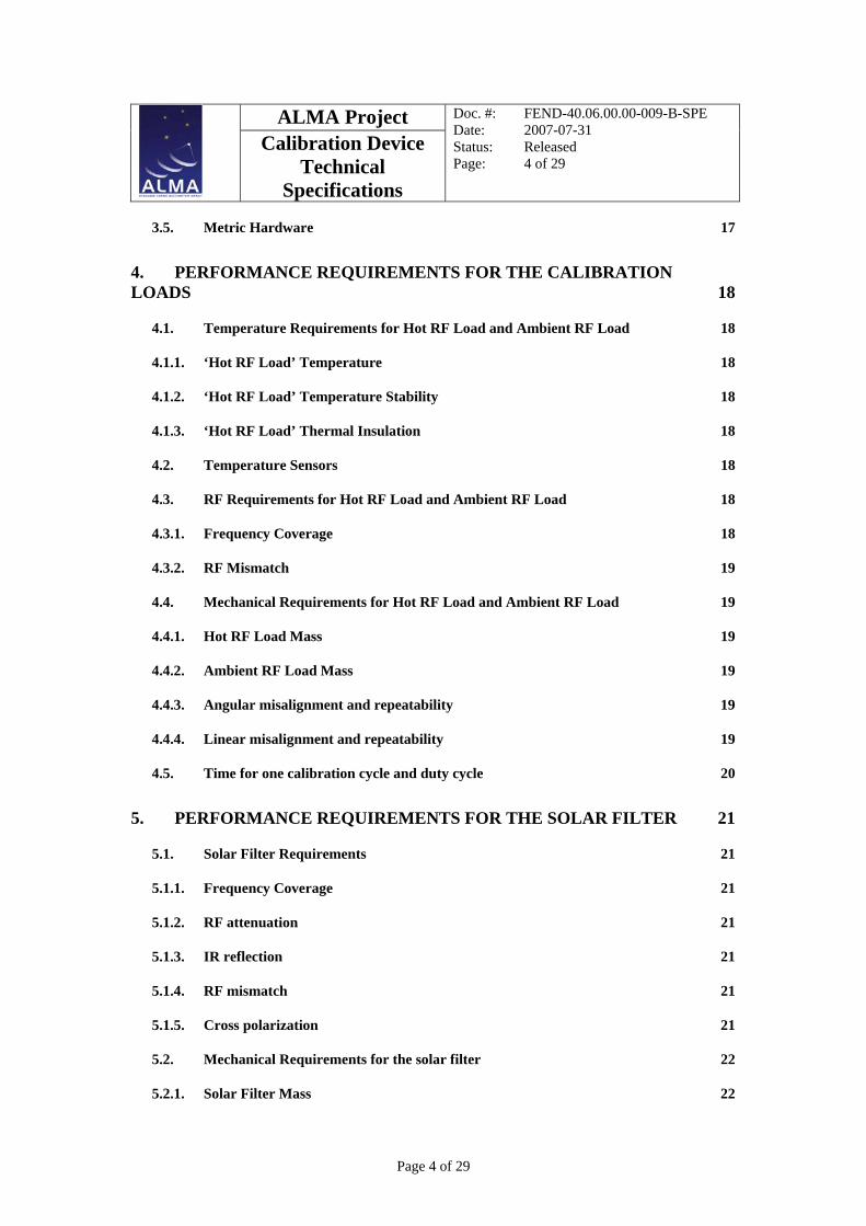
Calibration Device Technical Specifications
FEND-40.06.00.00-009-B-SPE
Version: B
Status: Released
2007-07-31
Prepared By: Name and Signature Organization Date F. PATT
European Organisation for Astronomical Research in the Southern Hemisphere
Approved By FE IPT Leaders Name(s) and Signature(s) Organization Date G.H. TAN J. WEBBER
European Organisation for Astronomical Research in the Southern Hemisphere NRAO
Approved By SE&I IPT Leaders Name(s) and Signature(s) Organization Date C. HAUPT R. SRAMEK
European Organisation for Astronomical Research in the Southern Hemisphere NRAO
Approved By JAO Name and Signature Organization Date M. TARENGHI
JAO
Released By ESO
Name and Signature Organization Date H. RYKACZEWSKI
European Organisation for Astronomical Research in the Southern Hemisphere

ALMA Project
Calibration Device Technical
Specifications
Doc. #: FEND-40.06.00.00-009-B-SPE Date: 2007-07-31 Status: Released Page: 2 of 29
Page 2 of 29
Change Record Version Date Affected
Section(s) Change request
#
Reason/remarks
A 2006-07-20 All N/A First document issue B 2007-07-31 1
2 4.1.3 4.3 4.4.
5 5.2.
6 7.1. 7.4. 8.1
9.12.
9.1.3.
Update Product Tree, ADL, RDL Update Table 1 Update Thermal Insulation Requirement Update calibration requirement Include absolute position accuracy Update solar filter requirements Include absolute position accuracy Update QWP requirement Update mass requirement Update Eigen Frequency Requirement Editorial change Correction in Operating Temperature Requirement Correction in Relative Humidity requirement

ALMA Project
Calibration Device Technical
Specifications
Doc. #: FEND-40.06.00.00-009-B-SPE Date: 2007-07-31 Status: Released Page: 3 of 29
Page 3 of 29
TABLE OF CONTENTS
1. INTRODUCTION 7
1.1. Purpose 7
1.2. Scope 7
1.3. Applicable Documents List (ADL) 8
1.4. Reference Documents List (RDL) 8
1.5. Acronyms 9
1.6. Verb Convention 9
1.7. Requirements Numbering 9
2. DESCRIPTION 10
2.1. Equipment Definition 10
2.2. Definition of Coordinate System 13
2.3. Description of the Cryostat layout, windows and IR-filters positions 14
3. GENERAL REQUIREMENTS 16
3.1. Operation Modes 16
3.1.1. Operational 16
3.1.2. Park position 16
3.1.3. Non-Operational 16
3.1.4. Transport Conditions 16
3.2. Compatibility with ALMA Front End Sub-System 16
3.3. Design for Production 17
3.3.1. Technology 17
3.3.2. Series Production 17
3.3.3. Standard Parts 17
3.4. Cables and Connectors 17
ALMA Project
Calibration Device Technical
Specifications
Doc. #: FEND-40.06.00.00-009-B-SPE Date: 2007-07-31 Status: Released Page: 4 of 29
Page 4 of 29
3.5. Metric Hardware 17
4. PERFORMANCE REQUIREMENTS FOR THE CALIBRATION LOADS 18
4.1. Temperature Requirements for Hot RF Load and Ambient RF Load 18
4.1.1. ‘Hot RF Load’ Temperature 18
4.1.2. ‘Hot RF Load’ Temperature Stability 18
4.1.3. ‘Hot RF Load’ Thermal Insulation 18
4.2. Temperature Sensors 18
4.3. RF Requirements for Hot RF Load and Ambient RF Load 18
4.3.1. Frequency Coverage 18
4.3.2. RF Mismatch 19
4.4. Mechanical Requirements for Hot RF Load and Ambient RF Load 19
4.4.1. Hot RF Load Mass 19
4.4.2. Ambient RF Load Mass 19
4.4.3. Angular misalignment and repeatability 19
4.4.4. Linear misalignment and repeatability 19
4.5. Time for one calibration cycle and duty cycle 20
5. PERFORMANCE REQUIREMENTS FOR THE SOLAR FILTER 21
5.1. Solar Filter Requirements 21
5.1.1. Frequency Coverage 21
5.1.2. RF attenuation 21
5.1.3. IR reflection 21
5.1.4. RF mismatch 21
5.1.5. Cross polarization 21
5.2. Mechanical Requirements for the solar filter 22
5.2.1. Solar Filter Mass 22

ALMA Project
Calibration Device Technical
Specifications
Doc. #: FEND-40.06.00.00-009-B-SPE Date: 2007-07-31 Status: Released Page: 5 of 29
Page 5 of 29
5.2.2. Angular misalignment and repeatability 22
5.2.3. Linear misalignment and repeatability 22
5.3. Time to set the solar filter in position 22
6. PERFORMANCE REQUIREMENTS FOR THE QWP 23
6.1. QWP linear actuator installation requirements 23
6.1.1. Angular misalignment and repeatability 23
6.1.2. Linear misalignment and repeatability 23
7. MECHANICAL REQUIREMENTS 24
7.1. Mass 24
7.2. Volume 24
7.3. Orientation 24
7.4. Eigen Frequency 24
8. ELECTRICAL REQUIREMENTS 25
8.1. Mains-Power Supply 25
8.2. Electrical Power Consumption 25
8.3. EMC Requirements 25
9. ENVIRONMENTAL OPERATING CONDITIONS 26
9.1. Operational conditions 26
9.1.1. Altitude 26
9.1.2. Operating Temperature 26
9.1.3. Relative Humidity 26
9.1.4. Vibration 26
9.1.5. Acceleration 26
9.2. Surface Finish 26
9.3. Storage and Shipping Conditions 26

ALMA Project
Calibration Device Technical
Specifications
Doc. #: FEND-40.06.00.00-009-B-SPE Date: 2007-07-31 Status: Released Page: 6 of 29
Page 6 of 29
10. FUNCTIONAL REQUIREMENTS 27
10.1. Monitoring and Control 27
10.1.1. Remotely Controlled Functions 27
10.1.2. Monitoring Points 27
11. RAMS REQUIREMENTS 28
11.1. Continuous Operation 28
11.2. Reliability 28
11.3. Lifetime 28
11.4. Maintainability 28
11.5. Safety 29
11.5.1. Handling 29
11.5.2. Electrical 29
11.5.3. Power Failure 29
11.5.4. Moving Parts 29
11.5.5. Hot Surfaces 29
11.5.6. Protective Earth 29
11.5.7. Fail Safe 29
ALMA Project
Calibration Device Technical
Specifications
Doc. #: FEND-40.06.00.00-009-B-SPE Date: 2007-07-31 Status: Released Page: 7 of 29
Page 7 of 29
1. INTRODUCTION
1.1. Purpose This document provides the technical specifications and requirements for the production of the ALMA Calibration Device.
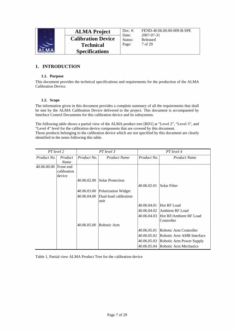
1.2. Scope The information given in this document provides a complete summary of all the requirements that shall be met by the ALMA Calibration Device delivered to the project. This document is accompanied by Interface Control Documents for this calibration device and its subsystems. The following table shows a partial view of the ALMA product tree [RD1] at “Level 2”, “Level 3”, and “Level 4” level for the calibration device components that are covered by this document. Those products belonging to the calibration device which are not specified by this document are clearly identified in the notes following this table.
PT level 2 PT level 3 PT level 4 Product No. Product
Name Product No. Product Name Product No. Product Name
40.06.00.00 Front end calibration device
40.06.02.00 Solar Protection 40.06.02.01 Solar Filter 40.06.03.00 Polarization Widget 40.06.04.00 Dual-load calibration
unit
40.06.04.01 Hot RF Load 40.06.04.02 Ambient RF Load 40.06.04.03 Hot RF/Ambient RF Load
Controller 40.06.05.00 Robotic Arm 40.06.05.01 Robotic Arm Controller 40.06.05.02 Robotic Arm AMB Interface 40.06.05.03 Robotic Arm Power Supply 40.06.05.04 Robotic Arm Mechanics Table 1, Partial view ALMA Product Tree for the calibration device
ALMA Project
Calibration Device Technical
Specifications
Doc. #: FEND-40.06.00.00-009-B-SPE Date: 2007-07-31 Status: Released Page: 8 of 29
Page 8 of 29
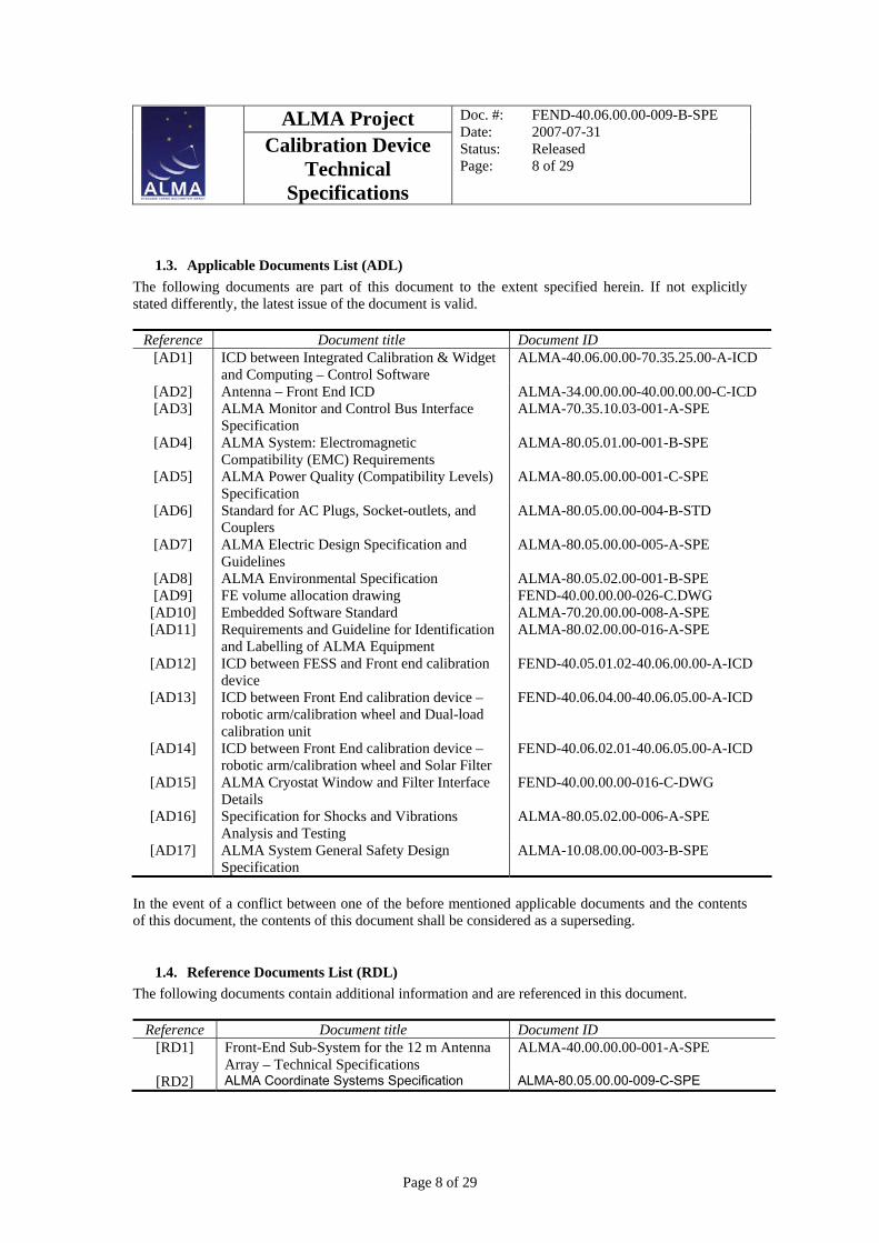
1.3. Applicable Documents List (ADL) The following documents are part of this document to the extent specified herein. If not explicitly stated differently, the latest issue of the document is valid.
Reference Document title Document ID [AD1] ICD between Integrated Calibration & Widget
and Computing – Control Software ALMA-40.06.00.00-70.35.25.00-A-ICD
[AD2] Antenna – Front End ICD ALMA-34.00.00.00-40.00.00.00-C-ICD [AD3] ALMA Monitor and Control Bus Interface
Specification ALMA-70.35.10.03-001-A-SPE
[AD4] ALMA System: Electromagnetic Compatibility (EMC) Requirements
ALMA-80.05.01.00-001-B-SPE
[AD5] ALMA Power Quality (Compatibility Levels) Specification
ALMA-80.05.00.00-001-C-SPE
[AD6] Standard for AC Plugs, Socket-outlets, and Couplers
ALMA-80.05.00.00-004-B-STD
[AD7] ALMA Electric Design Specification and Guidelines
ALMA-80.05.00.00-005-A-SPE
[AD8] ALMA Environmental Specification ALMA-80.05.02.00-001-B-SPE [AD9] FE volume allocation drawing FEND-40.00.00.00-026-C.DWG
[AD10] Embedded Software Standard ALMA-70.20.00.00-008-A-SPE [AD11] Requirements and Guideline for Identification
and Labelling of ALMA Equipment ALMA-80.02.00.00-016-A-SPE
[AD12] ICD between FESS and Front end calibration device
FEND-40.05.01.02-40.06.00.00-A-ICD
[AD13] ICD between Front End calibration device – robotic arm/calibration wheel and Dual-load calibration unit
FEND-40.06.04.00-40.06.05.00-A-ICD
[AD14] ICD between Front End calibration device – robotic arm/calibration wheel and Solar Filter
FEND-40.06.02.01-40.06.05.00-A-ICD
[AD15] ALMA Cryostat Window and Filter Interface Details
FEND-40.00.00.00-016-C-DWG
[AD16] Specification for Shocks and Vibrations Analysis and Testing
ALMA-80.05.02.00-006-A-SPE
[AD17] ALMA System General Safety Design Specification
ALMA-10.08.00.00-003-B-SPE
In the event of a conflict between one of the before mentioned applicable documents and the contents of this document, the contents of this document shall be considered as a superseding.
1.4. Reference Documents List (RDL) The following documents contain additional information and are referenced in this document.
Reference Document title Document ID [RD1] Front-End Sub-System for the 12 m Antenna
Array – Technical Specifications ALMA-40.00.00.00-001-A-SPE
[RD2] ALMA Coordinate Systems Specification ALMA-80.05.00.00-009-C-SPE

ALMA Project
Calibration Device Technical
Specifications
Doc. #: FEND-40.06.00.00-009-B-SPE Date: 2007-07-31 Status: Released Page: 9 of 29
Page 9 of 29
1.5. Acronyms A limited set of basic acronyms used in this document is given below.
ACS Antenna Coordinate System AD Applicable Document ADL Applicable Document List ALMA Atacama Large Millimeter Array AMB ALMA Monitor Bus CAN Controller Area Network CE Communauté Européenne CFCS Cylindrical Front-end Coordinate System EMC Electro Magnetic Compliance FCS ALMA Front-end Coordinate System FE Front End FESS Front End Support Structure ICD Interface Control Document ID Identification IPT Integrated Product Team IR Infra Red RD Reference Document RDL Reference Document List RF Radio Frequency TBC To Be Confirmed TBD To Be Determined WVR Water Vapour Radiometer
1.6. Verb Convention "Shall" is used whenever a specification expresses a provision that is binding. The verbs "should" and "may" express non-mandatory provisions. "Will" is used to express a declaration of purpose on the part of the design activity.
1.7. Requirements Numbering The requirements within the present document are numbered according to the following code:
[FEND-40.06.00.00-XXXXX-YY / Z (ZZ)] Where:
FEND-40.06.00.00 identifies the ‘Front End – Calibration device’ as based on [RD1];
XXXXX is a consecutive number 00010, 00020, (the nine intermediate numbers remaining available for future revisions of this document);
YY describes the requirement revision. It starts with 00 and is incremented by one with every requirement revision;
Z(ZZ) describes the requirement verification method(s). Where T stands for Test, I for Inspection, R for Review of design and A for Analysis. Multiple verification methods are allowed.

ALMA Project
Calibration Device Technical
Specifications
Doc. #: FEND-40.06.00.00-009-B-SPE Date: 2007-07-31 Status: Released Page: 10 of 29
Page 10 of 29
2. DESCRIPTION
2.1. Equipment Definition The calibration device is one of the core components for the ALMA front-end sub-system. It consists of a robotic arm able to position a temperature controlled hot RF load, or an ambient RF load or a solar filter over any of the 10 observing windows or the WVR pick-off mirror. The simultaneous use of a calibration load and the solar filter is not possible.
Figure 2.1, Design Concept of the ALMA calibration device, side view The calibration device will be located in the widget space on top of the FESS.

ALMA Project
Calibration Device Technical
Specifications
Doc. #: FEND-40.06.00.00-009-B-SPE Date: 2007-07-31 Status: Released Page: 11 of 29
Page 11 of 29
Figure 2.2, Design Concept top view of calibration device

ALMA Project
Calibration Device Technical
Specifications
Doc. #: FEND-40.06.00.00-009-B-SPE Date: 2007-07-31 Status: Released Page: 12 of 29
Page 12 of 29
Figure 2.3, Design Concept top view of calibration device in stow position

ALMA Project
Calibration Device Technical
Specifications
Doc. #: FEND-40.06.00.00-009-B-SPE Date: 2007-07-31 Status: Released Page: 13 of 29
Page 13 of 29
2.2. Definition of Coordinate System
For the purpose of discussions and clarification within the specification, the ALMA front-end coordinate system will be used as described in the document ALMA Coordinate Systems Specification [RD2].
The ALMA front-end coordinate system (FCS) is determined as follows. The origin of FCS (0, 0, 0) is located at the intersection of ACS z-axis and nominal antenna focal plane. It has coordinates (0, 0, 803) mm in ACS. The x, y and z axis of FCS are co linear and co oriented with x, y and z orts of ACS respectively. Coordinates can be expressed by vector (X, Y, Z)
Figure 2.4, ALMA antenna coordinate system
It is also convenient to express element locations in cylindrical front-end coordinate system (CFCS) where coordinates can be expressed by (r, φ, z) where r is the distance from z-axis of FCS, φ is the azimuth position and is the same as γr in Figure 3 with φ = 0 is x-axis and z is directly taken from FCS. A short vector notations for position in x-y plane will be used as (x, y) in FCS and (r, φ) in CFCS.

ALMA Project
Calibration Device Technical
Specifications
Doc. #: FEND-40.06.00.00-009-B-SPE Date: 2007-07-31 Status: Released Page: 14 of 29
Page 14 of 29
2.3. Description of the Cryostat layout, windows and IR-filters positions
The cryostat has a diameter of 970 mm and a height of 620 mm. Inside the cryostat there are two radiation shields (110 K and 15 K) inserted into each other. These shields and geometry of the cartridges limits the volume available for cryogenics optics. There are circular apertures (windows and IR-filters) made both in cryostat wall and shields to allow for beam propagation towards cryogenic optics elements.
The receiver band consists of a cartridge, which is fixed to the bottom of the cryostat. The reference plane for cartridges has a FCS (*, *, -620) mm coordinates. The receiver cartridges distribution inside the cryostat is shown in Figure 2.5.
Table 1 gives physical coordinates of each cartridge and the WVR pick-off mirror with respect to the CFCS.
45°
45°band 1
band 2
band 3
band 4
b
band 8
band 9
band 10
x
y
band 5
and 6
band 7
80°
80°
cryocooler
Top view
window
Figure 2.5, ALMA cartridges, cryostat windows and IR filters distribution in FCS x-y plane. The view is from the direction of the telescope secondary mirror.

ALMA Project
Calibration Device Technical
Specifications
Doc. #: FEND-40.06.00.00-009-B-SPE Date: 2007-07-31 Status: Released Page: 15 of 29
Page 15 of 29
CFCS (mm, deg)
X/Y (mm, mm)
300 K Diameter
(mm)
Beam center of M2 above FESS (mm)
CFCS (mm, deg)
X/Y (mm, mm)
Window / warm optics
(mm)
190 mm above FESS
(mm)
600 mm above FESS
(mm)1 31.3 - 45 255, 135º -180.3, 180.3 110 255.00, 135º -180.30, 180.30 180 238 252 2.482 67 - 90 255, -135º -180.3, -180.3 92 246.77, -135º -174.48 -174.48 140 116 183 2.483 84 - 116 310.7, -80º 54, -306 70 110 93 142
3-M2 188, -80º 33, -185 39 183.14, -80º 32.15, -180.22 1.844 125 - 163 310.7, 80º 54, 306 66 120 67 105
4-M2 196, 80º 34, 193 39 190.94 80º 33.12, 188.01 1.925 163 - 211 245, -45º 173.2, -173.2 66 237.09, -45º 167.61, -167.61 75 73 170 2.386 211 - 275 245, 45º 173.2, 173.2 50 237.09, 45º 167.61, 167.61 75 66 165 2.387 275 - 373 100, 0º 100, 0 40 96.77, 0º 96.77, 0 56 69 174 0.978 385 - 500 103.3, -90º 0, -103.3 35 99.96, -90º 0, -99.96 41 66 172 1.019 602 - 720 100, 90º 0, 100 20 96.77, 90º 0, 96.77 27 60 168 0.9710 787 - 950 100, 180º -100, 0 20 96.77, 180º -96.77, 0 21 59 165 0.97
WVR 183 0, 0º 0, 0 0, 0º 0, 0 75 180
Beam Diameter at Angle to Sub-
refl
0
ector (deg)
Beam position at 190 mm above Dewar (2)
Note (1): Band 3 and 4 warm optics mirror M2 location are defined under 3-M2 and 4-M2!Note (2): Beam position for Band 1 at 190 mm above interface plate is same as window position!
Band (1)
Window / Warm optics locations
Freq. (GHz)
Table 1: ALMA frequency bands, cartridges, windows and WVR pick-off mirror mechanical positions and diameters

ALMA Project
Calibration Device Technical
Specifications
Doc. #: FEND-40.06.00.00-009-B-SPE Date: 2007-07-31 Status: Released Page: 16 of 29
Page 16 of 29
3. GENERAL REQUIREMENTS
3.1. Operation Modes The calibration device shall be used according to the following modes. All modes shall apply over the antenna elevation range from 0° to 90°.
3.1.1. Operational This mode is applicable during normal observations with the front end calibration device and its subsystem. For this mode, all specifications and requirements in this document shall apply.
3.1.2. Park position The robotic arm of the calibration device shall be brought to a park position when no calibration or solar observation is done. In the park position no part of the calibration device shall obstruct any receiver beam. In the park position the front end calibration device shall be kept in place by brakes or other means. The park position shall be located in such a way to minimise the time a calibration cycle takes. Different park positions can be used when calibrating different cartridges.
3.1.3. Non-Operational This mode is applicable when the front end calibration device is switched off. Therefore it is also called the “Off-mode”. In the “Off mode” the front end calibration device shall be in its stow position and kept in place by brakes or other means. The stow position shall be located in such a way to minimise the space the calibration device takes inside the widget space. In case of a power failure, the calibration device shall be kept in its current position by brakes or other means. For this mode, the specifications and requirements in all sections of this document shall apply, with the exception of section 4, 5, 6 and unless otherwise noted.
3.1.4. Transport Conditions This mode is applicable when the front end calibration device is switched off and as part of the front end sub-system is transported with the antenna on the antenna transport vehicle. Therefore it is also called the “Transport-mode”. In this mode the front end calibration device shall be in its stow position and kept in place by brakes or other means. For this mode, the specifications and requirements in all sections of this document shall apply, with the exception of section 4, 5, 6 and unless otherwise noted.
3.2. Compatibility with ALMA Front End Sub-System The front end calibration device design shall be compatible with other products within the ALMA front end sub-system. Details as given in the applicable ICD’s [AD2], [AD12], [AD13], [AD14] and [AD15].

ALMA Project
Calibration Device Technical
Specifications
Doc. #: FEND-40.06.00.00-009-B-SPE Date: 2007-07-31 Status: Released Page: 17 of 29
Page 17 of 29
3.3. Design for Production
3.3.1. Technology [FEND-40.06.00.00-00010-00 / R] The front end calibration device design should use mature technologies whenever possible.
3.3.2. Series Production [FEND-40.06.00.00-00020-00 / R] The front end calibration device design should give a high degree of consideration to reduction of production, assembly and operations costs. Complexity of the design and mechanical structures should be simplified wherever possible.
3.3.3. Standard Parts [FEND-40.06.00.00-00030-00 / R] Standard, unmodified commercially available components should be used where possible.
3.4. Cables and Connectors [FEND-40.06.00.00-00040-00 / RI] All AC power cables and connectors shall be in compliance with [AD6] and [AD7]. The AMB connectors shall be in compliance with [AD1].
3.5. Metric Hardware [FEND-40.06.00.00-00050-00 / RI] All hardware used in the calibration device, including but not limited to fasteners, tapped holes, etc., shall be metric. Exceptions shall be coordinated with the FE-IPT.

ALMA Project
Calibration Device Technical
Specifications
Doc. #: FEND-40.06.00.00-009-B-SPE Date: 2007-07-31 Status: Released Page: 18 of 29
Page 18 of 29
4. PERFORMANCE REQUIREMENTS FOR THE CALIBRATION LOADS
4.1. Temperature Requirements for Hot RF Load and Ambient RF Load The calibration device shall have two calibration loads “Hot RF Load” and “Ambient RF Load” according to the following specifications. [FEND-40.06.00.00-00060-00 / R] Each Calibration Load shall be designed as line replaceable units [AD13].
4.1.1. ‘Hot RF Load’ Temperature [FEND-40.06.00.00-00070-00 / T] The hot RF load temperature shall be set in the range between 60 to 100 deg. Celsius.
4.1.2. ‘Hot RF Load’ Temperature Stability [FEND-40.06.00.00-00080-00 / T] The temperature stabilities specified hereafter shall be reached within 1 hour after the calibration device is going from its off-mode or transport-mode to operation-mode. [FEND-40.06.00.00-00090-00 / T] The temperature change of the hot RF load shall be less than 0.2 deg. Celsius on timescales of 100 seconds [TBD].
4.1.3. ‘Hot RF Load’ Thermal Insulation [FEND-40.06.00.00-00095-00 / T] The hot RF load thermal insulation shall be sufficient to cause no increase in temperature of any external part of the hot RF load above 50 deg. Celsius.
4.2. Temperature Sensors [FEND-40.06.00.00-00100-00 / R] The three temperature sensors, one each for the hot RF load and the ambient RF load mentioned in section 4.1. and two additional environmental temperature sensor shall have an accuracy of better than 0.2 deg. Celsius over a temperature range specified in section 4.1.1. and 9.1.2. [FEND-40.06.00.00-00105-00 / R] The temperature sensors for the hot RF load and the ambient RF load mentioned in section 4.1. and the environmental temperature sensor shall have a repeatability of better than 0.1 deg. Celsius over a temperature range specified in section 4.1.1. and 9.1.2.
4.3. RF Requirements for Hot RF Load and Ambient RF Load From [RD1, section 4.4.2] the design goal specification for calibration repeatability for each of the calibration loads shall be better than 1 % for frequencies below 300 GHz and better than 3% for all other frequencies covered by the ALMA Front End.
4.3.1. Frequency Coverage [FEND-40.06.00.00-00110-00 / T] The loads shall be designed for a frequency range from 31.3 GHz to 950 GHz.

ALMA Project
Calibration Device Technical
Specifications
Doc. #: FEND-40.06.00.00-009-B-SPE Date: 2007-07-31 Status: Released Page: 19 of 29
Page 19 of 29
4.3.2. RF Mismatch [FEND-40.06.00.00-00120-00 / T] Return Loss for each of the two calibration loads shall be better than -40 dB across the frequency range specified in section 4.3.1. with the exception for Band 1 (31.3 GHz to 45 GHz) where better than – 30 dB is required.
4.4. Mechanical Requirements for Hot RF Load and Ambient RF Load
4.4.1. Hot RF Load Mass [FEND-40.06.00.00-00130-00 / T] The mass of the hot RF load including the mechanical and electrical interface to the calibration wheel but excluding the controller [ALMA Product Tree 40.06.03.03] shall not exceed 5.0 kg [TBC].
4.4.2. Ambient RF Load Mass [FEND-40.06.00.00-00140-00 / T] The mass of the ambient RF load including the mechanical and electrical interface to the calibration wheel but excluding the controller {ALMA Product Tree 40.06.03.03] shall not exceed 5.0 kg [TBC].
4.4.3. Angular misalignment and repeatability [FEND-40.06.00.00-00145-00 / T] The absolute angular accuracy of any of the two calibration loads relative to the plane of the mechanical interface between FESS and calibration device at any of the position over a observing band and the WVR pick-off mirror shall be less than:
• Angular misalignment: +/- 2.0 mrad [FEND-40.06.00.00-00150-00 / T] The tilt and angular repeatability of any of the two calibration loads relative to the plane of the mechanical interface between FESS and calibration device at any of the position over a observing band and the WVR pick-off mirror shall be less than:
• Angular misalignment: +/- 0.5 mrad [FEND-40.06.00.00-00160-00 / T] The relative angular position stability of any of the calibration loads at any position over an observing band and the WVR pick-off mirror shall be less than:
• Angular position stability: +/- 0.2 mrad
4.4.4. Linear misalignment and repeatability [FEND-40.06.00.00-00170-00 / T] The absolute linear position accuracy and repeatability of the actual centre of any of the calibration loads relative to the centre of the plane of the mechanical interface between FESS and calibration device compared to the nominal position at any of the position over an observing band and the WVR pick-off mirror shall be less than the following values:
• Linear misalignment in horizontal direction : +/- 1.0 mm • Linear misalignment in vertical direction : +/- 1.0 mm
The vertical direction being defined as perpendicular to the plane in which the FESS ring is located. [FEND-40.06.00.00-00180-00 / T] The relative linear position stability of any of the calibration loads at any position over an observing band and the WVR pick-off mirror shall be less than:
• Linear position stability in horizontal direction: +/- 0.2 mm • Linear position stability in vertical direction: +/- 0.1 mm
The vertical direction being defined as perpendicular to the plane in which the FESS ring is located.

ALMA Project
Calibration Device Technical
Specifications
Doc. #: FEND-40.06.00.00-009-B-SPE Date: 2007-07-31 Status: Released Page: 20 of 29
Page 20 of 29
4.5. Time for one calibration cycle and duty cycle [FEND-40.06.00.00-00190-00 / T] One calibration cycle in defined as:
1. Initiated via the AMB bus, move the selected calibration load from its stow or park position over the selected observing band or the WVR pick-off mirror.
2. Stay over the selected band or the WVR pick-off mirror and hold position as specified under 4.4.3. and 4.4.4. until a new command is send via the AMB bus.
3. Initiated via the AMB bus, move the second calibration load over the previously selected observing band or the WVR pick-off mirror.
4. Stay over the selected band or the WVR pick-off mirror and hold position as specified under 4.4.3. and 4.4.4until a new command is send via the AMB bus.
5. Initiated via the AMB bus move the calibration loads back it’s stow or park position.
The total time to move the calibration loads as defined above under 1. 3. and 5. combined shall not exceed 9.0 seconds. [FEND-40.06.00.00-00195-00 / RT] The front end calibration device shall be designed that the above defined calibration cycle could be repeated every 5 minutes.

ALMA Project
Calibration Device Technical
Specifications
Doc. #: FEND-40.06.00.00-009-B-SPE Date: 2007-07-31 Status: Released Page: 21 of 29
Page 21 of 29
5. PERFORMANCE REQUIREMENTS FOR THE SOLAR FILTER
5.1. Solar Filter Requirements The Solar Filter will allow solar observations with ALMA receiver bands 3 to 10. [FEND-40.06.00.00-00200-00 / R] The Solar Filter shall be designed as line replaceable units [AD14].
5.1.1. Frequency Coverage [FEND-40.06.00.00-00210-00 / T] The solar filter shall be designed for a RF frequency range from 84 GHz to 950 GHz.
5.1.2. RF attenuation [FEND-40.06.00.00-00220-00 / T] The RF attenuation across the specified frequency range specified in 5.1.1. shall be 13 – 16 dB.
5.1.3. IR reflection [FEND-40.06.00.00-00230-00 / T] The Solar Filter shall reflect the incoming IR radiation by at least 20 dB. The spectral range for IR reflection is defined as 8 to 15 µm.
5.1.4. RF mismatch [FEND-40.06.00.00-00240-00 / RT] Return Loss for of the Solar Filter for both input and output of the Solar Filter shall be better than -20 dB across the frequency range specified in section 5.1.1.
5.1.5. Cross polarization [FEND-40.06.00.00-00250-00 / RT] The cross polarization induced by the Solar Filter shall be less than -25 dB relative to the co-polar component. This requirement shall be met across the frequency range as specified in section 5.1.1., for both orthogonal polarizations and for any position angle of the Solar Filter.

ALMA Project
Calibration Device Technical
Specifications
Doc. #: FEND-40.06.00.00-009-B-SPE Date: 2007-07-31 Status: Released Page: 22 of 29
Page 22 of 29
5.2. Mechanical Requirements for the solar filter
5.2.1. Solar Filter Mass [FEND-40.06.00.00-00260-00 / T] The mass of the solar filter and its frame shall not exceed 0.5kg [TBC].
5.2.2. Angular misalignment and repeatability [FEND-40.06.00.00-00265-00 / T] The absolute angular accuracy of the solar filter relative to the plane of the mechanical interface between FESS and calibration device at any of the position over a observing band shall be less than:
• Angular misalignment: +/- 2.0 mrad [FEND-40.06.00.00-00270-00 / T] The tilt and angular repeatability of the solar filter relative to the plane of the mechanical interface between FESS and calibration device at any of the position over a observing band shall be less than:
• Angular misalignment: +/- 0.5 mrad [FEND-40.06.00.00-00280-00 / T] The relative angular position stability of any of the calibration loads or the solar filter at any position over a observing band shall be less than:
• Angular position stability: +/- 0.2 mrad
5.2.3. Linear misalignment and repeatability [FEND-40.06.00.00-00290-00 / T] The absolute linear position accuracy and repeatability of the actual centre of the solar filter relative to the centre of the plane of the mechanical interface between FESS and calibration device compared to the nominal position at any of the position over a observing band shall be less than the following values:
• Linear misalignment in horizontal direction : +/- 1.0 mm • Linear misalignment in vertical direction : +/- 1.0 mm
The vertical direction being defined as perpendicular to the plane in which the FESS ring is located. [FEND-40.06.00.00-00300-00 / T] The relative linear position stability of any of the calibration loads or the solar filter at any position over an observing band shall be less than:
• Linear position stability in horizontal direction: +/- 0.2 mm • Linear position stability in vertical direction: +/- 0.1 mm
The vertical direction being defined as perpendicular to the plane in which the FESS ring is located.
5.3. Time to set the solar filter in position [FEND-40.06.00.00-00310-00 / T] The time to move the solar filter from its stow position over a selected observing band and back to its stow position defined as:
1. Initiated via the AMB bus, move the solar filter from its stow position over the selected observing band.
2. Stay over the selected band and hold position as specified under 5.2.2. and 5.2.3. until a new command is send via the AMB bus.
3. Initiated via the AMB bus move the calibration loads back its stow position.
The total time to move the calibration loads as defined above under 1. and 3. combined shall not exceed 7.0 seconds.

ALMA Project
Calibration Device Technical
Specifications
Doc. #: FEND-40.06.00.00-009-B-SPE Date: 2007-07-31 Status: Released Page: 23 of 29
Page 23 of 29
6. PERFORMANCE REQUIREMENTS FOR THE QWP The current Front End Specification [RD1] does not require a QWP anymore. For future upgrade possibilities alignment pins and attachment holes from the two prototypes design shall be kept in place. This is to allow in the future the installation of a linear actuator to move a QWP in front of band 7 window.
6.1. QWP linear actuator installation requirements The QWP shall be moved in front of the band 7 window by means of a linear motor attached to the base of the calibration device. [FEND-40.06.00.00-00320-00 / R] The QWP shall be designed as line replaceable unit [AD15].
6.1.1. Angular misalignment and repeatability [FEND-40.06.00.00-00390-00 / T] The absolute angular accuracy of the QWP in the Z-direction over the band 7 window relative to the plane of the mechanical interface between FESS and calibration device shall be less than:
• Angular misalignment: +/- 2.0 mrad [FEND-40.06.00.00-00400-00 / T] The absolute angle repeatability of the QWP in the Z-direction over the band 7 window relative to the plane of the mechanical interface between FESS and calibration device shall be less than:
• Angular misalignment: +/- 0.2 mrad [FEND-40.06.00.00-00410-00 / T] The relative angular position stability of the QWP over the band 7 window shall be less than:
• Angular position stability: +/- 0.2 mrad
6.1.2. Linear misalignment and repeatability [FEND-40.06.00.00-00420-00 / T] The position and linear repeatability of the actual centre of the QWP relative to the centre of the plane of the mechanical interface between FESS and the QWP compared to the nominal position over the band 7 window shall be less than the following values:
• Linear misalignment in horizontal direction : +/- 1.0 mm • Linear misalignment in vertical direction : +/- 0.5 mm
The vertical direction being defined as perpendicular to the plane in which the FESS ring is located. [FEND-40.06.00.00-00430-00 / T] The relative linear position stability of the QWP over the band 7 window shall be less than:
• Linear position stability in horizontal direction: +/- 0.2 mm • Linear position stability in vertical direction: +/- 0.1 mm
The vertical direction being defined as perpendicular to the plane in which the FESS ring is located.

ALMA Project
Calibration Device Technical
Specifications
Doc. #: FEND-40.06.00.00-009-B-SPE Date: 2007-07-31 Status: Released Page: 24 of 29
Page 24 of 29
7. MECHANICAL REQUIREMENTS
7.1. Mass [FEND-40.06.00.00-00500-00 / I] The total mass of the front end calibration device shall not exceed 75 kg. This mass is the sum of the contributions of all the items that are listed in the ALMA Product Tree under Front end calibration device, (ALMA Prod No.: 40.06.00.00). [FEND-40.06.00.00-00510-00 / I] The total mass of all parts attached to the robotic arm shall not exceed 70 kg. This mass is the sum of: Solar Filter [ALMA Prod No.: 40.06.02.01], Polarization Widget [ALMA Prod No.: 40.06.03.00], Hot RF Load [ALMA Prod No.: 40.06.04.01], Ambient RF Load [ALMA Prod No.: 40.06.04.02], Hot RF Ambient RF Load Controller [ALMA Prod No.: 40.06.04.03] and Robotic Arm Mechanics [ALMA Prod No.: 40.06.05.04]
7.2. Volume [FEND-40.06.00.00-00520-00 / I] The calibration device, mounted in the front end shall be able to fit through the antenna receiver cabin door and shall pass through the opening in the FESS [AD12]. The maximum envelope size of the front end calibration device shall not exceed the space as specified in [AD9].
7.3. Orientation [FEND-40.06.00.00-00530-00 / T] The calibration device shall be designed in such a way that its performance stays in specification over the antenna elevation range from 0° to 90°.
7.4. Eigen Frequency [FEND-40.06.00.00-00540-00 / A] The lowest Eigen frequency of the front end calibration device in any operation mode and at any antenna elevation angle shall be not less than 18 Hz.

ALMA Project
Calibration Device Technical
Specifications
Doc. #: FEND-40.06.00.00-009-B-SPE Date: 2007-07-31 Status: Released Page: 25 of 29
Page 25 of 29
8. ELECTRICAL REQUIREMENTS
8.1. Mains-Power Supply [FEND-40.06.00.00-00550-00 / R] The front end calibration device shall be powered from a 230 VAC power supply. The exact power qualification is described in ALMA Power Quality (Compatibility Levels) Specification [AD5].
8.2. Electrical Power Consumption [FEND-40.06.00.00-00560-00 / T] The front end calibration device (ALMA Prod No.: 40.06.00.00) shall in average not consume more than 250 VA of mains-power. [FEND-40.06.00.00-00565-00 / T] The peak power consumption at any time shall be limited to 450 VA of mains-power.
8.3. EMC Requirements [FEND-40.06.00.00-00570-00 / T] The front end calibration device and its components as described in 1.2 of this document, shall comply with requirements as specified in [AD4].

ALMA Project
Calibration Device Technical
Specifications
Doc. #: FEND-40.06.00.00-009-B-SPE Date: 2007-07-31 Status: Released Page: 26 of 29
Page 26 of 29
9. ENVIRONMENTAL OPERATING CONDITIONS
9.1. Operational conditions
9.1.1. Altitude [FEND-40.06.00.00-00580-00 / R] The front end calibration device and its sub systems shall operate at an altitude from 0 to 5200 m.
9.1.2. Operating Temperature [FEND-40.06.00.00-00590-00 / T] The front end calibration device and its sub systems shall operate at a temperature range of 10 o C to 25o C with a temperature stability of +/- 2 o C per hour of its nominal value.
9.1.3. Relative Humidity [FEND-40.06.00.00-00600-00 / R] The front end calibration device shall operate at a relative humidity range according to [AD8, section 5.7] this being 0 % to 95 %.
9.1.4. Vibration [FEND-40.06.00.00-00610-00 / A] The front end calibration device shall survive vibration levels as specified in [AD8, Section 8.2.8 and in Appendix 1 and AD16].
9.1.5. Acceleration [FEND-40.06.00.00-00620-00 / A] The front end calibration device shall comply with the following survival specification:
• 4 g shock load in the vertical direction • 3 g shock load in any horizontal direction
The vertical direction is defined as perpendicular to the plane in which the FESS ring is located.
9.2. Surface Finish [FEND-40.06.00.00-00630-00 / R] The front end calibration device including all sub systems as defined in section 1.2 of this document, shall have an appropriate surface finish to prevent corrosion.
9.3. Storage and Shipping Conditions [FEND-40.06.00.00-00635-00 / R] The front end calibration device including all sub systems as defined in section 1.2 of this document, shall comply with [AD8, Section 8].

ALMA Project
Calibration Device Technical
Specifications
Doc. #: FEND-40.06.00.00-009-B-SPE Date: 2007-07-31 Status: Released Page: 27 of 29
Page 27 of 29
10. FUNCTIONAL REQUIREMENTS
10.1. Monitoring and Control The front end calibration device is controlled from the ALMA computing control software via the front end monitoring and control subsystem a CAN bus node [AD1]. The control functions include the insertion of a calibration load or solar filter into the antenna beam for a certain cartridge. The monitor functions are used to observe and log the status and conditions of the device.
10.1.1. Remotely Controlled Functions [FEND-40.06.00.00-00640-00 / R] The following components shall be electronically controlled and in compliance with [AD1]:
• Reset and initialize calibration device • Set calibration load/solar filter to X, Y position • Move calibration device to its stow position • Insert or remove calibration load • Set the temperature of the hot RF load • Insert or remove the solar filter
10.1.2. Monitoring Points [FEND-40.06.00.00-00650-00 / R] The following parameters shall be monitored with appropriate sensors and in compliance with [AD1]:
• Obtain the position of the hot RF load • Obtain the position of the ambient RF load • Obtain the temperature of the hot RF load • Obtain the set point temperature of the hot RF load • Obtain the temperature of the ambient RF load • Obtain the calibration device environmental temperature • Obtain the position of the solar filter • Obtain an electronic ID chip number

ALMA Project
Calibration Device Technical
Specifications
Doc. #: FEND-40.06.00.00-009-B-SPE Date: 2007-07-31 Status: Released Page: 28 of 29
Page 28 of 29
11. RAMS REQUIREMENTS
11.1. Continuous Operation [FEND-40.06.00.00-00660-00 / R] The front end calibration device shall be designed for continuous use.
11.2. Reliability [FEND-40.06.00.00-00670-00 / R] Repeated calibration cycling of the front end calibration device structural components, including hot RF load and ambient RF load, solar filter etc., shall not cause catastrophic system failure. The front end calibration device shall be designed for not less than 500000 calibration cycles.
11.3. Lifetime [FEND-40.06.00.00-00680-00 / R] The calibration device shall have the same minimum lifetime as the front end sub-system, this being 15 years.
11.4. Maintainability [FEND-40.06.00.00-00690-00 / R] The calibration device shall have a regular service interval of not less than 3 years. The regular scheduled servicing shall be limited to mechanical components.

ALMA Project
Calibration Device Technical
Specifications
Doc. #: FEND-40.06.00.00-009-B-SPE Date: 2007-07-31 Status: Released Page: 29 of 29
Page 29 of 29
11.5. Safety
11.5.1. Handling [FEND-40.06.00.00-00700-00 / R] The calibration device and its components having a mass of over 25 kilograms shall have the provision of attaching suitable lifting eyes to enable handling with a hoist.
11.5.2. Electrical [FEND-40.06.00.00-00710-00 / R] All electrical parts used in the calibration device shall comply with CE safety standards.
11.5.3. Power Failure [FEND-40.06.00.00-00720-00 / T] In case of a power failure, the calibration device shall be kept in its current position by brakes or other means.
11.5.4. Moving Parts [FEND-40.06.00.00-00730-00 / R] All moving and rotating parts of the calibration device shall be properly shielded, equivalent to applicable CE rules, to avoid injury.
11.5.5. Hot Surfaces [FEND-40.06.00.00-00740-00 / R] All heated parts of the calibration device shall be properly shielded, equivalent to applicable CE rules, to avoid injury.
11.5.6. Protective Earth [FEND-40.06.00.00-00750-00 / R] A protective earth point shall be provided and clearly marked as such [AD7].
11.5.7. Fail Safe [FEND-40.06.00.00-00760-00 / R] The design of the calibration device shall be such that no damage to the Windows and warm mirrors can occur in the case of a malfunction of the calibration device.