Embed Size (px)
Citation preview

CD-09/20/05 – COOL’05
Cryogenics for theCryogenics for the MuCoolMuCool Test Area (MTA) Test Area (MTA) C. Darve, B. Norris, L. Pei
Fermi National Accelerator LaboratoryBatavia, IL, 60500, USA
COOL’05 – Galena, IL
Headlines
ScopeHelium FacilityHydrogen FacilityApplications 1) Past: Convection LH2 absorber2) Present: SC Solenoid magnet3) Future: Forced-flow LH2 absorber, (Convection run 2)

CD-09/20/05 – COOL’05
Cryogenic Cooling for Ionization Cooling
The MTA is a Fermilab test facility constructed to support new The MTA is a Fermilab test facility constructed to support new developments in the physics and engineering ofdevelopments in the physics and engineering of muonmuon beam cooling beam cooling
MTA cryo-engineering requirements
Ø Design, prototype and bench test cooling-channel components
§ Provide helium and nitrogen refrigeration
§ Provide liquid hydrogen
§ Install equipment, instrumentation, DAQ & control in compliance with Fermilab safety policy (ES&H)
Important reference and guidelineFERMILAB: “ Guidelines for the Design, Fabrication, Testing, Installation and Operation of LH2 Targets – 20 May 1997” by Del Allspach et al. Fermilab RD_ESH_010– 20 May 1997
NASA: “ SAFETY STANDARD FOR HYDROGEN AND HYDROGEN SYSTEMS: Guidelines for Hydrogen System Design, Materials Selection, Operations, Storage, and Transportation”
Previous US H2 experiments : E158, SAMPLE, G0, Fermilab hydrogen experts
CD-09/20/05 – COOL’05
Cryogenic Cooling for Ionization Cooling
ApplicationsApplications- LH2 Absorbers:
• Convection scheme (<100W?) - MICE design• Forced-flow scheme (up to 300W) - MuCool design
– S.C. solenoid magnet for RF cavity test (long term: LH2 absorber)– Other applications using HP gaseous hydrogen : Muon Inc.
Proposed cooling channel test bench

CD-09/20/05 – COOL’05
R
nn
LmEEds
dE
dsd
µµµ
µ ββ
εβ
ε2
)014.0(11 2
32⊥+−=
Bethe-Bloch multiple scattering
21 ZLR
αAZa
dxdE
Ionization cooling
Ionization & Cryogenic Materials
CEC 30 August 2005 Paper C1-J-03 2
Cryogenic Properties of Various Gasses
Parameter He N 2 H 2 CH 4 C 3H 8
Triple point temperature T t (K) 2.177^ 63.15 13.81* 90.69 91.46Heat of fusion @ T t (J g -1) -NA- 25.3 59.5* 58.41 79.97Boiling temp. T b @ 1 bar (K) 4.222 77.35 20.28* 111.67 230.46Liquid density ρ l @ T b (kg m -3) 124.9 807 70.8* 422.4 585.3Gas density ρg @ T b (kg m -3) 16.89 4.622 1.339* 1.816 2.497Gas to liquid volume ratio at T b 7.395 175.6 52.87* 232.6 298.0Gas V 293 to Liquid V b Ratio 699.4 645.6 792.9 591.4 379.0Gas C p @ T b (J g -1 K -1) 9.144 1.341 12.24* 2.218 1.642Heat of vaporization @ T b (J g -1) 20.7 198.8 445* 510.8 424.8Heat flux for ∆T=300-T b (kWm -2) ~200 ~27 ~93 ~47 -NA-Broken vacuum heat flux (kWm -2) ~35 ~1.6 ~19 ~0.31 -NA-Critical temperature T c (K) 5.195 126.2 32.98 190.6 368.8Critical pressure P c ( MPa) 0.228 3.39 1.29 4.59 4.36
^ The lambda point temperature for helium. For helium liquid, gas, and solid can’t coexist.* This data is for para hydrogen. Ortho hydrogen changes to para hydrogen at < 100 K.
M. Green: “Hydrogen Safety Issues compared to Safety Issues with Methane and Propane”, CEC’05

CD-09/20/05 – COOL’05
Ionization & Cryogenic Materials
Parameter H2 CH4 C3H8
Flammability limits in air (%) 4.0 - 74.2 5.0 – 15.0 2.1 – 9.4Ignition temperature in air (K) ~855 ~925 ~770Ignition energy @ STP (J/cc) ~0.74 ~0.97 ~0.76Stoichiometric flame temperature in air (K) ~2580 ~2340 ~2390Heat of combustion (kJ g -1) 135.4 52.8 40.3Liquid heat of combustion (MJ per liter) 9.59 22.29 23.56Gas heat of combustion (MJ m -3 @ STP) 12.09 37.70 93.48Temp when gas is heavier than RT air (K) ~21 ~162 ~444
Source: NASA, Glenn Research Center Safety Manual

CD-09/20/05 – COOL’05
Cryogenic Systems for MTA Solenoid Magnet
From concept…
To reality...

CD-09/20/05 – COOL’05
Tevatron-style Satellite Refrigerator
2 x Compressor set
Nitrogen tank
Helium storage tankHeat exchanger
Purification skid
Transfer lines to experimental hall
Dry engine
Wet engine
Wet engine
bayonet can
Dry engine
500 liters portable LHe Dewars

CD-09/20/05 – COOL’05
Installation of 300 KW Screw Compressors
Aftercooler
CoalescersOil vapor contamination from helium gas is further removed through the outdoors purification skid

CD-09/20/05 – COOL’05
SC solenoid magnet
LH2 forced-flow cryostat
Refrigeration Modes
liquefier mode
14 K mode
Capacity is 550 W at 14K

CD-09/20/05 – COOL’05
The MTA Process and Control System
Functions and Mandates:
ü Monitor and control operations - Reliability
ü Activate alarms for out-of-limits and hazardous conditions - Reliability
ü Collect data for performance studies (complementary to users DAQ) - Accuracy
- Audio and visual alarms
- Crash buttons
- Annunciators
- Interlocks
Safety equipment:
- Flammable gas detectors
-ODH detectors
- FIRUS system
- Building ventilation
- Flow switch

CD-09/20/05 – COOL’05
Siemens-Moore QUADLOGTM
Integrated safety features for a failIntegrated safety features for a fail--safe safe PLCPLC
Fault tolerance
Self-testing software
Decreased start-up time and minimized downtime with online diagnostics and detailed error reporting
Easier integration with other control systems via open communications
Ø Monitoring and automated response to pre-defined scenarios
è Combines the beneficial features of a PLC (modularity, ladder logic and sequential programming, high-speed logic solving, and industrial strength) with high safety, high availability, and extensive diagnostics
è QUADLOGTM incorporates continuous PID control, analog I/O and a variety of operator interface options not typically available from a PLC

CD-09/20/05 – COOL’05
PLC Modules
SAM: Standard Analog Module Pressure TransducersHeaterElectro-valve
SDM: Standard Discrete ModuleEV, Pump, ODH, FIRUSLH2 absorber liquid level too lowH2 presence in the absorber statusPurge cabinet statusAudio system statusEmergency answer status (SD progress)FIRUS (ODH and H2)Interlocks status
CDM: Critical Discrete ModuleOxygen Deficiency Hazard (x4)Flammable gas detectors (x3)He cool-down start statusSystem stop statusSystem reset status
VIM: Voltage Input ModuleLevel, Pressure, Flow, Temp. (Pt-co)
RTM: Resistance Temperature ModulePlatinum and carbon temperature sensors

CD-09/20/05 – COOL’05
Modified Tevatron Cryogenic Control

CD-09/20/05 – COOL’05
Mandates from Fermilab and Engineering Solutions
1) Need QUADLOG® Safety PLC for monitoring and automated response to pre-defined scenarios (hydrogen leak, vacuum rise, person entering interlocked room)
2) Establish a large set of procedural controls and written operating procedures3) Meet NEC standards for Class I, Div 2, Group B, (Class I = hazard; Div 2 =
hazard sometimes present;Group B = hydrogen) 4) Establish nitrogen purge box to meet NEC standards; contained ignition sources
not meeting code5) Build intrinsically safe barriers6) All cabling using MC type or PLTC cable7) Used H2 gas detectors located in the experimental hall and in the gas manifold
room for automated response8) Use Excess flow valve on hydrogen gas fill line9) Provide ‘secondary containment’ and use buffer tank on vacuum volume10)Limit the MAWP of hydrogen vessel to 0.16 MPa
Note: Equipment @ Refrigerator: conventional Tevatron devices è DirectLogic PLC

CD-09/20/05 – COOL’05
Application 1: KEK convection-type LH2 Absorber Process and Instrumentation

CD-09/20/05 – COOL’05
Application 1: KEK convection-type LH2 Absorber Process and Instrumentation

CD-09/20/05 – COOL’05
Application 1: KEK convection-type LH2 Absorber Installation and Results
Platinum Cobalt temperature sensorsElement: platinum-cobalt diffused alloyTemperature Range: 4K – 375K (R800-6)Resistance at 0 C: 100 Ohm +/- 0.15 OhmPermissible Range: +/- 0.5K Repeatability: less than 10mKMeasurement Current: 2mA
6.2 liters of LH2
0 .0
0 .5
1.0
1.5
2 .0
2 .5
3 .0
0 4 8 12 16 20 2 4Heat load to the LH2 absorber (W)
Tem
per
atu
re g
rad
ien
t (K
)19 .5 K
18 .4 K
16 .3 K
18 K
16 .4 K
18 .8 K
15 .4 K
15 .1 K15
15.5
16
16.5
17
17.5
18
18.5
19
19.5
20
TC-10
6-H
TC-10
7-H
TC-10
8-H
TC-10
9-H
TC-11
0-H
TC-11
1-H
TC-11
2-H
TC-11
3-H
Sensor distribution
Te
mp
era
ture
(K
)
Q=0 Watt
Q=12.4 Watt
Q=23.7 Watt
Q=18.7 Watt
Some results - summer 2004 test campaign
@ LH2 : T=16.3 K ; P=0.15 MPa

CD-09/20/05 – COOL’05
Application 1: KEK convection-type LH2 Absorber Installation and Results
An upgrade would be needed to better quantify LH2 absorber performance with longer term tests under stable cooling conditions
• More heat deposed
èShorten transfer line to optimize helium usage/reduce heat load
• HTC improperly measured
èImmersed helium temperature sensors; remove warm helium heater and use electrical heater (KEK design: sheathed cartridge inserted in finned aluminum exchanger; temperature monitoring for auto-ignition concerns)
• Improve instrumentation
è Cernox thermometry, use liquid level probe for LH2 bath
Ref: CEC’05 paper - A. Bross et. al, “An upgrade for the MuCool Test Area”, submitted to Cryogenic Engineering Conference 2005, CEC’05
CD-09/20/05 – COOL’05
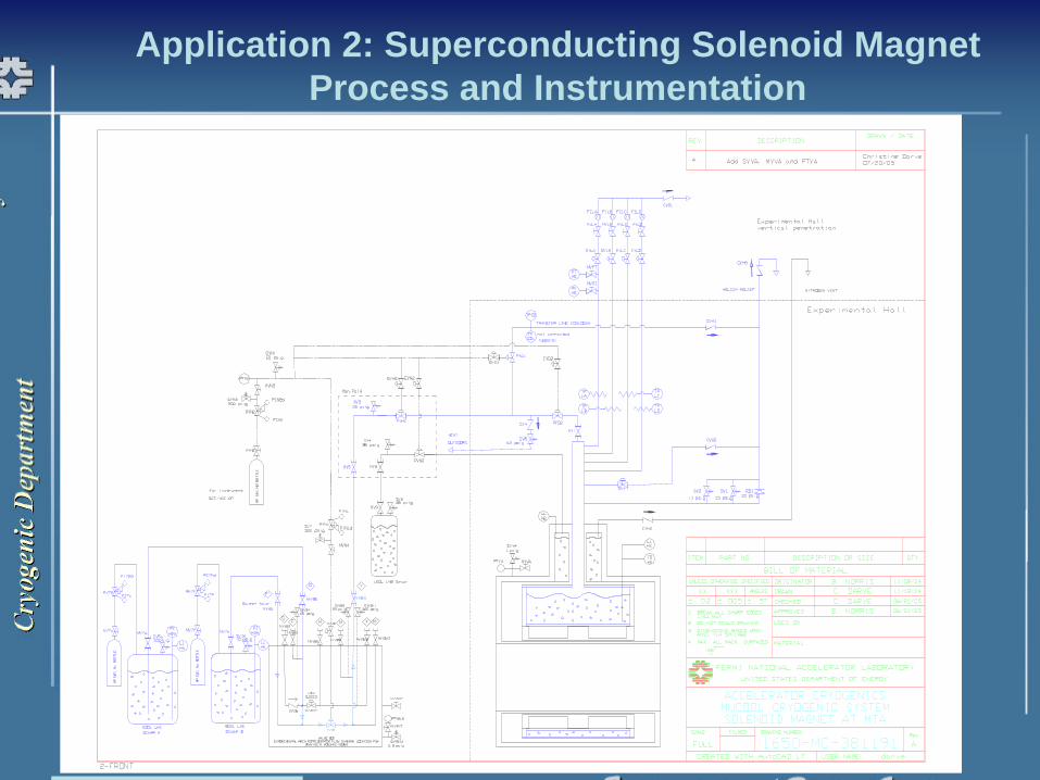
Application 2: Superconducting Solenoid MagnetProcess and Instrumentation
CD-09/20/05 – COOL’05
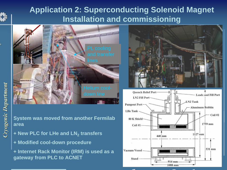
Application 2: Superconducting Solenoid MagnetInstallation and commissioning
Helium cool-down line
PL cooling and transfer lines
System was moved from another Fermilab area
+ New PLC for LHe and LN2 transfers
+ Modified cool-down procedure
+ Internet Rack Monitor (IRM) is used as a gateway from PLC to ACNET
CD-09/20/05 – COOL’05
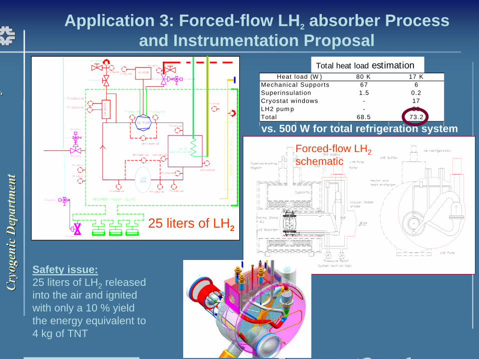
Application 3: Forced-flow LH2 absorber Process and Instrumentation Proposal
25 liters of LH2
80 K 17 K67 6
Superinsulation 1.5 0.2Cryostat windows - 17LH2 pum p - 50Total 68.5 73.2
Heat load (W )Mechanical Supports
Total heat load estimation
vs. 500 W for total refrigeration system
Safety issue: 25 liters of LH2 released into the air and ignited with only a 10 % yield the energy equivalent to4 kg of TNT
Forced-flow LH2schematic

CD-09/20/05 – COOL’05
Application 3: Forced-flow LH2 Absorber 3-D Conceptual Design
Reference papers:
C. Darve et al., “The Liquid Hydrogen System for the MuCool Test Area”, CEC’03, 2003
C. Darve et al., “Cryogenic Design for a Liquid Hydrogen Absorber System”, ICEC19, 2002
LH2 loop and vacuum vessel-Structural study-Thermal study- Hydraulic study (in collaboration with Oxford Univ.)
-Safety Review Documents
Modified to account for the SAMPLE cryostat?
CD-09/20/05 – COOL’05
Concluding comments
On-going cryogenic efforts at MTA
Ø Hydrogen facility was successfully designed, built and commissioned at Fermilab
Ø Helium facility (compressor, refrigerator and transfer line) is under fabrication to complete the final infrastructure
Ø Temporary infrastructure has permitted to test the LH2 convection absorber in summer 2004
Ø SC solenoid magnet cooling system is installed
Ø Forced-flow LH2 absorber design must be completedMTA “deliverables” shall prove the feasibility of ionization cooling but also the practicality of cryogenic cooling in hazardous environment
èMTA = Fermilab facility fully equipped with cryogenic capacity (Hydrogen and Helium)