Embed Size (px)
Citation preview
Cryogenics for Neutral Beam Injector System
Ch. Chakrapani, S.K.Sharma, A.K.Chakraborty, B.Sridhar, Vishnu .B. Patel, Siddharth Sheth, N.V.M.Rao, Mainak. B, G.B.Patel, M.J.SinghJanardhan.U, S.Rambabu, S.K.Mattoo, &NBI team
Institute for Plasma Research, Bhat, Gandhinagar, 382428.
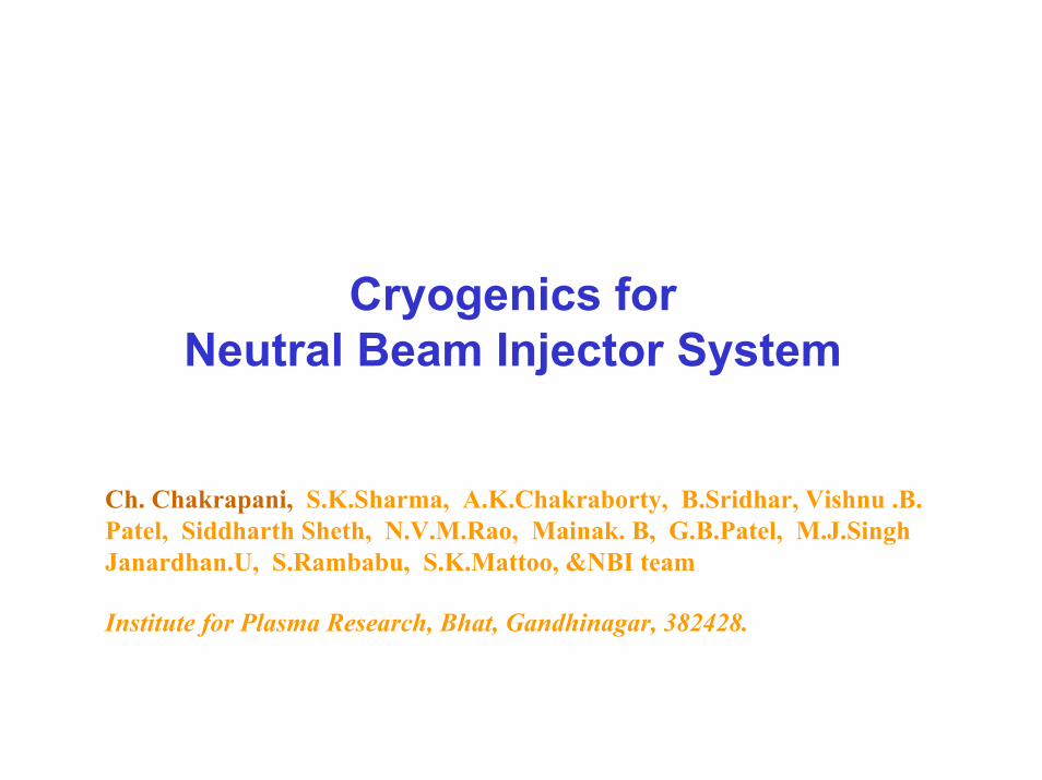
DUCT SIDE
ELEVATION
NEUTRAL BEAM INJECTION SYSTEM
ION SOURCE SIDETOP VIEW
1
2NEUTRAL BEAM
INJECTOR AT IPR
Parameter ValueInjectionInjected PowerDelivered PowerBeam Voltage (kV)SpeciesEstimated temp.rise (keV)No. of beam linesNo. of sourcesReliability
CO, tangential5 MW1.7 MW20-80Ho, Do, He~1
11>75% of shots of0.5 MW and 1.7MW

3-D VIEW OF THE VARIOUS COMPONENTS
IN THE INJECTOR BOX

Need of Cryogenics for NBI:• To handle high throughputs of H2/D2 (50-100 torr l/s)• To maintain back ground pressure of 10-5 torr over a beam line of
~6m
High pumping speed requirement of 106 l/s
Solution: In-Vessel Cryopumps

NBI CRYO PLANT:
Gas Management
Helium Refrigerator Load
Utilities
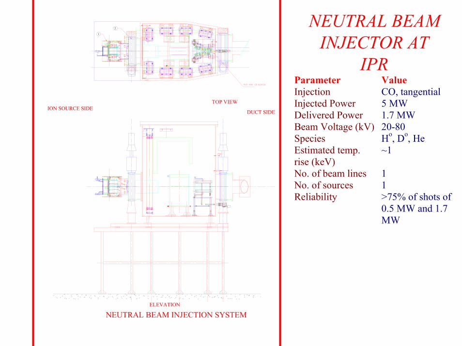
Load: Cryopumps
Helium Refrigerator: Compressor, Cold box, Dewar, Valve box, Transfer lines, etc.
Gas Management: Buffer tank, recovery tank, gas bags
Utilities: LN2 distribution system, Air, Water, Electricity
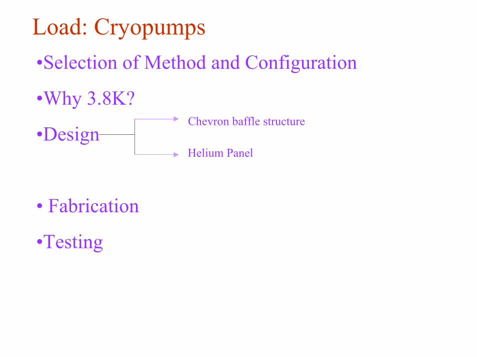
Load: Cryopumps•Selection of Method and Configuration
•Why 3.8K?
•Design
• Fabrication
•Testing
Chevron baffle structure
Helium Panel

Method & Configuration selection:• Cryoadsorption- Regeneration after short pulses• Cryocondensation- Regeneration after long pulses-Suitable
for 1000s Steady state operation.- Open type (JET type) or Chevron type
Open type- very high speed and high heat loads
Chevron type- High speed and low heat loads- Suitable for NBI
Why 3.8K?•3.8K or 4.2K- 4.2K for high back ground pressure ( ⇒low
vacuum insulation) operation. 3.8K for low back ground pressure operation
below 5 X 10⁻⁶ torr surrounding Helium panel(10-5 torr in the chamber).

Design of Cryopumps1. Chevron baffle parameters2. Helium panel parameters

OFHC copper3100 x 550 x 263 2101Al2O3 + TiO2 (60:40) (Plasma spray)
SS304 L2600 x 330 1Silver coated (Electrochemical Brush coating technique)Formed and resistance welded
SS304L seamless pipes
G-10 cryogenic grade3100 x 600 x 300
Chevron BafflesBase materialDimension (mm)NumberThickness(mm)CoatingLHe panelMaterialDimensions (mm)Thickness (mm)Coating
Manufacturing technology
DistributorsMaterialSupportsOverall pump dimensions (mm)
ValueParameter
Monte Carlo simulationParameter Values
Baffle width (cm) 2.9
Angle (deg.) 120
Inter baffle spacing (cm) 1.3
Bounce parameterParticle transmissivityPhoton transmissivity
50.231.3 x 10-3
Reflectivity of Helium panel: 0.95
Emissivity of Chevron baffle: 0.9
The design parameters lead to a pumping speed of ~10 l/s/cm2 for hydrogen, with the panel at 3.8 K, and ~ 7 l/s/cm2 for Deuterium, with the panel is cooled to temperatures ~ 4.2 K.

Fabrication of Cryopumps1) Chevron baffles: a) Cu to SS TIG Brazing b) Black coating
2) Helium panel : a) SS sheets stich welding b)Silver plating

Black Coated Chevron baffle
TIG brazing jointsHelium Panel
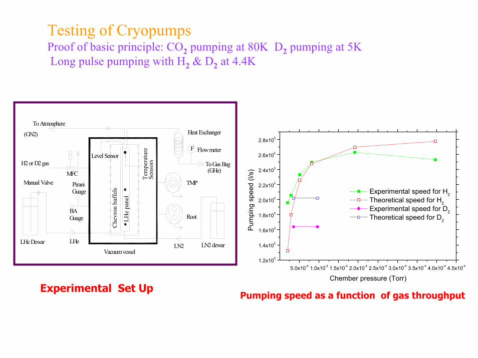
Testing of CryopumpsProof of basic principle: CO2 pumping at 80K D2 pumping at 5KLong pulse pumping with H2 & D2 at 4.4K
5.0x10⁻⁵ 1.0x10⁻⁴ 1.5x10⁻⁴ 2.0x10⁻⁴ 2.5x10⁻⁴ 3.0x10⁻⁴ 3.5x10⁻⁴ 4.0x10⁻⁴ 4.5x10-41.2x105
1.4x10⁵
1.6x10⁵
1.8x10⁵
2.0x10⁵
2.2x10⁵
2.4x10⁵
2.6x10⁵
2.8x10⁵
Experimental speed for H2 Theoretical speed for H2 Experimental speed for D2 Theoretical speed for D2
Pum
ping
spe
ed (l
/s)
Chember pressure (Torr)
F
MFC
H2 or D2 gas To Gas Bag
F
Heat Exchanger
Flow meter
Che
vron
baf
fels
LHe
pane
l
LN2 dewarLHe Dewar
To Atmosphere
Tem
pera
ture
Se
nsor
s
Vacuum vessel
(GHe)
(GN2)
TMP
Root
Level Sensor
LN2 LHe
PiraniGuage
BA Guage
Manual Valve
Pumping speed as a function of gas throughputExperimental Set Up

Helium Refrigerator
•Estimation of Heat loads
•Method for achieving 3.8K
•Process Design
•Process Calculations
•Fabrication of equipment & Delivery
•Erection & Installation
•Commissioning

Heat loads at 3.8K:•Load on 10 Cryopumps 60W •Distribution load 50W
Helium Refrigerator capacity-- 110W at 3.8K

Method for 3.8K:- Vacuum Screw compressor for Creating sub
atmospheric pressure
- Additional sub-atmospheric heat exchanger for
utilising cold enthalpy from the load

Process Design:
COLD BOXCOMPRESSOR
DEWARVALVE BOX
SUBATMHX
VSC
CRYOPUMPS
NBMP
NBRT
FROM SCMS MPSS
COOLDOWN LINE
NBI HELIUM REFRIGERATOR PLANT
MAIN
TO GAS BAG
TO GAS BAG
TO GAS BAGTO GAS BAG
OIL REMOVAL
OIL REMOVAL

cryo pumps
T1
HELIUM VESSEL
COOL DOWN LINE
RETURN LINE
L1
Return Header
Inlet Header
V3
V4V6
V7
V2
V9
V5
(0.6 bar, 3.7K) Rupture disc(7barg)
T
Temperature
Vacuum Screw
REFRIGERATOR SYSTEM
Medium pressure storage system
Cold Box
Main
Compressor
Main Dewar (1.3bar, 4.5K)
V10
Gas bag
HeaterV11VT2VT1
VR1
VR2
Return Header
Return Header
Inlet Header
cryo pumps
L1 T1
NORMAL MODE
TEST STAND MODE
V8
VALVE BOX
cryo pumps
cryo pumps
(Vacuum vessel)
(Vacuum vessel)
V12
Injector box
Test Stand
SS Recovery tank
Oil removalsystem
V13
V14
V1
compressor
PSV 3barg
Sub. Atm. Hx.
V15
PSV 19barg sensor

Process Calculations- Process Calculation note
- 110W at 3.8K with out LN2 precooling- ~170W with LN2 precooling
HELIUM REFRIGERATOR PLANT:
STANDARD HELIAL1000 + CUSTOMISED COMPONENTS FROM M/s AIRLIQUIDE-DTA
STANDARD HELIAL1000;1) MAIN COMPRESSOR WITH OIL REMOVAL SYTEM2) COLD BOXCUSTOMISED COMPONENTS:
1) DEWAR
2) VALVE BOX
3) SUB ATMOSPHERIC HEAT EXCHANGER
4) VACUUM SCREW COMPRESORS WITH OIL REMOVAL SYSTEM

-Sizing of Components:1) 8g/s at 0.6bar to 1.5 bar Vacuum Screw compressor
2) Valve box with 40 l LHe phase separator Vessel
3) Sub atmospheric Heat exchanger for utilising cold enthalpy of return gas
4) 1500l main Dewar
5) 60m3 at 14 bar Carbon steel (CS) buffer tank and 15m3 at 6bar Stainless Steel (SS) recovery tank-Gas management
-Process and Instrumentation Diagram-PID:
- Internal details of individual equipment
- process routing
- Valve size and location
- Instrument type and location
-Pipe/tube sizes
- Safety device locations
-External interfaces of individual components (Cold box, valve box, Dewar, etc.)

-Thermo-Siphon Calculation:Thermo-siphon flow design -- 20g/s with 20mm inlet dia and 25 mm outlet dia for 20m line length of inlet and out lines

Return Header
Inlet header
LHe Phase Separator Vessel
Cryopump
LIQUID HELIUM DISTRIBUTION SCHEME FOR CRYOPUMPS
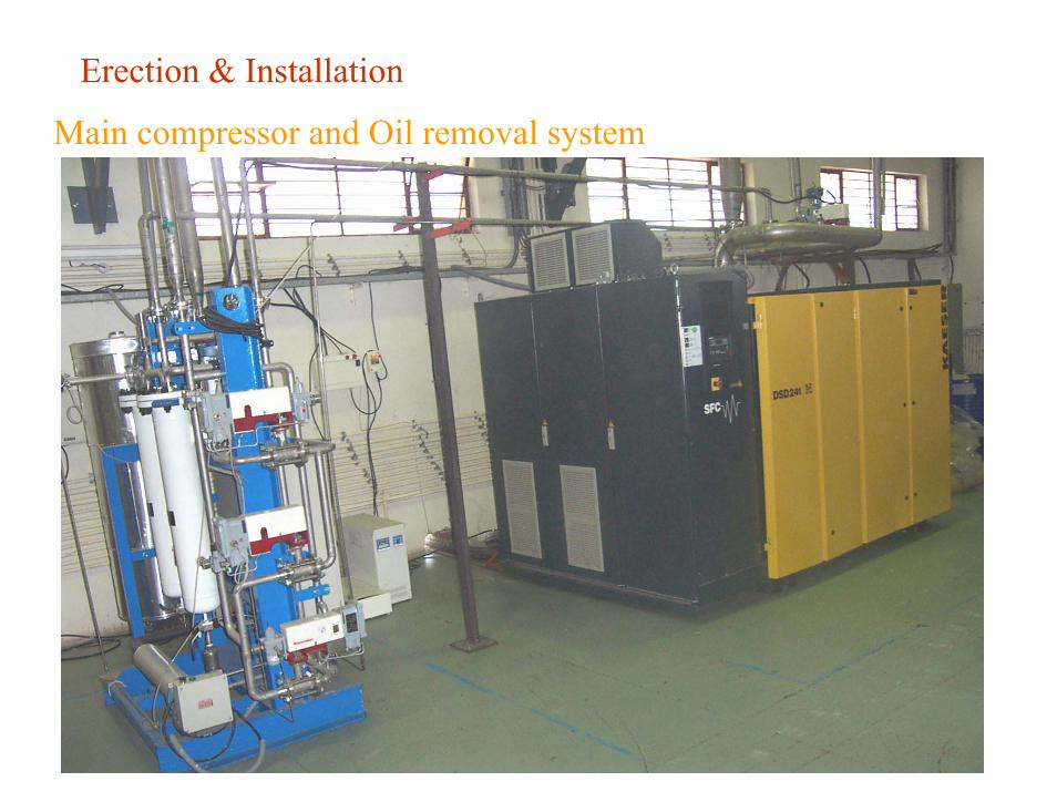
Erection & Installation
Main compressor and Oil removal system


Main Compressor- Rotary Screw Compressor with Variable frequency drive 40g/s- inlet 1.05 bar – Outlet 14bar

Main compressor Oil removal System

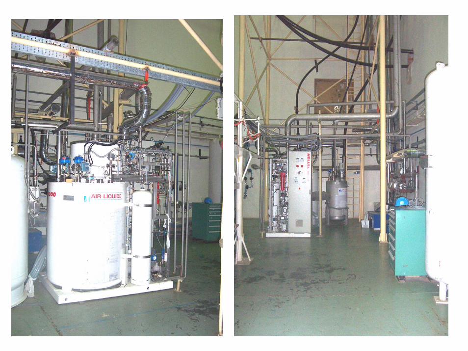
Cold box
Cold box and Main Dewar (1500l)

Sub-atmospheric Heat exchanger

Oil removal system for Vacuum Screw Compressor

Vacuum Screw Compressor- 8g/s (<300K at inlet) 0.6 bar to 1.5bar
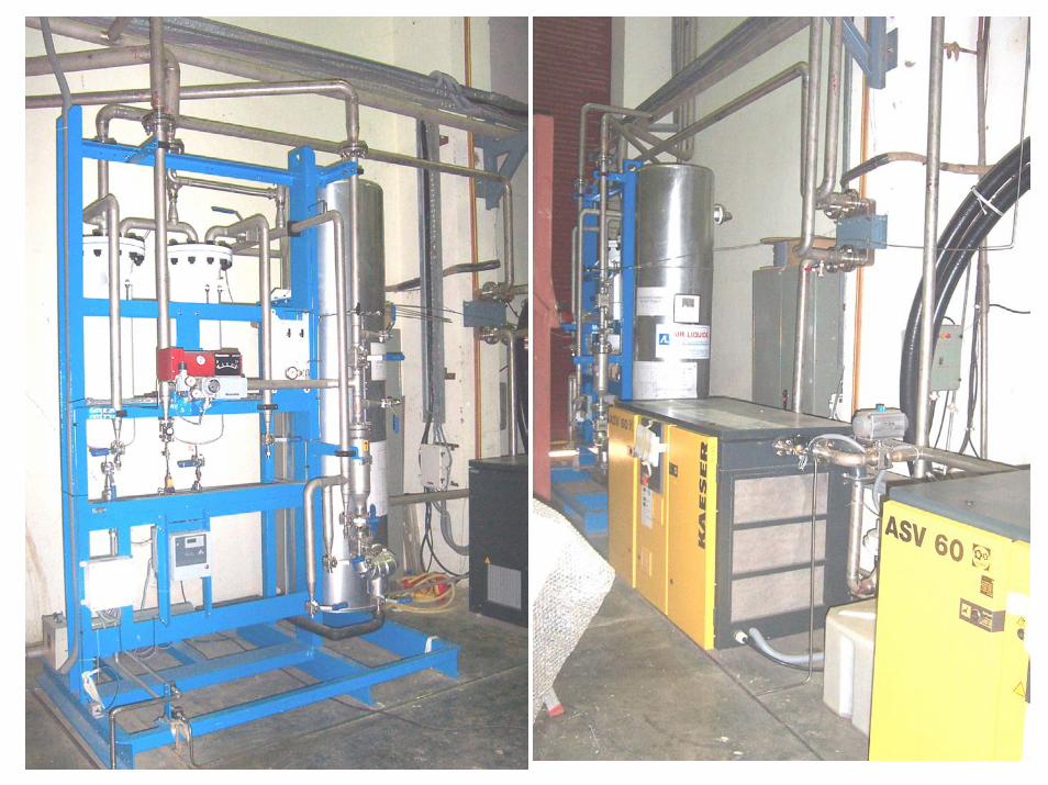

Control panel
VALVE BOX WITH 40l PHASE SEPARATOR VESSEL


DRAIN
CRYO HALL
EXISTING WATERBRIDGE


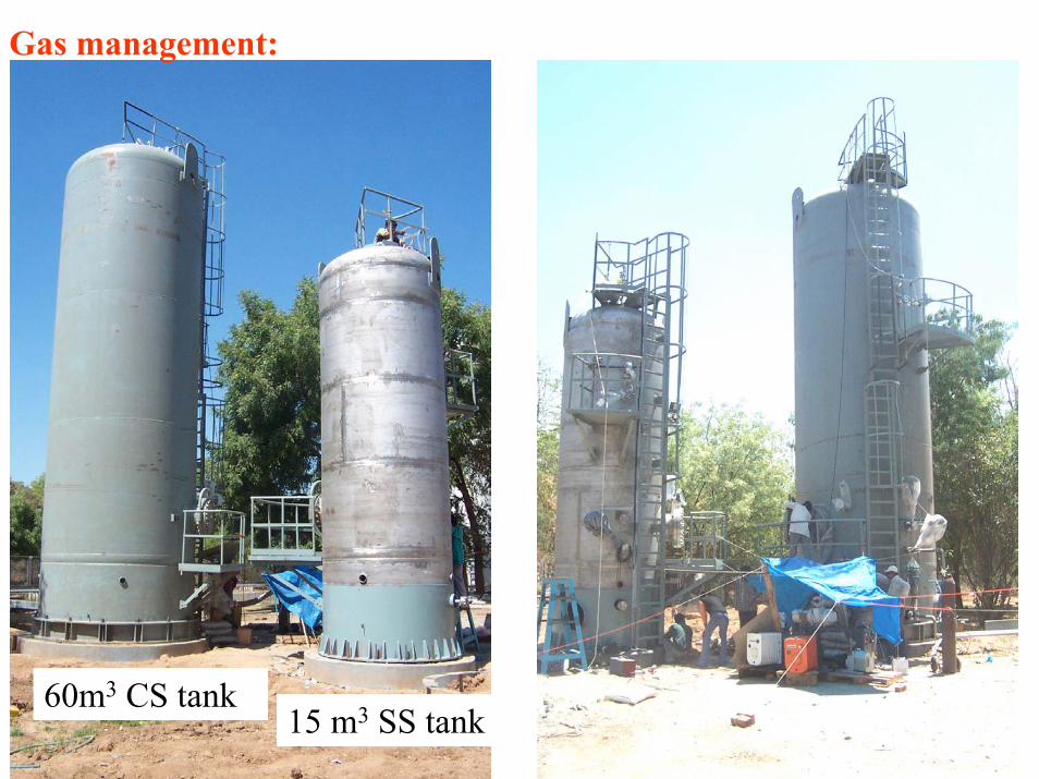
Gas management:
15 m3 SS tank60m3 CS tank

NRV
NRV
MV
FE
PSV
FCV
FCV
PI
LI
TI
FEFCV
PHASE SEPARATOR DEWAR (1000L)
PI
MV
APPL-I
APPL-II
APPL-III
PRV
LIQUID NITROGEN FROMMAIN TANKS (250 l/hr)
TO VENT
SCHEMATIC OF LIQUID NITROGEN DISTRIBUTION SYSTEM
FCV - FLOW CONTROL VALVE PSV - PRESSURE RELIEF VALVE NRV- NON RETURN VALVE LI - LEVEL INDICATOR
MV- MANUAL VALVE FE- FLOW METER PI- PRESSURE INDICATOR TI - TEMPERATURE INDICATOR
(1.9 bar, ~83K)
Liquid Nitrogen System:Average consumption 250l/hr, beam on period 1050 l/hr, beam off period 200l/hr


Present status:1. 10 cryopumps are ready for operation2. Successful installation of all the components of the plant
and Piping3. Commissioning;
a) Conditioning of cold box and valve boxb) Main compressor start up and PID loops checkingc) Cooldown procedure start up
4. Installation of CS and SS tanks is under progress5. Prototype distribution headers for 3 Cryopumps are under testing

Proto-type LN2 shielded LHe distribution header for 3 Cryopumps:

Major Issues during Plant erection, installation and commissioning
•Erection of support structure for valve box
•Valve box installation on the support structure
•Handling and erection of Helium transfer lines
•Calibration of Valves
•Conditioning of 2Km SS pipelines
•PLC programming debugging
• Main compressor start up
•Starting up of turbines
•Vacuum Screw compressor start up
•Vacuum testing of Carbon steel tank

CONCLUSION:• Indigenously built large scale Cryo-condensation pumps
are available for NBI system operation. • The design for the in-vessel LHe distribution system for
the 10 cryopumps has been done by IPR . • Prototypes for inlet and return headers for 3 pumps are
under testing. • The LN2 lines with control and safety valves between
main distribution system and loads have been fabricated in-house.
• Carbon steel buffer tank and SS recovery tank are erected and vacuum tests are under progress.
• All the GHe piping work and instrumentation work required for the Helium Refrigerator system has been prepared by IPR.
• The expected date of completion of Helium refrigerator system commissioning with all the components integrated is mid July 2006