Embed Size (px)
Citation preview
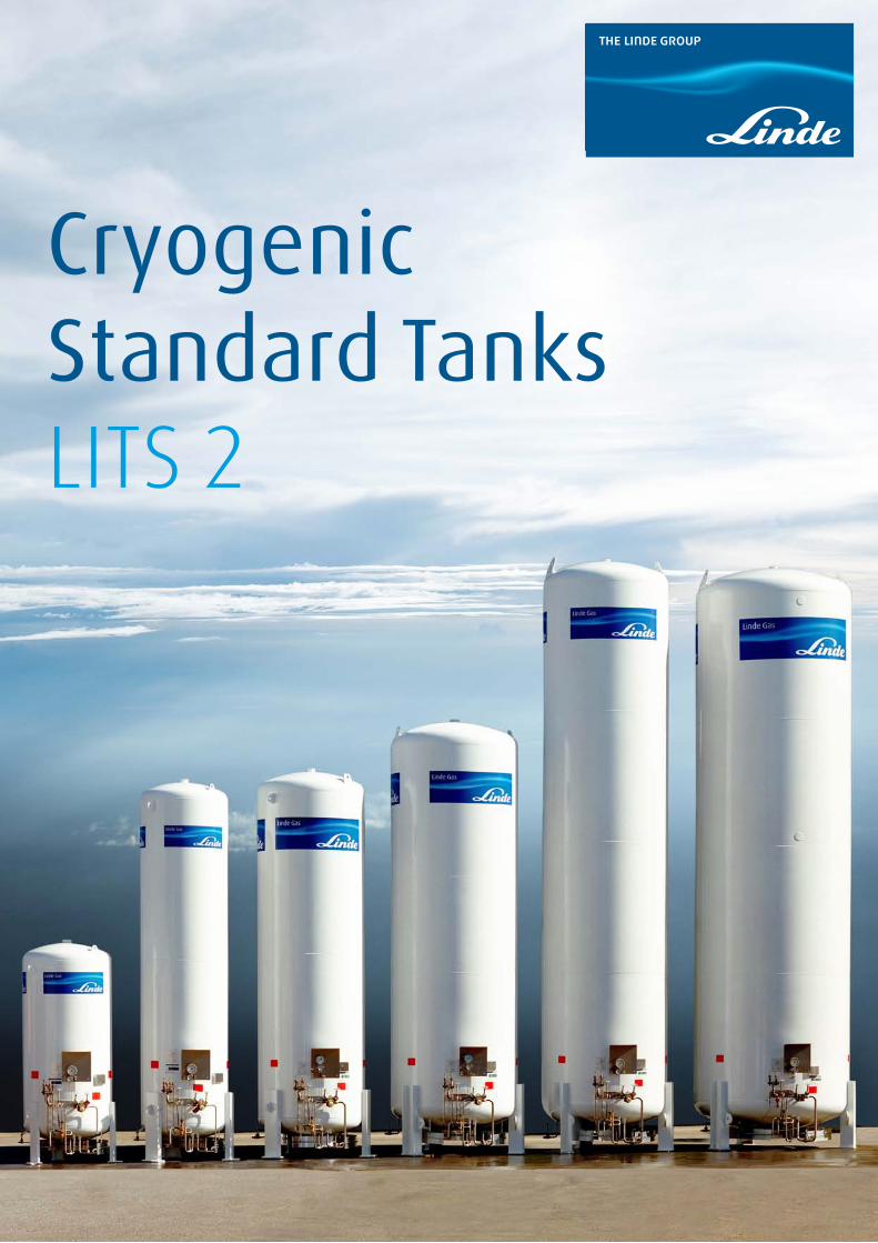
Cryogenic Standard TanksLITS 2
Title-page: The Linde standard tanks
2
3 Introduction
4 Standard vacuum-insulated tanks
5 Quality standards for cryogenic tanks
Optional standards for enhanced quality
6 Technical data - tanks for air gases LIN, LOX, LAR
7 Technical data - tanks for carbon dioxide
8 Features
Highly effective operation
Easy operation
Safety
Ergonomical position of controls and instruments
Non-corroding transport and lifting devices
10 Flow diagram - tanks for nitrogen, oxygen, argon
11 Flow diagram - tanks for carbon dioxide
12 Clip-on standard design
Special VAP - Quality for specific use
14 SHEQ - safety, health, environment and quality police
15 Service and guarantee
16 Contact
Product range
Contents.

3
To an increasing extent, industrial gases such as oxygen, nitrogen and argon are delivered to custo-mers in liquid form at cryogenic temperatures and stored by the customer in tanks before further use.
The pressure ratings and sizes of these tanks have been standardised in accordance with the require-ments of distribution logistics and economical series production.
3
Introduction.
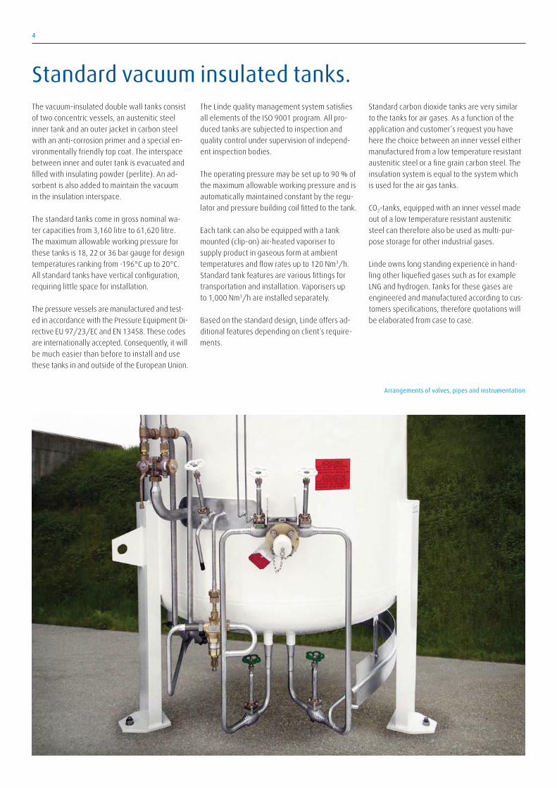
Arrangements of valves, pipes and instrumentation
The vacuum-insulated double wall tanks consist
of two concentric vessels, an austenitic steel
inner tank and an outer jacket in carbon steel
with an anti-corrosion primer and a special en-
vironmentally friendly top coat. The interspace
between inner and outer tank is evacuated and
filled with insulating powder (perlite). An ad-
sorbent is also added to maintain the vacuum
in the insulation interspace.
The standard tanks come in gross nominal wa-
ter capacities from 3,160 litre to 61,620 litre.
The maximum allowable working pressure for
these tanks is 18, 22 or 36 bar gauge for design
temperatures ranking from -196°C up to 20°C.
All standard tanks have vertical configuration,
requiring little space for installation.
The pressure vessels are manufactured and test-
ed in accordance with the Pressure Equipment Di-
rective EU 97/23/EC and EN 13458. These codes
are internationally accepted. Consequently, it will
be much easier than before to install and use
these tanks in and outside of the European Union.
The Linde quality management system satisfies
all elements of the ISO 9001 program. All pro-
duced tanks are subjected to inspection and
quality control under supervision of independ-
ent inspection bodies.
The operating pressure may be set up to 90 % of
the maximum allowable working pressure and is
automatically maintained constant by the regu-
lator and pressure building coil fitted to the tank.
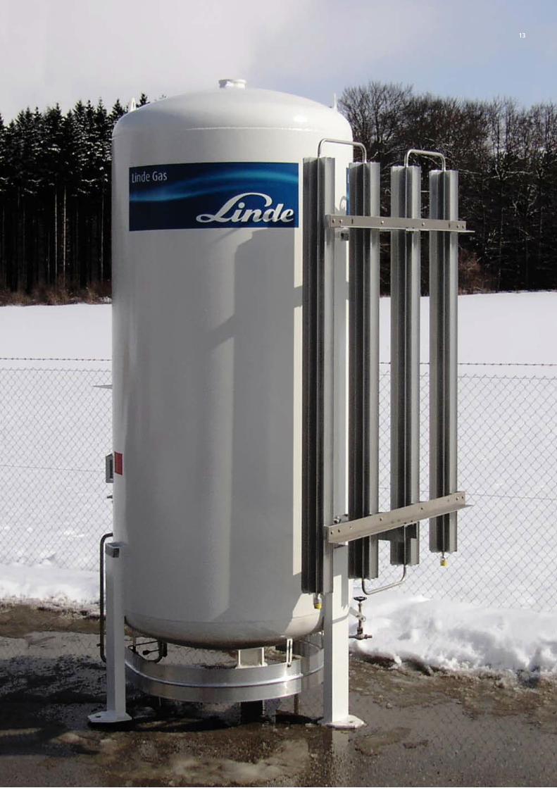
Each tank can also be equipped with a tank
mounted (clip-on) air-heated vaporiser to
supply product in gaseous form at ambient
temperatures and flow rates up to 120 Nm3/h.
Standard tank features are various fittings for
transportation and installation. Vaporisers up
to 1,000 Nm3/h are installed separately.
Based on the standard design, Linde offers ad-
ditional features depending on client´s require-
ments.
Standard carbon dioxide tanks are very similar
to the tanks for air gases. As a function of the
application and customer’s request you have
here the choice between an inner vessel either
manufactured from a low temperature resistant
austenitic steel or a fine grain carbon steel. The
insulation system is equal to the system which
is used for the air gas tanks.
CO2-tanks, equipped with an inner vessel made
out of a low temperature resistant austenitic
steel can therefore also be used as multi-pur-
pose storage for other industrial gases.
Linde owns long standing experience in hand-
ling other liquefied gases such as for example
LNG and hydrogen. Tanks for these gases are
engineered and manufactured according to cus-
tomers specifications, therefore quotations will
be elaborated from case to case.
4
Standard vacuum insulated tanks.
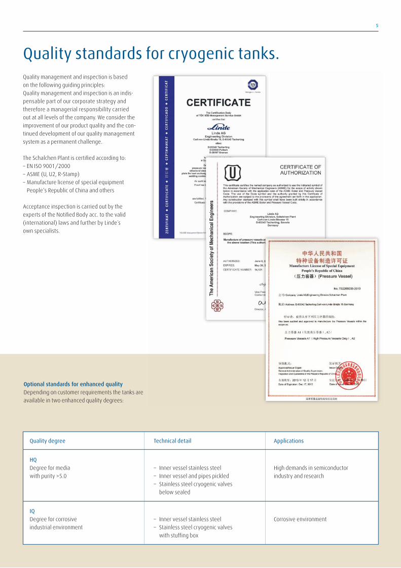
Quality management and inspection is based
on the following guiding principles:
Quality management and inspection is an indis-
pensable part of our corporate strategy and
therefore a managerial responsibility carried
out at all levels of the company. We consider the
improvement of our product quality and the con-
tinued development of our quality management
system as a permanent challenge.
The Schalchen Plant is certified according to:
– EN ISO 9001/2000
– ASME (U, U2, R-Stamp)
– Manufacture license of special equipment
People‘s Republic of China and others
Acceptance inspection is carried out by the
experts of the Notified Body acc. to the valid
(international) laws and further by Linde´s
own specialists.
5
Quality standards for cryogenic tanks.
Optional standards for enhanced qualityDepending on customer requirements the tanks are
available in two enhanced quality degrees:
Quality degree Technical detail Applications
HQ
Degree for media – Inner vessel stainless steel High demands in semiconductor
with purity >5.0 – Inner vessel and pipes pickled industry and research
– Stainless steel cryogenic valves
below sealed
IQ
Degree for corrosive – Inner vessel stainless steel Corrosive environment
industrial environment – Stainless steel cryogenic valves
with stuffing box
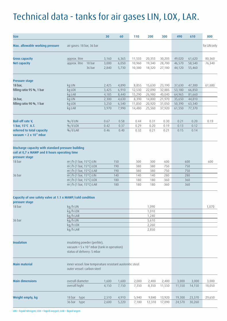
Technical data - tanks for air gases LIN, LOX, LAR.
Size 30 60 110 200 300 490 610 800
Max. allowable working pressure air gases: 18 bar, 36 bar for LIN only
Gross capacity approx. litre 3,160 6,365 11,535 20,355 30,205 49,020 61,620 80,360
Net capacity approx. litre 18 bar 3,000 6,050 10,960 19,340 28,700 46,570 58,540 76,340
36 bar 2,840 5,730 10,380 18,320 27,180 44,120 55,460
Pressure stage18 bar, kg LIN 2,425 4,890 8,855 15,630 23,190 37,630 47,300 61,680
filling ratio 95 %, 1 bar kg LOX 3,425 6,910 12,530 22,090 32,885 53,180 66,850
kg LAR 4,185 8,440 15,290 26,980 40,040 64,965 81,660
36 bar, kg LIN 2,300 4,630 8,390 14,800 21,970 35,650 44,810
filling ratio 90 %, 1 bar kg LOX 3,250 6,540 11,850 20,920 31,050 50,390 63,340
kg LAR 3,970 7,990 14,480 25,560 37,920 61,550 77,370
Boil-off rate V, %/d LIN 0.67 0.58 0.44 0.31 0.30 0.21 0.20 0.19
1 bar, 15°C A.T. %/d LOX 0.42 0.37 0.29 0.20 0.19 0.13 0.12
referred to total capacity %/d LAR 0.46 0.40 0.32 0.21 0.21 0.15 0.14
vacuum < 2 x 10⁻² mbar
Discharge capacity with standard pressure buildingcoil at 0,7 x MAWP and 8 hours operating timepressure stage
18 bar m3/h (1 bar, 15°C) LIN 150 300 300 600 600 600
m3/h (1 bar, 15°C) LOX 190 380 380 750 750
m3/h (1 bar, 15°C) LAR 190 380 380 750 750
36 bar m3/h (1 bar, 15°C) LIN 140 140 140 280 280
m3/h (1 bar, 15°C) LOX 180 180 180 360 360
m3/h (1 bar, 15°C) LAR 180 180 180 360 360
Capacity of one safety valve at 1.1 x MAWP/cold conditionpressure stage18 bar kg/h LIN 1,090 1,070
kg/h LOX 1,010
kg/h LAR 1,240
36 bar kg/h LIN 5,610
kg/h LOX 2,260
kg/h LAR 2,850
Insulation insulating powder (perlite),
vacuum < 5 x 10⁻² mbar (tank in operation)
status of delivery: 5 mbar
Main material inner vessel: low temperature resistant austenitic steel
outer vessel: carbon steel
Main dimensions overall diameter 1,600 1,600 2,000 2,400 2,400 3,000 3,000 3,000
overall hight 4,150 7,150 7,350 8,350 11,550 11,550 14,150 18,050
Weight empty, kg 18 bar type 2,510 4,910 5,940 9,840 13,920 19,300 23,370 29,650
36 bar type 2,600 5,220 7,180 12,310 17,090 24,570 30,260
LIN = liquid nitrogen; LOX = liquid oxygen; LAR = liquid argon

Technical data - tanks for carbon dioxide.
Size 30 60 110 200 300 490 610
Max. allowable CO2 : 22 bar
working pressure
Gross capacity approx. litre 3,160 6,365 11,535 20,355 30,205 49,020 61,620
Net capacity approx. litre 2,940 5,920 10,730 18,930 28,090 45,590 57,310
Filling ratio 93 %, 1 bar kg CO2 3,120 6,280 11,370 20,065 29,780 48,330 60,740
Boil-off rate V, 1 bar, 15°C A.T. %/d CO2 0.22 0.19 0.14 0.10 0.10 0.07 0.06
referred to total capacity vacuum < 2 x 10⁻² mbar
Discharge capacity with standardpressure building coil at 0.7 x MAWPand 8 hours operating time
pressure stage
22 bar kg/h (1 bar, 15°C) CO2 70 140 140 280 280
Capacity of one safety valveat 1.1 x MAWP/cold condition
pressure stage22 bar kg/h, CO2 975
Insulation insulating powder (perlite),
vacuum < 5 x 10⁻² mbar (tank in operation)
status of delivery: 5 mbar
Main material inner vessel: low temp. resistant austenitic steel
outer vessel: carbon steel
Main dimensions overall diameter 1,600 1,600 2,000 2,400 2,400 3,000 3,000
overall hight 4,150 7,150 7,350 8,350 11,550 11,550 14,150
Weight empty, kg 22 bar Type 2,510 4,910 6,300 10,250 14,500 20,500 24,800
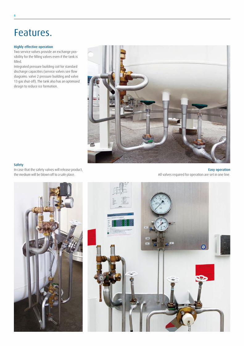
Highly effective operationTwo service valves provide an exchange pos-
sibility for the filling valves even if the tank is
filled.
Integrated pressure building coil for standard
discharge capacities (service valves see flow
diagrams: valve 2 pressure building and valve
13 gas shut-off). The tank also has an optimized
design to reduce ice formation.
Easy operationAll valves required for operation are set in one line.
SafetyIn case that the safety valves will release product,
the medium will be blown off to a safe place.
Features.
8
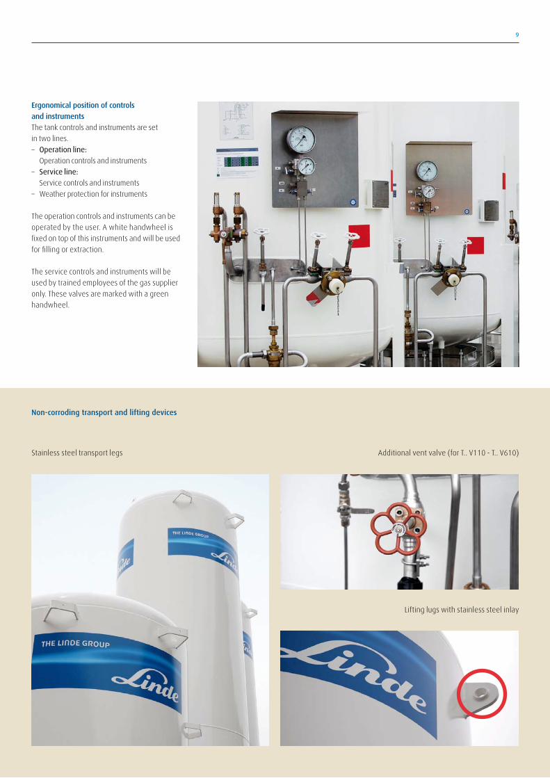
Ergonomical position of controlsand instrumentsThe tank controls and instruments are set
in two lines.
– Operation line:
Operation controls and instruments
– Service line:
Service controls and instruments
– Weather protection for instruments
The operation controls and instruments can be
operated by the user. A white handwheel is
fixed on top of this instruments and will be used
for filling or extraction.
The service controls and instruments will be
used by trained employees of the gas supplier
only. These valves are marked with a green
handwheel.
Non-corroding transport and lifting devices
9
Additional vent valve (for T.. V110 - T.. V610)
Lifting lugs with stainless steel inlay
Stainless steel transport legs
Instrumentation and equipment, standard
C/1 Fill coupling
C/4, C/6 Connection add. transmitter
C/PI Test connection pressure indicator
D Pressure building coil
I Inner vessel
IN Insulation
LI Level indicator
L/11-1 Pipeline discharge
L/11-2 Pipeline discharge (plugged)
L/11-3 Pipeline discharge (plugged)
NRV Non return valve
O Outer vessel
PC Pressure controller
PI Pressure indicator
RV/O Relief valve-outer vessel
SV1, SV2 Safety valve
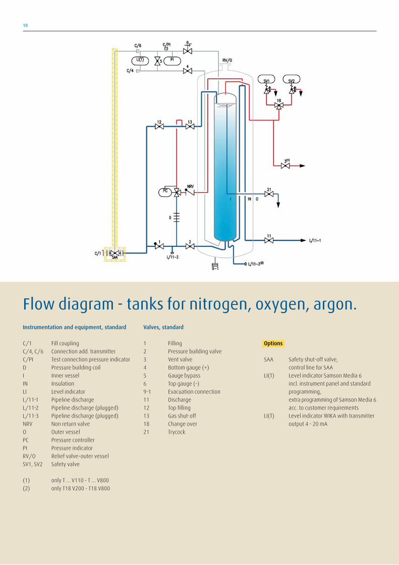
(1) only T ... V110 - T ... V800
(2) only T18 V200 - T18 V800
Valves, standard
1 Filling
2 Pressure building valve
3 Vent valve
4 Bottom gauge (+)
5 Gauge bypass
6 Top gauge (-)
9-1 Evacuation connection
11 Discharge
12 Top filling
13 Gas shut-off
18 Change over
21 Trycock
Options
SAA Safety shut-off valve,
control line for SAA
LI(T) Level indicator Samson Media 6
incl. instrument panel and standard
programming,
extra programming of Samson Media 6
acc. to customer requirements
LI(T) Level indicator WIKA with transmitter
output 4 - 20 mA
Flow diagram - tanks for nitrogen, oxygen, argon.
10

Instrumentation and equipment, standard
C/3 Vent coupling
C/4, C/6 Connection add. transmitter
C/PI Test connection pressure indicator
D Pressure building coil
I Inner vessel
IN Insulation
LI(T) Level indicator
L/11-1 Pipeline discharge
L/11-2 Pipeline discharge (plugged)
NRV Non return valve
O Outer vessel
PC Pressure controller
PI Pressure indicator
RV/O Relief valve-outer vessel
SV1, SV2 Safety valve
Valves, standard
1 Filling
2 Pressure building valve
3 Vent
4 Bottom gauge (+)
5 Gauge bypass
6 Top gauge (-)
9-1 Evacuation connection
11 Discharge
12 Top filling
13 Gas shut-off
18 Change over
21 Trycock
26 Pressuring
Options
SAA Safety shut-off valve,
control line for SAA
LI(T) Level indicator Samson Media 6
incl. instrument panel and standard
programming,
extra programming of Samson Media 6
acc. to customer requirements
LI(T) Level indicator WIKA with transmitter
output 4 - 20 mA
Flow diagramm - tanks for carbon dioxide.
11
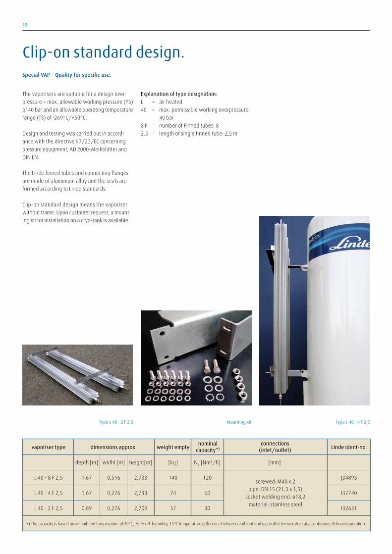
12
The vaporisers are suitable for a design over-
pressure = max. allowable working pressure (PS)
of 40 bar and an allowable operating temperature
range (TS) of -269°C/+50°C.
Design and testing was carried out in accord-
ance with the directive 97/23/EC concerning
pressure equipment, AD 2000-Merkblätter and
DIN EN.
The Linde finned tubes and connecting flanges
are made of aluminium alloy and the seals are
formed according to Linde Standards.
Clip-on standard design means the vaporiser
without frame. Upon customer request, a mount-
ing kit for installation on a cryo-tank is available.
Explanation of type designation:
L = air heated
40 = max. permissible working overpressure:
40 bar
8 F = number of Finned tubes: 8
2,5 = length of single finned tube: 2,5 m
Type L 40 - 2 F 2,5
vaporiser type dimensions approx. weight empty Linde ident-no.
depth [m] widht [m] height[m] [kg] N2 [Nm³/h] [mm]
L 40 - 8 F 2,5 1,67 0,516 2,733 140 120 J34895
L 40 - 4 F 2,5 1,67 0,276 2,733 74 60 I32740
L 40 - 2 F 2,5 0,69 0,276 2,709 37 30 I32631
*) The capacity is based on an ambient temperature of 20°C, 70 % rel. humidity, 15°C temperature difference between ambient and gas outlet temperature at a continuous 8-hours-operation
screwed: M40 x 2pipe: DN 15 (21,3 x 1,5)
socket welding end: ø18,2material: stainless steel
nominalcapacity*)
connections(inlet/outlet)
Type L 40 - 4 F 2,5Mounting kit
Special VAP - Quality for specific use.
Clip-on standard design.
13
14
At the Engineering Division, we do not want to
harm people or the environment. We will com-
ply with all applicable legal, regulatory, internal
and industry requirements.
We strive to be leading in SHEQ to meet safe,
secure and healthy working conditions and
supplying safe, compliant and environmentally
responsible products and services for our
customers.
SHEQ is a key part of The Linde Group’s overall
strategy and we will also require our contractors
and partners to manage in line with this policy.
SHEQ - safety, health, environment and quality police.
To achieve this vision,SHEQ is 100 % of our
behaviour,100 % of the time.
15
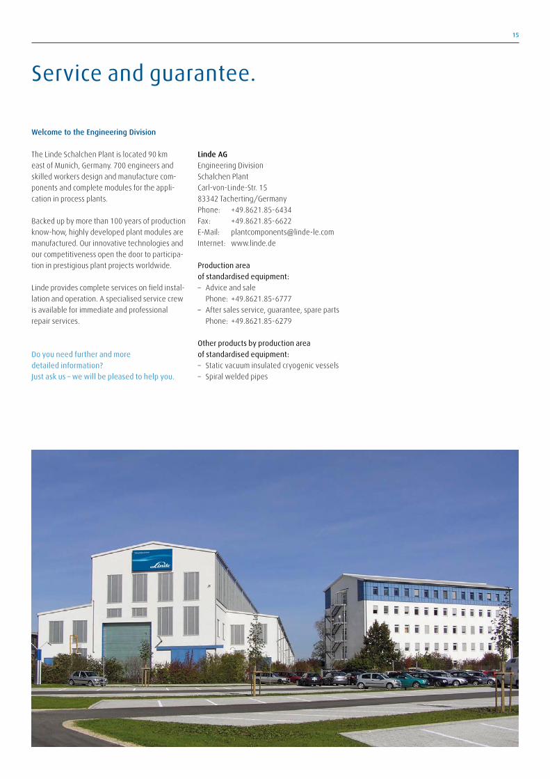
Welcome to the Engineering Division
The Linde Schalchen Plant is located 90 km
east of Munich, Germany. 700 engineers and
skilled workers design and manufacture com-
ponents and complete modules for the appli-
cation in process plants.
Backed up by more than 100 years of production
know-how, highly developed plant modules are
manufactured. Our innovative technologies and
our competitiveness open the door to participa-
tion in prestigious plant projects worldwide.
Linde provides complete services on field instal-
lation and operation. A specialised service crew
is available for immediate and professional
repair services.
Do you need further and more
detailed information?
Just ask us – we will be pleased to help you.
Linde AGEngineering Division
Schalchen Plant
Carl-von-Linde-Str. 15
83342 Tacherting/Germany
Phone: +49.8621.85-6434
Fax: +49.8621.85-6622
E-Mail: [email protected]
Internet: www.linde.de
Production area
of standardised equipment:
– Advice and sale
Phone: +49.8621.85-6777
– After sales service, guarantee, spare parts
Phone: +49.8621.85-6279
Other products by production area
of standardised equipment:
– Static vacuum insulated cryogenic vessels
– Spiral welded pipes
Service and guarantee.
P/3.
3.e/
10
Linde´s Engineering Division continuously develops extensive process engineering know-how in the planning,
project management and construction of turnkey industrial plants.
The range of products comprises:
− Petrochemical plants
− LNG and natural gas processing plants
− Synthesis gas plants
− Hydrogen plants
− Gas processing plants
− Adsorption plants
− Air separation plants
− Cryogenic plants
− Biotechnological plants
− Furnaces for petrochemical plants and refineries
More than 3,800 plants worldwide document the leading position of the Engineering Division in internationalplant construction.
Designing processes – constructing plants.
For further informations please contact:
Linde AGEngineering Division, Schalchen Plant
Carl-von-Linde-Str. 15, D-83342 Tacherting, Germany
Phone +49.8621.85-6434, Fax +49.8621.85-6622
E-Mail: [email protected], www.linde-plantcomponents.com
− Aluminium plate-fin heat exchangers as
single units or as manifolded assemblies
− Coldboxes with aluminium plate-fin heat
exchangers, columns and vessels
− Coil-wound heat exchangers and iso-
thermal reactors for chemical and petro-
chemical plants
− Columns and pressure vessels in aluminium
for cryogenic plants
− Spiral-welded pipes in aluminium
− Storage tanks for liquefied gases
− Steam-heated waterbath vaporisers as well
as air-heated vaporisers for liquefied gases
Product range.