Embed Size (px)
Citation preview

autumn 2009N°14
OFFSHORE BENEFITSThe floating solution for LNG
DIGGING DEEPCryostar geothermal technology in German debut
LNG TURBINE EXPANDERSA flash of Cryostar inspiration

Autumn 20092
EDITORIAL
SUMMARY
Offshore Benefits
Liquid Expanders
Geothermal Project
API Standard
BOG Compressors
NewsTraining Centre
3
6
8
9
1011
Cryostar Magazine’s Spring issue celebrated our company’s long term, core business segment – industrial gases. But it is also increasingly obvious to those following trends in the energy industry that both natural gas and liquefied natural gas (LNG) are fuels to look to in the future. So it should come as no surprise that Cryostar is present and making use of its technical expertise at critical points all along the natural gas production and distribution chain. Cryostar regularly supplies the natural gas processing in-dustry with equipment. For instance, our news pages detail agreements in Algeria worth over €7m to supply turbines for natural gas processing plants. Other key technologies in this area include Cryostar’s recent HPP pump technology, designed with well stimulation applications in mind. Cryostar’s liquid turbine is well established in the air separation market. The company’s next move is to translate this technology for the LNG audience. A derivative of the turbo expander installed in natural gas treatment plants, the new LNG flashing liquid expander based on radial inflow turbine technology has the potential to become yet another great success in Cryostar’s portfolio. More details can be found on p6. On the ground, Crystar has developed automatic com-pressed and liquid natural gas fuelling station to fill natural gas vehicles, and is involved in the LNG supply chain via its truck-mounted transfer pumps. LNG carriers on the ocean increasingly benefit from built in efficiency thanks to Cryo-star compressors, a natural choice to recover and transfer the boil-off gas (BOG) produced as LNG ships unload (see p10). BOG compressors may also be used during the LNG storage and transport stages. With further LNG import ter-minals planned worldwide, Cryostar’s proven technology is ideally placed to optimise product volume and revenues, while cutting the environmental impact. Another instance of Cryostar is leading the pack is showcased in the main article in this edition of Cryostar Magazine, the LNG floating storage and regasification unit (FSRU). Old-fashioned methods are rapidly falling away as the LNG industry adapts to new developments in LNG transporta-tion and cargo handling processes. Moored at sea to take on LNG, the FRSU is not only more cost-effective but also gets around the issues associated with building terminals on-shore. Cryostar’s EcoVAP regasification system is under-going final testing now. Cryostar’s technologies for natural gas and LNG are found in a number of the company’s business segments, but the common theme is taking proven ideas and re-creating them to stay one step ahead of tomorrow’s customer. If you want to take a guess at the gas industry of the future, ask Cryo-star. We’re already there.
Daniel MEYERPresident

3Autumn 2009
The traditionally conservative LNG industry has recently embraced many changes and new developments in LNG transportation and cargo handling processes.The LNG floating storage and regasification unit (FSRU) is one of the latest technologies to enter the fray, resolving issues associated with cost and approvals required for on-shore receiving terminals
Offshore benefits
OFFSHORE BENEFITS
Cryostar has developed three different tech-nologies using steam generated on board or seawater as heating medium:● EcoVAP GW – Steam/glycol water in an intermediate loop system● EcoVAP DST - A directly steam heated water-bath● EcoVAP SW - Sea water/propane intermedi-ate loop (patented).
Cryostar offers tailored processes to meet the market’s needs, and to adapt to differ-ent conditions of an offshore regasification terminal location, especially local seawater temperatures.
In simple terms LNG regasification is a vaporization pro-cess that requires energy. When this energy is provided by the vessel itself the regasification system is referred to as a closed-loop system because it re-uses energy generated by the FSRU. When the heating energy is provided by an external source (e.g. sea water), the system is referred to as an open-loop system.
Why an FSRU?Onshore receiving terminals have three pri-mary requirements:● A suitable site● A large capital investment in storage tanks, receiving jetties, vaporisation plant, pipework and a means to treat the boil off gas (BOG) during periods of low or no sendout● Appropriate approvals from local authori-ties and, more importantly, the local popula-tionWhen compared to onshore terminals, FSRU technology has a number of advantages. Offshore terminals are located some distance from the coast, which tends to reduce opposi-tion by local residents and make it easier to gain local authority approvals. In addition, construction time is relatively short and considerably less expensive, making FSRUs a good solution for fast capacity growth, or short-term capacity requirements. Operators moor a floating buoy offshore and connect a suitably equipped LNG carrier/FSRU to feed vaporized LNG into an undersea pipeline linking the buoy to the NG distribution net-work.
Many regasification solutions are available for onshore receiving terminals, whereas the possibilities for offshore regasification are limited. Offshore systems may use heat from seawater for this process, but in some areas this is banned and in others the sea is relatively cool, making the plants larger and more expensive.

Autumn 20094
OFFSHORE BENEFITS
LC
4
3
LOOP A
LC
LOOP B
2
5
1
Propane / LNGVaporizer
From BoosterPumps
Send-out
Propane Loops
Sea Water Loop
Propane / NGHeater
1200
1000
800
600
400
200
Number of Operating Modules
LNG
Flo
w (m
3/h)
1 Module 2 Modules 3 Modules
flexibility, two pumps per module are generally preferred. This configuration enables an oper-ating range from 10 percent to 100 percent of design send-out rates.
Vaporization and heatingThe Vaporization module performs the LNG phase change, while the heating module adjusts the send-out temperature to the required levels. Typical send-out temperatures are 0 to 10°C, but customers can also request higher temperatures.
The heating medium for this process is seawater. The set up uses propane in an intermediate loop to avoid direct contact between LNG/NG and seawater.
Vaporization and heating loop schematics
In the loop Propane Loop A performs the phase change from LNG to NG. In each loop, a seamless pump cir-culates liquid propane, which then enters a plate heat exchanger going against the seawater current. Within the heat exchanger, the propane partially vaporizes. The system is equipped with a separator that sends the propane vapour to the LNG/NG loop. From here from, the separated liquid travels back to the propane tank and re-circulates.
Vaporized propane vapour enters a printed circuit LNG/NG heat exchanger, where heat
Fully operationalDischarge pressure of 100 to 120 bars is typically required for offshore regasification. Determined by onshore grid consumption, send-out rates will require one or more regasification units. Units are designed so that 16 to 100 percent of the send-out range can be covered.
Cryostar’s EcoVAP system is equipped with the following modules:- LNG drum module, to feed the high pressure pumps with LNG- Booster pump module, to bring the LNG from atmospheric storage pressure to the required high pressure- Vaporization module, to vaporize the high pres-sure LNG- Heating module, to adjust the required NG temperature
Typical redundancy requirements provide for n+1 regasification units. So for three units in normal operation, a fourth unit is supplied as backup. This also allows maintenance on one unit with-out interrupting delivery.
Lets go into more detail:
LNG drum moduleThe LNG drum module has three roles. It acts as a buffer to damp process variations in case of a cargo pump trip, ensure sufficient NPSH (net positive suction head) for the booster pumps and to function as a re-condenser for excess BOG flow.
Booster pump moduleIncreasing natural gas pressure is far more ef-ficient while it is still in the liquid phase. The booster pump module’s duty is therefore to increase the pressure of the LNG to the required pressure before vaporization takes place.
A typical booster pump module is equipped with two 50 percent pumps having a total operation range of 50 to over 120 bar discharge pressure, with flow range of 120 to 500 m3/h. These pres-sure and flow ranges are adjusted to customer requirements.
The booster pump module is equipped with the necessary lines, valves and instrumentation to ensure smooth start-up and safe cool-down. Cryostar equips Booster Pump Modules with one or two booster pumps, although for added

5Autumn 2009
OFFSHORE BENEFITS
Pilot plant vital statistics
Regasification Duty…● 12 tons/h – 1/15 of real plant size● 1MW vaporization unit – 1/40 of real plant size
Additional Equipment planned for the test● 50m3 LN2 tank● 5m3 Propane storage tank● Booster pump unit built in addition to the vaporiza-tion system● Water supply system● Pilot plant controlled through I/O system (similar to IAS used on LNG carriers)● Process control station (multi-screen data acquisition station with direct pressures, flows, temperatures and levels)
CRYOSTAR EcoVAP,A Step Change in LNG HP Distribution……
(HAZOP), a dynamic simulator and pilot plant testing during 2009.
To demonstrate the new process to customers, Cryostar invested in a 1 MW regasification test plant. This unique situation allows full process testing and validation of its control philosophy, on a reasonably large scale. This pilot also helps to optimise full-size plant performance by car-rying out dedicated testing of heat exchangers, flow, transient operations and other special conditions.
A team of over 30 people was dedicated to this project to fast track testing to October 2009. After demonstration to shipyards, ship owners, charterers and consultants, Cryostar will be able to offer a proven, fully engineered and safe system.
from the propane condensation vaporizes the LNG, and superheats the NG. In the LNG/NG heat exchanger, the propane in re-condensed and flows to the propane tank.
Propane Loop B adjusts the temperature to meet send-out requirements, using exactly the same process as described above, but with different operating set points. Apart from propane inven-tory storage, the propane tank provides a suitable NPSH for the circulation pumps.
System controlDuring transient operations - such as stand-by, start-up and stop - the propane loop process self-regulates and pressure in the propane loop will float according to the thermal load (flow and pressure) of both LNG and sea water.
In stand-by mode, the propane loop pressure will vary according to the ambient conditions. For example, at 30°C the propane loop will settle to around 11.5 bar, as shown on the graph on the right.
Winning qualities● EcoVAP SW is designed to ensure safe regas-ification ● No direct contact between LNG/NG and sea water● Maintainability is one of the key design criteria● Modular design allows simple process integra-tion with vessel systems
Cryostar boasts● Over 1000 cryogenic pumps delivered annually● Over 750 heat exchangers and mist separators delivered● Over 900 cryogenic compressors delivered● Over 30 years experience with offshore LNG operation on LNG carriers● Experienced team of service engineers, world-wide based● Branches and service centres in five countries and representatives in many more
Proven design Cryostar embarked on a complex process to en-sure its fully developed and qualified technology was market-ready. The first step was to work closely with DNV to achieve New Technology Qualification status. This process includes hazard identification studies (HAZID), failure mode and effects analysis (FMEA), hazard and operability studies

6 Autumn 2009
LIQUID EXPANDERS
Now that Cryostar has successfully established its liquid turbine in the air separation plant market, the company’s next move is to offer a similar turbine to the liquid natural gas (LNG) indus-try. The new LNG version is a deriva-tive of the turbo expander installed in natural gas treatment plants. It’s clear that this new product has the potential to become yet another great success in Cryostar’s portfolio.
More efficiency in a flash
Air separation inspirationThe air separation industry has often taken the lead in developing cryogenic equipment that was later suc-cessfully applied in an LNG industry context. Not surprisingly, liquid expanders were first operated in an air separation plant in the mid 1980s before they were installed in a LNG plant about 10 years later. Cryostar argues that the LNG industry can take inspiration once again from the air separation community when considering liquid expander instal-lation in an LNG plant. Cryostar’s liquid expanders are based on the radial inflow turbine technology.
The advantages of using a liquid expander in parallel with a Joule Thompson valve are well known and documented. Two liquid expander applications are possible in a LNG production plant. The first is to expand high pressure LNG (from production) to low pressure LNG (for storage). This application results in pressure ratios over the expander in the range of 20 - 60. The second use is in the cooling medium loop (mixed refrigerant). This application results in pres-sure ratios over the expander in the range of 10 – 15.
Currently the only liquid expanders operating in LNG plants are installed in series with a downstream
pressure control valve. These liquid expanders are a derivative of submerged pumps, a technology Cryostar knows well. Liquid expanders based on this technology must avoid flashing at the expander discharge. Flashing occurs when the liquid expands rapidly to a pressure below the saturated liquid line. The phenomenon can be illustrated by gas that is released when opening a soda water bottle or when popping the cork on a previously shaken bottle of champagne.
The liquid expanders derived from submerged pumps are designed in a multistage configuration with a single shaft. These liquid expanders are particularly unsuited for a flashing liquid because the flashing will considerably upset the flow path. Flashing in a liquid expander based on submerged pump technology could lead to efficiency deterioration and flow chok-ing. This is why the purpose of the downstream valve is to ensure that the liquid expander always operates at a safe distance from the saturated liquid pressure line.
Recent studies by Cryostar have shown that radial inflow expander technology is much better suited for the purpose of flashing liquid expansion. Cryostar’s

Autumn 2009 7
LIQUID EXPANDERS
liquid expanders are always designed in a single stage configuration regardless of the pressure ratio. In its behavior, a flashing liquid expander is closer to a turbo expander operating with a saturated gas than a reverse pump operating with a liquid. The turbo expanders are generally designed and manufactured to chapter four of American Petroleum Institute standard API 617 (also see p9 for an article in this issue on API 614) and are well known to the natural gas treatment and ethylene industry. The expanders could be successfully applied to the LNG industry too - installing a flashing liquid expander could eliminate the downstream pressure control valve and result in more efficient heat extraction from the process fluid.
Cryostar offers a wide range of liquid expanders with and without flashing at turbine discharge. The suc-cess of this innovative engineering product is based on the same components used in turbo expanders that have proven their reliability over thousands of operating hours.
Cash expander For a typical LNG plant with a production of four million tons of LNG per year, installing a liquid expander without flashing in the LNG stream would improve the plant throughput by about four percent compared to the installation of a Joule-Thompson valve. The installation of a liquid expander with flashing in the LNG stream enhances this improve-ment by yet another percentage point, resulting in a total increase of plant throughput of about five percent compared to one with a Joule-Thompson valve. The difference of one percent LNG throughput corresponds to 40,000 tons of LNG per year for the above-mentioned LNG plant. At the LNG price of €10/MWhr (approximately $4/MBTU) this adds up to extra sales worth more than €6m per year.. This is an increase in sales that is only due to the installation of a single stage flashing liquid expander delivered by Cryostar.
As well as offering clear advantages for all new LNG plants, flashing liquid expanders can also be consid-ered to upgrade certain existing plants too.

GEOTHERMAL PROJECT
8 Autumn 2009
Cryostar turns up the heat in Unterhaching
When Unterhaching Community Council decided to install a safe and reliable CO2-free energy source Cryostar was naturally interested. A technology leader in cryogenic rotating machine design for sev-eral decades, Cryostar’s expansion turbine is an ideal fit for the new geothermal project, which involves converting thermal water energy into electrical energy, and using the geothermal water in parallel for district heating.
Phot
os
(c)
Geo
ther
mie
Unt
erh
ach
ing
Gm
bH
& C
o K
G
ammonia and eight percent water. Cryostar experts designed the TG 500 expander carefully to suit the application in the form of a radial inflow turbine, able to handle this corrosive mixture with a very low consumption of sealing gas. In design conditions, this turbine is capable of producing up to 3.5 MW with the fluid flowing at 2100 ls-1 and a gas expansion from 122°C at 20 bars to 6.9 bars. In addition to increased efficiency, another great benefit of using a radial inflow turbine lies in its standard execution using variable inlet nozzles. This allows for smooth seasonal variations inherent to a geothermal process, and maximizes the power recovered throughout the year.
Everyone now recognizes that we need to produce energy without harming the environment. Using its 3O-years of industrial gas experience, Cryostar plans to further grow its business in this area, with the development of its Lo-C (Low Carbon) clean energy product line.
Geothermal energy uses heat present deep in the earth. Pumps bring hot water up from an aquifer source, and this natural heat then vaporizes an ap-propriate working fluid mixture with a boiling point below 100°C. The vapour is expanded through a radial inflow turbine, which drives a generator and delivers electricity to the grid. The low-pressure va-pour condenses with an existing cold source, and the pump returns the liquid to the evaporator to begin the cycle again. Uses for the hot geothermal water include district heating or electricity supply, before it returns underground. The inlet geothermal water begins the cycle at 122°C and the outlet temperature is 60°C.
The Unterhaching Community Council also elected to install a Kalina-based power plant cycle, supplied by Siemens. A Kalina cycle is a closed cycle using a mixture of ammonia and water. The patented Kalina technology helps to produce CO2 free energy.
For this project, Unterhaching asked Cryostar to supply a TG-500 type expansion turbine, capable of producing up to 3.7 MW of electricity from geother-mal heat. This turbine was adapted from the Cryo-star range of turbogenerators originally developed for operation with natural gas in pressure let down applications, ammonia/water mixtures for Kalina applications or organic fluid for organic Rankine cycle (ORC) applications.The process fluid for the project contains 92 percent

9Autumn 2009
API STANDARD
Oiling the wheelsImportant components in Cryostar’s engineering, oil systems are governed by industry-wide standards. Fortu-nately, the company’s engineers know these standards inside out.
Most of Cryostar’s expanders are equipped with oil-lubricated tilting pad bearings. Oil systems are engineered according to application specifics, and are adapted to suit customers’ re-
quirements (customer specifications, specific local codes and standards).
The American Petroleum Institute (API) gives the recognized standard for oil systems. For hydrocarbon applications, Cryostar strictly follows API 614, which covers lubrication, shaft sealing and oil control systems and auxiliaries. The U.S petroleum industry’s primary trade organization, the API is an accredited American National Standards Organization (ANSI), which publishes around 500 standards.
Cryostar engineers have proven expertise with each of the four API 614 chap-ters. The first chapter, ‘General requirements’ gives the minimum require-ments for piping, instrumentation, control, electrical system, inspection,
testing and preparation for shipment. This chapter is used in conjunction with the other three chapters.
Chapter two is called ‘Special purpose oil systems,’ and is appropriate for equipment designed for uninterrupted, continuous operation applications in critical service,
where there is usually no spare equipment. That means that all critical equipment (cooler, pump, filter, control valves, etc.) are double-piped in a parallel arrangement. If equipment has to be isolated for any reason, the operator can switch over to the stand-by equipment and perform maintenance or repairs without stopping the expander. In this chapter, design requirements and sizing criteria are specified for all oil system com-ponents, to ensure sufficient safety margins and increase reliability. Therefore, all of the main equipment benefits from following the API. This type of oil system is shown in picture one. Cryostar’s experience with oil systems covered in this chapter has been built upon 30 years of oil gas projects, with major players such as Shell, Exxon, Technip, and JGC.
Chapter three, ‘General-purpose oil systems,’ covers equipment usually used as spare or in non-critical service. That means that the requirements are less stringent than for chapter two, and single equip-ment philosophy prevails (redun-dant equipment can be used upon request). Cryostar generally uses this chapter as a guideline for expanders in the industrial gas market. A standard oil system design using chapter three is shown in picture two.
Chapter four covers ‘Self acting gas seal support systems,’ and specifies requirements for dry gas seals systems.
So in summary, oil systems designed according chapter two have a larger footprint and a greater cost than those designed with chapter three, but they offer a higher availability by enabling maintenance operations without stopping the expander. Cryostar engineers take a lot of care in designing oil systems, and the API614 standard helps to maximize both our expanders’ reliability and availability.
GREEN SOLUTION
Autumn 200910
Unloading the benefits
Vapour Return Line
LNG Tanker
Return Gas Blower
LNG Storage Tank
BOG Compressor
Recondenser
Send-out pumps
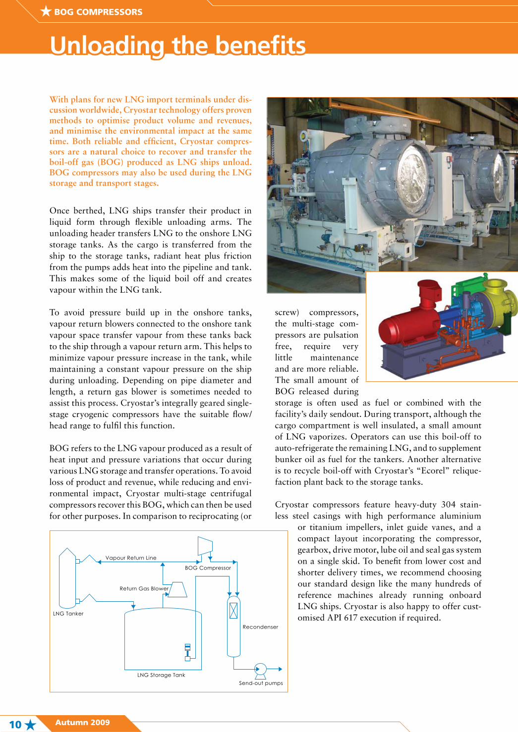
Once berthed, LNG ships transfer their product in liquid form through flexible unloading arms. The unloading header transfers LNG to the onshore LNG storage tanks. As the cargo is transferred from the ship to the storage tanks, radiant heat plus friction from the pumps adds heat into the pipeline and tank. This makes some of the liquid boil off and creates vapour within the LNG tank.
To avoid pressure build up in the onshore tanks, vapour return blowers connected to the onshore tank vapour space transfer vapour from these tanks back to the ship through a vapour return arm. This helps to minimize vapour pressure increase in the tank, while maintaining a constant vapour pressure on the ship during unloading. Depending on pipe diameter and length, a return gas blower is sometimes needed to assist this process. Cryostar’s integrally geared single-stage cryogenic compressors have the suitable flow/head range to fulfil this function.
BOG refers to the LNG vapour produced as a result of heat input and pressure variations that occur during various LNG storage and transfer operations. To avoid loss of product and revenue, while reducing and envi-ronmental impact, Cryostar multi-stage centrifugal compressors recover this BOG, which can then be used for other purposes. In comparison to reciprocating (or
With plans for new LNG import terminals under dis-cussion worldwide, Cryostar technology offers proven methods to optimise product volume and revenues, and minimise the environmental impact at the same time. Both reliable and efficient, Cryostar compres-sors are a natural choice to recover and transfer the boil-off gas (BOG) produced as LNG ships unload. BOG compressors may also be used during the LNG storage and transport stages.
screw) compressors, the multi-stage com-pressors are pulsation free, require very little maintenance and are more reliable. The small amount of BOG released during storage is often used as fuel or combined with the facility’s daily sendout. During transport, although the cargo compartment is well insulated, a small amount of LNG vaporizes. Operators can use this boil-off to auto-refrigerate the remaining LNG, and to supplement bunker oil as fuel for the tankers. Another alternative is to recycle boil-off with Cryostar’s “Ecorel” relique-faction plant back to the storage tanks.
Cryostar compressors feature heavy-duty 304 stain-less steel casings with high performance aluminium
or titanium impellers, inlet guide vanes, and a compact layout incorporating the compressor, gearbox, drive motor, lube oil and seal gas system on a single skid. To benefit from lower cost and shorter delivery times, we recommend choosing our standard design like the many hundreds of reference machines already running onboard LNG ships. Cryostar is also happy to offer cust-omised API 617 execution if required.
BOG COMPRESSORS

Autumn 2009 11
NEWS / TRAINING CENTRE
News
Cryostar Training Centre CatalogueScheduled sessions performed at Cryostar Training Centre, from January to July 2010:
Jan. Feb. March April May June July
Reciprocating pumps - Industrial Gases
week 823-25 Feb
week 247-11 June
Reciprocating pumps - Process Application
week 823-25 Feb
week 247-11 June
Centrifugal pumps - Industrial Gases
week 426-28 Jan
week 184-6 May
Centrifugal pumps - Process Application
week 426-28 Jan
week 184-6 May
TEOB - ECO : Turbo Ex-pander Oil Bearings - ECO
week 1115-19 March
week 285-9 July
TEOB - TP : Turbo Ex-pander Oil Bearings - TP
week 1115-19 March
week 285-9 July
Compressor loaded expan-sion turbine - TC
Turbo expander Magnetic bearing - MTC
week 1719-23 April
Other courses (see course chart on www.cryostar.com)
O N R E Q U E S T
Specific inquiry O N R E Q U E S T
California LNG trucks clean up
This summer saw Cryostar complete the first phase of its Port of Long Beach (POLB) clean energy fuels project in California. Currently the largest station of its kind in the world, POLB fuels up to 300 trucks per day.
POLB together with its neighbour, the Port of Los Angeles, handles 35 percent of ocean imports into the US. POLB has implemented a “Clean Truck Program” which will slowly eliminate older, polluting trucks from the port.
Organized and designed by Cryostar Automa-tion (CSA) with support from Cryostar USA (CSUSA), commissioning for the first phase of the project was carried out during June 2009 and includes the first software developed by Cryostar to control its SubTran LNG sub-merged pumps.
Cryostar reveals breakthrough LNG technologies
October offers an opportunity for LNG customers to witness Cryostar unveiling two new key products, which the company is confident will revolutionise regasification and fuel gas supply.
LNG shipping and distribution technology is advancing rapidly, and Cryostar’s pioneering work in this field yields constant benefits to customers wishing to stay ahead of the game.
“We are very proud to present and demonstrate two new products to the market on the 14th and 15th of October 2009, at our headquarters in Hésingue, France,” says Cryostar’s Director Process and LNG, Bernard Mann.
Customers are invited to groundbreaking demonstrations of EcoVap, Cryostar’s patented pro-pane loop regasification process, and also a new HP fuel gas supply system. EcoVap features a 1MW rated regasification skid with open loop technology, suitable for installation on LNG RVs and FSRUs.
The HP fuel gas supply system is for two-stroke marine diesel DF engines, and leverages Cryo-star’s expertise in supply, installation and control of high-pressure liquid pumping systems.
“These products will change the face of regasification and fuel gas supply as we know it,” says Mann.
Hydrocarbon turbines for Algeria
June saw Cryostar book two major orders worth €7 million for natural gas processing plant turbines for Algerian projects. At El Merk, oil and gas infrastructure supplier Petrofac put in the order with Cryostar, while Italy’s Saipem has bought turbines for project Hassi Messaoud. The orders, for magnetic bearing turbines model MTC500, will be shipped in the later part of 2010