Embed Size (px)
Citation preview

OWNER'SMANUAL
MODEL NO.
536.255870
Caution:Read and followall Safety Rulesand InstructionsBefore Operating
This Equipment
CRRFTSMRN°15.0 HP TWiN CYLIALL=WHEEL43" MOWER DECK6-SPEED TRANSAXLELAWN TRACTOR
R
o Assembly° Operation° Customer Responsibilities° Service and Adjustment
SEARS, ROEBUCK AND CO., HOFFMAN ESTATES, IL 60179

s .0LEa AITHESE INSTRUCTIONS ABE FOR YOUR PROTECTtON_ PLEASE READ THEM CAREFU LLY=
IMPORTANT
THIS CUTTING MACHINE IS CAPABLE OF AMPUTATING HANDS AND FEET AND THROWING OBJECTS=. FAILURE TO OBSERVE THE
FOLLOWING SAFETY INSTRUCTIONS COULD RESULT IN SERIOUS iNJURY OR DEATH°
l. GENERAL OPERATION:
e Know controls and how to stop quickly..o Read, understand, and fotlQy_ atl instructions in the manual and
on the machine before starting.• Only allow responsible adults, who are familiar with
Instructions, to operate the machine.• - 'Wear safety glasses or eye shields when assembling or
operating the machine.Do not operate machine when barefooted. Always wear,_ubstantial footwear, preferably steel*toed shoes.
e. Do not wear loose fitting clothing that could get caught in.moving parts.
• Clear the area of objects such as rocks, toys, wire, etc., whichcould be picked up and thrown by the blade(s).
• Be sure the area is clear of other people before mowing,. Stop' machine if anyone enters the area,
e Never carry passengers.e. Do not mow in reverse unless absolutely necessary., Always
' look down and behind before and while backing.• :. Beaware of the mower discharge direction end do not point it at
.'anyone, Do not operate the mower without either the entiregrass catcher or the guard in place°
e Slow down before turning.o Never leave a running machine unattended. Always turn off
blades, set parking brake, stop engine, and remove keys beforedlsmounting_
e Turn off blade(s) when not mowing.
e Stop engine before removing grass catcher or uncloggingchute.
e Mow only in daylight or good artificial fight..e Do not operate the machine whlte under the influence of alcohot
or drugs.• Watch for traffic when operating near or crossing roadways.• Use care when mowing around a fixed object to prevent the
blade(s) from strtkfng tt_ Never deliberately run over any foreign.obJect,,
e Use extra care when loading or unloading the machine Into atraf!er or truck,
e Use care when putl_ng loads of using heavy equipmentao Useonly approved drawbar hitch points.,b_ LImtt loads to those that you can safely control€,. Do not turn sharply. Use care when backing,d. Use counterweight(s), wheel weight or tire chains when
suggested in attachment(s) instructions,.
IL SLOPE OPERA1]ON:
Slopes are a major factor related to loss-of-control and tip-overaccidents, which can result in severe injury or death All slopes
require extra caution. I! you cannot back up the slope or if you feetuneasy on It, do not mow it.
DO
e Mow up and down slopes, not across.e Remove obstacles such as rocks, tree limbs, etc.
e Watch for holes, ruts, or bumps. Uneven terrain could overturnthe machine. Tall grass can hide obstacles.
• Usa slow speed. Choose a low gear so that you will not have to
stop or shift while on the slope=e Follow the manufacturer*s recommendations for whee_ weights
or counterweights to improve stabt]ity_e Use extra care with grass catchers or other attachments., These
can change the stability of the machfne,_• Keep all movement on the slopes slow and gradual. Do not
make sudden changes in speed or direction.• Avoid starting or stopping on a slope, If tires lose traction, turn
off the blade(s) and proceed slowty straight down the slope.
DO NOT
• Do not turn on stapes unless necessary, and then slowly andgradually downhill, if possible_
• Do not mow near drop-oils, ditches or embankments., The
mower could suddenly turn over if a wheel is over the edge of acliff or ditch, or if an edge caves in_
e Do not mow on wet grass. Reduced traction could causesliding.
• Do not try to stabilize the machine by putting your foot on theground.
• Do not use grass catcher on steep slopes
ill. CHILDREN:
Tragic accidents can occur if the operator Is not alert to the presenceof children, Children are often attracted to the machine and themowing activity Never assume that children will remain where youlast saw them_
a Keep children out of the mowing area and under the watchfulcare of another responsible adult.,
e Be alert and turn machine off if children enter the area.
• Before and when backing, look behind and down for smallchtldreno
• Never carry chtldren_ 3"hey may fall off and be seriously injuredor interfere with safe machine operation.
• Never allow children to operate the machine.• Use extra care when approaching blind corners, shrubs, trees,
or other objects that may obscure vision.
IV., SERVICE:
e Use extra care in handilng gasoline and other fuels. They areflammable and vapors are explosive.m Use only an approved container,b Never remove gas cap or add fuel with the engine running
Altow engine to cool before re*fueling. Do not smokerc. Never ro-fue_ the machine indoors..d_ Never store the machine or fuel container inside where
there is an open flame, such as in a water heater,e Check fuel supply before each use allowing space for
expansion as the heat of the engine andlor sun can causegasoline to expand and ovedtow the tank.,
e Use extra care when handling battery acid. Acid contact wlth
skin may cause severe burns_ Eye contact may causeblindness,
e Use extra care when servtcLng the battery_ Explosive gas isproduced in the battety_ Do not service the battery whilesmoking or near an open spark or flame_ This may cause thebattery to explode causing serious Injury,
e Never run a machine inside a closed area. Exhaust fumes
contain CARBON MONOXIDE, an ODORLESS and DEADLYGAS.
a Keep nuts and bolts, especially blade attachment bolts, tightand keep equipment in good condition=
e Never tamper with safety devices., Check their operationregularly.,
• Do not change the engine governor settings or over speed
engine.e Reduce fire hazards. Keep machine free of grass, leaves, or
other debris build-up Clean up otl or fuel spillage° Allowmachine to cool before storing,
• Stop and inspect the equipment if you strike an object., Repair, ifnecessary, before restartfng.
• Never make adjustments or repairs with the engine running°e Grass catcher components are subject to wear, damage, and
deterioration, which could expose moving parts or allow
objects to be thrown.. Frequently check components andreplace with manufacturer's recommended parts, when
necessary_• Mower blade(s) are sharp and can cuL Wrap the blade(s) or
wear gioves, and use extra caution when servicing them..e Check brake operation frequently_ Adjust and service as
required,.
I A LOOK FOR THIS SYMBOL TO POINT OUT IMPORTANT SAFETY PRECAUTIONS,, IT MEANS--ATTENTION!!!BECOME ALERT!!! YOUR SAFETY IS INVOLVED.
2
CONGRATULATIONSon yourpurchaseof a SearsCraftsmanTractor.It hasbeendesigned,engineeredandmanufacturedtogiveyouthebestpossibledepend-abilityandperformance.Shouldyouexperienceanyproblemyoucannoteasilyremedy,pleasecontactyournearestSearsServiceCenterlDepartment.Wehavecompetent,well-trainedtechniciansandthepropertoolstoserviceorrepairthisunit,,Pleasereadandretainthismanual.Theinstructionswillenableyou to assembleand maintainyourtractorproperlyAlwaysobservethe"SAFETYRULES.,"
MODELNUMBER536255870SERIALNUMBERDATEOFPURCHASETHEMODELANDSERIALNUMBERSWILLBEFOUNDONAPLATEUNDERTHESEAT_YOUSHOULDRECORDBOTHSERIALNUMBERANDDATEOFPURCHASEANDKEEPINASAFEPLACEFORFUTUREREFERENCE.
MAINTENANCE AGREEMENTA Sears Maintenance Agreement is available on thisproduct.. Contact your nearest Sears Store for details.
CUSTOMER RESPONSIBILITIES• Read and observe safety rules,e Follow a regular schedule in maintaining, caring for and
using your unit.,o Follow the instructions under "Customer Responsi-
bilities" and "Storage" sections of this manual,
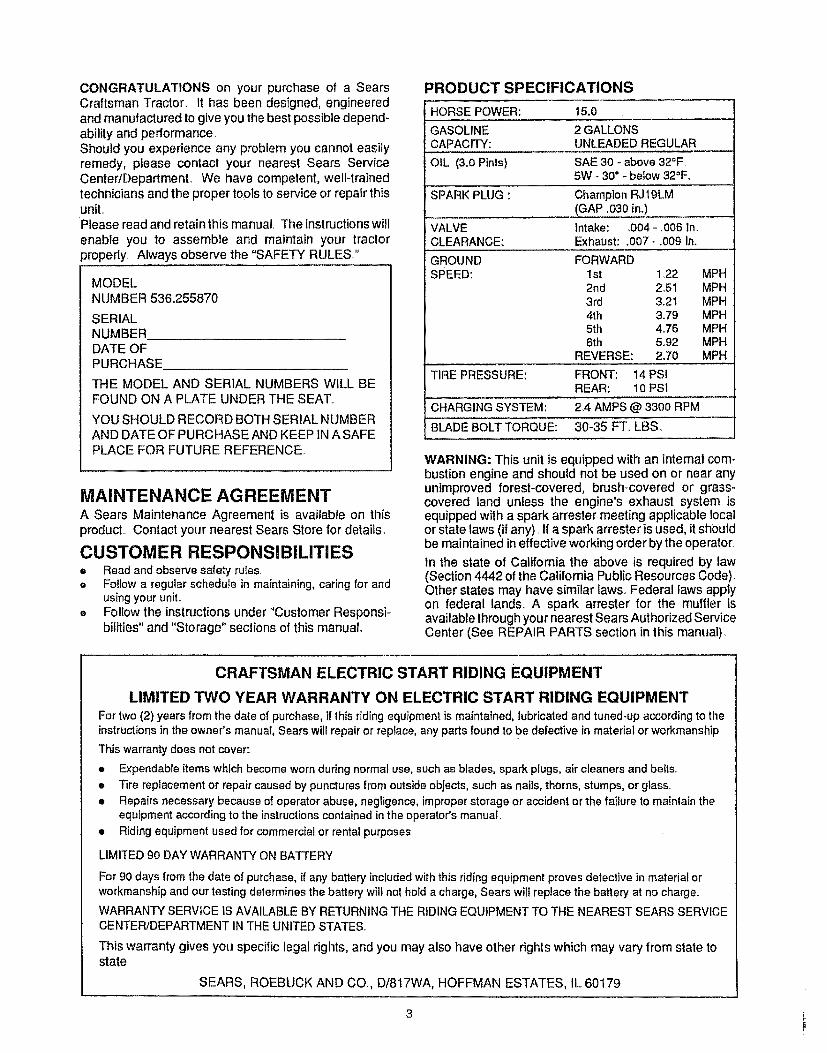
PRODUCT SPECIFICATIONS
HORSE POWER:
GASOLINECAPACITY:
OIL (3,,0 Pints)
SPARK PLUG :
VALVECLEARANCE:
GROUNDSCEED:
TIRE PRESSURE:
CHARGING SYSTEM:
BLADE BOLT TORQUE:
15.0
2 GALLONSUNLEADED REGULAR
SAE 30 - above 32°F,5W - 30" - below 32°F_
Champion RJ 19LM(GAP ,030 in.)
Intake: ,004 -,006 in,Exhaust: ,007- ,009 in,
FORWARD1st 1222nd 2513rd 3,214th 3°795th 4.,766th 592
REVERSE: 2,70
FRONT: 14 PSfREAR: 10 PSI
2,4 AMPS @ 3300 RPM
30-35 FT, LBS,,
MPHMPHMPHMPHMPHMPHMPH
WARNING: This unit is equipped with an internal com-bustion engine and should not be used on or near anyunimproved forest-covered, brush-covered or grass-covered land unless the engine's exhaust system isequippedwith a spark arrester meeting applicable localor state laws (if any)._If a spark arrester is used, it shouldbe maintained in effectiveworking order bythe operator.
In the state of California the above is required by law(Section 4442 ofthe California PublicResources Code),Other states may have similartaws,,Federal laws applyon federal lands,, A spark arrester for the muffler isavailable throughyour nearestSears Authorized ServiceCenter (See REPAIR PARTS section in this manual).
CRAFTSMAN ELECTRIC START RIDING EQUIPMENT
LIMITED TWO YEAR WARRANTY ON ELECTRIC START RIDING EQUIPMENT
For two (2) years from the date of purchase, if this riding equipment is maintained, lubricated and tuned-up according to theinstructions in the owner's manual, Sears will repair or replace, any parts found to be defective in material or workmanship
This warranty does not cover:
• Expendable items which become worn during normal use, such as blades, spark plugs, air cleaners and belts..
• Tire replacement or repair caused by punctures from outside objects, such as nails, thorns, stumps, or glass.
= Repairs necessary because of operator abuse, negligence, improper storage or accident or the failure to maintain theequipment according to the instructionscontained in the operator's manual.
• Ridingequipment used for commercial or rental purposes..
LIMITED 90 DAY WARRANTY ON BATTERY
For 90 days from the date of purchase, if any battery included with this riding equipment proves defective in material orworkmanship and our testing determines the battery' wilt not hold a charge, Sears will replace the battery at no charge,.
WARRANTY SERVICE IS AVAILABLE BY RETURNING THE RIDING EQUIPMENT TO THE NEAREST SEARS SERVICECENTERIDEPARTMENT IN THE UNITED STATES
This warranty gives you specific legal rights, and you may also have other rights which may vary from state tostate.
SEARS, ROEBUCK AND CO., D/817WA, HOFFMAN ESTATES, IL 60179
3

TABLE OF CONTENTSSAFETY RULES ................................................... 2PRODUCT SPECIFICATIONS ........................... 3CUSTOMER RESPONSIBILITIES .....3, 17-22WARRANTY ........................................................... 3TABLE OF CONTENTS ..........................................4INDEX ......................................................................... 4TRACTOR ACCESSORIES ............................... 5CONTENTS OF HARDWARE PACK ............... 6ASSEMBLY ............................................... 7-! !
OPERATION .................................................. 12-16SERVICE AND ADJUSTMENTS ..............23-33TROUBLE SHOOTING .......................... 34-35STORAGE ........................................................................36REPAIR PARTS ...................................... 38-63ENGINE REPAIR PARTS ......................... 64-71TRANSAXLE REPAIR PARTS ................. 72-73PARTS ORDERING/SE RVlCE ...... Back Cover
INDEX
AAccessories ............................................5Adjustments:
Blade Brake .............................................26Brake ...........................................................29Carburetor ..........................................33Mower Deck Leveling:Fmnt:l'o-Rear .........................................25Side-To-Side ........................................24Mower Deck Height .................................25Seat ......................................................28Throttle Control Cable ...................33
Air Screen, Engine ................................21Assembly ....................................................7-1 t
BBattery:
Charging ...................................................9Cleaning ....................................................20Installation .........................................10-11Battery Acid Levels ..........................9, 20Preparation ........................................................8Starting with Weak Battery ....................31Storage .................................................................36Term inals ..................................._.........20
Belt:Tractor DriveRemoval/Replacement .....................27Mower Blade DriveRemovaltReplacement ........................27
Blade:Sharpening .............................................20Replacement .............................................19
Brake Adjustment ........................................29C
Carburetor Adjustment ...............................33Controls, Tractor..........................................12Customer Responsibilities..............3, 17-22
Air Screen, Engine ..............................21Battery :........................................................20Blade ...................................................19-20Brake Operation .....................................19Cooling Fins, Engine ...................................21Engine Oil ...................................................3, 2IFuel Filter .....................................................22Lubrication Chart .....................................18Schedule ...........................................................17Spark Plugs ................................................22Tire Care ...........................................9, 19, 30
Cutting Height, Mower ..........................14E
Electrical:interlocks and Relays ..............................3t
Engine:Air Filter .............................................22Air Screen ..........................................21Cooling Fins ..........................................21Oil Change ....................................... 21Oil Level ......................................15, 21Oil Type ................................ 3, 21Preparation .............................................15Starting ....................................................t5Storage ............................................. 36
FFilter:
Fuel .......................................... 22Fuel:
Type ........................................... 3, 15Storage ..............................................36
HHeadlights .....................................................31Hood Removai!lnstal]altion .............. 32
LLeveling, Mower Deck ....................24-25Lubrication:
Chart ..........................................................18M
Mower:Adjustment, Front-To-Rear .............25Adjustment, Side-To-Side ................24Adjustment, Deck Height .................25Blade Sharpening ............................20Blade Replacement ......................................19Brake Adjustment ...............................29Cutting Height ........................................14installation ..............................................23-24Operation ......................................................14Removal ..........................................................23
Mowing Tips .........................................16Mulching Mowing Tips .............................16Muffler _....................................................22Spark Arrester ..........................................3, 22Mulching Plug:
Removal ..................................................20O
Oil:Cotd Weather Conditions ........ 15, 21Engine ...............................................................21Storage .................................................36Type ...........................................................3, 15, 21
Operation ....................................................12-16Operating Your Mower ..........................14Options:
Accessories ................................................5Spark Arrester ................................3, 22
PParking Brake ............................... 13-14Parts Bag ............................................... 6Product Specifications ............................3
RRepair Parts:
Engine ............................... 64-71Tractor ................................ 38-63Transaxle .............................. 72-73
SSafety Rules .................................................2Service and Adjustments .............23-33
Blade Brake ..........................................26Brake Rod ................................ 29-30Carburetor ..........................................33Choke Control ................................. 32Control Lever .............................................30Fuse ..........................................................31Hood Removal/Installation ..................32Tractor Drive Belt:Removal/Replacement .............27-28Mower Blade Drive Belt:Removal/Replacement .................. 27Mower Deck Adjustment:Front-To-Rear .......................................25Side-To-Side ........................................24Mower Deck Height ..........................25Mower Deck Removal .......................23Mower Deck Installation ........... 23-24Seat ......................................................28Steering Gear .........................................29Tire Care .......................................9, ! 9, 30Throttle Control ....................................33Wheel Repair ....................................30
Spark Plugs .............................................22Specifications ..............................................3Starting the Engine .......................... 15Steering Wheel .........................................7Stopping the Tractor .......................... 13Storage ..............................................................36
TTable of Contents .........................................4Throttle Control Cable
Adjustment ..................................................33Tires .................................................9, t9, 30Tire Pressure ...............................3, 9, 19Transaxle:
Cooling ..................................................20Troubleshooting Points .................34-35
WWarranty ...........................................................3

A CCESSORIES AND ATTACHMENTS
These accessories and attachments were available when the unit was purchased They are also available at most Sears retaiJoutlets, catalog and service centers, Most Sears stores can order these items for you when you provide the model number of yourtractor.
ENGINE CUSTOMERMAINTENANCE
SPARK PLUG MUFFLER AiR FILTER BELTSGAS CAN ENGINE OIL STABILIZER BLADES
PERFORMANCESears offers a wide variety of attachments that fit your vehicle_ Many of these are listed below with brief explanations of how theycan help you.. This list was current at the time of publication;however, it may change in future years - more attachments may beadded, changes may be made in these attachments, or some may no longer be available or lit your model Contact your nearestSears store for the accessories and attachments that are available for your unit.
Most of these attachments do not require additional hitches or conversion kits (those that do are indicated) and are designed foreasy attaching and deattaching
GRASS CATCHER .. lets you collect grass c_ippings andleaves for a healthier, neater looking lawn.
LAWN SWEEPERS - lets you collect grass clippings andleaves.
CARTS - make hauling easy.. Variety of sizes available
ROLLER - for smoother lawn surface, 36-inch wide, 18 inchdiameter water tight drum holds up to 390 lbs of weight..Rounded edges prevent harm to tuff. Adjustable scraper au-tomatically cleans drum.
SPREADERSiSEEDERS - make seeding, fertilizing andweed killing easy. Broadcast spreaders are also useful forgranular deicers and sand.
CORING AERATOR - takes small plugs out of soil to allowmoisture and nutrients to reach grass roots. 36-inch swath24 hardened steal coring tips. 150 Ibs. capacity weight tray
AERATOR - promotes deep root growth for a healthy lawn_Tapered 25" steal spikes mounted on 10-inch diameter discspuncture holes insoif at close intervals to let moisture soak in..Steal weight tray for increased penetration..
MULCH RAKE!DE]HATCHER - loosens soil and flips thatchand matted leaves to lawn surface to easy pick up, Twentyspring tine teeth.. Useful to prepare bare areas for seeding°Available for rear mounting.
SPRAYERS - use 12-volt DC electric motor that connects tothe tractor battery or other 12-volt source Includes booms forautomatic spraying when pullingand hand held wand for spotspraying Wand has adjustable spray pattern. For applyingherbicides, insecticides,fungicides, and liquid fertilizers.
48" SNOW BLADE - has a rugged, heavy gauge steel blade.Spring loaded blade glides over uneven surfaces. Can be ad-justed from seat for straight position, or 35 degrees left orright..Locks in raised position for traveling. Wheel weights andtire chains are recommended.
TWO-STAGE SNOW THROWER - has a 42-inch swath and a
second stage impetler capable of moving more than 70 tonsof snow per hour and throwing it accurately in any directionyou choose Driver controlled discharge chute turns a 160 de-gree arc Wheel weights and tire chains are recommended,.
TIRE CHAINS - are heavy duty: closely spaced extra-largecross tinks give smooth ride, outstanding traction
WHEEL WEIGHTS - for rear wheels provide needed tractionfor snow removal or dozing heavy materials. In pairs (80 Ibseach).
TRACTOR COVER protects tractor from weather Made ofEvolution 3 fabric (water-repellent, extremely breathable, lightweight, soft, non-abrasive, pliable in all temperatures,durable, stain/tear/puncture resistant, wil! not shrink orstretch.. (CATALOG ONLY)
TILLER has 5 hp engine and 36" swath to prepare seed beds,cultivate and compost garden residue. Tiller has its own built-in lift and depth control system and does NOT require asleeve hitch. Fits any lawn, yard, or garden tractor. Simplyhook up to the tractor drawbar and go!

................... .............CONTENTS OF HARDWARE PACK
Parts packed separately in carton
i
_h:._,t I
i
Steering Wheel Parts Bag Battery Acid
Owner's Manual
Parts Bag contents shown actual size unless noted
Steering Wheel Assembly Parts
\
1 - Spacer
© [ ]1 - Spring Pin
1 - Spare Key

ASSEMBL Y
TOOLS REQUIRED FOR ASSEMBLYA socket wrench wilt make assembly easier. Standard wrenchsizes are listed
3/8 inch wrench(1)
(1)
(I)
(1)
(1)
Pliers
Utility knife
Screwdriver (Small Phillips with a 1/4 inch shank)
Hammer
(1) Tire pressure gauge
(2) 7t16 inch wrenches
(1) 9!16 inch wrench
(1) Tape measure
When right and left hand is mentioned in this manual, itmeans when you are in the operating position (seated behindthe steering wheel).
TO REMOVE TRACTOR FROMCARTON
UNPACK CARTON
• Open top flaps,, Remove cardboard from top of woodcrate,
IMPORTANT: FOR SHIPPING PURPOSES THE MOWERDECK WAS NOT ASSEMBLED ON TRACTOR. THEMOWER DECK IS ATTACHED TO TOP FRAME AND SIDEPANEL OF CARTON WHEN REMOVING MOWER DECKFROM CARTON, MAKE SURE IT DOES NOT TOUCHTRACTOR,
e
o
e
o
o
o
o
o
o
Using a 3/8" wrench, remove bolt that secures mowerdeck hitch to top frame in top of carton
Remove top frame from carton
Carefully remove contents of parts box (see CONTENTSOF HARDWARE PACK on page 6).
Cut down corners of side panel across from mower deckwith a utility knife and lay side panel down
Hold side panel (with mower deck attached) upright andcut down corners,
Carefully lower side panel with mower deck,,
Lay down end panels of carton and discard cardboard fromalongside tractor.
Remove bolt that secures mower deck to side panet ofcarton with 3/8" wrench.
Remove mower deck from carton, Lay aside forinstallation later, Remove cardboard from dischargechute,
• Remove plastic wrap from seat and hood
TO INSTALL STEERING WHEEL
(See Fig, 1)
• Position front wheels straight forward.
e Place spacer on steering shaft,,
• Place steering wheel on steeringsteering wheel down firmty
shaft, Push
STEERING
WHEEL
SPRING PIN
CLUTCHLEVER
FIG. 1
SHIFT CONTROLLEVER BRAKE, CLUTCH PEDAL
VIEW FROM RIGHT SIDE OF TRACTOR
FIG. 2
e Align cross holes in steering wheel with holes insteering shaft. NOTE: Use a small Phillips screw-driver with a 1f4 inch shaft to align the holes, Keepscrewdriver in place as you drive the spring pin in,
• From the left side, drive spring pin (found in parts bag)through opposite side with a hammer,,
BEFORE ROLLING TRACTOR OFF SKID
(See Fig. 2)IMPORTANT: CHECK FOR AND REMOVE STAPLES INSKID THAT MAY PUNCTURE TIRES OF TRACTOR BEFOREATTEMPTING TO ROLL OFF SKID.,
• Carefully cut wire ties (front and back) holding tractor toskid..
• Release parking brake by depressing brake-clulchpedal,,
• Place shift control lever in NEUTRAL position.
• Carefully roll tractor backwards off wood skid,(ASSISTANCE MAY BE REQUIRED,,)
IMPORTANT: DO NOT LIFT TRACTOR BY HOOD ORFENDER,
7!
ASSEMBLY
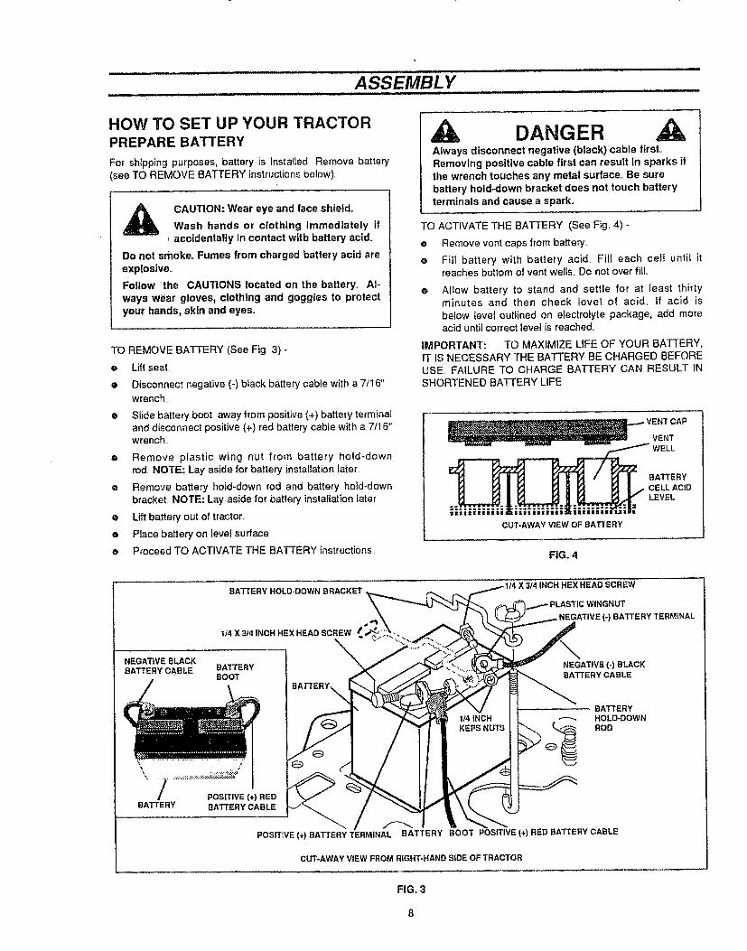
HOW TO SET UP YOUR TRACTORPREPARE BATTERY
For shipping purposes, battery is installed, Remove battery(see TO REMOVE BATTERY instructions below),
CAUTION: Wear eye and face shietd_
Wash hands or clothing immediately if_-accidentally in contact with battery acid_
Do not smoke° Fumes from charged battery acid areexplosive°
Follow the CAUTIONS located on the battery° Al-
ways wear gloves, clothing and goggles to protectyour hands, skin and eyes.
TO REMOVE BATTERY (See Fig 3) -
e Lift seal
• Disconnect negative (-) black battery cable with a 7It6"wrench
e Slide battery boot away from positive (+) battery terminaland disconnect positive (+) red battery cable with a 7t16"wrench..
e Remove plastic wing nut from battery hold-downrod NOTE: Lay aside for battery installation later
• Remove battery hold-down rod and battery hold-downbracket. NOTE: Lay aside for battery installation later
• Lift battery out of tractor,.
e Place battery on level sufface=
e Proceed TO ACTIVATE THE BATTERY instructions
DANGERAlways disconnect negative (black) cable first.Removing posltlve cable first can result In sparks ifthe wrench touches any metal surface° Be surebattery hold-down bracket does not touch batteryterminals and cause a spark.
TO ACTIVATE THE BATTERY (See Fig, 4) -
e Remove vent caps from battery,.
e Fill battery with battery acid, Fill each cell until itreaches bottom of vent wells_ Do not over fill,.
O Allow battery to stand and settle for at least thirtyminutes and then check level of acid, if acid isbelow level outlined on electrolyte package, add moreacid until correct level is reached,,
IMPORTANT: TO MAXIMIZE LIFE OF YOUR BATTERY,1T IS NECESSARY THE BATTERY BE CHARGED BEFOREUSE, FAILURE TO CHARGE BATTERY CAN RESULT INSHORTENED BATTERY LIFE
VENT CAP
VENT
|1155:
CUT'AWAY ViEW OF BATTERY
BATTERY
CELL ACIDLEVEL
,=
FIG. 4
BATTERY HOLD-DOWN BRACKET ,
NEGATIVE BLACK
BATTERY CABLE
BATTERY
1/4 X3/4 INCH HEX HEAD SCREW
\BAT_'ERYBOOT
POSITIVE (+) REDBATTERY CABLE
POSITIVE (+) BATTERY TERMINAL
X 3/4 INCH HEX HEAD SCREW
. NEGA3'IVE (-) BATTERY TERMINAL
NEGATIVE (-) BLACKBATTERY CABLE
BATTERYHOLD*DOWN
_ ROD
BOOT POSITIVE (+) RED BATTERY CABLE
CLrr-AWAY VIEW FROM RIGHT-HAND SIDE OF TRACTOR
FIG. 3

ASSEMBL Y
CAUTION: Handle electrolyte with care°It is an acid and poison. Always wear eyeshields, and protect skin when handlingacid or battery.
POISON - CAUSES SEVERE BURNS
Contains sulfuric acid,,
Avoid contact with skin, eyes or clothing°To prevent accidents, neutralize excess acid withbaking soda and rinse empty container with water°
TREATMENT:
EXTERNAL - Flush with water.
INTERNAL - Drink large quantities of water or milk,.Follow with milk of magnesia, beaten eggs orvegetable oil Call physician immediately°
EYES - Flush with water for 15 minutes and getprompt medical attention.
KEEP OUT OF THE REACH OF CHILDREN
e Charge battery at a rate of six (6) amps for t hour.Use a 12-volt battery charger. Observe all safetyprecautions required for battery charging Complete as-sembly section of this manual while waiting for battery tocharge°
e Check acid level after the battery is charged_ Ifacid has fallen below correct level, add distilled or ironfree water
e Install vent caps to cover vent wells,. Wash top of batterywith water to remove any acid, then wipe dr#,,
e Check battery case for leakage to make sure that nodamage has occurred in handling,
e Dispose of excess battery acid. Neutralize acid for dis-posal by adding it to four inches of water in a five (5) gal-lon plastic container Stir with a wooden or plastic paddlewhile adding baking soda until the addition of more sodacauses no more foaming.
CHECK "TIRE PRESSURE
For shipping purposes, the tires on your tractor were over-in-flated at the factory° Correct tire pressure is important ior bestcutting performance..
• Remove hub caps by placing two fingers in hole in eachcap and pulling them from the wheels..
e Use tire pressure gauge to check amount of air in tires.
• Reduce tire pressure to PSI shown in "PRODUCTSPECIFICATIONS" on page 3 of this manual
e Replace hub caps. Position on wheels and push firmly
TO INSTALL MOWER DECK
e Place cutting height adjustment in highest position bypressing cutting height adjustment pedal all the waydown until it latches. See TO SELECT MOWERCUTTING HEIGHT in OPERATION section of thismanual 1f cutting height is not in highest position, thedeck brackets will hit the lift arms while sliding the deckunder the tractor,.
e Place mower deck on right side of tractor with chutedeflector away from tractor
MOWER DECKENGAGEMENT CABLE
OPEN SIDE OF _ MOWER DECKSPRING END \ BELT GUARD
MOWER CLUTCHCABLE SPRING
IDLER PULLE
MOWER DECKDRIVE BELT
DECKHITCH
O
o
FIG. 5
Turn front wheels of tractor to maximum left turn_.
Lift deck hitch and slide deck under tractor to a centered
position_
e From left side of tractor, slide deck rearward Thenconnect mower deck engagement cable to mower clutchcable spring (see Fig..5).Be sure open side of spring endis pointed down (see Fig_ 5 inset),
• Verify that mower belt is routed as shown in Fig 5, andfree of the deck hitch.
• Slide deck toward front of tractor Pull lower engine pulleybelt guides away from engine and slip mowerdeck drive belt onto lower engine pulley.. Reposition beltguides to 1/16" from pulley if needed
LOWER ENGINEPULLEY BELT GUIDES
LOWERENGINE PULLEY
FIG. 6

ASSEMBLY .......................................
• Underneath the footrests of the tractor, remove hairpincotters and flat washers from the left and right hand
hanger pins and lay aside (see Fig. 7A)
• Remove hitch rod and hairpin cotter from front mounting
bracket and lay aside (see Fig 7B)
® Align holes in the mower deck hitch with the top set ofholes in the front mounting bracket and reinstall the hitch
rod and hairpin cotter (see Fig 7B),
e Place cutting height adjustment pedal in lowest position
by moving memory rod to position ! and pressing pedaflatch to retease cutting height adjustment pedal NOTE:Be sure left and right rear lift arms are to the inside of the
left and right deck lift brackets (see Fig,, 7A).
e Lift deck slightly and flex left rear hanger pin inward to
snap hanger pin into left deck lift bracket stot Securehanger pin in place with flatwasher and hairpin cotter re-moved earlier,
e Lift deck slightly and flex right rear hanger pin inward to
snap hanger pin into right deck lift bracket slot. Securehanger pin in place with flatwasher and hairpin cotterremoved earlier (see Fig. 7A)
e Check mower deck leveling and adjustment as required
(See TO LEVEL MOWER DECK in SERVICE ANDADJUSTMENTS section of this manual).
CHECK FOR PROPER POSITION OF ALLBELTS
• .See figures shown for replacing motion and mower bladedrive belts in SERVICE AND ADJUSTMENTSsection of this manual Verify belts are routed correctly
TO ADJUST MOWER DECK WHEELS
(See Fig. 8)
Mower deck wheels may be adjusted to one of four positionsAlways adjust both wheels to same position. NOTE: Do Notadjust wheels to support mower deck while mowing oruneven cutting will result
• Park tractor on a firm, level surface, such as a driveway
or garage floor._
e Set cutting height adjustment to lowest anticipatedcutting heighL Deck wheels should be 1/4" off ground, ifnot, adjust as follows:
• Remove axle bolt and nut holding each wheel towheel mounting bracket with two 9It6" wrenches
e Change wheel height adjustment by relocating eachwhee! into desired hole of wheel mounting bracket.
e Reinsta!l bolt and nut on each side and secure nutstightly.
CHECK BRAKE SYSTEM
• After you learn how to operate your tractor, check opera-tion of tractor brake (see BRAKE OPERATION inCUSTOMER RESPONSIBILITIES section of this
manual)
DECK LIFTBRACKET
FLATWASHER
HAIRPIN \_
COTTE R
HANGER PIN
REAR LIFT ARM(RIGHT SIDE)
FRONTMOUNTINGBRACKET
VIEW FROM RIGHT SIDE OF TRACTOR
FIG,,7A
HAIRPINCOTTER
H_TCHRODMOWER DECKHITCH
VIEW FROM FROI_FrOF TRACTOR
FIG. 7B
MOWER DECK
WHEEL
NUT
AXLE BOLT
\
WHEELMOUNTINGBRACKET
RIGHT SIDEWHEELBHOWN
FIG, 8
REINSTALL CHARGED BATTERY
(See Fig. 9)
• Raise seat and place battery back in tractorwith positive (+) terminal toward right side of tractor..NOTE: Be sure ignition key is in OFF position.
• Place battery hold-down bracket through slot in back ofconsole. NOTE: Turn bracket to side, pface throughslot
inconsole and rotate upright
10
ASSEMBLY
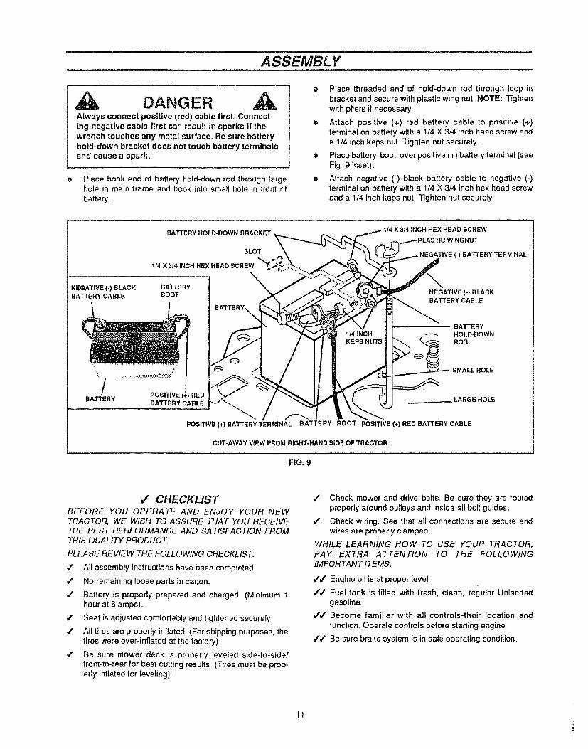
DANGERAlways connect pos[ttve (red) cable first. Connect-ing negative cable first can result in sparks if thewrench touches any metal surface. Be sure batteryhold-down bracket does not touch battery terminalsand cause a spark.
Place hook end of battery hold-down rod through largehole in main frame and hook into smalt hole in front of
batter_'..
Place threaded end of hold-down rod through loop in
bracket and secure with plastic wing nut, NOTE: Tighten
with pliers if necessary
e Attach positive (+) red battery cable to positive (+}terminal on battery with a 1/4 X 3/4 inch head screw and
a 1/4 inch keps nut, Tighten nut securely.
o Place battery boot over positive (+) battery terminal (seeFig 9 inset),
e Attach negative (+) black battery cable to negative (-)
terminal on battery with a 1/4 X 314 inch hex head screwand a 1t4 inch keps nut, Tighten nut securely,
BATTERY HOLD-DOWN BRACKET
SLOT
114 X 3/4 INCH HEX HEAD
NEGATIVE (-) B LACK BATTERYBATTERY CABLE BOOT
t
/ .oo+,+POSITIVE (+) BATTERY TERMINAL
X 3/4 INCH HEX HEAD SCREW
(-) BATTERY TERMINAL
NEGATIVE (-) BLACKBATTERY CABLE
BATTERYHOLD-DOWN
ROD
SMALL HOLE
ERY BOOT POSITIVE (+) RED BATTERY CABLE
CUT+AWAY VIEW FROM RIGHT-HAND SIDE OF TRACTOR
FIG. 9
,# CHECKLISTBEFORE YOU OPERATE AND ENJOY YOUR NEWTRACTOR, WE WISH TO ASSURE THAT YOU RECEIVETHE BEST PERFORMANCE AND SATISFACTION FROMTHIS QUALITY PRODUCT,
PLEASE REVIEW THE FOLLOWING CHECKLIST:
All assembly instructions have been completed,
/ No remaining loose parts in carton,
./ Battery is properly prepared and charged, (Minimum Ihour at 6 amps)+
/ Seat is adjusted comfortably and tightened securely
/ All tires are properly inflated, (For shipping purposes, thetires were over-inflated at the factory),
/ Be sure mower deck is property leveled side-to-side/front-to-rear for best cutting results, (T_res must be prop-erty inflatedfor leveling).
/ Check mower and drive belts. Be sure they are routedproperly around pulleys and inside all belt guides,
,,z Check wiring+ See that all connections are secure andwires are properly clamped.
WHILE LEARNING HOW TO USE YOUR TRACTOR,PAY EXTRA ATTENTION TO THE FOLLOWINGIMPORTANT ITEMS:
,Y/ Engine oil is at proper level,
,1"/ Fuel tank is filled with fresh, clean, regurar Unleadedgasoline,,
,[/ Become familiar with all controls-their tocation andfunction+ Operate controls before starting engine,,
// Be sure brake system is in safe operating condition.
11

OPERATION
KNOW YOUR TRACTORREAD THIS OWNER'S MANUAL, AND SAFETY RULES BEFORE OPERATING YOURTRACTOR
Compare illustrations(see Fig,_I0) withyour tractorto familiarize yourself with locations of various controis and adjustmentsSave this manuat for future reference,
CHECKSTARTINGSEQUENCEINDICATOR
THROTTLE ATTACHMENTCONTROL LEVERLEVER
\
CHOKECONTROL
cUTTING HEIGHTADJUSTMENT PEDAL
_ETER
BRAKE_LUTCH
LATCH
MEMORYROD\
HEADLIGHT SWITCH
_,_ ,. • , ,._,',,....................
FIG, 10
SH|FTCONTROLLEVER
SEARS LAWN TRACTORS conform to the safety standards of THE AMERICAN NATIONAL STANDARDS INSTITUTE
ignition Switch - Used to start and stop engine,.
Choke Control - Used to start a cold engine
Throttle Control Lever - Controls speed of engine
Headlight Switch - Turns headlights on or off_
Ammeter - Shows battery is being charged when engine isrunning_
Check Starting Sequence Indicator - Indicator lights ifwrong starting procedure was used,,
Brake-Clutch Pedal - Used to clutch and braketractor and start engine_
Shift Control Lever -Used to select ground speed rangesand direction of motion (forward-neutral-reverse)_
Parking Brake Latch - Used to lock brake-clutch pedaI downin park position..
Cutting Height Adjustment Pedal - Used to change heightof cuL
Memory Rod. Used with Cutting Height Adjustment Pedal toselect cutting height
Attachment Clutch Lever - Used to engage or disengagepower to mower deck blades.
12

OPERATION
The operation of any tractor can resuftin foreign objects being thrown into the eyes, which can result insevere eye damage Always wear safety gfasses or eye shields while operating your tractor or performingany adjustments or repairs.,
We recommend standard safety glasses, available at SEARS Refail or Catalog Stores, or a wide visionsafety mask for over your glasses
LOW
T HEmG_
G 1., FULLY DEPRESS CDT HEIGHTPEDAL
_J_ _ 2, POSmON MEMORYRODTODESIRED HEtGHT
i_1 3 RELEASECUT HE{GHTPEDAL
1'O_I_.M_SPORY1,, FULLY DEPRESS CUT HE]GHT
PEDAL
• READOPERATORSIMNUAL(S)KNOWLDCATZoN&FUNCTIONOFALLCONTROLS
, KEE_GUARDS SAFETfSHIELDSANDSWffCHESNPLACE J_J'_OWORK NG PROPERLY
* REMOVE OSJECTSTHATCAN BETHROWN BYsueDE(s)
, DO N_ UOW WHEN C_LDREN OR OTHERS ARE" AROUND
• NEVER CARRY CHILDREN OR PASSENGERS
LOOK DOWNAND BERIND BEFORE ANDWHILEBACKINGDONOTMOWWHEREMOWERCANTIPORSLIPIF MACHINESTOPS GOING UP HiLL OISENGAGEBLADE(5_AND SACK DOWN SLOWLY
, REUOYEKEYWHENLEAVINGMACHINEAVOID SUDDEN TURRS
, GO UP AND DOWNSLOPERpNOT ACROSS
PEDAL
ALWAYS SET PARKING BRAKEBEFORE LEAVING OR ENGINE WILLSTOP
1, FULLY DEPRESS BRAKFJCLUTCHPEDAL
2. PUSH LEVER FOWARD AND HOLD
3, RELEASE BRAKEtCLb'TCH PEDAL
TO RELEASE PA._RING BD-,,ttJKEt, FULLY DEPRESS BRAKE.tCLUTCH
PEDAL LEVER W1LL RELEASE
OPERATING IHSTItUCTIOH$....... (READOWNERSMANUAL) _,_._=_!_:_ :._*-..................... _i_
TO START TO STOP TO SHIFT _r, ARS1. DISENGAGEAT[ACHMF___,ffCLUTCH 1, FULLY DEPRESS SRAKEgCLUTCH PEDAL t FULLY DEPRESS BRAKE/CLUTCH PEDAL2. FULLY DEPRESS BRAKEJCLUTCHPEDAL 2, DBENGAGEArTACHMENTCLUTCH 2 SHIFTTODES_REDGEAR3_ SHF[ TO NEUTRAL 3. SH]F[TO NEUTRAL 3. RELEASE BRAKFJCLUTCH PEDAL SLOWLY4. SETTHROTTLETO FULL(CHOKE ]F NEEDED) 4., ENGAGE PARKING BRAKE
\,,,5. TURN IGNiTiON TO START 5 TURN IGNmON TO OFF
HOW TO USE YOUR TRACTORTO SET PARKING BRAKE
e Depress brake-clutch pedal fully (all thG way down) andhold,,
e Never use choke to stop engine,
NOTE: Under certain conditions when unit is standingidle with engine running, hot engine gases may cause "brown-ing" of grass,, To eliminate this possibility, always stop enginewhen stopping tractor on grass areas.
e Push parking brake lever forward and engage notch inparking brake lever against main frame.
o To release parking brake, apply pressure to brake-clutchpedal and spring will automaticaUy release parking brakelever°
STOPPING
MOWER BLADES -
• Puff the clutch lever rearward to the DISENGAGED
position,
CAUTION: Blades will not stop imme-diately. Keep hands and feet from undermower deck and away from dischargechute.
TRACTOR -
• Depress brake-clutch pedal fully (all the way down),
e Place shift control lever in NEUTRAL position.
• Set parking brake before leaving tractor,
ENGINE -
• Move throttle control to SLOW position,
• Turn ignition key to OFF position and remove key, Alwaysremove key when teaving vehicle to prevent unauthorizeduse_
TO USE CHOKE CONTROL
Use choke control whenever you are starting a cold engineDo not use to start a warm engine,
• To engage choke control, pull knob out, Slowly push knobin as engine warms up to disengage,,
TO USE THROTTLE CONTROL
• FAST throttle position is necessary for best bagging andmowing parformance.
• Operating engine at other than FAST position reducesbattery charging rate and the engine cooling air flow,
TO MOVE BACKWARD AND FORWARD
The direction of motion (forward - reverse) and groundspeed ranges (1-2-3-4-5-6) are controlled by shiftcontrollever,,
• Start tractor with brake-dutch pedal depressed and shiftcontrol lever in NEUTRAL position.
• Move shift control lever to reverse or forward speed range_NOTE: Always come to a full stop before changing directionof motion,,
e Slowly release brake-clutch pedal to start movement.
13
t
.................. OPERATZON
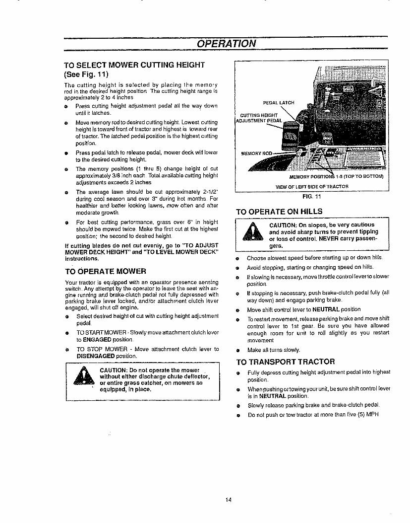
TO SELECT MOWER CUTTING HEIGHT
(See Fig. 11)
The cutting height is selected by placing the memoryrod in the desired height position The cutting height range isapproximately 2 to 4 inches
o Press cutting height adjustment pedal all the way+ downuntil it lalches,+
• Move memory rod to desired cutting height. Lowest cuttingheight is toward front of tractor and highest is toward rearof tractor. The latched pedal position is the highest cutting
position.,
e Press pedal latch to release pedal, mower deck will towerto the desired cutting heighL
e The memory positions (1 thru 5) change height of cutapproximately 3t8 inch each. Total available cutting heightadjustments exceeds 2 inches
e The average lawn should be cut approximately 2-1t2"during cool season and over 3" during hot months, Forhealthier and better looking lawns, mow often and aftermoderate growth,.
e For best cutting performance, grass over 6" in heightshould be mowed twice, Make the first cut at the highestposition; the second to desired height.
if cutting blades do not cut evenly, go to "TO ADJUSTMOWER DECK HEIGHT" and "TO LEVEL MOWER DECK"instructions,.
TO OPERATE MOWER
Your tractor is equipped with an operator presence sensingswitch..Any attempt by the operator to leave the seat with en-gine running and brake+clutch pedal not fully depressed withparking brake lever locked, and/or attachment clutch leverengaged, will shut off engine..
e Select desired height of cut withcutting height adjustmentpedal
® TO START MOWER +Slowly move attachment clutch leverto ENGAGED position..
• TO STOP MOWER + Move attachment clutch iever toDISENGAGED position.
CAUTION: Do not operate the mowerwithout either discharge chute deflector,or entire grass catcher, on mowers soequipped, tn place.
PEDAL LATCH
CUTTING HEIGHTADJUSTMENT PEDAL
MEMORY F _ 1-5{'tOP TO BOTTOM)
VIEW OF LEFT SIDE OF TRACTOR
FIG. 11
TO OPERATE ON HILLS
CAUTION: On slopes, be very cautiousand avoid sharp turns to prevent tippingor loss of control, NEVER carry passen-gers.
e Choose slowest speed before starting up or down hills.
e Avoid stopping, starting or changing speed on hills.
® If slowing is necessary, move throttlecontrollever to slowerposition.
® It stopping is necessary, push brake-clutch pedal fully (oilway down) and engage parking brake,
e Move shift control lever to NEUTRAL position
• Torestart movement, release parkingbrake and move shiftcontrol lever to 1st gear, Be sure you have allowedenough room for unit to roll slightly as you restartmovement.
• Make all turns slowly+
TO TRANSPORT TRACTOR
• Fully depress cutting height adjustment pedal into highestposition..
• Whenpushingortowing your unit, be sure shift control leveris in NEUTRAL position.
e Slowly release parking brake and brake+clutch pedal.
• Do not push or tow tractor at more than five (5) MPH
14

OPERA TION
BEFORE STARTING THE ENGINE
CHECK ENGINE OIL LEVEL
Read OPERATION and CUSTOMER RESPONSIBILITIES
sections of this manual before trying to start the engine
• Check to make sure engine crankcase is full of oil Neverrun engine unless crankcase is lull of oil and dipstick istightened securely into oi! tube
e To change engine oil, see ENGINE LUBRICATION inCUSTOMER RESPONSIBILITIES section of thismanual.
ADD GASOLINE
e Fill tank (see Fig.. 11A)+Use fresh, clean, regular Unleadedgasoline. (Use of leaded gasoline will increase carbon andlead oxide deposits and reduce valve life).
IMPORTANT: WHEN OPERATING IN TEMPERATURES BE +
LOW 32° F (0° C), USE FRESH, CLEAN WINTER GRADEGASOLINE TO HELP INSURE GOOD COLD WEATHERSTARTING..
WARNING: Experience indicates that alcohol blended fuels(called gasohol or using methanol) can attract moisture whichleads to separation and formation of acids during storage Acidicgas can damage the fuel system of an engine while in storageTo avoid engine problems, the fuel system should be emptiedbelore storage of 30 days or Ionger. Drain fuel tank, start engineand let it run until fuel lines and carburetor are empty. Use freshfuel next season. See Storage Instructions for additional inior+mation. Never use engine or carburetor cleaner products in thefuel tank or permanent damage may occur
, FUEL CAP
FIG+,11A
FUEL TANK
_lb CAUT|ON: Fill to bottom of gas tank fillerneck. Do not over fill Wipe off any spilledoi! or fuel,. Do not store, spill or use gaso-line near an open flame.
TO START ENGINE
When starting engine for first time or if engine has run out offuel, it will take extra cranking time to move fuel from tank to
engine
Your tractor has two lockout switches that connect solenoid to
brake+clutch pedal and attachment clutch lever, When start-ing engine, brake-clutch pedal must be fully depressed andattachment clutch lever must be in DISENGAGED position toengage lockout switches The Check Starting Sequence indi-cator wit! light unless these conditions are met
Your tractor is equipped with an operator presence sensingswitch. The engine will stop if operator is not firmly seated inoperator's seat when attachment clutch lever is engaged.Leaning forward or to one side on the seat may cause theengine to stop.
in addition, your tractor has a traction clutch switch. If opera-tor must temporarily leave tractor seat to remove an obstruc-tion, adjust engine, etc, the engine will stop unless the brake-clutch pedat is fully depressed and parking brake leverlocked.
• Depress brake-clutch pedal and set parking brake
• Place the shift control lever in NEUTRAL position
• Move attachment clutch lever to DISENGAGED position
• Pull choke control out to CHOKE position for cold engine
start, For warm engine start, do not use choke control,
• Move throttle control to midway between FAST and SLOW
positions
e Turn ignition key clockwise to START position and releasekey as soon as engine starts, Do not run starter
continuously for more than t5 seconds per minute ifengine does not start after several attempts, move throttle
to FAST position, wait a few minutes and try again..
ALL-WHEEL STEERING FEATURE
Because both front and rear wheels turn, an all+wheel steeringtractor is very maneuverable. If the tractor becomes wedgedagainst a wall, fence or other obstruction, do the following:
o Move shift control lever to No. I position
o Turn steering wheel slightly away from obstruction.NOTE: If you turn steering wheel sharply, rear wheels willturn in opposite direction of front wheels (turning intoobstruction you are trying to move away from).
e Move shift control lever to reverse position to back out ofdead ends Be sure tractor is completely stopped beforeshifting into reverse.
_ AUTION: Look down and behind before andwhile backing.
t5
OPERATION
MOWING TIPS
e Do not use tire chains when mower housing is attached tounit
e Run the engine at FAST speed position.
• Control forward ground speed with shift control lever inaccordance with type and quantity of grass beingmowed. The more grass to be cut, a slower forwardground speed should be used. When cutting light grass,forward ground speed can be increased By observingcutting action of your mower, you can determine theforward g round speed_
e Your mower may tend to leave unmowed strips when longand tender gr ass is being mowed Tender grass has a highinternal moisture content and is easily depressed by lawntractor wheels, and may not always spring back in time tobe cut. To overcome this condition, we advise mowing lawnin a counterclockwise direction, overlapping previous cut,which allows lifting action of rotating blades to lift grass intocutting path.
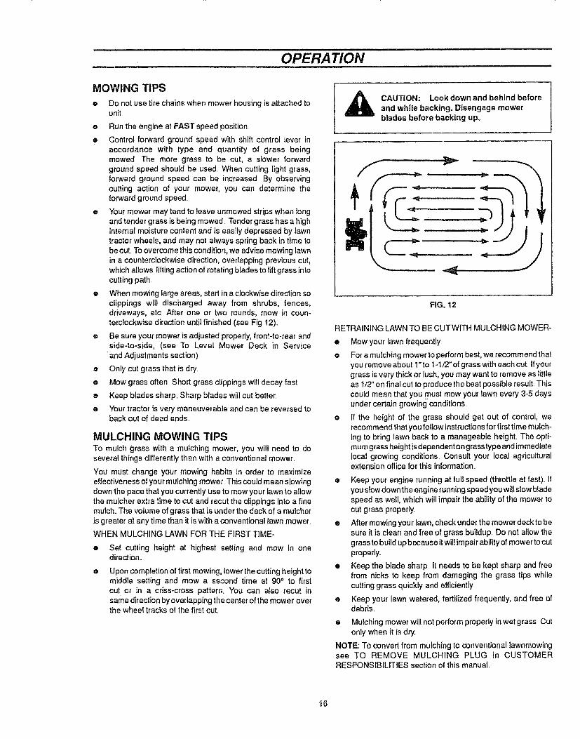
e When mowing large areas, start in a clockwise direction soclippings will discharged away from shrubs, fences,driveways, etc After one or two rounds, mow in coun-terclockwise direction until finished (see Fig 12).,
e Be sure your mower is adjusted properly, front-to-rear andside-to-side, (see To Level Mower Deck in Service
•and Adjustments section)
e Only cut grass that is dry
e Mow grass often Short grass clippings wilt decay fast
e Keep blades sharp. Sharp blades vviflcut better.
e Your tractor is very maneuverable and can be reversed toback out of dead ends.
MULCHING MOWING TIPSTo mulch grass with a mulching mower, you wilt need to doseveral things differently than with a conventional mower.
You must change your mowing habits in order to maximizeeffectiveness of your mulching mower. This could mean siowingdown the pace that you currently use to mow your fawn to allowthe mulcher extra time to cut and recut the clippings into a finemulch_The volume of grass that is under the deck of a mulcheris greater at any time than it is with a conventional lawn mower_
WHEN MULCHING LAWN FOR THE FIRST T1ME-
• Set cutting height at highest setting and mow in onedirection._
e Upon completion of first mowing, lower the cutting height tomiddle setting and mow a second time at 90° to firstcut or in a cfiss-cross pattern. You can also recur insame direction by overlapping the center of the mower overthe wheel tracks of the first cut.
,_ CAUTION: Look down and behind beforeand white backing. Disengage mowerblades before backing upo
FIG. 12
RETRAINING LAWN TO BE CUTWITH MULCHING MOWER-
• Mow your lawn frequently
e For a mulching mower to performbest, we recommend thatyou remove about ! "to 1-1/2" of grass with each cut if yourgrass is very thick or lush, you may want to remove as littleas tt2" on final cut to produce the best possible result. Thiscould mean that you must mow your lawn every 3-5 daysunder certain growing conditions
• If the height of the grass should get out of control, werecommendthat you follow instructions for first time mulch-ing to bring lawn back to a manageable height. The opti-mum grass height isdependent on grass type and immediatelocal growing conditions, Consult your local agriculturalextension office for this information.
• Keep your engine running at full speed (throttleat fast) 11youslow downthe engine running speedyou willslow bfadespeed as well, which will impair the ability of the mower tocut grass properly.
• After mewing your lawn, check under the mower deck to besure it is clean and free of grass buildup. Do not allow thegrass to build up because itwill impair ability of mower to cutproperly,.
• Keep the blade sharp It needs to be kept sharp and freefrom nicks to keep from damaging the grass tips whilecutting grass quickly and efficiently
e Keep your lawn watered, fertilized frequently, and free ofdebris,
• Mulching mower willnot perform properly in wet grass Cutonly when it is dry..
NOTE: To convert from mulching to conventional Iawnmowingsee TO REMOVE MULCHING PLUG in CUSTOMERRESPONSIBILITIES section ot this manual.
16

CUSTOMER RESPONSIBILITIES
GENERAL RECOMMENDATIONS
The warranty on thistractor does not cover items that have beensubjected to operator abuse or negligence To receive full valuefrom warranty, operator must maintain lawn tractor as instructedin this manual
.Some adjustments will need to be made periodically to properlymaintain your uniL
All adjustments in the SERVICE AND ADJUSTMENTS sectionof this manual should be checked at least once each season.
Once a year you should replace spark plug. clean orreplace air filter, and check blades and belts for wear. Anew spark plug and clean air filter assure proper air-fuelmixture and help your engine run better and last longer
BEFORE EACH USE
• Check engine oii level..
o Check brake operation.
• Check tire pressure
e Check for loose tasteners
CUSTOMER
RESPONSIBILITIESSCHEDULE
FILL IN SERVICE DATESAS YOU COMPLETEREGULAR SERVICE
BEFORE EACH USE
AFTER FIRST 5 HOURS+ EVERY 8 HOURS I
iEVERY 25 HOURSEVERY 50 HOURS
t EVERY 100 HOURS
BEGINNING EACH SEASONi ,' t BEFORE STORAGE
J + + i+ . i i
SERVICE DATES
Check Brake Operat!on J = _ ! ! I.......... '..... _ .... .4. = !
Check Tire Pressure " i _ : 1
T Check for Loose Fasteners v" 4' I _
R Sharpen or Replace Mower BIades + 4"3 . , ,_ ____[. ' / ..__
A Lub,oa_+nCha..... I ' + J _ i___4 i !. !° -1 ., _ T_[:T0 Clean Battery and Terminals I _ ii i::_____ _ZZ__----, j_ ....... J" _-_R CheckTransmissi0n Coo!ing t 4" ! J + 1 ! I I
Adjust Blade Belt(s) Tension I _-2-T_ _- ....
Adjust Motion Drive Belt(s) Tension + _...! i I _ ! I .._ ! t i
Check Engine Oil Level 4" _ ! ' + "-'-_- ............ i .... J I
Change Engine Of.!
Clean Air Fi+ter
Clean Air Screen
!,
......... I--- #"
'/'2 , ,
iinspe_ MufflertSpark Arresie; ........ J {............I i
Re#iaceQii Filter (if equipped)- i ! ! ,4,._ I
i i + I
..................t I
+ 4' [ tC ean Eng ne Coo ing Fins i J 2 ; I j I i 'Replace Spark PIug ..... i--- j _ -{ J } '
:l.......................................... | i .......... ...... , _ " "
Replace Air Filter.........Paper Cartridge 1 , ! ! lJ'21 ;i' J'2 ' " ....... -_'---q J ', ' +...... i- ......!-+----j---d-- _
Replace Fuel Filter ! _ I '/ i......................... + i ! • ...............i i I .....
l . t...... I , .
EN
NE
(1) Change more oiler} when operating ur_der a heavy load or in high ambient temperatures
(2) Service more often when operating in dirty or dusty conditions (3) - Replace blades more often when mowing in sandy soil
t7
!
CUSTOMER RESPONSIBILITIES
LUBRICATION CHART
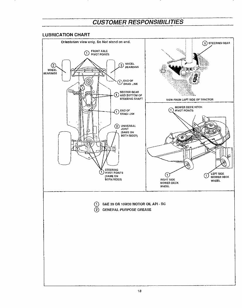
Orientation view only,, Do Not stand on end_ O STEERINGGEAR
Q FRONTAXLEPIVOT POINTS
WHEEL
BEARINGS
(_END OFDRAG LiNK
SECTOR GEARI AND BOTTOM OF
STEER1NG SHAFT
ENDOF
DRAG LINK
UNIVERSALJOINT
(SAME ON
BOTH SIDES)
STEERINGI PIVOT POINTS
(SAME ONBOTH SIDES)
VIEW FROM LEFT SIDE OF TRACTOR
MOWER DECK HITCHPIVOT POINTS
RIGHT SIDEMOWER DECK
WHEEL
EoFTSIDEWER DECK
WHEEL
Q SAE 30 OR 10W30 MOTOR OIL API - SG
@ GENERAL PURPOSE GREASE
t8

CUSTOMER RESPONSIBILITIES
TRACTOR
Always observe safety rules when performing anymaintenance..
BRAKE OPERATION
Your tractor is equipped withan adjustable disc brake To checkbrake operation do the following:
• Stoptractor on a level surface and place shift control leverin NEUTRAL position.
e Depress brake_clutch pedal enough to latch parking brakein 2nd notch.
e Try to push tractor, lf you are unable to push tractor, brakeis too tight and should be loosened (see TO ADJUSTTRACTOR BRAKE in SERVICE AND ADJUSTMENTSsection of this manual.
e Depress brake-clutch pedal enough to latch parking brakein 4th notch_
e Try to push tractor If you are able to push tractor, brake istoo loose and should be tightened (see TO ADJUSTTRACTOR BRAKE in SERVICE AND ADJUSTMENTSsection of this manual.,
During tractor operation, check for stopping distance..If tractorrequires more than six (6) feet stopping distance at high speedin highest gear, the brake must be adjusted (see to ADJUSTTRACTOR BRAKE in SERVICE AND ADJUSTMENTS sectionof this manual),
e Maintain proper air pressure in all tires,, (See"PRODUCTSPECIFICATIONS" on page 3 of this manual),
e Keep tires free of gasoline, oil, or insect controlchemicalswhich can harm rubber.
o Avoid stumps, stones, deep ruts, sharp objects and otherhazards that may cause tire damage
CAUTION: BEFORE PERFORMING ANYSERVICE OR ADJUSTMENTS
• Fully depress brakeoctutch pedal and setparking brake.,
e Place shift control lever in NEUTRALposition,
• Place attachment clutch lever in DISEN-GAGED position,,
e Turn ignition key OFF and remove key°• Make sure the blades and all movtng
parts have completely stopped,• DO NOT handle blades with bare hands.
Wear gloves or wrap blade with news-paper or other material while removingor Installing blade.
BLADE CAREFor best results mower blades must be kept sharp The bladescan be sharpened with a file or on a grindingwheel. We suggest they be sharpened or replaced after every25 hours or mowing, Check blades more often if mowing insandy conditions.,
BLADEMOUNTINGSCREWS
SHARPEDGE
Fig, 13
BENTTIPEDGE
BLADE
SPRINGWASHERS
GRADE 5 QBOLT SHOWN MOUNTING
SCREW
Fig° 14
• Do not attempt to sharpen blades while they are on mower,
e Replace bent or damagedbladeso
BLADE REMOVAL (See Figs. 13 and 14)
• Remove mowerdeck (seeTO REMOVE MOWER DECKin this section),,
• Remove blade mounting hardware securing blade
• Install new blade with bent tip edges up.. Blade wiUnot cutif bent tip edges are not up toward top of mower deck,
e Secure biade to mower deck with mounting hardwareremoved earlier_ Be sure all parts are re-assembled inproper order as shown.
e Tighten blade mounting bolts securely, "We recommendusing a 10 inch wrench or torque wrench, If atorque wrenchis used, torque bolts to between 30 -35 ft lbs).
IMPORTANT: Blade mounting bolts are Grade 5 heat treated asshown in Fig° 14 inset.
!9

CUSTOMER RESPONSIBILITIES
TO SHARPEN BLADE (See Fig= 15)
Care should be taken to keep blade balanced An unbalancedblade wilt cause excessive vibration and eventual damage tomower and engine
• Blade can be sharpened witha file or on a grinding wheelDo not attempt to sharpen while on mower.
e Place center hole of blade over head of the nail or end ofa screwdriver clamped horizontally in a vice. If blade isbalanced, it should remain in a horizontal position. If eitherend of the blade moves downward_ sharpen heavy end untilthe blade is batanced
TO REMOVE MULCHING PLUG
(See FIG. 16)
Your tractor has a mulching kit installed on the mower deck. Toconvert from mulching to regular lawnmowing, the mulchingplug may be removed as follows:
e Remove the two 5/16-18 wing nuts and 5/16 lock washersfrom atop of mulching plug installed inside mower deckchute,
• The two 5/16-18 x ,75 inch carriage bolts wil! drop and canbe easily removed from underneath the mulching plugand toe guard.
o Remove mulching plug from mower chute DO NOTremove toe guard. Your tractor is now ready to be used asa conventional mower.
® Store mulching plug and hardware ina safe placelor futureuse.
• To reinstall plug reverse the above steps
BATTERY (See Fig. 17)
Your tractorhas a battery charging system which issufficient fornormal use However, periodic charging of battery with anautomotive charger will extend its life.
• The acid level in each battery should be even with bottomsof vent wells Add only distilled or iron free water if neces-saP/ Do not over fitl
• Keep battery and terminals clean,.
• Keep battery bolts tight,
_, Keep vent caps and small vent holes in caps open
e Recharge at 6 amps for 1 hour.
TO CLEAN BATTERY AND TERMINALS -
Corrosion and dirt on battery and terminals can cause slowbattery power drain.
• Remove terminal guard (if so equipped),
• Disconnect BLACK battery cable first then RED batterycable and remove battery from tractor (see To RemoveBattery in Assembly section of this manual),
e Wash battery with solution of four tablespoons of bakingsoda to one gallon of water Be careful not to get sodasolution into cells.
• Rinse battery' withplain water and dry.
• Clean terminals and batterycable endswith wirebrush untilbright
2O
BLADE
CENTER HOLE
Fig. 15
MULCHING PLUG
TOEGUARD
CARRIAGE X.75
Fig. 16
VENT CAP\
VENT
BATTERYCELL ACIDLEVEL
FIG. 17
• Coat terminals with grease or petroleum jelly.
• Reinstall battery (see TO INSTALL BATTERY inASSEMBLY section of this manual),.
V-BELTS
Check V-belts for deterioration and wear after 100 hours and
replace if required The mower blade drive belt and tractor drivebelts can be adjusted to provide longer belt life (see TO ADJUSTBLADE DRIVE BELT orTO ADJUST TRACTOR DRIVE BELTin SERVICE AND ADJUSTMENTS section of this manual)
TRANSAXLE COOLING
Keep transaxle free from build-up of dirt and chaff which canrestrictcooling
CUSTOMER RESPONSIBILITIES
ENGINE
LUBRICATION
Read ENGINE instructions in this section and OPERATIONsection of this manual before trying to start engine
NOTE: Be sure oil has been added to engine crankcasebefore trying to start engine.
OIL RECOMMENDATIONS
Onty use high quality detergent oil rated with APf serviceclassification SG Select the oil's SAE viscosity g fade accordingto your expected operating temperature:
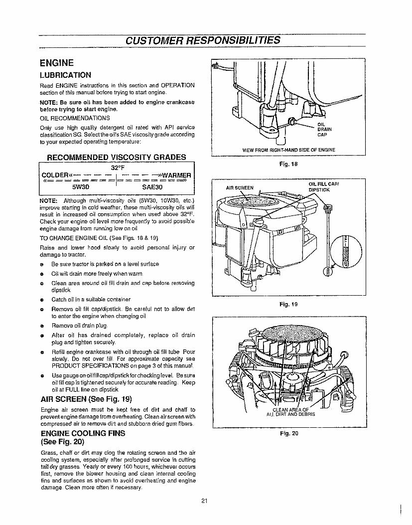
RECOMMENDED VISCOSITY GRADES
32°F
COLDER_€ I --_WARMER5W30 SAE30
NOTE: Although multi-viscosity oils (5W30, 10W30, etc..)improve starting in cold weather, these multi-viscosity oils willresult in increased oil consumption when used above 32°F.Check your engine oi] level more frequently to avoid possibleengine damage from running low on oil
TO CHANGE ENGINE OIL (See Figs. 18 & 19)
Raise and lower hood slowly to avoid personal injury ordamage to tractor.
e Be sure tractor is parked on a level surface
e Oitwill drain more freely when warm.
e Clean area around oil fill drain and cap before removingdipstick.
e Catch oil in a suitable container
e Remove oil fitt cap/dipstick Be careful not to allow dirtto enter the engine when changing oil
• Remove oii drain plug.
• After oil has drained completely, replace oil drainplug and tighten securely.
• Refill engine crankcase with oil through oil fill tube Pourslowly° Do not over fill For approximate capacity seePRODUCT SPECIFICATIONS on page 3 of this manual.
• Use gauge on oi!fillcap/dipstickfor checking level.. Be sureoil fill cap istightened securely for accurate reading. Keepoil at FULL line on dipstick
AIR SCREEN (See Fig. '19)
Engine air screen must be kept free of dirt and chaff topreventengine damage from overheating. Clean air screen withcompressed air to remove dirt and stubborn dried gum fibers
ENGINE COOLING FINS
(See Fig. 20)
Grass, chaff or dirt may clog the rotating screen and the aircooling system, especially after prolonged service in cuttingtall dry grasses Yearly or every 100 hours, whichever occursfirst, remove the blower housing and clean internal coolinglins and surfaces as shown to avoid overheating and enginedamage. Clean more often if necessary
2I
VIEW FROM RIGHT-HAND SIDE OF ENGINE
Fig, 18
I OIL FILL CAP/AIR SCREEN DIPSTICK
Fig. 19
CLEAN AREA OFALL DIRT AND DEBRIS
Flg. 20
i

CUSTOMER RESPONSIBILITIES
AIR FILTER (See Fig. 21)
"Your engine will not run properly and may be damaged byusing a dirty air filter. Clean foam pre-cteaner element afterevery 25 hours of operation or every season. Service papercartridge every 100 hours orevery season, whichever occursfirst, Service air cleaner mote often under dusty conditions..
e.. Remove knobs and air cleaner cover
TO SERVICE FOAM PRE-CLEANER-
• Remove foam pre-cleaner by sliding itoff the cartridge.
e Wash foam pre-cleaner in liquiddetergent and water
• Squeeze foam pre_cleaner dry in a clean cloth..
• Saturate foam pre-cleaner in engine oil. Wrapfoam pre-cleaner in clean, absorbent cloth and squeeze to removeALL EXCESS oil
e Reinstall foam pre_cieanerover cartridge.
e Reinstall air cleaner cover and tighten knobs securely
TO SERVICE CARTRIDGE-
e Remove wing nuts and cover plate..
e Remove cartridge and clean by tapping gently on flatsurface..
o If very dirty, replace or wash in a non-sudsing detergentand warm water solution Rinse thoroughly with waterfrom inside out untilwater runs clear. Let cartridge drythoroughly before using.
• Reinstall cartridge, cover plate and wing nuts.
e Reinstall air cleaner cover and tighten knob securely
IMPORTANT: PETROLEUM SOLVENTS, SUCH ASKEROSENE, ARE NOT TO BE USED TO CLEAN CAR-TRIDGE. DO NOT OIL CARTRIDGE. DO NOT USE PRES-SURIZED AIR TO CLEAN OR DRY CARTRIDGE
MUFFLER
Inspect and replace corroded muffler and spark arrester (if soequipped) as itcould create a fire hazard and/or damage.
SPARK PLUGS
Replace spark plugs at the beginning of each mowingseason or after every 100 hours of use, whichever comesfirst. Spark p!ug type and gap setting is shown in PRODUCTSPECIFICATIONS on page 3 of this manual.
IN-LINE FUEL FILTER (See Fig. 22)
Fuel filter should be replaced once each season. If fuel filterbecomes clogged, obstructing fuel flow to carburetor, re-placement is required. Make sure new filter is installed withthe IN marking toward the tank and the OUT marking towardthe engine Check fuel system components frequently andreplace any parts showing wear or cracks
• With engine coo!, remove filter and plug fuel line sections.
@
@
@
Place new fuel filter inpositioninfuel line witharrow pointingtowards carburetor.
Be sure there are no fuel line leaks and clamps are properlypositioned..
immediately wipe up any spilled gasoline.
22
KNOBS
_CLEANERCOVER
WING NUTS
COVER PL/_TE
CARTRIDGE
Fig. 21
FUEL FILTER
CLAMP
CLAMP
Fig° 22
CLEANING
@ Clean engine, battery, seat, transaxle, finish, etc. of allforeign matter.
@ Keep finished surfaces and wheels free of all gasoline, oil,etc
@ Protect painted surfaces with automotive lype wax,
We do not recommend using a garden hose to clean yourtractor unless electrical system, muffler, air filter andcarburetor are covered to keep water ouL Water in engine canshorten engine life..

SERVICE AND ADJUSTMENTS
CAUTION: BEFORE PERFORMING ANY SERVICE OR ADJUSTMENTS
e Depress brake-clutch pedal and set parking brake°
® Place shift control lever in NEUTRAL position_
e Place attachment clutch lever in DISENGAGED position,
e Turn ignition key OFF and remove key,
® Make sure the blades and all moving parts have completely stopped°
TRACTORTO REMOVE MOWER DECK
Remove mower deck from right side of tractor,
e Place cutting height adjustment pedal in lowest cuttingposition by moving memory rod to position 1 and pressingpedal latch to release cutting height adjustment pedal
® Turn |font wheels all the way to the left to allow mower deckhitch to slide past right front wheel,
• Remove hairpin cotter from mower deck hitch andremovedeck hitch rod from top holes of the front mountingbracket (see Fig° 23A).,
• Lower deck hitch.,
• Remove hairpin cotter and Flatwasher from hanger pin ofrightrear lift arm and slide off right mower deck lift bracket(see Fig, 23B).
e Remove hairpincotter and Flatwasher from hanger pin ofleft rear lift arm and slide off left mower deck liftbracket (seeFig 23B),
e Pull lower engine pulley belt guides away from pulley (seeFig. 24)_
e Move mower deck forward and remove mower deck drive
belt from lower engine pulley, Reposition belt guides_
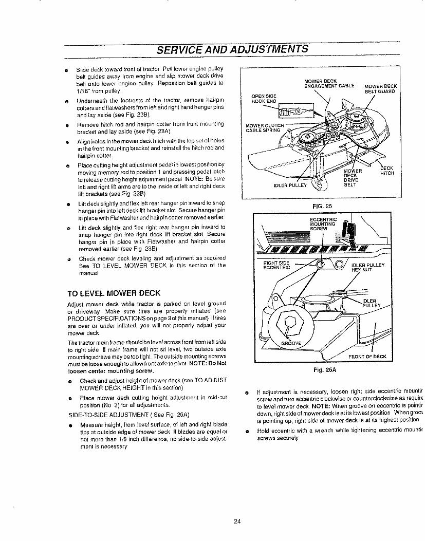
e Disconnect mower deck engagement cable from mowerclutch cable spring (see Fig 25)
e Place cutting height adjustment pedal in highest cuttingposition°
• Pull mower deck out from under right side of tractor
TO INSTALL MOWER DECK
@ Place cutting height adjustment in highest position bypressing cutting height adjustment pedal all the way downuntil it latches, ifcutting height is not in highest position, thedeck brackets will hit the lift arms while sliding the deckunder the tractor.
• Place mower deck on right side of tractor withchute deflector away from tractor.
• Turn front wheels of tractor to maximum left turn,
e Lift deck hitch and slide deck under tractorto a centeredposition
@ From left side of tractor, slide deck rearward,,Then connect
mower deck engagement cable to mower clutch cablespring (see Fig. 25). Be sure open side of spring end ispointeddown (see Fig., 25 inset).
FRONTMOUNTINGBRACKET
HAIRPIN
MOWERDECKHITCH
VIEW FROM FROt_I "OF TRACTOR
FIG. 23A
MOWER DECKLIFT BRACKET(RIGHT SIDE)
FLATWASHER \\_, I
VIEW FROM RIGHT SIDE OF TRACTOR
FIG. 23B
LOWER ENGINEPULLEY BELT GUIDES
LOWERENGINE PULLEY
FIG,, 24
23
SERVICE AND ADJUSTMENTS
® Slide deck toward front of tractor Puff lower engine pulley
belt guides away from engine and slip mower deck drive
be_t onto lower engine puIley Reposition be_t guides to
1/16+' from pulley.
• Underneath the footrests of the tractor, remove hairpincotters and flatwashers from left and right hand hang er pins
and _ay aside (see Fig 23B).
e Remove hitch rod and hairpin cotter from trent mounting
bracket and lay aside (see Fig. 23A)
® Align holes in the mower deck hitch with the top set of holesin the front mounting bracket and reinstafl the hitch rod and
hairpin cotter
• Place cutting height adjustment peda_ in lowest position by
moving memory rod to position 1 and pressing pedal la',chto release cutting height adjustment pedal NOTE: Be sure
left and right lift arms are to the inside of Ieft and right decktift brackets (see Fig 23B).
• Lift deck slightly and flex left rear hanger pin inward to s nap
hanger pin into left deck rift bracket slot. Secure hanger pin
in place with Flatwasher and hairpin cotter removed earlier
• Lift deck slightly and flex right rear hanger pin inward tosnap hanger pin into right deck lift bracket slot Secure
hanger pin !n place with Flatwasher and hairpin cotterremoved earlier (see Fig. 23B)
• Check mower deck reveling and adjustment as requiredSee TO LEVEL MOWER DECK in this section of the
manual
MOWER DECKENGAGEMENTCABLE MOWERDECK
%. BELT GUARDOPEN SIDEHOOK END
MOWERCABLESPRING
IDLER PULLEY
:KMOWERDECK H_TCHDRWEBELT
FIG,+ 25
TO LEVEL MOWER DECK
Adjust mower deck while tractor is parked on level groundor driveway Make sure tires are properly inflated (seePRODUCTSPECfF1CATtONSonpage3ofthis manual) lftires
are over or under inflated, you will not proper_y adjust yourmower deck.
The tractor main frame should be Ievel across front from teft side
to right side If main frame will not sit level, two outside axlemounting screws may betoo tight. The outside mounting screwsmust be loose enough to allow front axle to pivot. NOTE: Do Notloosen center mounting screw.
e Check and adjust height of mower deck (see TO ADJUSTMOWER DECK HEIGHT in this section)
• Place mower deck cutting height adjustment in mid-cut
posit{on (No 3) for all adjustments
SiDE-TO+SIDE ADJUSTMENT ( See Fig 26A)
• Measure height, from leve_ surface, of teft and right blade
tips at outside edge of mower deck If blades are equa+ ornot more than 1/8 inch difference, no side+to+side adjust-
ment is necessary
Fig,.26A
• If adiustment is necessary, !oosen right side eccentric mountirscrew and turnecce_tric clockwise or counterclockwise as requir_to revel mower deck, NOTE: When groove on eccentric is pointirdown, rightside of mower deck is at its lowest position When groinis pointing up, right side of mower deck is at its highest position
• Hold eccentric with a wrench while tightening eccentric mountir
screws secure{y
24
SERVICE AND ADJUSTMENTS
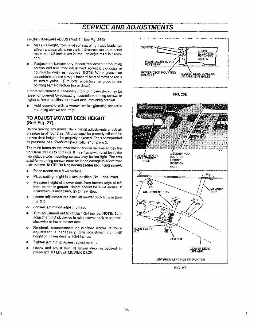
FRONT_TO-REAR ADJUSTMENT ( See Fig 26B)
• Measure height, from level surface, of right side blade tipsat front and rearof mower deck. Ifdistances are equalor notmore than lib inch lower in front, no adiustment is neces-sary..
o If adjustment is necessary, loosen front eccentric mountingscrews and turn front adjustment eccentric clockwise orcounterclockwise as required. NOTE: When groove oneccentric is pointed straight forward, front of mower deck isat lowest point. Turn both eccentrics so grooves arepointing same direction (up or down).
If more adjustment is necessary, front of mower deck may beraised or lowered by relocating eccentric mounting screws inhigher or lower position on mower deck mounting bracket.
e Hold eccentric with a wrench while tightening eccentricmounting screws securely..
TO ADJUST MOWER DECK HEIGHT(See Fig. 27)
Before making any mower deck height adjustments check airpressure in all four tires.. All tires must be properly inflated formower deck height to be properly adiusted.. For recommendedair pressure, see "Product Specifications" on page 3o
The main frame on the lawn tractor should be level across thefront from left side to right side.. If main frame will not sit level, thetwo outstde axle mounting screws may be too tight. The twooutside mounting screws must be loose enough to allow frontaxle to pivot, NOTE: Do Not loosen center mounting screw.
• Place tractor on a level surface..
o
@
O
O
o
Place cutting height in lowest position (No. t see inset).
Measure height of mower deck from bottom edge of leftfront corner to ground. Height should be t-3/4 inches, ifadjustment is necessary, go to next step..
Locate adjustment nut near left mower deck lift arm (seeFig. 27)°
Loosen jam nut on adjustment rod
Turn adjustment nut to obtain 1-3/4 inches. NOTE: Turnadjustment nut clockwise to raise mower deck or counteFclockwise to lower mower deck.
e Re-check measurement as outlined above.. If more
adjustment is necessary, turn adjustment nut untilheight ol mower deck is 1-3/4 inches..
• Tighten jam nut up against adjustment nut
• Check and adjust level of mower deck as outlined inparagraph TO LEVEL MOWER .DECK.
QROOVE__ _ , _,L__ __ FRONT /' _''"_,,,._.._._Z_IM_I_ _ ECCENTRIC l
_,,'T"'8_. 1t MOUNTING )/ ,,_ u\! t SCREW |
FRO_fT ADJUSTMENT ./'_ '_.=,_ }
EC CENT RIC / }'_-""_\
MOWER DECK MOUNTING MOWER DECK LEVELIN GBRACKET ADJUSTMENT HOLES
FIG. 26B
MEMORY ROD
CUTTING HEIGHT (CUTTINGADJUSTMENTPEDAL HEIGHT
PosmoNNO.,t)
VIEMORY
ADJUSTMENTNUT
JAM NUT
MOWER DECKLIFT ARM
ViEW FROM LEFT SIDE OF TRACTOR
FIG. 27
25

SERVICE AND ADJUSTMENTS
TO ADJUST BLADE DRIVE BELT
(See Fig. 28)
When mower blade drive belt slips and blades wilt not turnat full speed when mowing, the blade drive belt should be
tightened,,
e Place attachment clutch lever in DISENGAGED posi-tion,,
Loosen idler pulley hex nut
e Slide idler pulley toward rear of mower deck to lightenbelt NOTE: Only a small amount of movement shouldbe required
e Re-tighten hex nut on idler pultey
e To check adjustment:
a. Start.engine and place throttle control lever inposition FAST
b. Place attachment clutch{ever inENGAGED positionand allow sufficient time for blades to run to fuJlspeed,then place attachment clutch ]ever in DISENGAGEDposition. Blades should stop within a few seconds andremain stopped If blades do not stop or tend to creep,adjustment is too tight
To loosen blade drive belt0loosen idlerpulley and movetoward front of mower deck..
BLADE BRAKE ADJUSTMENT
(See Fig. 28)Blade brakes should stop mower blades when attachmentclutch lever is in DISENGAGED position. Blade brake padsshould not come in contact with quill assemblies whenattachment clutch lever is in ENGAGED position.
e Place cutting height adjustment in lowest cut position(No,t),.
TO CHECK RIGHT HAND BRAKE
® Move attachment clutch lever backward to DISEN-GAGED position.
e Begin to move attachment clutch lever forward towardENGAGED position and check distance lever movesbefore brake pad, on right hand quitl assembly, beginsto move.
Attachment clutch lever should move at least 3t4 inch,but not more than 1 inch, before brake pad begins tomove..
• If the distance is not between 3/4 and t inch, (see TOADJUST RIGHT HAND BRAKE below).
TO ADJUST RIGHT HAND BRAKE -
e Note which one of five holes on front of idler armextension is used for attaching mower dutch cablespring (see Fig..28, inset B).
e If distance is more than t inch, move mowerclutch cable spring to a hole toward bolts holding idlerarm extension.
If distance is less than 3/4 inch, move mower clutchcable spring to a hole toward free end of idler arm ex-tension
• Re=checkright hand brake and adjust if required..
CABLE
MOWER DECI(ENGAGEMENTCABLE
MOWER DECKBELT"GUARD
RIGHT HANDQUILL
MOWER CLUTCHCABLE SPRING
iDLER ARMEXTENSION
IDLER PULLEYHEX NUT
LOCI(NUT
_RDECKDRIVE
INSET B
Fig. 28
TO CHECK LEFT HAND BRAKE
e Place attachment cSutch lever in DISENGAGED posi-tion
o Locknut, on end of brake rod, should be approximately1/8 inch from brake pad mounting bracket with left handbrake pad against pulley of left hand quill assembly (SeeFig. 2B, inset A).
TO ADJUST LEFT HAND BRAKE-
• Adjust [ocknut if necessary
26

SERVICE AND ADJUSTMENTS
TO REPLACE MOWER BLADE DRIVE BELT
(See Fig+ 29)
e Remove mower deck (see TO REMOVE MOWER DECKin this section,
e Remove mower deck belt guard
• Note position of belt retainer on idler pulley so itcan be canbe repositioned properly after belt installation Loosen idlerpulley.,
® Remove old belt and replace with a new original equipmentbelt
e Reinstall belt guard,.
@ Reposition belt retainer and re-tighten idler pulley,,
• Reinstatl mower deck assembly,
• Adjust belt (see TO ADJUST TRACTOR DRIVE BELTbelow)+
TO ADJUST TRACTOR DRIVE BELT(See Figs. 30A and 30B)
The drive belt is kept tight by a spring attached to the brake-clutch pedal assembly When the drive beft is properlyadjusted, the brake+clutch pedal shoutd appear as shown in fullyreleased position.,
® The brake-clutch pedal should appear as shown in Fig, 30Awhen in the futly reteased position, iI not, then the foftowingadjustment is necessary.
e Depress the brake-clutch pedal enough to latch the parkingbrake in the 3rd notch
e Loosen clutching idler pulley mounting screw,
e If brake+clutch pedal was too far forward, slide idler pulleyin toward engine pulley, If pedal was too far rearward, slideidlerpultey away from engine pulley.
e Re-tighten idler pulley mounting screw., NOTE: Beltretainer should point toward position where running boardmeets main frame,
• Release brake+clutch pedal and re-check pedal for properposition and readjust if necessary.
e Check tractor brake adjustment (see TO ADJUSTTRACTOR BRAKE in this section),
MOWER DECKENGAGEMENT CABLE
MOWER CLUTCHCABLE SPRING
IDLER PULLEYBELT RETAINER
PULLEYMOWER DECKDRIVE _BELT
Fig+29
BRAKE,-CLUTCH
PEDAL
Fig, 30A
BELT RETAINERCLUTCHINGIDLERPULLEYMOUNTINGSCREW
CLUTCHING iDLER PULLEY
BRAKE-CLUTCHPEDAL
PARKING BRAKELEVER
3rdNOTCH
27
Fig,,30B
i,

SERVICE AND ADJUSTMENTS
TO REPLACE TRACTOR DRIVE BELT
(See Figs. 31 and 32)Your tractor uses v-be Its made of special compounds, if any belt
becomes worn or breaks, replace will'} original equipment be_t
(see REPAIR PARTS section of this manual) NEVER USE ASUBSTITUTE.
e Remove mower deck (see TO REMOVE MOWER DECK
in this section).
• Fully depress brake-clutch pedal and set parking brake
• Loosen clutching idler pulley mounting screw
• Pull belt retainer away from pulley and remove belt from
clutching idler pulley.
e Remove belt trom engine pulley
e Remove belt from transaxle pulley
• Replace belt by reversing above instructions Be sure beltis installed to inside of upper engine pulley belt guide
e Before repositioning and tightening clutching idler pulley
and belt retainer, adjust tractor drive belt (see TO ADJUSTTRACTOR DRIVE BELT in this section)
® Check tractor brake adjustment (see TO ADJUSTTRACTOR BRAKE in this section)
TO ADJUST SEAT
(See Fig. 33)Tile seat can be adjusted forward or rearward to desired
operator's position
e Raise rear of seat to horizontal position
® Loosen (do not remove) four hex head screws in seat plate
e Pull up on seat to move it toward rear of tractor, or pushdown on seat to move to toward tront of tractor
• Tighten hex head screws in seat plate.
If more adjustment is required:
e Remove seat and seat plate.
• Install seat and seat plate in either forward or backward
holes of seat support bracket.
Orientation view onty Do Not stand on end,
LOWERENGINE PULLEY/ .... ; BELT GUIDES f _,
LOWER/ I A t IENGINE ,,_ i i ..... _--J lPULLEY
./-_1__ _ I(( "',,_ ENGINE
' l)_,/ t \, PULLEY
CLUTCHING { It )rULER' t ; LTGU,D
Fig_ 31
IDLER
PULLEY
CLUTCHINGIDLER PULLEYMOUNTINGSCREW
II
Fig. 32
SEAT
HEXHEADSCREWS
SEATPLA3"E
SEAT PLATE _"_"_
BRACKETMOUNTINGHOLES
SEAT PLATEBRACKET
28
Fig. 33
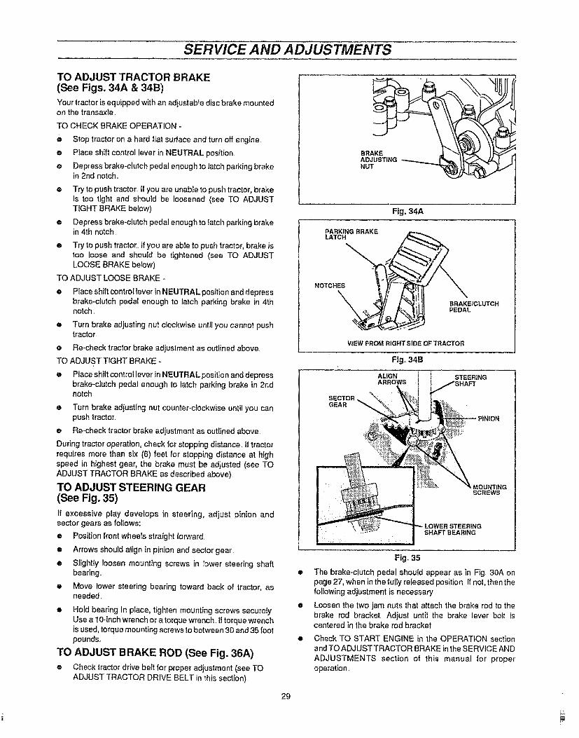
SERVICE AND ADJUSTMENTS
TO ADJUST TRACTOR BRAKE(See Figs. 34A & 34B)
Your tractor is equipped with an adjustable disc brake mountedon the transaxle
TO CHECK BRAKE OPERATION *
0 Stop tractor on a hard flat surface and turn off engine.
• Place shift control lever in NEUTRAL position
e Depress brake-clutch pedal enough to latch parking brakein 2rid notch,,
O
o
o
TO
o
Try to push tractor.. If you are unable to push tractor, brakeis too tight and should be loosened (see TO ADJUSTTIGHT BRAKE below).
Depress brake-clutch pedaI enough to _atchparking brakein 4th notch.
Try to push tractor. If you are able to push tractor, brake istoo loose and should be tightened (see TO ADJUSTLOOSE BRAKE below)
ADJUST LOOSE BRAKE -
Place shift control lever in NEUTRAL position and depressbrake-clutch pedal enough to latch parking brake in 4thnotch.
e Turn brake adjusting nut clockwise until you cannot pushtractor.
e Re-check tractor brake adjustment as outlined above.
TO ADJUST TIGHT BRAKE -
e Place shift control lever in NEUTRAL position and depressbrake-clutch pedal enough to latch parking brake in 2ndnotch.
e Turn brake adjusting nut counter-clockwise until you canpush tractor.,
e Re-checktractor brake adjustment as outlined above.
During tractor operation, check for stopping distance. If tractorrequires more than six (6) feet for stopping distance at highspeed in highest gear, the brake must be adjusted (see TOADJUST TRACTOR BRAKE as described above).
TO ADJUST STEERING GEAR(See Fig. 35)
If excessive play develops in steering, adjust pinion andsector gears as follows:
• Position front wheels straight forward
• Arrows should align in pinion and sector gear
• Siightly loosen mounting screws in lower steering shaftbearing..
• Move lower steering bearing toward back of tractor, asneeded,
• Hold bearing in place, tighten mounting screws securely.Use a 10-inch wrench or a torque wrench if torque wrenchis used, torque mounting screws to between 30 and 35 footpounds.
TO ADJUST BRAKE ROD (See Fig. 36A)
® Check tractor drive belt for proper adjustment (see TOADJUST TRACTOR DRIVE BELT in this section).
29
BRAKEADJUSTINGNUT
Fig. 34A
PARKING BRAKELATCH
NOTCHES
BRAKEICLUTCHPEDAL
VIEW FROM RIGHT SIDE OF TRACTOR
Ftg_ 34B
ALIGN i STEERINGARROWS
,MOUNTINGSCREWS
SHAFT BEARING
Fig° 35
• The brake-clutch pedal shouid appear as _n Fig, 30A onpage 27, when in the fully released position ifnot, then thefollowing adjustment is necessary.
e Loosen the two jam nuts that attach the brake rod to thebrake rod bracket, Adjust until the brake lever bolt iscentered in the brake rod bracket
• Check TO START ENGINE in the OPERATION sectionand TO ADJUST TRACTOR BRAKE in the SERVICE AND
ADJUSTMENTS section of this manual for properoperation.
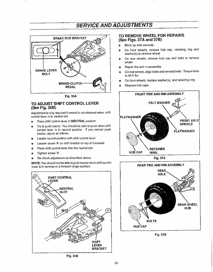
SERVICE AND ADJUSTMENTS
Fig. 36A
TO ADJUST SHIFT CONTROL LEVER(See Fig. 36B)Adjustment is only required if neutra! is not obtainedwhen shiftcontrol lever is in neutral slot
o Place shift control lever in NEUTRAL position,
e Try to push tractor "Youshould be able to push when shiftcontrol lever is in neutral position If you cannot push
,,tractor, adjust as fotiows
e Locate neutra! position with shift control lever
e Loosen screw'A' on shift bracket on top of transaxle
e Place shift control lever into the neutral slot
e Tighten screw 'AL
e Re-check adjustment as described above
NOTE: You should not be able to push tractor when shift controllever iS in reverse or a forward range position,,
LEVERBRACKET
Fig. 36B
TO REMOVE WHEEL FOR REPAIRS(See Figs. 37A and 37B)
e Block up axle securely,
e On front wheels, remove hub cap, retaining ring and
washer(s) to remove wheel,
• On rear wheels, remove hub cap and bolts to removewheel,
e Repair tire and re-assemble
e On rear wheels,align holes and reinstaflbolts, Torque boltsto 50 ft Ibs
• On front wheels, replace washer(s), and retaining ring
e Replace hubcaps.
FRONT TIRE AND RIM ASSEMBLY
jJ
FELT WASHER
FLATWASHERFRONT AXLESPINDLE
FLATWASHER
RETAINERHUB CAP RING
Figo37A
REAR TIRE AND RIM ASSEMBLY
REARAXLE
REAR WHEELHUB
BOLTS
HUB CAP
Fig. 37B
30
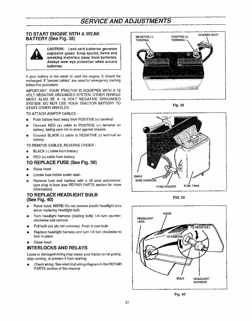
SERVICE AND ADJUSTMENTS
TO START ENGINE WITH A WEAKBATTERY (See Fig. 38)
CAUTION: Lead-acid batteries generateexplosive gases, Keep sparks, flame andsmoking materials away from batteries.Always wear eye protection when aroundbatteries°
II your battery is too weak to start the engine, it should berecharged. If "jumper cables" are used for emergency startingfollow this procedure..
IMPORTANT: YOUR TRACTOR IS EQU1PPED WITH A 12VOLT NEGATIVE GROUNDED SYSTEM. OTHER VEHICLEMUST ALSO BE A 12 VOLT NEGATIVE GROUNDEDSYSTEM. DO NOT USE YOUR TRACTOR BATTERY TOSTART OTHER VEHICLES
TO ATTACH JUMPER CABLES -
• Push battery boot away from POSITIVE (+) terminal.
e Connect RED (+) cable to POSITIVE (+) terminal onbattery, taking care not to short against chassis..
• Connect BLACK (-) cable to NEGATIVE (-) terminal onbattery.
TO REMOVE CABLES, REVERSE ORDER -
e BLACK (-) cabte from battery
e RED (+)cable from battery.
TO REPLACE FUSE (See Fig. 39)
• Raise hood.
e Locate fuse holder under dash,
e Remove fuse and replace with a t5 amp automotive-type plug in fuse (see REPAIR PARTS section for moreintormation),
TO REPLACE HEADLIGHT BULB(See Fig. 40)
• Raise hood, NOTE: Do not remove plastic headlight lenswhen replacing headlight bulb
e Turn headlight harness (holding bulb) !/4 turn counter-clockwise and remove
• Pull bulb out (do not unscrew) Push in new bulb
e Replace headlight harness and turn 1/4 turn clockwise tolock in place..
e Close hood..
INTERLOCKS AND RELAYS
Loose or damaged wiring may cause your tractor to run poorly,
stop running, or prevent it from starting.
• Check wiring See electrical wiring diagram in the REPAIRPARTS section of this manual.
NEGATIVE {-)TERMINAL
POSITIVE (*)TERMINAL
RUBBER BOOT
Fig. 38
DASH
W1REHARNESS
FUSE HOLDER FUELTANK
FIG. 39
HOOD
HEADLIGHTLENS
BULB HEADUGHTHARNESS
Fig. 40
31

SERVICE AND ADJUSTMENTS
TO REMOVE HOOD (See Figs. 41 and 42)
• Raise hood.
e Disconnect headlight wire harness connector
e Remove screw used to attach hood tanyard to front of
engine Hold hood securely to prevent hood from failing
e Remove clevis pins, flatwashers and hairpins used toattach hood to mounting brackets
e To reinstall reverse above procedure
ENGINETO ADJUST CHOKE CONTROL(See Fig. 43)The choke control has beenpreset at factory and adjustmentshould not be necessary, Check adjustment as describedbelow before loosening clamp screw If adjustment isnecessary,proceed as foJ!ows
• Move choke control to '*CHOKE" position Carburetorchoke should be closed tf not choke needs to beadjusted.
• Place control lever in "CHOKE" position, Loosen casingciamp screw
• Move casing and wire until choke is completely closed
® Tighten casing clamp screw
HEADLIGHT WIREHARNESS CONNECTOR
HOOD MOUNTINGBRACKET
ViEW FROM RIGHT SiDE OF TRACTOR
HOOD
FLATWASHER
HAIRPINHOOD MOUNTINGBRACKET
VIEW FROM RIGHT SIDE OF TRACTOR
F|g, 41
FRONT OF
HOOD LANYABD
SCREW
Fig. 42
CHOKE CLOSED
CHOKE LEVER
32
CLAMPSCREW
Fig. 43

SERVICE AND ADJUSTMENTS
THROTTLE CONTROl. ADJUSTMENT(See Fig. 44)The throttle control has been preset at factory andadjustmentshould not be necessary. Check adjustment a_'_"describedbelow before loosening clamp screw. If adj_._tment isnecessary, proceed as foltows.
o Engine speed is controlled my movement of the throttlecontrol lever..
o Move control "B" to 'FAST" position..
® Swivel"C" should be against side of quarter circle.
TO ADJUST-
e Loosen casing cramp screw "A"o
e Move casing and wire in direction shown until swivel isagainst side of quarter circle_
• Re-tighten casing clamp screw "A"..
CARBURETOR ADJUSTMENTS
(See Fig. 45)Minor carburetor adjustment may be required to compensatefor differences in fuel, temperature, altitude or load.
NOTE: The air cleaner must be assembled to carburetor when
running engine..
INITIAL ADJUSTMENT
® Gently turn the id]e mixture screw clockwise until itcloses. Turning screw in too far may damage it.
e Next turn idle mixture screw 1-1/2 turns counterclockwise.
This initial adjustment will permit the engine to be startedand warmed up (approximately 5 minutes) prior to finaladjustment.
FINAL ADJUSTMENT
e Start engine and place throttle control in IDLE or SLOWposition.
e Hold throttle lever against idle stop, and adjust idle speedscrewto obtain 1200 to i400 RPM
• While still holding throttle lever, turn idle mixture screwslowly clockwise (lean mixture) until engine j.q_ starts toslow.
• Still holding lever, turn screw slowly counterclockwise(rich mixture) until engine speed "ujg_starts to slow.
• Turn screw to midpoint between rich and lean.
• Adjust idle speed screw to obtain 900 to 1200 RPM
• Release lever.
• If the engine does not accelerate properly, re-adjustcarburetor to a slightly richer mixture.
0
CIRCLE
Fig, 44
IDLE SPEEDADJUSTING
SCREW
THROTTLE LEVER
FIXED MAIN JETCOVER(HIGH
SPEED)
IDLE MIXTURESCREW
Fig° 45
33

TROUBLESHOOTING POIAITS
PROBLEM
Will not start 1234,5,.
6+7.
a
9.
10..
Hard to start 1.2,3.
4.
5678,
Engine will not 1.
turn over 23.45.67,8,9,
t,
Engine clicks but 2,,wallnot start 3
4
1
Loss of power 23.4+
5678,9
t01112,!31415
Excessive 2,vibration 3
Unit will not 1.
propel itself whenclutch is engaged 2.
3
CAUSE
Out of fuel
Engine not "CHOKED" properly.Engine flooded.Bad spark plug..Dirty air filterDirty fuelfilterWater in fueL.
Loose or damaged wiringCarburetor out of adjustmentEngine valves out of adjustment
Dirty air filterBad spark plugWeak or dead batter:/Dirty fuel fiiterStale or dirty fuelLoose or damaged wiringCarburetor out of adjustmentEngine valves out of adjustment
Brake-clutch pedal not depressedMower clutch lever is engagedWeak or dead battery.Blown fuse
Corroded battery terminalsLoose or damaged wiringFaulty ignition swatchFaulty solenoidFaulty operator presence switch(es)
Weak or dead batteryCorroded battery terminalsLoose or damaged widngFaulty solenoid or starter.
Cutting too much grassttoo fast.Throttle in "CHOKE" position.Build-up of grass, leaves and trash under mowerDirtyair filter.Lowoil levelldirtyoilFaulty sparkplugDirtyfuelfilterStaleordirtj fuelWaterinfuel
Spark plug wire looseDirty engine air screen/finsDirty clogged muffler.Loose or damaged wiringCarburetol' out of adjustmentEngine valves out of adjustment
Worn, bent or loose blade
Clutching idler assembly worn or damagedLoose/damaged parts
Sheared or missing engine, transmission ortransaxie pulley(s)key,Transaxte not operable,Relief valve rod incorrectly positioned (Units withhydrostatic ddve transmissions only)
CORRECTION
1. Fil! fuel tank2. See TO START ENGINE in Operation section3 Wait several minutes before attempting to start4.. Replace spark plug5.. Clearffreplace air rifler6 Replace fuel filter7 Drain fuel tank and carburetor, refill tank with fresh
gasoline and replace fuel fi_ter8 Check all widng,g Contact Sears Service Department,
10 Contact Sears Service Department,
t, C]earVrep]ace air filter2 Replace spark plug3 Recharge or replace battery4+ Reptace fuel filter.5 Drain fuel tank and refil! tank with fresh gasoline6. Check all wiring.9. Contact Sears Service Department..
t0 Contact Sears Service Department
1 Depress brake+clutchpedal2 Disengage mower clutch Iever3 Recharge or replace battery..4 Replace fuse5 Clean battery terminals6 Check all wiring7 CheckJrepiace ignition swatch8 Check/replace solenoid or starter9 Contact Sears Service Department.
1 Recharge or replace battery.2 Clean battery terminals3 Check all wiring4 Check/replace solenoid or starter
1 Set [n "Higher Cut" pos[tionfreduce speed2 Adjust throttle control3 Clean underside of mower housing4 CIearffrep]ace air filter.5 Check oil level/change oil6 Clean and re-gap or change spark plug"7 Replace fuel filter,8 Drain fuel tank and refill tank with trash gasoline9 Drain fuel tank and carburetor, refiU tank with fresh
gasoline and replace fuet filter10 Connect and tighten spark plug1t Clean engine air screen/fins.12 Clean/repEace muffler.13 Check all wiring.14 Contact Sears Service Departmentt5 Contact Sears Service Department
1 Replace blade Tighten blade boil2 Replace clutching idler assembly.3 Tighten loose part(s). Replace damaged parts
1.+ Replace key
2 Contact Sears Service Department3 Stop unit and place relief valve rod in NORMAL
position
34
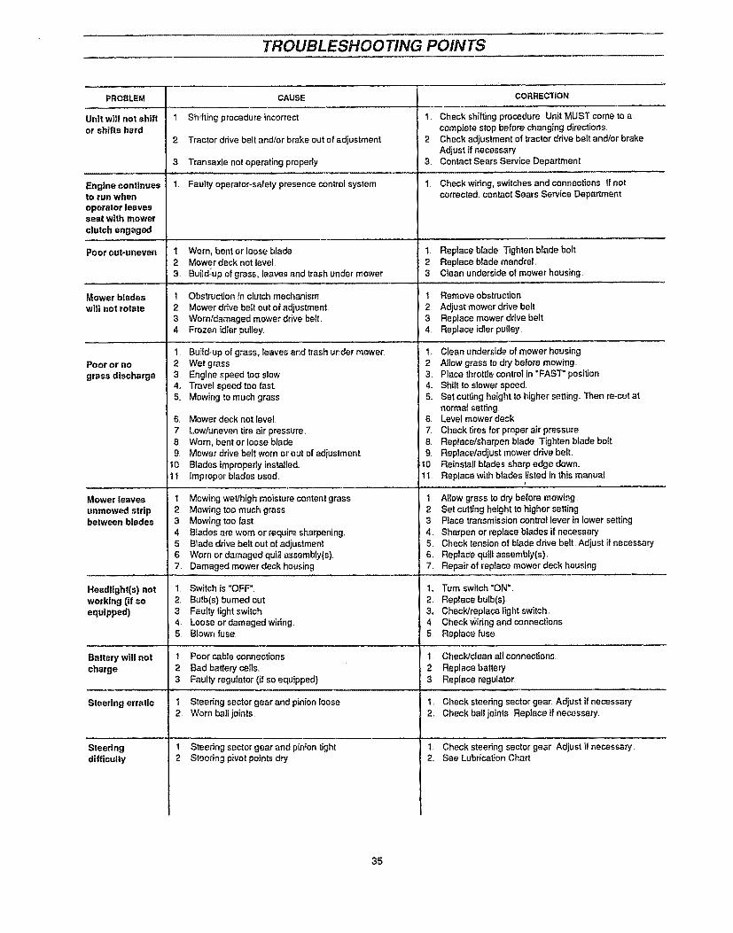
TROUBLESHOOTING POINTS
PROBLEM
Unit will not shiftor shifts hard
Engine continuesto run whenoperator leavesseal with mowerclutch engaged
Poorcut-uneven
Mower bladeswill not rotate
Poor or nograss discharge
Mower leaves
unmowed stripbetween blades
Headlight(s) notworking (if soequipped)
Batterywill notcharge
Steering erratic
Steeringdifficulty
CAUSE
1 Shifting procedure incorrect.
2 Tractor ddve belt and/or brake out of adjustment
3 Transaxle not operating properly.
1. Faulty operetor_safety presence control system
1 Worn, bent or loose blade2, Mower deck not level.3, Build;up of grass, leaves and trash under mower
1. Obstruction in clutch mechanism2 Mower drive belt out of adjustment3 Worn/damaged mower drive bell.4 Frozen idler pulley,
1
2 Wet grass3, Engine speed too slow4,, Travel speed too fast.5. Mowing to much grass
Build-up el grass, leaves and trash under mower
S.
7
89
10
11
Mower deck not level
Low/uneven tire air pressure..Worn, bent or loose bladeMower drive belt worn or out of adjustmentBlades improperly installed,Improper blades used.
1, Mowing wet/high moisture content grass2, Mowing too much grass3. Mowing too fast.4 Blades are worn or require sharpening,5 Blade drive belt out of adiustment6 Worn or damaged quifi assembly(s).7. Damaged mower deck housing
1 Switch is "OFF"2. Bulb(s) burned out,3 Faulty light switch4, Loose or damaged wiring,5. Blown fuse,
1 Poor cable connections
2 Bad battery cells,,3 Faulty regulator (if so equipped).
! Steering sector'gear and pinion loose2 Worn ball joints
1 Steering sector gear and pinion tight2 Steering pivot points dry
CORRECTION
1 Check shifting procedure Unit MUST come to acomplete stop before changing directions
2 Check adjustment of traclor drive belt and/or brakeAdjust if necessary
3. Contact Sears Service Department,
1. Checkwidng, switches and connections I! notcorrected, contact Sears Service Department
1 Replace blade Tighten blade bolt2, Replace blade mandrel,3, Clean underside of mower housing.
1 Remove obstruction
2. Adjust mower drive belt3 Replace mower drive belt4, Replace idler pulley
1. Clean underside of mower housing2 Allow grass to dry before mowing,3, Place throttle control in "FAST" position4.. Shift to slower speed5, Set cutting height to higher setting,, Then re-cut at
normal setting,6, Level mower deck7, Check tires for proper air pressure8, Replacetsharpen blade Tighten blade bol!9. Replace/adiust mower drive belt
!0 Reinstall blades sharp edge down,,t I Replace with blades fisled in this manual
1, Allow grass to dry before mowing,2 Set cutting height to higher setting,3 Place transmission control lever in lower setting
4 Sharpen or replace blades if necessary5 Check tension of blade drive belt Adjust if necessary6, Replace quill assembly(s),7 Repair of replace mower deck housing
1, Tum switch "ON"
2 Replace bulb(s)_3, ChecWreplace light switch,4 Check Wiring and connections5, Replace fuse,
1,. Check/dean all connections.
2. Replace battery3 Replace regulator.
1. Check steering sector gear Adjust if necessary2, Check ball joints Replace if necessary.
1 Check steering sector gear Adjust il necessary2 See Lubrication Chart
35

STORAGE.................... i i i
Immediately prepare your unit for storage at the end of theSeason or if the unit will not be used for 30 days or more..
DANGERNever store the engine with fuel indoors or in a poorlyventilated enclosure, where fuel fumes may reach anopen flame, spark or pilot light as on a furnace, waterheater, clothes dryer, etc.
Handle the gasoline carefully. It is highly flammable andcareless use could result in serious fire damage to yourperson and/or property.
Drain the fuel into an approved container outdoors awayfrom an open flame.
TRACTOR
Remove mower deck from tractor for winter storage Whenmower deck is to be stored for a period of time, clean it thor-oughly, remove all dirt, grease, ieaves, etc Give blades andunderside of mower deck housing a good coat of grease orrust preventative Store in a clean, dry area
e Clean entire tractor (See CLEANING in CUSTOMERRESPONSIBILITIES section of this manual).
® Inspect and replace belts, if necessary (See beltreplacement instructions in the SERVICE ANDADJUSTMENTS section of this manuat).
• Lubricate (see CUSTOMER RESPONSIBILITIESsection of this manual).
e Be sure all nuts, botts and screws are securely fastened.Inspect moving parts for damage, breakage and wear..Reprace if necessary,.
e Touch up all rusted or chipped paint surface; sandlightly before painting_
BATTERY
o
o
Fufly charge battery for storage..
After a period of time in storage, battery may requirerecharging,
e To hetp prevent corrosion and power teakage a'uringlong periods of storage, battery cables should bedisconnected and battery cleaned thoroughly (see TOCLEAN BATTERY AND TERMINALS in CUSTOMERRESPONSIBILITIES section of this manual)._
• After cleaning, leave cabEes disconnected and ptacecables where they cannot come in contact with batteryterminals.
ENGINEFUEL SYSTEM
IMPORTANT: IT IS IMPORTANT TO PREVENT GUMDEPOSITS FROM FORMING IN ESSEN-TIAL FUEL SYSTEM PARTS SUCH ASTHE CARBURETOR, FUEL FILTER, FUELHOSE, OR TANK DUR,ING STORAGE.ALSO , EXPERIENCE INDICATES THATALCOHOL-BLENDED FUELS (CALLEDGASOHOL OR USING ETHANOL ORMETHANOL) CAN ATTRACT MOISTUREWHICH LEADS TO SEPARATION ANDFORMATION OF ACIDS DURING STOR-AGE. ACIDIC GAS CAN DAMAGE THEFUEL SYSTEM OF AN ENGINE WHILE INSTORAGE.
• Drain fuel ta_ko
• Start engine and let it run until the fuel lines andcarburetor are empty
• Never use engine or carburetor cleaner products in fueltank or permanent damage may occur,
e Use fresh fuel next season.
NOTE: Fuel stabilizer (such as STA-BIL) is an acceptablealternative in minimizing formation of fuel gum deposits duringstorage. Add stabilizer to gasoline in fuel tank or storagecontainer Alwaysfol_ow mix ratiofound in stabilizer container..Run engine as least 10 minutes after adding stabilizer to allowstabilizer to reach the carburetor. Do not drain gas tank andcarburetor if using stabitizer:
ENGINE OIL.
Drain oil ('with engine Warm) and replace with clean engine oil.(See ENGINE IN CUSTOMER RESPONSIBILITIES sectionof this manual).
CYLINDERS
• Remove spark plugs._
• Pour one ounce of oil through spark plug holes intocylinders_
• Turn ignitionkey to START position for a few secondstodistribute oil
• Replace with new spark plugs,.
OTHER
• Do not store gasoline from one season to another.
• Replace your gasotine can if your can starts to rusLRust and/or dirt in your gasoline witl cause problems..
• If possible, store your tractor indoors and cover it to giveprotection from dust and dirt.
o Cover tractor with a suitabte protective cover that doesnot retain moisture, Do not use plastic,, Plastic cannotbreathe which allows condensation to form and willcause your tractor to rust.
IMPORTANT: NEVER COVER TRACTOR WHILEENGINE AND EXHAUST AREAS ARESTILL WARM.
36

NOTES
37

CRAFTSMAN 43" LAWN TRACTOR MODEL 536.255870
CHASSIS & HOOD ASSEMBLY
REEKEY#44
REF,MOWERSUSP,! PG
HOODPIVOT
NOTE: ALWAYS USE ORIGINALEQUIPMENT PARTS,. Use of serv-ice/replacement parts other thanoriginal equipment parts may voidyour warranty
REF,
STEERING PG,FRONT AXLE ASSY
ALL UNNUMBEREDITEMS ARE INTERCHANGEABLE
WITH OPPOSITE SIDE 328O43A
38

CRAFTSMAN 43" LAWN TRACTOR MODEL 536.255870
key# part# description
I 326580-8292 3147993 3100064 3092355 323068-8536 313541-8537 560308 552739 30044010 .14981t 30820712 30900813 "12220714 248315 "149916 30063517 .12482418 "27119019 315120°82920 467632I 3549722 99534623 324111-83024 99534625 99533826 5035227 31971828 32181028A 32449128B 32449229 31813930 5456931 ,150232 31830433 32813334 32813135 32813236 31604337 31688138 t50139 31496740 3149684I 32304442 99642543 826044 32804245 31604246 301452
327865
FRAME,LF MAIN P920/F4360 SEARSFOOTPAD,LH PEDAL LIFTFOOTPAD,RHFASTENER, RATCHETBRACKET, GRILLEBRACKET, FRONT AXLESCREW, 5/16-18X,75WDFLLKNUT, 5!16-t8 HXWDFLLKGUIDE, BELT, RIDERNUT, 5/t6-18 REGHEXCTRLKBOLT, 625X2 18 HHSH 112-13NUT, 1t2-13 HEXJAM CTRLKSCREW, 3/8-16X3 00 HHCWASHER, 391DXI .25DX,,07 BELLVtLNUT, 318-16 REGHXCTRLKGUIDE,BELT SHORT 15" WHEELNUT. 5/16-18 HEXJAMNUT, 3/8-16 HEXKEPSCONSOLE, PEDAL LIFTRIVET. POP ,,187DIAX 450LG STSCREW, 5/!8-t8X .50 WAHHTAPSCREW, t/4-20X 50 WAHHTAPDASH, STEELSCREW, 1/4-20X 50 WAHHTAPSCREW, I/4-20X 63 HHWATAPNUT, 114-20 WDFLLK TOPLOCKDASHBUMPER TOPBUMPER-HOOD/DASH SIDE TOPBUMPER-HOOD/DASH SIDE BOTTOMSCREW, 114-20 PHPNHDWASHER, FLAT 28tX .75X 090NUT, 1/4-20 REGHXCTRLKSCREW, tI4-20X 50 PHPNTAPHOODSKIRT, HOODGRILLESCR #10X1 0 UNSL-HWH-HILO ZINCSCR #t0X.75 UNSL-HWH-HILO ZINCFLATWASHER #10LENS LH, SEARSLENS RH, SEARS
PIN, CLEVISFLATWASHERPIN, HAIRLANYARD,HOOD 18.00 LG LFSCR #10X 62 UNSL-HWH-HILO ZINCFOIL, HEAT REFLECTOROWNER'S MANUAL (NOT ILLUSTRATED)
" STANDARD HARDWARE ITEMS.
qty,
1111221551t11222111132912441242242211I8614tI22141121
39!

CRAFTSMAN43" LAWN TRACTOR MODEL536.255870
HOOD AND CHASSIS ASSEMBLY
REF _)MOTION DRIVEPAGE ",..
KEY#23
!
\
\
o
REFKEY#t
NOTE: ALWAYS USE ORIGINALEQUIPMENT PARTS, Use of serv-ice/replacement parts other thanoriginal equipment parts may voidyour warranty.
ALL UNNUMBEREDITEMS ARE INTERCHANGEABLE
WITH OPPOSITE SIDE 328043A
4O

CRAFTSMAN 43" LAWN TRACTOR MODEL 536.255870
key# part# description
64 58367-853
65 310660-853
66 20507
67 ,I498
68 48901
69 .1498
70 57_53
71 1341
72 44811
73 569O7
74 308654-829
75 995346
76 *122017
77 446363
78 "1498
79 55021
80 327061-829
8I 48146
82 180079
83 120393
84 1498
85 321863
86 12200787 120638
88 120393
PLATE, SEATBRACKET, P-5 SEAT SUPPORTBOLT, 437X t56 HHSH 5/t6-18NUT, 5/16-18 REGHEXCTRLKSCREW, 5116-18X 63 HHCNUT, 5/16-18 REGHEXCTRLKSPRING,SEAT 2 63LG1 49ODCLAMP,SPRING 1 t7"IDSCREW, 114-20X ,75 HXWATAPCOVER,SEAT SPRING 1 51DX1 0LGFENDERSCREW. !/4-20X ,50 WAHHTAPSCREW, 5/I6-t8X1,00 HHCWASHER. FLAT .375X .88X 082NUT. 5116-18 REGHEXCTRLKTRIM,STRIP,BLACK--SMALL.W/ADHHITCH. SEARSSCR, 3/8-16 X t 000 HXWAHD TAPSCR 5/t6q8 X 63 HHCWASHER FLAT 344 X .69 X 065NUT, 5/16-18 REGHEXCTRLKSEAT. MV540 CRAFTSMANSCREW, 5/16q8 X ,75 HHCWASHER. HVSPTLK 328 X .60 X 09WASHER. FLAT 344 X 69 X 065
" STANDARD HARDWARE ITEMS°
qty
11224422221424275"t22221444
4I
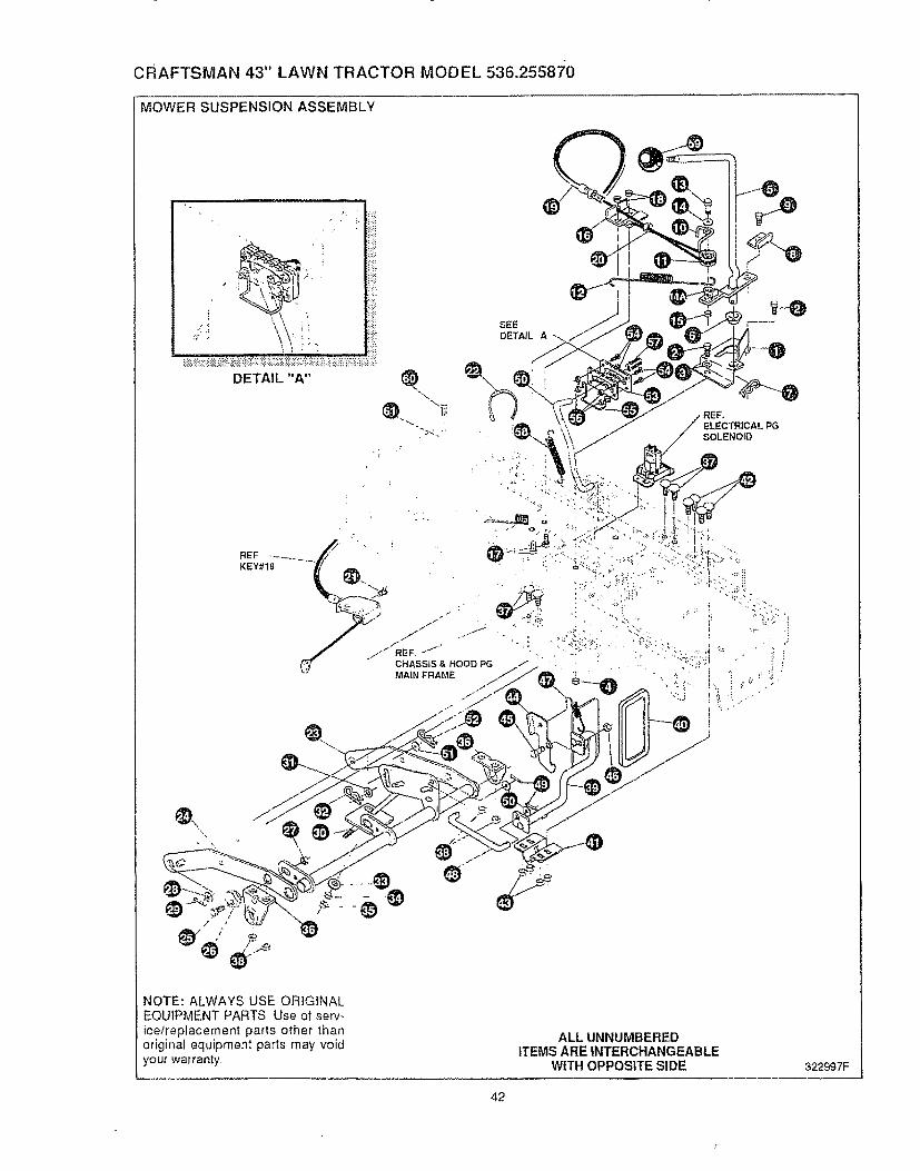
CRAFTSMAN 43" LAWN TRACTOR MODEL 536.2558"/0
MOWER SUSPENSION ASSEMBLY
NOTE: ALWAYS USE ORIGINALEQUIPMENT PARTS, Use of serv-ice/replacement parts other thanoriginal equipment parts may voidyour warranty
ALL UNNUMBEREDITEMS ARE INTERCHANGEABLE
WITH OPPOSITE SIDE
42
322997F
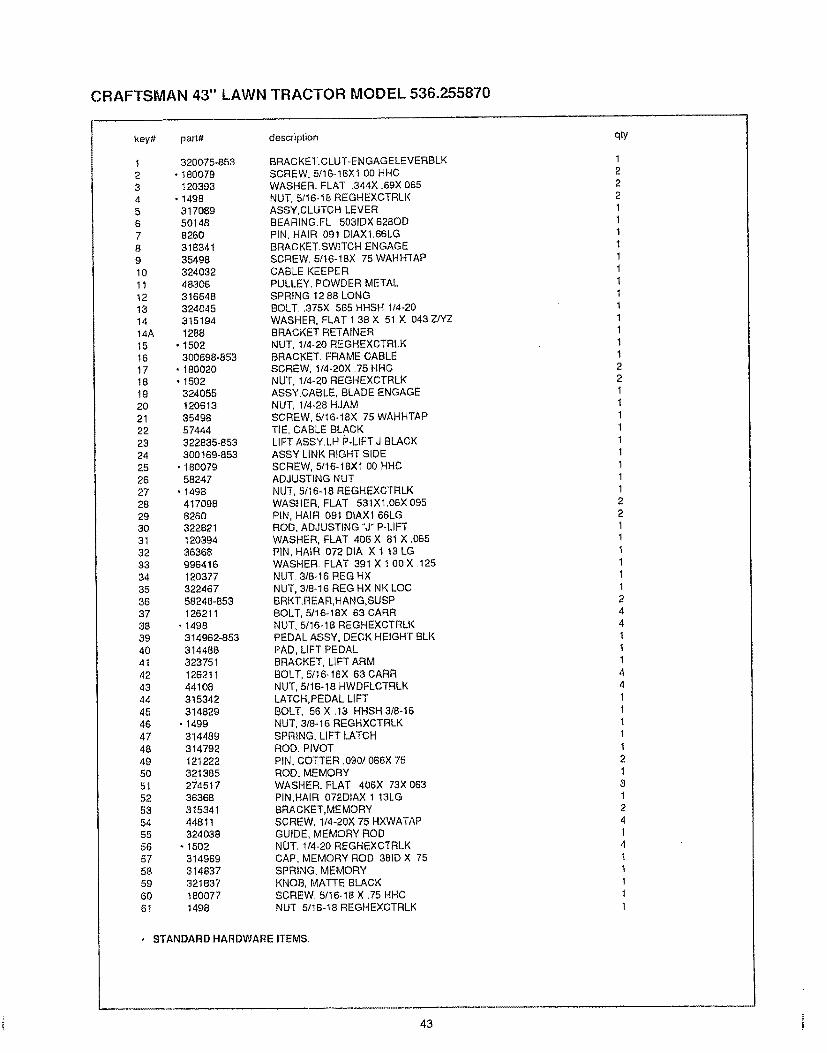
CRAFTSMAN 43" LAWN TRACTOR MODEL 536.255870
key'# part# description
1 320075-8532 .1800793 1203934 .14985 3170896 501487 82608 3183419 3549810 3240321! 48306t2 31664813 32404514 31519414A 1288t5 .t502t6 300698-85317 . 18002018 °1502!9 32405520 12061321 3549822 5744423 322835-85324 300169-85325 .18007926 5824727 "149828 41709829 826030 3228213l 12O39432 3636833 99641634 12037735 32246736 58248-85337 12621138 "t49839 314962_85340 31448841 32375142 12621143 4410844 31534245 31482946 .t49947 31448948 31479249 12122250 32138551 27451752 3636853 31534154 4481155 32403856 -150257 31496958 31483759 32183760 18007761 t498
BRACKET.CLUT-ENGAGELEVERBLKSCREW, 5/16-!8X! O0 HHCWASHER- FLAT .344X .69X 065NUT, 5f16-18 REGHEXCTRLKASSY,CLUTCH LEVERBEARING.FL 5031DX 628ODPIN, HAIR 09t D1AXl.56LGBRACKET.SWITCH ENGAGESCREW. 51t6-18X 75 WAHHTAPCABLE KEEPERPULLEY. POWDER METALSPRING 1288 LONGBOLT..375X 565 HHSH 1/4-20WASHER, FLAT 1 38 X 51 X 043 Z/YZBRACKET RETAINERNUT, 1/4-20 REGHEXCTRLKBRACKET. FRAME CABLESCREW, t/4-20X 75 HHCNUT, 1/4-20 REGHEXCTRLKASSY.CABLE, BLADE ENGAGENUT, 1/4-28 HJAMSCREW, 5/16-18X 75 WAHHTAPTIE, CABLE BLACKLIFT ASSY.LH P-LIFT J BLACKASSY LINK RIGHT SIDESCREW, 5/16-18X1 00 HHCADJUSTING NUTNUT, 5116-18 REGHEXCTRLKWASHER, FLAT 531Xl.06X 095PIN, HAIR 091 DIAXI 66LGROD, ADJUSTING "'J" P-LIFTWASHER, FLAT 406 X 81 X .065PIN, HAIR 072 DtA X t t3 LGWASHER FLAT 391 X t 00X I25NUT. 3t8-t6 REG HXNUT, 3t8-16 REG HX NK LOCBRKT,REAR,HANG_SUSPBOLT, 5t16-18X 63 CARRNUT. 5/16-18 REGHEXCTRLKPEDAL ASSY, DECK HEIGHT BLKPAD, LiFT PEDALBRACKET, LIFT ARMBOLT, 5116-18X 63 CARRNUT, 5!16-t8 HWDFLCTRLKLATCH,PEDAL LIFTBOLT, 56 X .t3 HHSH 3t8-t6NUT, 318q 6 REGHXCTRLKSPRING. LIFT LATCHROD, PIVOTPiN, COTTER .090! 086X 75ROD, MEMORYWASHER. FLAT 406X 73X 063PIN,HAIR 072DIAX ! 13LGBRACKET,ME MORYSCREW, 1/4-20X 75 HXWATAPGUIDE, MEMORY RODNOT. 114-20 REGHEXCTRLKCAP, MEMORY ROD 381D X 75SPRING. MEMORYKNOB, MATTE BLACKSCREW. 5f16-t8 X .75 HHCNUT. 51t6-18 REGHEXCTRLK
. STANDARD HARDWARE ITEMS,
qty
1222111t1111111t1221111lI111221!11t124411144I1111213t241411111
!43 !
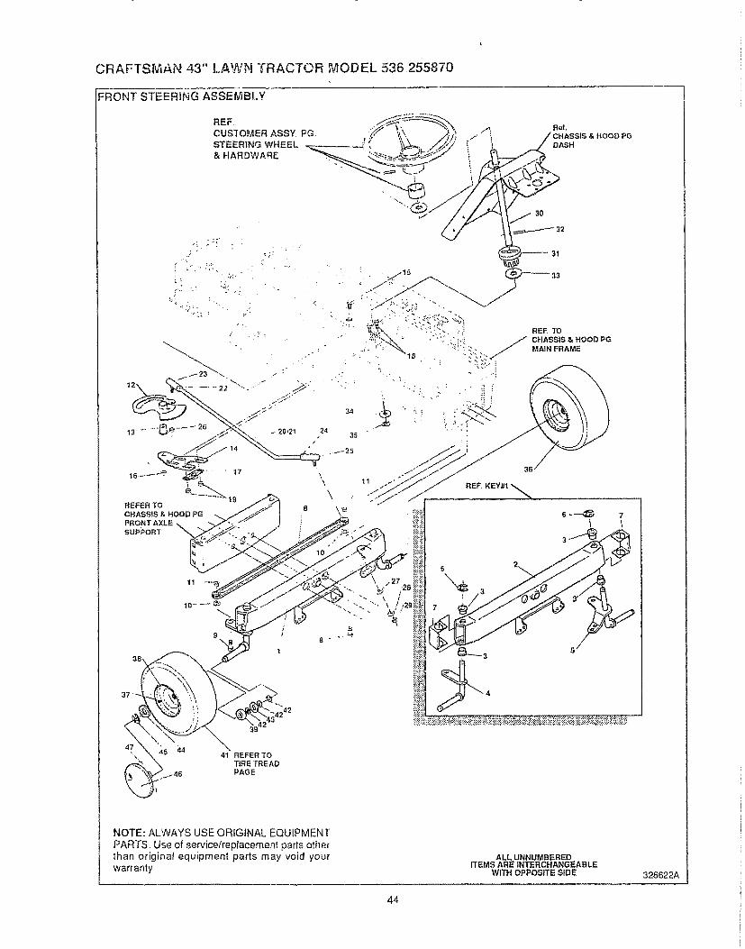
CRAFTS_IAN 43" LAWN TRACTOR _2,ODEL 536.255870
FRONT STEERING ASSEMBLY
REF,CUSTOMER ASSY FGSTEERING WHEEL& HARDWARE
14
t6 .......... _ ' 17
1
19REFER TO
CHASSIS & HOOD PGFRONT AXLE
SUPPORT
REF, TO
CHASSIS & HOOD PGMAIN FRAME
& HOOD PG
,t242
39
'\\
41 REFER TOTIRE TREADPAGE
NOTE: ALWAYS USE ORIGINAL EQUIPMENTPARTS. Use of service/replacement parts otherthan original equipment parts may void yourwarranty
ALL UNNUMBEREDITEMS ARE INTERCHANGEABLE
WITH OPPOSITE SIDE 328622A
44

CRAFTSMAN 43" LAWN TRACTOR MODEL 536.255870
key# part# description
1
2 300272-853
3 524074 318539
5 318544
6 36625
7 53373-853
8 304590
9 • 180128
t0 - 120382
11 . 120377
t2 313634
t3 313629
14 313671-853
t5 315196
16 27465417 302498
18 323731
t9 71100
20 323752
21 321449
22 124925
23 5715824 272123
25 302865
26 46692
27 120396
28 120383
29 271506
30 318702
3I 302314
32 302524
33 315194
34 2968
35 20864
3637 24{67
38 321908
39 314416
40 706
41 316702
42 73840
43 318550
44 64245 36625
46 306571
47 306669
AXLE.FRONT ASSY SUS 4WS LFASSY,FRONT AXLE SUSSPINDLE BEARINGASSY.SPfNDLE RH LONGASSY,SP1NDLE,LH LONGRING, RETEX 57X 05TRU5133-75AXLE COVERTIE ROD ASSY 19 81LG W-SECTIONSCREW, 3/8-16X1 75 HHCWASHER, REGSPTLK 393X 68X 10NUT, 3/8q6 REGHEXASSY SECTOR GEAR 4WS LFBUSHING,SECTOR GEAR 4WS LFSUPPORT,SECTOR GEAR 4WS LFSCREW, t/2-20X3.00 HHCNUT, 1/2_20 REGHXCTRLKBEARING FLANGE 0.5 BORESCREW, 5f16_24 X.75 SQ CONE SEMSNUT, 5/16_24 HXWDFLLKASM DRAGLINK 4WS LFDRAG LINK 625 DIA LF 4WSNUT, 3/8-24 REGHEXJAMBALL JOINT 3/8 THD SHORT STUDNUT, 7/t6_20 HXJAMJOINT, BALL ASSY 71t6-20NUT, 3!6-24 WDFLHLK WHIZWASHER. FLAT ,531X1.06X 095WASHER, REGSPTLK 459X 78X 12NUT, 7/t6o20 REGHXSHAFT, STEERING 4WS LFPINION STEERINGPIN DOWEL STR ERO LTWASHER,FLAT 1.38 X 5tX 043WASHER, FLAT .504X.75X 059RING. RET E .39X.04TRU5133_50TiRE & RIM. PU 15X6 0X6 TURF SILVER 654VALVE STEMWH EEL W/BRGBEARINGZERK FITTINGREFER TO TIRE TREAD PAGEWASHERWASHER. FELTWASHER, FLAT 755 X 13I X ..075RING, RETEX 57X.05TRU5133-75HUBCAP 6 _SILVER 3251854CLIP
qlyo
II4!122122211111122111It!!tttt1t1t121112
622228
" ORDER INDIVIDUAL PARTS.. STANDARD HARDWARE ITEMS°
45

CRAFTSMAN 43" LAWN TRACTOR MODEL 536.255870
REAR STEERING ASSEMBLY
/
_ ,', i_ '_
!9 20
REFCHASSIS & HOOD PG
_, _: .// MAINFRAME
NOTE: ALWAYS USE ORIGINAL EQUIPMENTPARTS, Use of service/replacement parts otherthan original equipment parts may void yourwarranty
ALLUNNUMBEREDITEMS AREINTERCHANGEABLE
WRH OPPOSITESIDE326t37A
46

CRAFTSMAN 43" LAWN TRACTOR MODEL 536.255870
key# part# description
I 303222-8532 1800913 1203934 14985 354986 3261357 3142678 124659 1232510 32053111 12280-83012 3631113 12289t4 324578!5 2168216 32457817 45672218 12201719 12039320 149821 32451422 30871923 1231924 12039425 30411526 2517727 4560228 42105129 30259430 30411631 30412232 27465433 32463834 9963O735 41234936 30872037 32363438 30844739 30839940 3083844t 12492542 30426043 32363544 3O844645 30839946 30838447 12492548 3O426049 18164650 4123495! 304t20_85352 304!21_85353 3972854 18163985 12038256 452349
BRKT X-AXLE MTG0SCREW, 5tI6_18X2 50 HHC
WASHER, FLAT .344X .69X 0650NUT, 5/16q8 REGHEXCTRLK0SCREW, 5/16_18X .75 WAHHTAP
U-JOINT ASM 4WS LD LFBRCKT,STRG PIVOT W/DRILL HOLESBRACKET.STR PIVOTBEARINGU_JOINT ASSEMBLY (LONG)HUB ASSEMBLY GREY 86tPIN. GROOVED .250 DIAX1 50LGPiN, STEERING HINGEBUSHING. SHOULDERED (OILITEWASHER, FLAT .765Xt.25X.042 PLBUSHING, SHOULDERED (OILITEPIN, SPRING 250DIAX1 50LG HVPL
0SCREW, 5/16-t8X1 00 HHCWASHER, FLA'r .344X .69X 065
0 NUT. 5It6-18 REGHEXCTRLKROD ASM., DRAGLINKPIVOT. STEERINGBOLT_ .562X 340 HHSH 318-24WASHER. FLAT 406X 81X.065SPACER, STEERING SHAFTWASHER. FLAT 765X1 19X 048WASHER, FLAT 333X 87X t19
0SCREW, 5/I6-24X1 00 HHCARM ROLLER SWING 4 WCAM YOKE ROLLERSHOULDER BOLT CAM ROLLER
0 NUT. 1/2_20 REGHXCTRLKSHOULD BOLT CAM FOLLOWERWASHER, FLAT .391Xl L)0X 209
ONUT, 3/8-24 HXCTRLKSHAFT, STEERING PIVOTTIE ROD ASSY RHROD. TIE t/2"D X 8.00LG
0NUT, 3/8-24 LH THD REGHJAMROD,TIE END LH 3t8-24 EURO
0 NUT, 3/8o24 REGHEXJAMROD, TIE END RHTIE ROD ASSY LHROD. TIE 112_DX 9.5LGNUT, 3,'8-24 LH THD REGHJAMROD.TIE END LH 3/8-24 EURONUT. 3/8-24 REGHEXJAMROD, TIE END RH
0SCREW, 318_24Xt.75 HHC0 NUT, 3t8-24 HXCTRLK
ARM RW STR ERO RHARM RW STR ERO LH
_)SCREW. 3t8-t6X 75WAHHTAP BK0SCREW, 3/8-24Xl,25 HHC
WASHER, REGSPTLK 393X 68X 100 NUT, 3/8-24 HXCTRLK
qty
2444422242224222481681tttt2111t1111111111111ttI1ttttt4222
Indicates STANDARD HARDWARE ITEMS
47
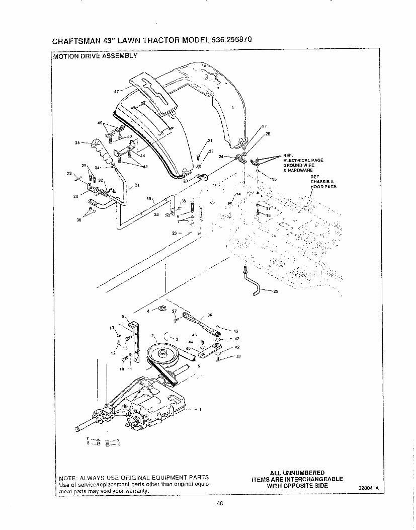
CRAFTSMAN 43" LAWN TRACTOR MODEL 536,.255870
MOTION DRIVE ASSEMBLY
49
33
NOTE: ALWAYS USE ORIGINAL EQUIPMENT PARTSUse of service/replacement parts other than original equip-ment parts may void your warranty,
48
ALL UNNUMBEREDITEMS ARE INTERCHANGEABLE
WITH OPPOSITE SIDE 328041A
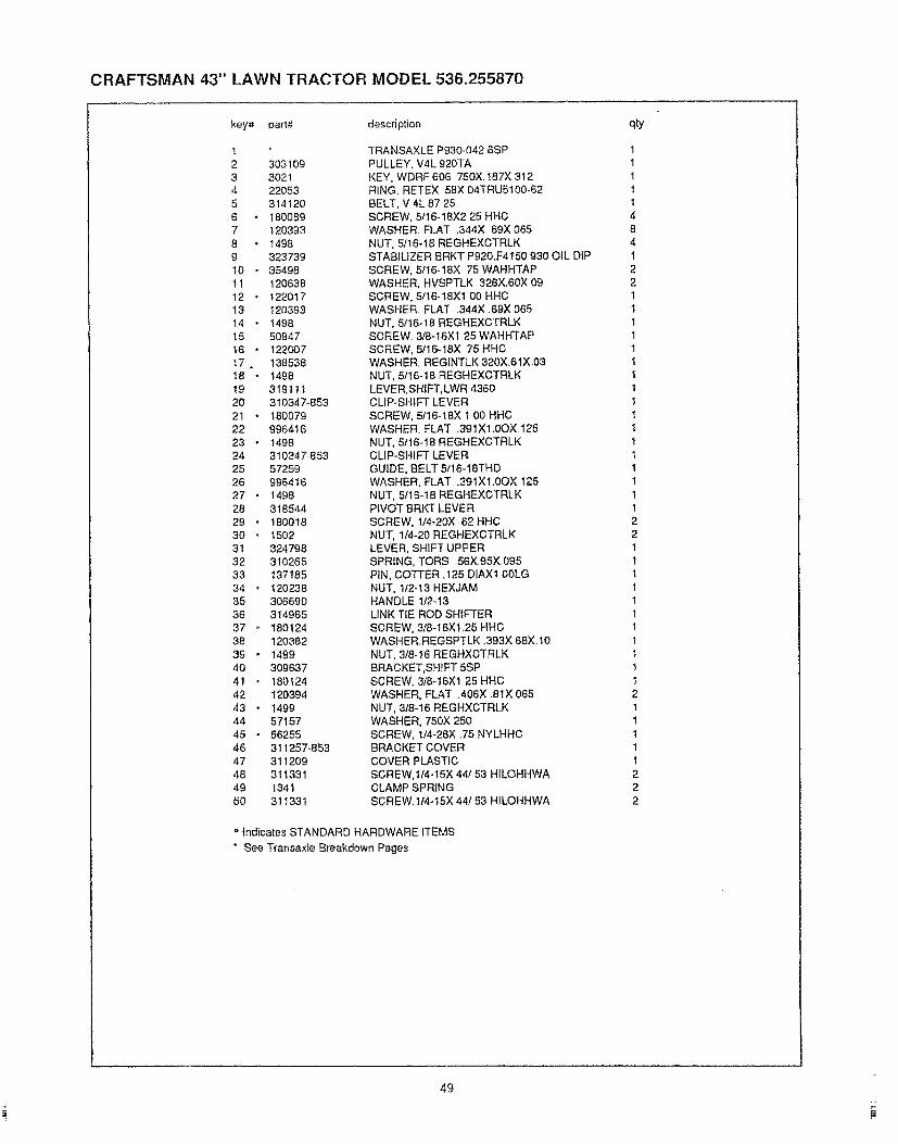
CRAFTSMAN 43" LAWN TRACTOR MODEL 536.255870
key# part# description
!2 3031093 3o214 220535 3141206 1800897 1203938 • 14989 323739t0 • 35498tl 120638I2 • 122017t3 12039314 , 149815 50947t6 • 122007t7. 138538I8 " t49819 31911120 310347-85321 • 18007922 99641623 " I49824 310347-85325 5725926 99641627 • 149828 31854429 * 18001830 " t5023I 32479832 31026533 13718534 • 12023835 30669036 31496537 " 18012438 12038239 • 14994O 3096374t 18012442 12039443 • t49944 5715745 • 5625546 311257-85347 31120948 31133149 134I5O 311331
TRANSAXLE P930-042 6SPPULLEY, V4L 920TAKEY, WDRF 606 750X t87X 3t2RING, RETEX 58X 04TRU5100-62BELT, V 4L 87 25SCREW, 5t16-18X2 25 HHCWASHER, FLAT .344X 69X 065NUT, 5/16-!8 REGHEXCTRLKSTABILIZER BRKT Pg20.F4150 930 OIL DiPSCREW, 5/t6-18X 75 WAHHTAPWASHER, HVSPTLK 328X.60X 09SCREW, 5,"16-18X1 O0 HHCWASHER FLAT .344X 69X 065NUT, 5t 16-18 REGHEXCTRLKSCREW_ 318q6X1 25 WAHHTAPSCREW, 5,,'16-18X _75 HHCWASHER, REGINTLK 320X.61X 03NUT, 5/t6-18 REGHEXCTRLKLEVER,SHIFT,LWR 4360CUP-SHIFT LEVERSCREW, 5/16o18X t 00 HHCWASHER. FLAT .39tX1.0OX 125NUT, 51t6-18 REGHEXCTRLKCLIP-SHIFT LEVERGUIDE, BELT 5!16-ISTHDWASHER, FLAT .391X1.0OX t25NUT, 5116°18 REGHEXCTRLKPIVOT BRKT LEVERSCREW, 1/4-20X 62 HHCNUT, 1/4-20 REGHEXCTRLKLEVER, SHIFT UPPERSPRING, TORS 56X 95X 095PIN, COTTER .125 DIAXt 00LGNUT, t/2-13 HEXJAMHANDLE 1t2-13LINK TIE ROD SHIFTERSCREW, 3/8-16Xt.25 HHCWASHER,REGSPTLK .393X 68Xt0NUT, 3t8-t6 REGHXCTRLKBRACKET,SHIFT 5SPSCREW. 3/8q6X1 25 HHCWASHER, FLAT ,406X .8t X 065NUT, 3/8q 6 REGHXCTRLKWASHER, 750X 250SCREW, t/4-28X .75 NYLHHCBRACKET COVERCOVER PLASTICSCREW,tI4-15X 44! 53 H1LOHHWACLAMP SPRINGSCREW,1t4-!5X 44/53 HILOHHWA
= Indicates STANDARD HARDWARE tTEMS
" See Transaxle Breakdown Pages
qty
11It!48412211111t11tt!tII11122111111t1tIt2t1t1!222
49

CRAFTSMA_ : 43 '' LAWN TRACTOR MODEL 536.255870
MOTION DRIVE ASSEMBLY
REF "_ '= '; ; '
CHASSIS & HOOD PG *. !
MAIN FRAME ";_ _
91• 89 REF,
TiRE TREAD PG
NOTE: ALWAYS USE ORIGINAL EQUIPMENT PARTSUse o;_service!replacement parts other than original equip-nlen! parts may' void your Warranty. .............
50
ALL UNNUMBEREDITEMS ARE INTERCHANGEABLE
WITH OPPOSITE SIDE 328041A
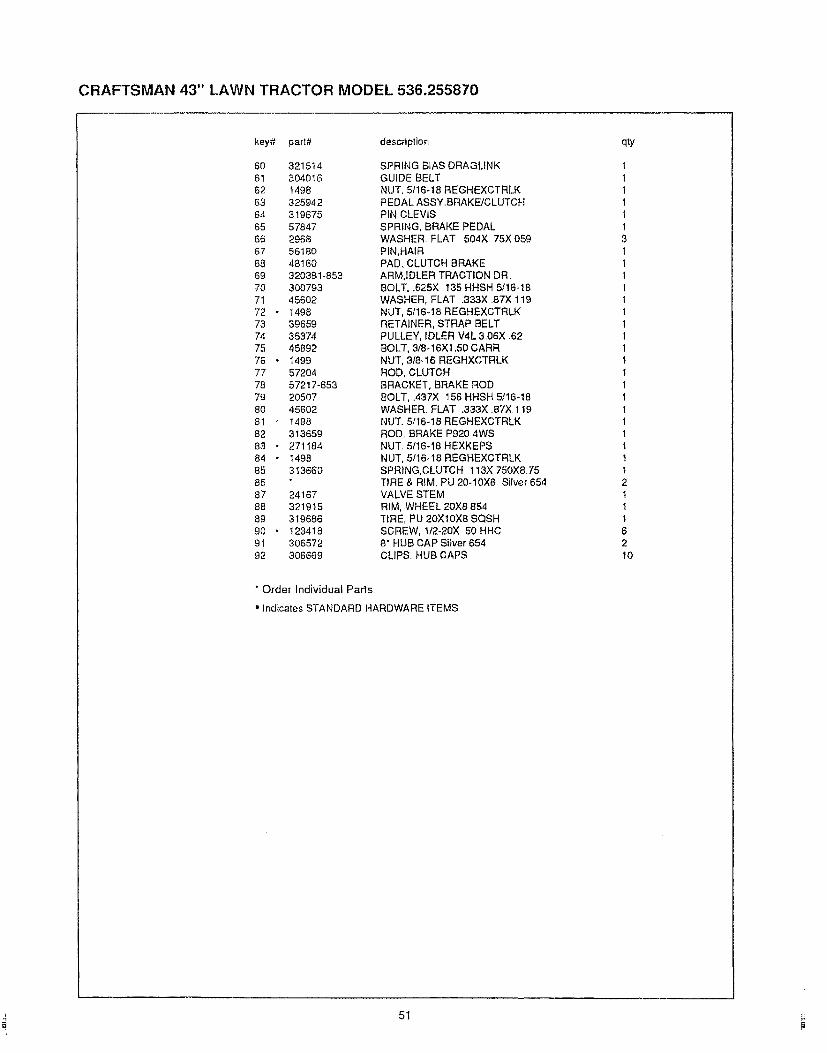
CRAFTSMAN 43" t.AWN TRACTOR MODEL 536,255870
key# part# description
60 321514
61 304016
62 1498
63 325942
64 319675
65 57847
66 2968
67 56180
68 48160
69 320381-853
70 300793
71 456O2
72 - 1498
73 39659
74 35374
75 45892
76 - t499
77 57204
78 572t7-853
79 20507
80 45602
81 1498
82 31365983 • 271184
84 • 1498
85 313660
86
87 24167
88 321915
89 319686
90 , 123418
91 306572
92 306669
SPRING BIAS DRAGUNKGUIDE BELTNUT. 5116-18 REGHEXCTRLKPEDAL ASSY.BRAKE/CLUTCHPIN CLEVISSPRING, BRAKE PEDAL'WASHER. FLAT 504X 75X 059PIN,HAtRPAD, CLUTCH BRAKEARM,IDLER TRACTION DRBOLT, .625X t35 HHSH 5116-t8'WASHER, FLAT .333X .87X 119NUT, 5!t6-t8 REGHEXCTRLKRETAINER, STRAP BELTPULLEY, IDLER V4L 3.06X 62BOLT, 3/8-t6XI .50 CARRNUT, 3/8q6 REGHXCTRLKROD, CLUTCHBRACKET, BRAKE ROD8OLT, .437X 155 HHSH 5/16q8WASHER. FLAT .333X .87X. 119NUT. 5/t6-18 REGHEXCTRLKROD. BRAKE P920 4WSNUT. 5/t6-18 HEXKEPSNUT, 5/16-t8 REGHEXCTRLKSPRING,CLUTCH 113X 750X8 75TIRE & RIM, PU 20-10X8 Silver 654VALVE STEMRIM, WHEEL 20X8 854TIRE, PU 20XtOX8 SQSHSCREW, !12-20X 50 HHC8" HUB CAP Silver 654CLIPS. RUB CAPS
' Order Individual Parts
• Indicates STANDARD HARDWARE 1TEMS
qty
!tt!tt3ttt1!Itt11111111111211162lO
51 _:
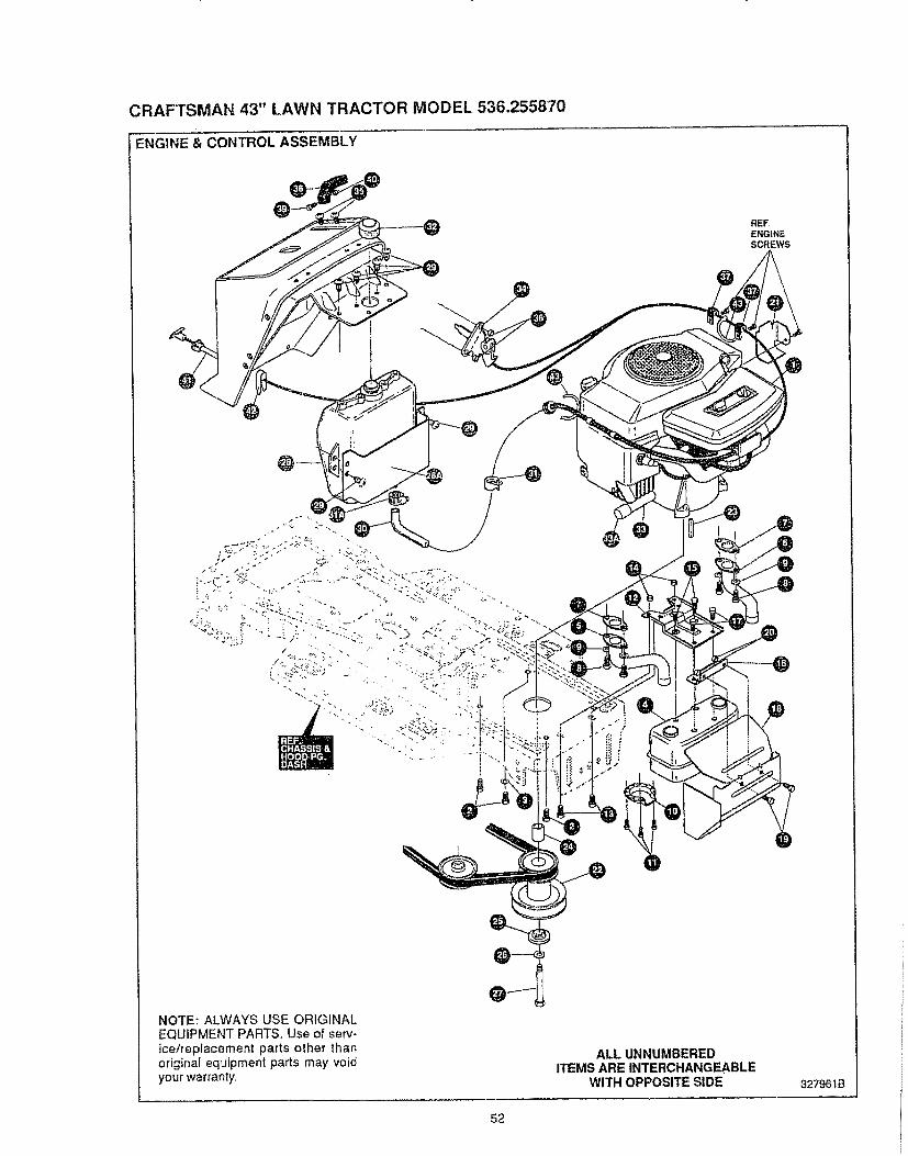
CRAFTSMAN 43" LAWN TRACTOR MODEL 536.255870
ENGINE & CONTROL ASSEMBLY
NOTE: ALWAYS USE ORIGINALEQUIPMENT PARTS, Use of serv-ice/replacement parts other thanoriginat equipment parts may voidyour warranty,
52
ALL UNNUMBEREDITEMS ARE INTERCHANGEABLE
WITH OPPOSITE SIDE 327961B

CRAFTSMAN 43" LAWN TRACTOR MODEL 536.255870
KEY# PART# DESCRIPTION
1 *
2 509473 1384894 3055505 3055526 3055517 566408 t800209 12038010 5647211 3528712 304709-85313 5603014 5527315 99534616 9796t7 99533818 327938-65319 18007720 5527321 56470-85322 32803423 30315124 30424625 5643126 12038327 43314628. 31499228A 301087-85329 4905030 4100731 4734531A 4734532 4670433 32554733A. 4782834 30909235 32055336. 27116637 5756938 30050839 15958540 12062238 5653839 3525640 506074t 32798642 31452243 57444
" See Engine Pages.
ENGINE,B&S 15HP TWIN OPP!tCSCREW, 318-16X1.25 WAHHTAPBLKPWASHER, EXLK 384X,69X 04MUFFLER,16118HP LARGE LC-TONEEXHAUST TUBE RHEXHAUST TUBE LHGASKET, MUFFLERSCREW, 114-20X .75 HHCWASHER, REGSPTLK.263X 49X.07DEFLECTOR S] DE OUT (BS222573)SCREW, #8-32X .38 HHWATAPBRACKET, MUFFLERSCREW, 5I! 6-18X.75WDFLLKNUT, 5/16-18 HXWDFLLKSCREW, 1/4-20X .50 WAHHTAPBRACKET, TRANSAXLE MOUNTINGSCREW, 114-20X .63 HHWATAPSHIELD,MUFFLER HEATSCREW, 5116-18X .75 HHCNUT, 5/I 6-18 HXWDFLLKDEFLECTOR, COOL AIRPULLEY. ENG V3L 4 00 OFFSETKEY, SQUARE .249SQX4 50LGSPACER, SLEVt..01X1,484X ,WASHER, 980IDX1.38ODX.437P_LOTWASHER, REGSPTLK 459X78X 12SCREW, 7116-20X4 25 HHC BLK PHTANK. FUEL 2 GAL CLEARSHIELD, HEAT FUEL TANKSCREW, 1/4-10X .75PHPNTAPTUBING,. 25XSOX BULK GAS LINECLAMP HOSE, SCREW TYPECLAMP, FUEL LINE REDCAP, GAS 1-1/2-7 THD BLKOIL DRAINCAP, PIPE 3/89_18 NPTCONTROL, THROTTLESCREW, 10-24X.63PHPNMA CRSSNUT, #10-24 HEXKEPSWIRE RETAINERKNOB, THROTTLESCREW #8-32 X .38 PHPNMANUT, #8-32 REHEXRETAINER, WIRESCREW, I0-24X.38 SLHWATAPKNOB, ROUND THROTTLE BLACKCONTROL CHOKE 4225LG PAN TKCLIP, CHOKE RETAINERTIE. CABLE BLACK
QTY
141111244131222I21221IIIIIItI6t5"t2IIt1222t11111112
53

CRAFTSMAN 43" LAWN TRACTOR MODEL 536.255870
PRE-PAINTED DECK ASSEMBLY
REF,KEY
NOTE: ALWAYS USE ORIGINAL EQUIPMENTPARTS Use of service/replacement parts other thanoriginal equipment parts may void your warranty.
ALL UNNUMBEREDITEMS ARE INTERCHANGEABLE
WITH OPPOSITE SIDE 327957C
54

CRAFTSMAN 43" LAWN TRACTOR MODEL 536.255870
KEY# PART# DESCRIPTION
1 3274522 326480-8533 1800754 14985 1220076 14966A 327280-85368 1220276C 14987 3170178 1800759 120393!0 I498_I 31392912 180077t 3 120393I4 t49815 31066716 18007717 12039318 t49819 326893-85319A 30823120 18007722 4410823 55424-85324 5642525 4956226 5061627 5554728 4956229 5081830 514493t 5639032 31389833 128234 5063435 30034536 149837 31377838 18007539 149840 5830541 5824742 12201743 149844 30442645 18007546 149847 32246448 31428249 180075SO t4985t 32576252 248353 4766554 32057655 32211656 4160157 30697358 30442059 99641660 99630761 4517162 32624963 t 8007564 t 8008365 44836366 27118467 149868 32182869 304i t9-85370 30697371 13562472 18007573 12039374 I49875 31407976 t50277 3541078 32757079 12621680 1498
MOWER DECKS. RIDER 43 _MULCHINGTOE GUARDSCREW. 5/16-18X 63 HHCNUT, 5/t 6-18 REGHEXCTRLKSCREW. 5/!6q8X 75 HHCNUT, 5/t6-18 REGHEXCTRLKBRACKET, REFLECTOR STOPSCREW, 5/16q 8X1.25NUT, 5/t6.18 REGHEXCTRLKBRACKET CHUTE MOUNTSCREW, 5/16.18X ,63 HHCWASHER,FLAT ,344x.6gx.065NUT. 5/16-18 REGHEXCTRLKLIFT BRACKET, REAR,RHSCREW, 5/t6-18X .75 HHCWASHER. FLAT .344X .6gx 065NUT, 5fl 6-t 8 REGHEXCTRLKBRACKET,DECK UFTREAR LHSCREW, 5!tTq8X .75 HHC GR5WASHER, FLAT .344X .89X865NUT, 5/I6-18 REGHEXCTRLKBRACE IDLERSCREW, 1/4-20Xl 25 HHWATAPSCREW, 5/1648X .75 HHCNUT, 5/16-18 HWDFLCTRLKQUILL ASSY, 36/39/40/43SHAFTISADDLE 36"BRNG, BALLDUST SHIELDQUILL CAST{NG (1046)BRNG. BALLSPACER,3.797LGX,6691DXB8ODSPACER,.438LGX 9320DX 672{DPULLEY.2_36" QUILL V5LSPECIAL WASHERNUT, 7/16.20 WDFLLKSCREW, 5/16-18X .88 WAHHTAPSCREW, 5/t6-18Xl 38 WATAPNUT, 5/16-t8 REGHEXCTRLKBRACKET FRT.SCREW, 5/t6-18X .63 HHCNUT, 5/t6-18 REGHEXCTRLKUNK BRACKET,DECK FRADJUSTING NUTSCREW, 5/16-18X1.00 HHCNUT, 5/t 6-18 REGHEXCTRLKBRACKET,GAGE WHEEL L H,,SCREW, 5!16q8X .63 HHCNUT, 5/t6-18 REGHEXCTRLKBRACKET.GAGE WHEEL R H FRNTBRACKET,STABILIZERSCREW, 5/16-18X ,63 HHCNUT, 5/16-18 REGHEXCTRLKBLADE, MULCHING 21,70WASHER,.391DXt 25DX.07 BELLVJLSCREW, 3/8-24Xl 25 NYLHHC GR5iDLER ARM ASSYiDLER ARMRIVETBRAKE PADSHOULDER BOLT
WASHER,FLAT 391XI OOX.125WASHE R,FLAT .391X t.00X 209NUT, 3/8-16 HWDFL WHE-LOCKBRACKET. EXTENSION IDLERSCREW 5/16-18X.63 HHCGR,5SCREW, 5/16-18Xl 50 HHC GR 5WASHER,FLATNUT 5/16-18 HEX KEPSNUTBLADE BRAKE ASSYBRAKE ARMBRAKE PADRIVETSCREW, 5/16-18X,63WASHER,FLAT .344X.69X.065NUT, 5/16-t8 REGEHEXCTRLKROD,BRAKENUT,114.20 REGHEXCTRLKSPRINGKICKER, MULCHERBOLT 5/16-18X .75NUT, 5/16-18 REGHE XCTRLK
QTYo
11t1t11t1122212221222t!222t1111111117111441222133113328211211
L55 !

CRAFTSMAN 43" LAWN TRACTOR MODEL 536.255870
FINAL DECK ASSEMBLY
REF,IDLER ARM
NOTE: ALWAYS USE ORIGINAL EQUIPMENT PARTS,Use of service/replacement parts other than originat equip-ment parts may void your warranty
ALL UNNUMBEREDITEMS ARE INTERCHANGEABLE
WITH OPPOSITE SIDE 327958B
56

CRAFTSMAN 43" t.AWN TRACTOR MODEL 536.255870
key# pa_# descdption
12 563063 82604 13465 3141076 3103267 1264168 = 443749 31410810 324814I1 5710112 30943613 12039314 = 149815 30261116 2376317 1499IB 30442219 31497520 30442421 353522. 326369-65323. 12621624 13848525. 327457
DECK,43 _ MOWER W/MULCHER BAFFLESROD, DECK HITCHPIN. HAIR .09I DIAX1.66LGGUIDE, BELT, IDLERSPRING,TENSION 5.00LG+t 7LB/INPULLEY, IDLER BFF 4.00 WIDE FLBOLT, 3/8-16X 1.75 CARRNUT, 3/8-t6 HXWDFLLKBELT, V 5L 86.00 KEVLARGUARD, BELT LH PLASTICCARRIAGE BOLT 5/16-18X 75 GR2PUSHNUT 5!16 NON-SERVICEABLEWASHER, FLAT .344X .69X065NUT, 5f16.18 REGHEXCTRLKGUAGE WHEELSBOLT, 500XX1 390 HHSHNUT,3/8-16 REGHXCTRLKCHUTE DEFLECTORTORSION SPRINGROD PIVOT DECKPUSH NUTMULCHER PLUG 43"BOLT 5/16-t8X 75 CARRLOCKWASHERWlNGNUT 5116-18
qty,
111I111tI13333222t111I222
* ORDER INDIVIDUAL PARTS°° STANDARD HARDWARE PARTS
i.........
57
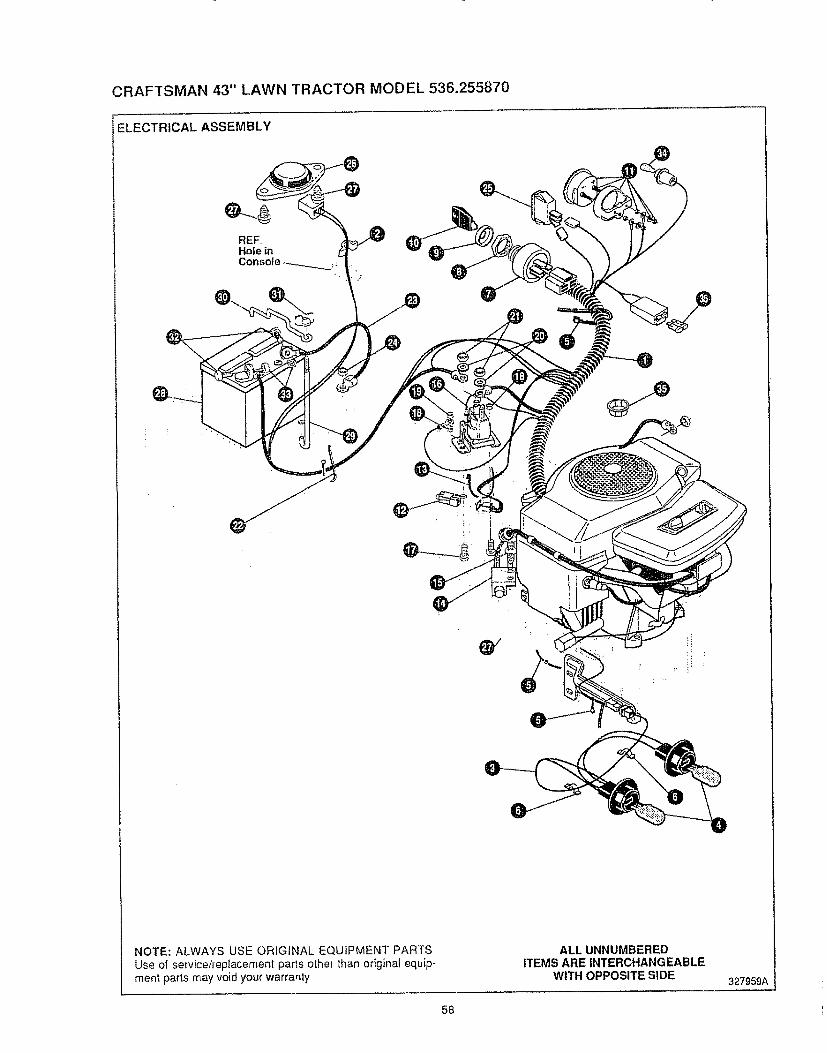
CRAFTSMAN 43" LAWN TRACTOR MODEL 536.255870
ELECTRICAL ASSEMBLY
NOTE: ALWAYS USE ORIGINAL EQUIPMENT PARTSUse of service/replacement parts other than origina! equip_ment parts may void your warranty
ALLUNNUMBEREDITEMS AREINTERCHANGEABLE
WITH OPPOSITESIDE 327959A
58
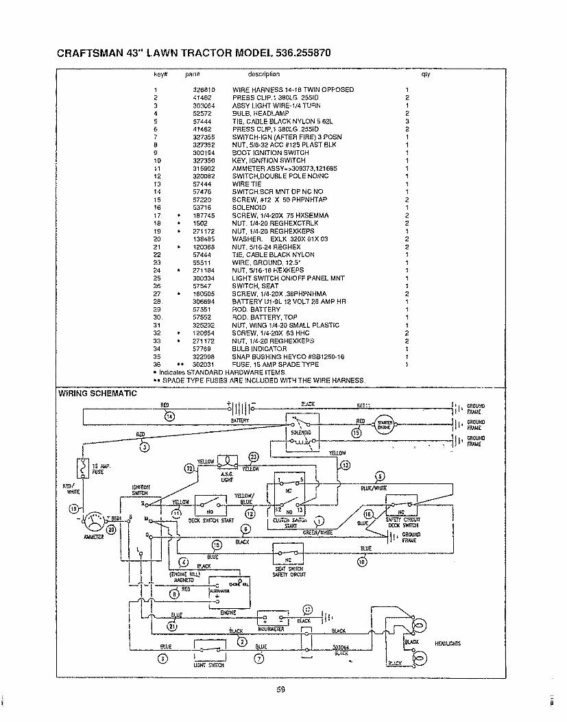
CRAFTSMAN 43" LAWN TRACTOR MODEL 536.255870
key#-, part# description qly
1 3268102 41482
3 303064
4 525725 57444
6 41482
7 3273558 327352
9 300194t0 327350
tt 315902
12 32008213 5744414 57476
15 5722016 53716
17 = 18774518 • 1502
19 * 27117220 138485
21 • 120368
22 5744423 55511
24 • 27118425 300334
26 5754727 * 160505
28 30669429 57551
30 57552
3t 325232
32 • 12085433 • 271172
34 57769
35 32299836 o_ 302031
WIRE HARNESS 14-t8 TWIN OPPOSEDPRESS CLIP.I 380LG 255ID
ASSY.LtGHT WIREd/4 TURN
BULB, HEADLAMP
TIE, CABLE BLACK NYLON 5 62LPRESS CLIP,t .380LG .2551D
SWtTCH-IGN.(AFTER FIRE) 3 POSNNUT, 5/8-32 ACC #125 PLAST BLKBOOT IGNITION SWITCH
KEY, IGNITION SWITCH
AMMETER ASSY_>309373,121685SWITCH,DOUBLE POLE NO/NCWIRE TIESWITCH.SCR MNT DP NC NO
SCREW, #12 X 50 PHPNHTAPSOLENOID
SCREW, t14-20X .75 H×SEMMANUT. 114-20 REGHEXCTRLK
NUT, 1/4-20 REGHEXKEPSWASHER. EXLK 320X 61X 03
NUT, 5/16-24 REGHEX
TIE, CABLE BLACK NYLON
WIRE, GROUND, 12,5"NUT, 5tt6-I8 HEXKEPSLIGHT SWITCH ON/OFF PANEL MNT
SWITCH, SEATSCREW, I14-20X .38PHPNHMABA'i-rERY ut-gL 12 VOLT 28 AMP HR
ROD, BATTERY
ROD. BATTERY, TOP
NUT, WING 1/4-20 SMALL PLASTICSCREW, 1/4-20X ,63 HHC
NUT, 1/4-20 REGHEXKEPSBULB,INDICATORSNAP BUSHING HEYCO #SB1250-16
FUSE, 15 AMP SPADE TYPE
12
12
3
21
1
11
11
11
2
12
2
12
2
1t
11
t2
11
1
1
221
t1
_' tndicates STANDARD HARDWARE ITEMS.
*_' SPADE TYPE FUSES ARE INCLUDED WiTH THE WIRE HARNESS
t
59
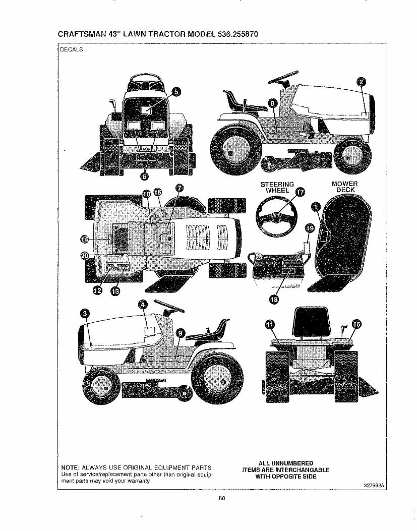
CRAFTSMAN 43" LAWN TRACTOR MODEL 536.255870
DECALS
STEERINGWHEEL
MOWERDECK
NOTE: ALWAYS USE ORIGINAL EQUIPMENT PARTS
Use of service#ep_acement parts other than original equip-ment parts may void your warranty
ALL UNNUMBEREDITEMS ARE INTERCHANGABLE
WITH OPPOSITE SIDE
327962A
60
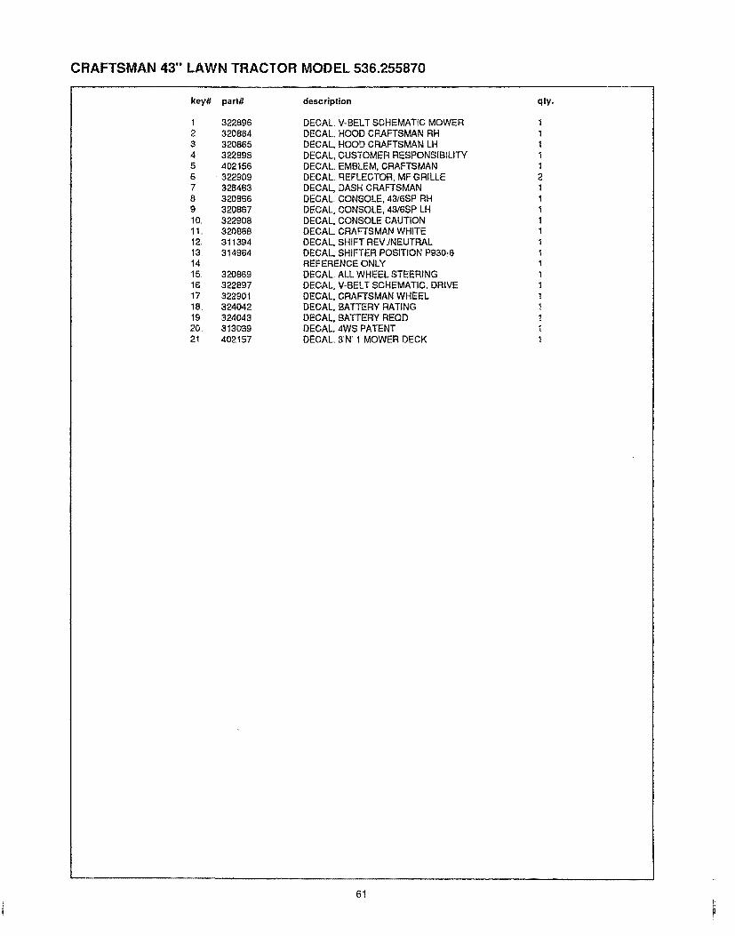
CRAFTSMAN 43" LAWN TRACTOR MODEL 536.255870
key'# part# description
1 3228962 3208643 3208654 3228985 4021566 3229097 3284838 3208669 32086710. 3229081t.. 320868t2. 311394t3 314964I4t5 320869t6 32289717 32290118 32404219 32404320 3130392! 402157
DECAL V-BELT SCHEMATIC MOWERDECAL, HOOD CRAFTSMAN RHDECAL, HOOD CRAFTSMAN LHDECAL, CUSTOMER RESPONSIBILITYDECAL. EMBLEM, CRAFTSMANDECAL. REFLECTOR, MF GRILLEDECAL, DASH CRAFTSMANDECAL. CONSOLE, 4316SP RHDECAL, CONSOLE, 4316SP LHDECAL, CONSOLE CAUTIONDECAL. CRAFTSMAN WHITEDECAL, SHIFT REVINEUTRALDECAL, SHIFTER POSITION P930-6REFERENCE ONLYDECAL. ALL WHEEL STEERINGDECAL, V-BELT SCHEMATIC, DRIVEDECAL, CRAFTSMAN WHEELDECAL, BATTERY RATINGDECAL, BATFERY REQDDECAL. 4WS PATENTDECAL. 3N 1 MOWER DECK
qly,.
111t12tII1111ttt!t!tt
6t

CRAFTSMAN 43" LAWN TRACTOR MODEL 536.255870
CUSTOMER ASSEMBLY
CUSTOMER ASSEMBLY VIEW323357 PARTS BAG ASSY QTY1
key#
1234
part# decdption
306654
456378
301413
STEERING WHEELPiN SPRING ,250DIA X 2,00LGSPACER STEERING SHAFTBATTERY ACiD
" May Be Purchased Locally
62
qty
1t1t
323356_.... i

CRAFTSMAN 43" LAWN TRACTOR MODEL 536.255870
TREAD PATTERNS
w,A,v
TIRE SIZE "A" "B" "C" "D"
11 X 4,00 - 5
13 X5,00- 6
15 X 6 O0 - 6
16 X 6,50 - 818 X 8,50 - 8
18 X 9.50 - 8
20 X 8.00 - 8
42295 319679
41060 319680
39830 316702
41081 319682319683 317400
41106 316701
319685 319684
20 X 10.,00-8 58276 319686
20 X 1000-10 55893 319687
23 X 9,50-!2 53655 319690
301140
57164
319689
313952
314539
313950
314584
313654
314370
63
316711 B

ENGINE REPAIR PARTSENGINE MODEL 402707-1235-01 FOR 43" TRACTOR MODEL 536.255870
s.1 3 22
9
9 556_
1019 LABEL ,,,
REF, PARTNO NO. DESCRIPTION
1 494533 Cylinder Assembly2 491756 Bearing-Cylinder3 _391086 SeaF-Oi]
5.! 493457 Head-Cylinder #1
5.2 493458 Head-Cylinder #27,1 _271867 Gasket-Cylinder
Head #1
7.2 ;_271868 Gasket-CylinderHead #2
8_t 398085 Breather Assembly #18°2 222892 Cover-Breather
Cylinder #2
(Used Only on Ref,572 Air Baffle with
Holes for Mounting)9 _:27803 Gasket-Valve Cover
10 94382 Screw-Sem
11 280225 Tube-Breather
REE PARTNO. NO.
12 _271703
_271188
:_271189
13 94565
15 94239
15A 94497
18 493304
20 w291675
21 399195
22 93882
244 239318
354 90576
881
5.2
7.2
18 I 524AI"k REQUIRES SPECIAL TOOLS
TO INSTALL SEE REPAIR
{_20 _15A INSTRUCTION MANUAL,
REF. PARTDESCRIPTION
Gasket-Crankcase
Cover (1/64" Thick)Gasket-Crankcase
Cover (4005" Thick)Gasket-Crankcase
Cover (,.009" Thick)
Screw-Cylinder HeaFtPlug-,Oii Drain
Plug-Pipe (t/827)
Base Assy.-Crankcase
Seal-Oil
Plug Assy.--Oil FillScrew-Crankcase
Cover Mtg..
Connector--Impulse
PumpNut-Hexo
NO. NO. DESCRIPTION
506 231174 Terminal
507 280180 Grommet-Insulator
524A -_271485 Seal-Plug556 93585 Screw-Hex_ Hd569 _270981 Gasket.Crankcase
572 224580 Baffle-Air (CyL #2)869 261453 Seat-Intake Valve
(Standard)870 213316 Seat-Exhaust Valve
(Standard)871 26'1961 Guide-Exhaust Valve
(Only)Note: 231218 Guide-lntake
(Brass)See Repair Manual
881 222860 Cover Plate-
Crankcase1019 491261 Label Kit
Included in Gasket Set-Part No 491856,.
Assemblies include all parts shown In frames.
64

ENGINE MODEL 402707-1235-01 FOR 43" TRACTOR MODEL 536.255870
t*"
_[_ 615 q_
24 634A _)
552A _';
615
552
t_
616 H @ 220
230
219A
40 35
e 868,,2_ _' I_, -_ @_ "_
" 36 33
32
34819
26
REE PARTNO. NO. DESCRIPTION
42 93630 Retainer-Exhaust
Valve Rotocoil (2)
45 261368 Tappet-Valve
46 213421 Gear-Cam
219 393415 Oil Slinger Assembly219A 394348 Gear-Governor
220 222773 Washer-Thrust
230 223882 Washer-Gov,, Crank
(Inside)552 262332 Lower Bushing--Gow
552A 262331 Upper Bushing- Govo615 94296 Retainer-E-Ring
616 491530 Crank-Governor
634A -_491287 Seal-Governor Shaft
741 262694 Gear-Timing819 94675 Screw-Hex Hd.,
868 393606 Sea[ Assy, & Retainer
REE PART REE PARTNQ NOo DESCRIPTION NO., NO. DES(_RIPTION
16 27 260924 Lock-PistonPin
28 299691 Pin Assy--Piston(Standard)
391286 Pin Assembly-
393382 Crankshaft
Note: Order 94196 For
Timing Gear Key,
24 222698 Key-Flywheel
25 394955 Piston Assy,(Standard)
394956 Piston Assy.
(_OlO"o,£,)394957 Piston Assy
(,020" 03°)394958 Piston Assy
(.030" O,S,)PISTON RING SETS:
Piston (,005" OSo)29 492667 Rod Assembly-
ConnectingNote: ForConnectingRod
With.020" Undersize
CrankpinBore-OrderNo,,397158°
32 94671 Screw-ConnectingRod
26 394959 Ring Set-Piston
(Standard)
394960 Ring Set-Piston(.010" O,,S.)
394961 Ring Set-Piston
(.020"O,S,,)394962 Ring Set-Piston
(,030" O,,S.)
33 390420 Valve-Exhaust
34 261528 Valve-intake
35 65906 Spring-Intake Valve
36 26828 Spring-Exhaust Valve40 221596 Retainer-intake Valve
41 292260 RotocoiI-Exhaust
Valve
Included in Gasket Set-Part Nor 491856,
Assemblies include all parts shown In frames.
65

ENGINE MODE[. 402707-1235-01 FOR 43" TRACTOR MODEL 536.255870
358 GASKETSET !
[861 PUMP REPAIR KIT
19551..... I 98
859
392434 _117
REF PARTNO, NO. DESCRIPTION
50 213290 Manifold-Intake
51 _=271412 Gasket--Carburetor&Intake Elbow
51A 280319 Spacer-Carburetor52 _270884 Gasket-Intake
Manifold Mtg.53 93970 Screw-Hexo Head
(Carb to Manifold)54 93208 Screw-Intake
Manifold Mtg, Sem
90 495181 Carburetor Assembly91 495035 Body Assembly-Upper
Carburetor
93 231209 Bushing-Throttle Shaft
94 e491238 Valve Assembly-Carbureter Idle
95 93499 Screw-Valve Mtg.Sere
95 221939 Valve-Throttle
,08@ 109
102
104 103
_119
51
51A
51 52
205
_ 634
I 5254
_'1_'! CARBURETOR OVERHAUL KIT
REF PARTNO. NO. DESCRIPTION
REE PARTNO. NO. DESCRIPTION
202 262684 Link-Throttle
203 280997 Crank-Bell
205 93971 Screw-Hex,, Head
232 262539 Spring-Backlash358 491856 Gasket Set
387 280197 Body-Pump
392 ==261395 Spring-Pump
394 =270988 Diaphragm
432 ,.221377 Cap-Spring
434 223688 Cover-Diaphragm
435 93829 Screw-DiaphragmCover
634 e271013 Washer
(Throttle Shaft)
858 "270989 Diaphragm-Carb,
859 =271025 Gasket-Carb Pump
860 =261358 Spring (2)
861 393397 Repair Kit-Pump
955 397882 Plug and Seal-Solenoid
97 392672 Shaft and Lever-
Throttle
98 91920 Screw-Fi],, Hd,,
99 26157 Spring-Throttle Adj.102 m271607 Gasket-Carburetor
Body103 298514 Float-Carburetor
104 =230896 Pin-Roat Hinge105 =394683 Valve-Fuel Inlet
107 491543 Body-Lower Carb,,108 223534 Valve-Choke
109 392673 Shaft and Lever-
Choke
116 .280474 O-Ring117 231338 Jet-Needle Valve
(Fixed)
119 94152 Screw-Hex_ Hd.121 491539 Carburetor Overhaul
Kit
127 e223472 Plug-Welch
:k Included in Gasket Set-Part Ne. 491856o included in Carburetor Overhaul Kit-Part Ne, 491539.
= Included in Carburetor Overhaul Kit-Part No. 491539 and Pump Repair Kit-Part No. 393397,,
Assemblies include all parts shown in frames,
66
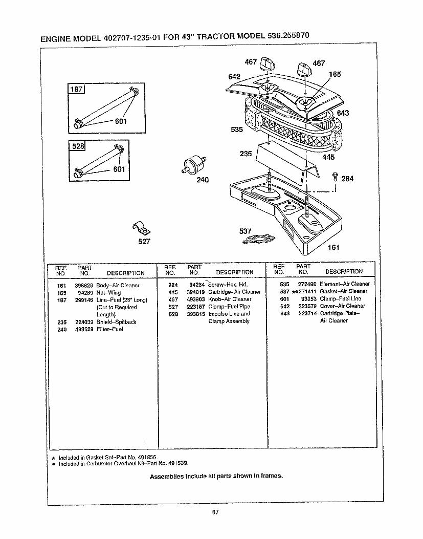
ENGINE MODEL 402707-1235-01 FOR 43" TRACTOR MODEL 536.255870
467
642
467
165
601
%527
240
535
235
643
445
284
161
REE PARTNO. NO., DESCRIPTION
161 398826 Body-Air Cleaner165 94289 Nut-Wing
187 299146 Line-Fuel (28" Long)
(Cut to Required
Length)235 224039 Shleld-Spjtback240 493629 Filter---Fuel
REF. PARTNO NO DESCRIPTION
284 g4264-Screw-Hex,, Hd_
445 394019 Cartridge-Air Cleaner467 493903 Knob-Air Cleaner
527 223167 Clamp-Fuel Pipe52B 393815 Impulse Lineand
Clamp Assembly
REF+ PARTNO, NO, DESCRIPTION
535 272490 Element-Nr Cleaner537 _-e271411 Gasket-Air Cleaner601 93053 Clamp--Fue! Line642 223579 Cover-Air Cleaner643 223714 CartridgePlate-
AirCleaner
:_ included in Gasket Set-Part No. 491856= Included in Carburetor Overhaul Kit-Part No+49153g.
Assembiles include all parts shown In frames+
67
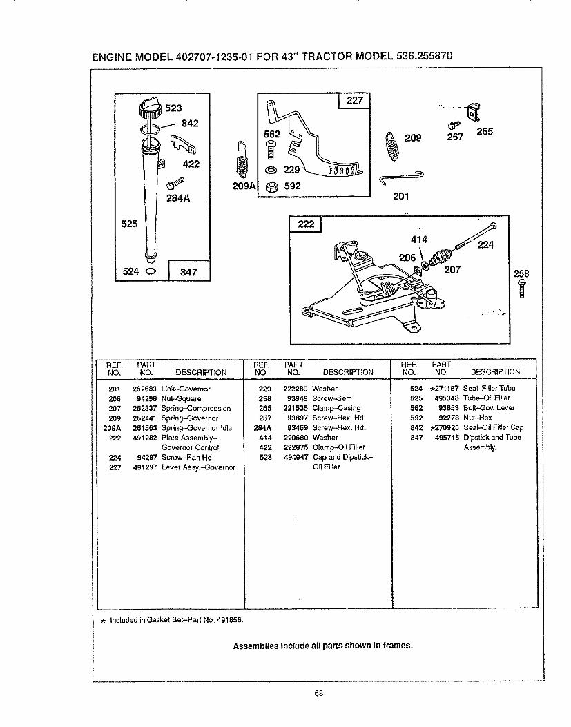
ENGINE MODEL 402707-1235-01 FOR 43" TRACTOR MODEL 536.255870
523
.I 842
%422
284A
525
524 C> [ 847
209A
229
t_ 592
209
201
265267
207
REE PART REE PART REE PARTNO. NO. DESCRIPTION NO. NO. DESCRIPTION NO. NO, DESCRIPTION
20i
2O62O7
209209A
222
224227
262683 Link-Governor
94298 Nut--Square262337 Spring-Compression
262441 Spring-Governor261563 Spring-Governor idle
491282 Plate Assembly-Governor Controt
94297 Screw-Pan Hd
491297 Lever Ass¥.-Govemor
229 222289 Washer258 93949 Screw-Sere
265 221535 Clamp-Casing267 93897 Screw-Hex. Hd
284A 93469 Screw-Hex_ Hd.
414 220680 Washer
422 222875 Clamp-Oil Fillet
523 494947 Cap and Dipstick-OilFiller
524 .271157 Seal-FillerTube525 495348 Tube-OilFitler562 93853 Bolt-Gov. Lever592 92278 Nut-Hex,.
842 *270920 Seal-Oil FillerCap847 495715 Dipstickand Tube
Assembly_
Included in Gasket Set-Part No. 491856.
Assemblies Include all parts shown In frames.
68

ENGINE MODEL 402707-1235-01 FOR 43" TRACTOR MODEL 536.255870
653
783513
544
1
803311
1003_
310
..... Reie;'enceNumber I 30g - 31o
Manufaclurer
........Briggs & Housing
Sttatton Length
12V 4-!t2"
311
Motor &
Drive
Assembly
399928""
510
Thru Boll Brush Starter
Assembly Assembly Drive
,Gro,up.......
94169 " 4903ii ....... 490421 ;°''''
544
Armature
Assembly
490309
801 8O2 803. =
Drive End End Cap Housing
Csp Assembly Assembly
Assembly Commutator
394860 490310' 398892
1003
Brush
Spring
" InctudesBrush Set"* Includes #398003 Ciutch Assemb_y
#280104 Gear#490467 Retainer and Pin#94288 Roll Pin
"** Uses #93585 Screw-Hex, Hal,
Refo No, 513)Ref,, No,, 783)Ref., No, 876)Refo No 896)Ref No, 653)
Assemblies Include all parts shown in frames,
69

ENGINE MODEL 402707-1235-0'1 FOR 43" TRACTOR MODEL 536,255870
468
) 332
75
168
1006
REF, PARTNO. NO. DESCRIPTION
23 491180 Flywheel and RingGear Assy,-Magneto
75 222511 Washer-Spring78 94326 Screw-Sere
189 93535 Screw332 230674 Nut-Hex,
333 394891 Armature GIoup334 93381 Screw-Armature
M_g,,Sere
337 802592 Pfug-Spark
334851
482
35352O
354
337
_635
363
383
REE PARTNO. NO. DESCRIPTION
353 92791 Washer-Lock
354 90576 Nut-Hex,356 398874 Wire-Ground
363 19203 Puller-Flywheel
383 89838 Wrench-Spark P_ug468 224521 Screen-Flush Rotating
474 393474 Stator-Ntemato_"
(Due| Circuit)482 93621 Screw-Sem
520 93722 Terminal Spade
REE, PARTNO. NO, DESCRIPTION
635 86538 E_bow-Spark Plug
726 391362 Gear-Flywheel Ring
(Includes MountingParts),
851 221798 Terminat-lgnitionCable
877 393456 Diode and Connector
Assembly1005 280815 Far_FIywheel
1006 224413 Retainer-Fan
Assemblies Include all parts shown In frames.
7O
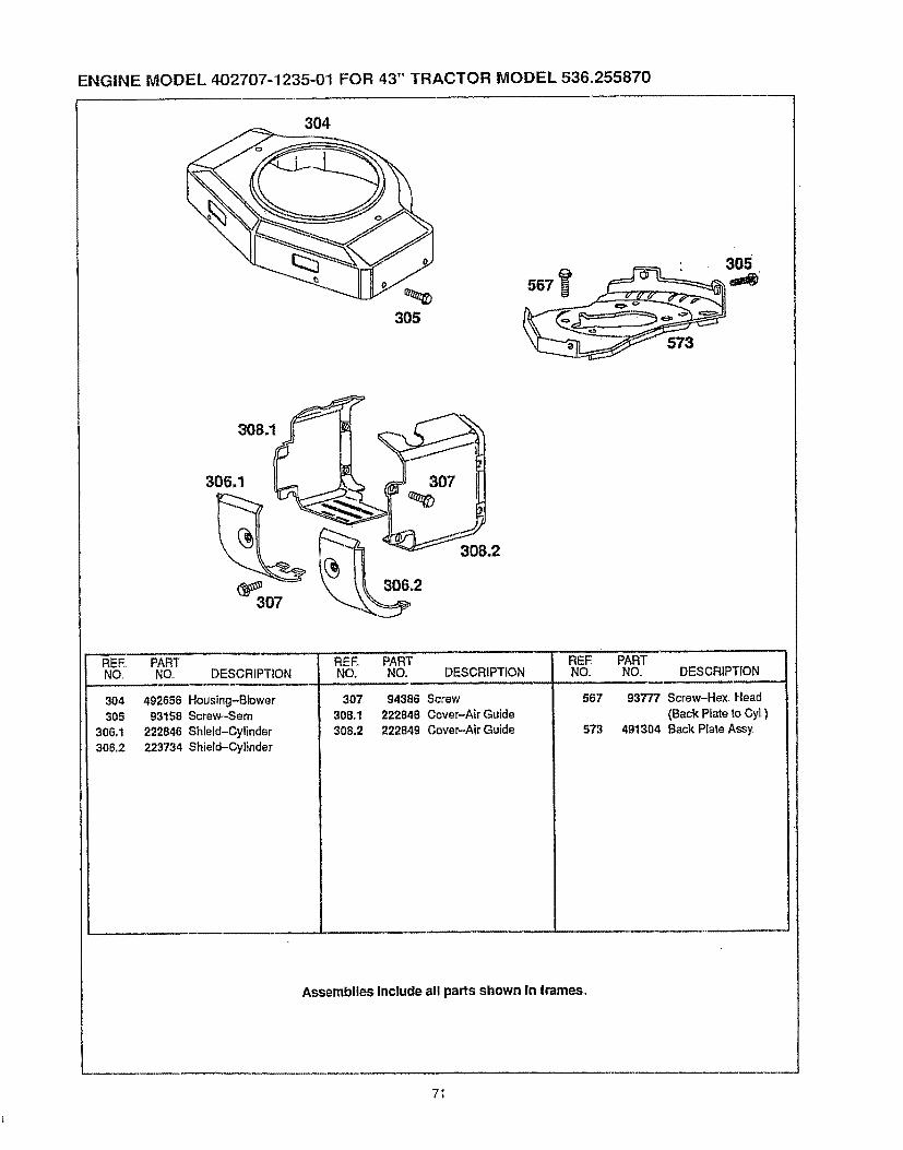
ENGINE MODEL 402707-1235-01 FOR 43" TRACTOR MODEL 536.255870
304
305
567
573
305
3o8.1
REF_ PART REE PART PARTNO. NO.. DESCRIPTION NO, NO. DESCRIPTION NO. DESCRIPTION
304 492656 Housing-Blower305 93158 Screw-Sem
306_1 222846 Shield-Cylinder
306.2 223734 Shield-Cylinder
307 94386 Screw
308.1 222848 Cover-Air Guide308,2 222849 Cover-Air Guide
REENO.
567
S73
93777 Screw-Hex. Head
(Back Prate to CyL)491304 Back Plate Assy,
AssembliesInclude all parts shown in frames°
7I

TRANSAXLE REPAIR PARTS
PEERLESS TRANSAXLE MODEL 930-045 FOR 43" TRACTOR MODEL 536.255870
6834
57
72

PEERLESS TRANSAXLE MODEL 930-045 FOR 43" TRACTOR MODEL 536.255870
KeyNo,
123
6789
101112131415t7182021222325
2627282930313233343536373839404142
Part No,
772108A780086
770102A77626O
776219A778139778136792136784352784355778229
778113A778221778068778260786139786102792077792078792079788061792073
792125792035788O4O78OO72780108780001792001788051
780105A780118A
790003790007
79O21786O26
792076A790023A
792085
Description
Cover, TransaxleBearing, NeedleCase, TransaxfeShaft, CounterShaft & Pinion Assembly, OutputGear. Ou!putGear. Spur (I5 teeth)KeyCollar, ShifterRod & Fork Assembly, ShiftGear, Bevel (42 teeth)Bevel Pinion, InputGear, Bevel (16 Teeth)Gear, Bevel PinionGear, RingPin, DriveSpacerBall, Steel (5/16_ Dia.)Set Screw, 3t8o16 x 3/8SpringRing, SealScrew, Flanged Hex Hd,Thread forming, 114-20 x t-1/4Ring, Retainer (Pkg. of 2)Ring, RetainerRing, RetainerWasher, ThrustWasher, ThrustWasher"0" RingSeal, Square cutBushing, FlangedBushing, FlangedDisk, BrakePlate, Brake padPad, Brake (Pkg. of 2)Pin, DowelWasher, FiatLever, BrakeScrew, Flanged Hex Hd,Thread forming, 1/4-2o x 2-1/4
KeyNo, Part No.
43 79207544 79OO2545 786O6646 786O8647 77495148 77495249 7781835O 778124A51 77825052 778123A53 778121A56 77819357 778126A58 77824959 778127A60 778129A63 78607164 78607265 78010966 77613567 776315A68 78611669 78OO517O 7861'187! 78806972 79207476 78009077 788078A81 786062A82 78606183 7861249O 788067B
150 510334
Description
Nut, Lock, 5t16_24Holder, Brake padSpacerBrake Lever BracketAxle (8-15/16" long)Axle (13-17/32" long)Gear, Spur (35 teeth)Gear, Spur (30 teeth)Gear, Spur (27 teeth)Gear, Spur (25 teeth)Gear, Spur (20 teeth)Gear, Spur (15 teeth steel)Gear, Spur (20 teeth)Gear, Spur (23 teeth)Gear, Spur (25 teeth)Gear, Spur ( 30 teeth)Countershaft SpacerOutput Shaft SpacerWasherInput ShaftShifter & Brake ShaftDiskWasherSpacerSquare Cut RingThreaded PlugWasherInverted Retaining Ring (pkg..of 2)Roller Chain (No..41 chain, 22 links)Sprocket (I0 teeth)Reverse Sprocket (14 teeth)Grease (32 oz_.btl. Bentonite grease)Gasket Eliminator (Loctite #515)
" THIS TRANSAXLE'S CAPACITY IS 24 OZ.
73

OWNER'SMANUAL
MODEL NO.
536.255870
HOW TO ORDERREPAIR PARTS
CRRFTSMRII15.0 HP TWIALL=WHEEL43" MOWER
CYL!STEERDECK
DER
6.-SPEED TRANSAXLELAWN TRACTOR
Eachtractor has itsown model number Each engine has itsown r:nodelnumber
The Model Number for your tractor will be found on the model platelocated under the seat
The model number for your engine will be fou nd on the blower housingof the engine
All parts may be ordered through Sears, Roebuck and CompanyService Centers and most Retail Stores,
WHEN ORDERING REPAIR PARTS, ALWAYS GIVE THE FOLLOW-ING INFORMATION:
o PRODUCT - LAWN TRACTOR
o MODEL NUMBER - 536.255870
• ENGINE MODEL NUMBER., 402707-1235-01
• PART NUMBER
o PART DESCRIPTION
Your Sears merchandise has added value when you consider Searshas service units nationwide staffed with Sears trained technicians ,professional technicians specifically trained to insure that we meetour pledge to you, we service what we sell,
SEARS, ROEBUCK AND CO., D/817WA, HOFFMAN ESTATES, IL 60179
327865 03/12/93 Printed in U S A