Embed Size (px)
Citation preview

Crossing StructuresCrossing Structures
• Crossing structures are those Crossing structures are those constructed at intersections of:constructed at intersections of:
1. Waterway-road (culvert or bridge).1. Waterway-road (culvert or bridge).
2. Waterway-Waterway (syphon or 2. Waterway-Waterway (syphon or aqueduct).aqueduct).
3. Waterway ending at another 3. Waterway ending at another waterway (tail escape).waterway (tail escape).

Syphon or Aqueduct
Waterway
Waterway
Culvert or Bridge
Road
Waterway
Tail escape
Waterway
Waterway

CulvertCulvert

The culvert is a closed conduit (pipe The culvert is a closed conduit (pipe or box section) constructed to carry or box section) constructed to carry the discharge of a waterway under the discharge of a waterway under a road.a road.
The selection of the type of the The selection of the type of the culvert is based on the discharge as culvert is based on the discharge as follows:follows:
• For Q ≤ 3.0 mFor Q ≤ 3.0 m33/sec use Pipe culvert./sec use Pipe culvert.
• For Q ≤ 12.0 mFor Q ≤ 12.0 m33/sec use Box /sec use Box section. section.

≤ .15 m
d
≥ .3 m
D
HS

Hydraulic DesignHydraulic Design
The purpose of the hydraulic design is The purpose of the hydraulic design is to select the culvertto select the culvert’’s dimensions.s dimensions.
The dimensions are selected based on:The dimensions are selected based on:
• Velocity through culvert between 1.0 Velocity through culvert between 1.0 to 2.0 m/sec.to 2.0 m/sec.
• Head losses is less then 15 cm.Head losses is less then 15 cm.
• Entrance submergence is at least 30 Entrance submergence is at least 30 cm.cm.

The only equation available is the The only equation available is the continuity equation:continuity equation:
Q = A . VQ = A . VWhere Q is the discharge in mWhere Q is the discharge in m33/sec, A is /sec, A is
the culvertthe culvert’’s cross section area in ms cross section area in m22,, and V is the water velocity through the and V is the water velocity through the culvert in m/sec. Since the discharge culvert in m/sec. Since the discharge is known, the velocity must be is known, the velocity must be assumed to determine the dimensions assumed to determine the dimensions of the culvert. The velocity is usually of the culvert. The velocity is usually assumed between 1.0 and 2.0 m/sec assumed between 1.0 and 2.0 m/sec for practical reasons.for practical reasons.

Once the dimensions are determined, Once the dimensions are determined, then head losses must be checked. then head losses must be checked. Head losses are calculated as Head losses are calculated as follows,follows,
Where HWhere Hll is the head losses in m is the head losses in m
V is the velocity in m/secV is the velocity in m/sec
g is the acceleration of gravityg is the acceleration of gravity
)(2
2
ofel CCCg
VH
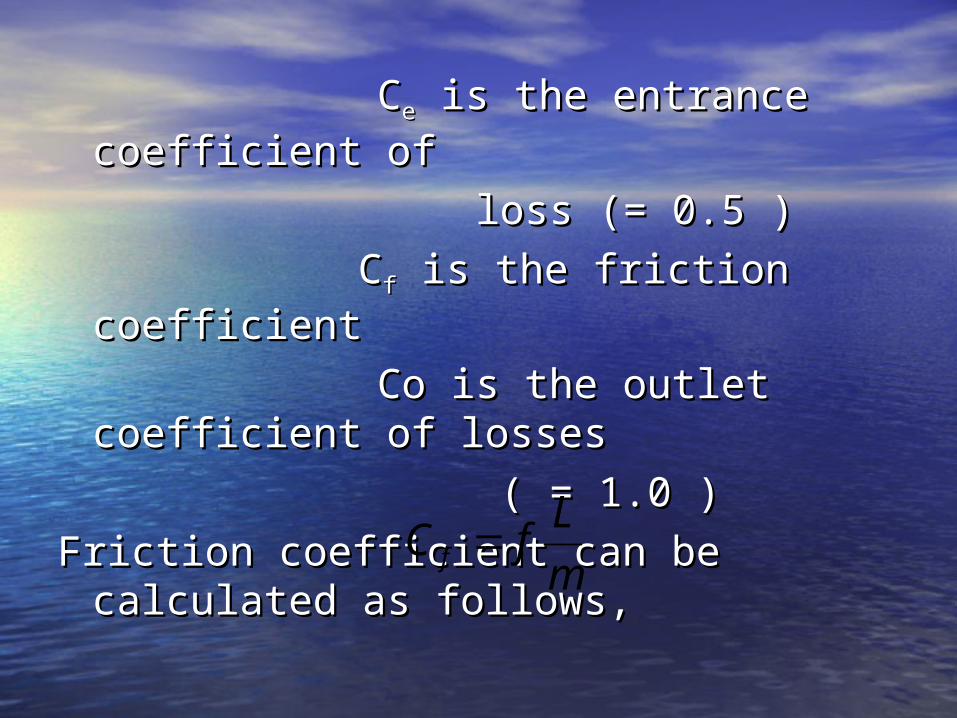
CCee is the entrance coefficient is the entrance coefficient of of
loss (= 0.5 )loss (= 0.5 )
CCff is the friction coefficient is the friction coefficient
Co is the outlet coefficient of Co is the outlet coefficient of losses losses
( = 1.0 )( = 1.0 )
Friction coefficient can be calculated Friction coefficient can be calculated as follows,as follows, m
LfC f

Where f is coefficient depends on the Where f is coefficient depends on the culvert material and dimension, L is the culvert material and dimension, L is the length of the culvert and m is the length of the culvert and m is the hydraulic radius.hydraulic radius.
The coefficient a and b are constant and The coefficient a and b are constant and depends on the material of the conduit.depends on the material of the conduit.
For Steel: a = 0.0048, b = 0.0256For Steel: a = 0.0048, b = 0.0256For Concrete: a = 0.00316, b= 0.0305For Concrete: a = 0.00316, b= 0.0305
)1(m
baf

• Example 1:Example 1:Design a culvert under a road. The Design a culvert under a road. The discharge is 3 mdischarge is 3 m33/sec and the water /sec and the water depth is 1.8 m. The culvert length is depth is 1.8 m. The culvert length is 20 m.20 m.
• Sol.Sol.Q = 3 m3/sec * use pipe culvertQ = 3 m3/sec * use pipe culvertassume V=1.3 m/secassume V=1.3 m/secA = Q/V = 2.31 mA = Q/V = 2.31 m22
A = ∏ DA = ∏ D22/4 * D = 1.7 m/4 * D = 1.7 mHowever, D ≤ 1.8 – 0.3 … 1.5 mHowever, D ≤ 1.8 – 0.3 … 1.5 m
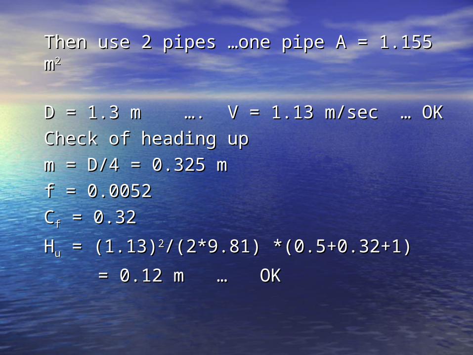
Then use 2 pipes Then use 2 pipes ……one pipe A = 1.155 one pipe A = 1.155 mm22
D = 1.3 m D = 1.3 m ……. V = 1.13 m/sec . V = 1.13 m/sec …… OK OK
Check of heading upCheck of heading up
m = D/4 = 0.325 mm = D/4 = 0.325 m
f = 0.0052f = 0.0052
CCff = 0.32 = 0.32
HHuu = (1.13) = (1.13)22/(2*9.81) *(0.5+0.32+1)/(2*9.81) *(0.5+0.32+1)
= 0.12 m = 0.12 m …… OK OK
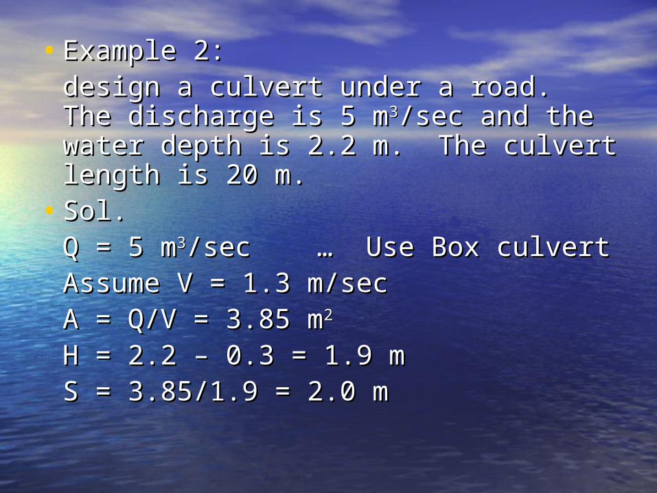
• Example 2:Example 2:design a culvert under a road. The design a culvert under a road. The discharge is 5 mdischarge is 5 m33/sec and the water /sec and the water depth is 2.2 m. The culvert length is depth is 2.2 m. The culvert length is 20 m.20 m.
• Sol.Sol.Q = 5 mQ = 5 m33/sec /sec …… Use Box culvert Use Box culvertAssume V = 1.3 m/secAssume V = 1.3 m/secA = Q/V = 3.85 mA = Q/V = 3.85 m22
H = 2.2 H = 2.2 –– 0.3 = 1.9 m 0.3 = 1.9 mS = 3.85/1.9 = 2.0 mS = 3.85/1.9 = 2.0 m
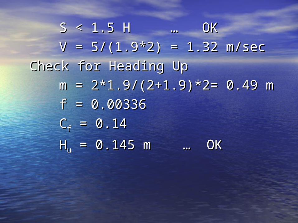
S < 1.5 H S < 1.5 H …… OK OK
V = 5/(1.9*2) = 1.32 m/secV = 5/(1.9*2) = 1.32 m/sec
Check for Heading UpCheck for Heading Up
m = 2*1.9/(2+1.9)*2= 0.49 mm = 2*1.9/(2+1.9)*2= 0.49 m
f = 0.00336f = 0.00336
CCff = 0.14 = 0.14
HHuu = 0.145 m = 0.145 m …… OK OK