Embed Size (px)
DESCRIPTION
Cross-talk in strip RPCs. D. Gonzalez-Diaz, A. Berezutskiy and M. Ciobanu with the collaboration of N. Majumdar, S. Mukhopadhyay, S. Bhattacharya (thanks to A. Blanco for providing us with HADES cells) 10-03-2009. Index. 1. Single strip parameters and the RPC as a current generator. - PowerPoint PPT Presentation
Citation preview

Cross-talk in strip RPCs
D. Gonzalez-Diaz, A. Berezutskiy and M. Ciobanu
with the collaboration of N. Majumdar, S. Mukhopadhyay, S. Bhattacharya
(thanks to A. Blanco for providing us with HADES cells)
10-03-2009
Index
1. Single strip parameters and the RPC as a current generator.
2. The induction profile.
3. The Boundary Element Method (BEM).
4. Propagation.
5. Conclusions.
1. Single strip parameters and the RPC as a current generator.
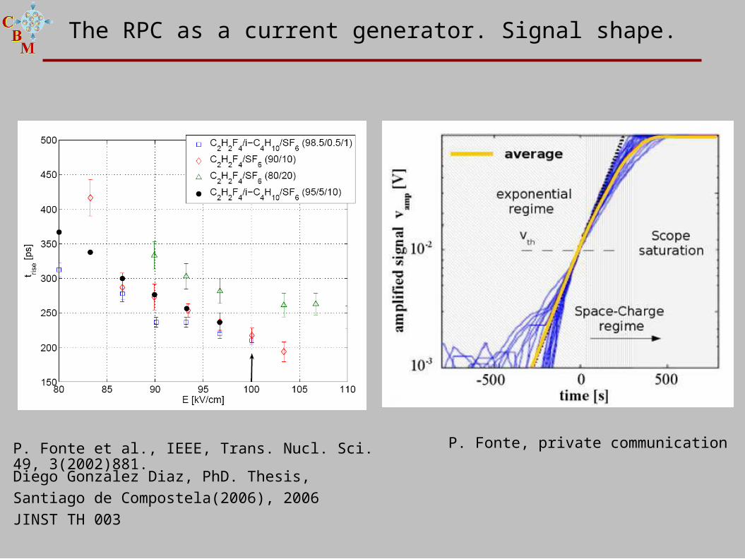
The RPC as a current generator. Signal shape.
P. Fonte, private communicationP. Fonte et al., IEEE, Trans. Nucl. Sci. 49, 3(2002)881.Diego Gonzalez Diaz, PhD. Thesis, Santiago de Compostela(2006), 2006 JINST TH 003
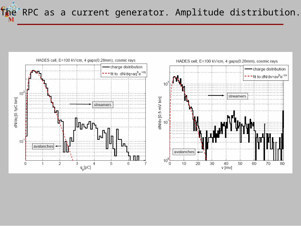
The RPC as a current generator. Amplitude distribution.
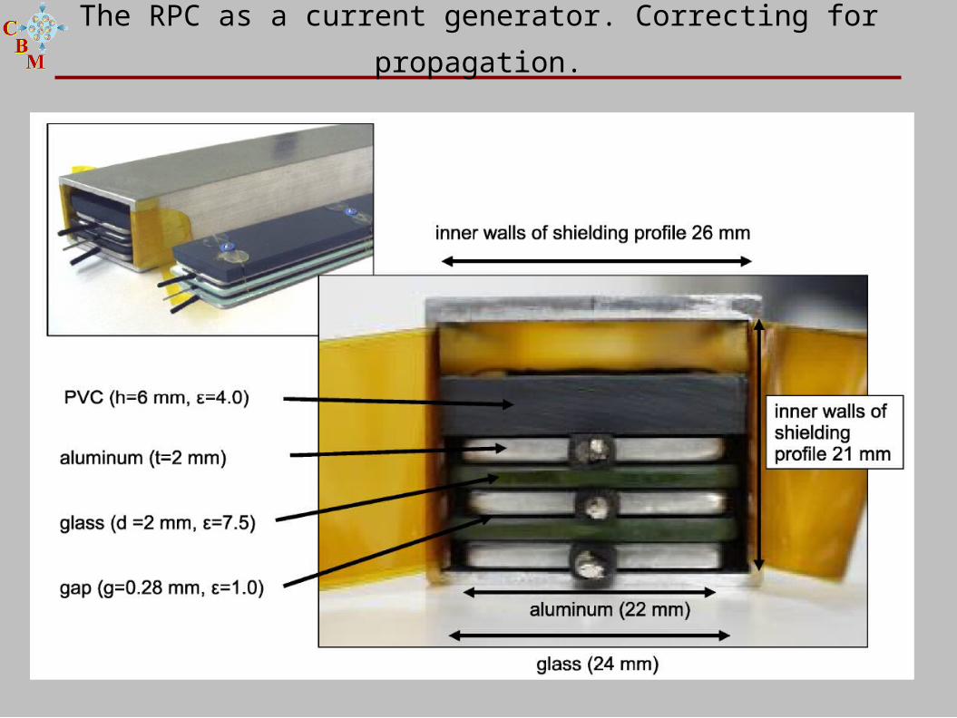
The RPC as a current generator. Correcting for propagation.
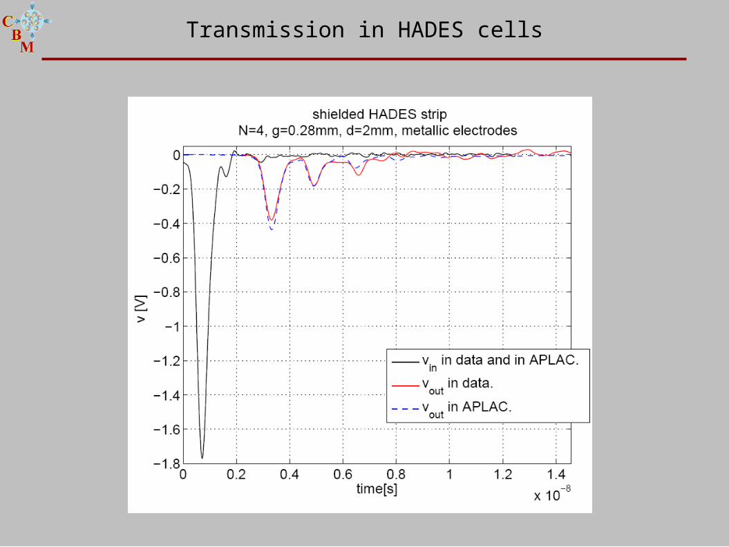
Transmission in HADES cells
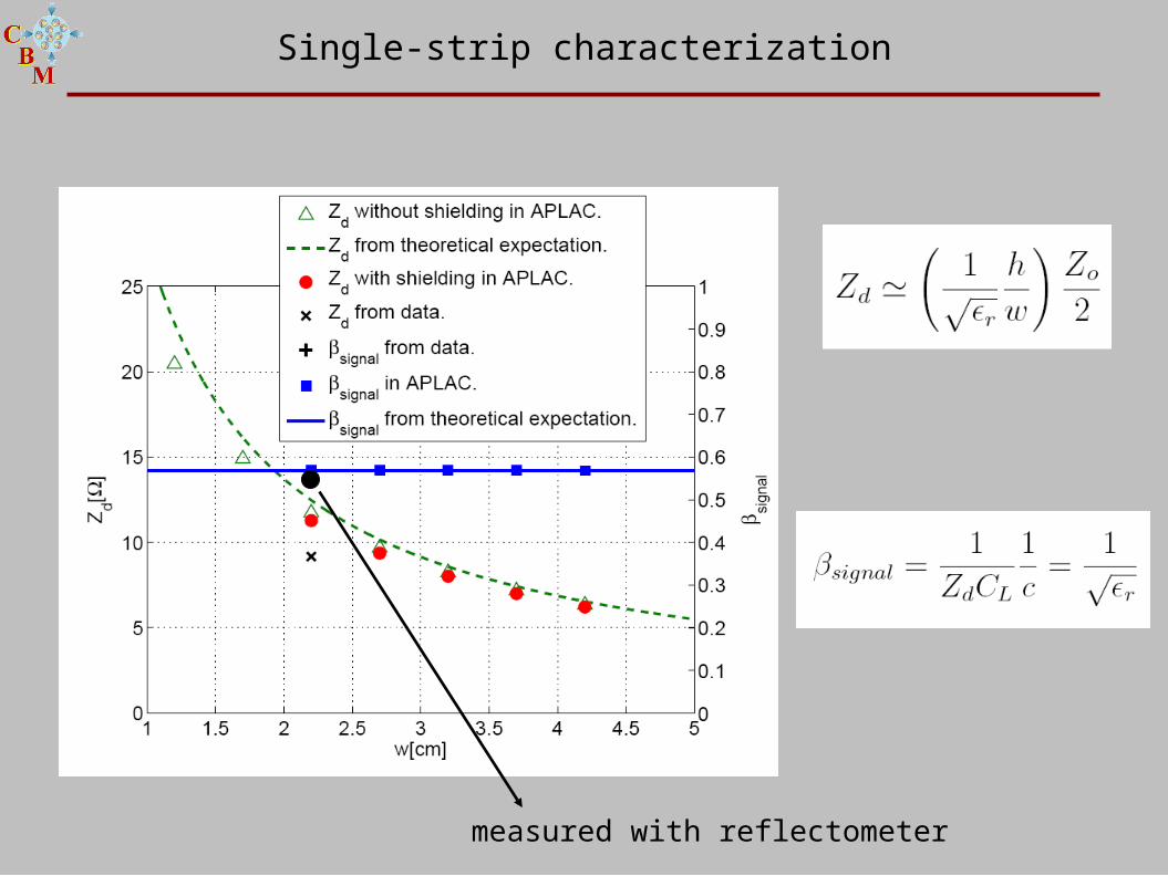
Single-strip characterization
measured with reflectometer
2. The induction profile.
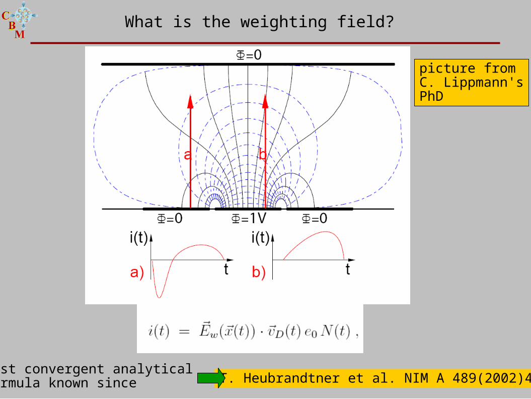
picture fromC. Lippmann'sPhD
T. Heubrandtner et al. NIM A 489(2002)439fast convergent analytical formula known since
What is the weighting field?
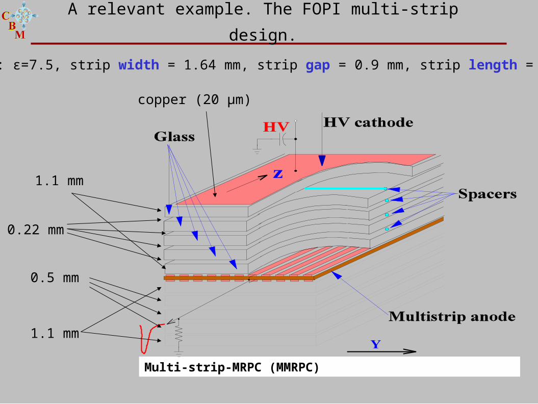
Multi-strip-MRPC (MMRPC)
1.1 mm
Glass: ε=7.5, strip width = 1.64 mm, strip gap = 0.9 mm, strip length = 900 mm
1.1 mm
0.5 mm
0.22 mm
copper (20 μm)
A relevant example. The FOPI multi-strip design.
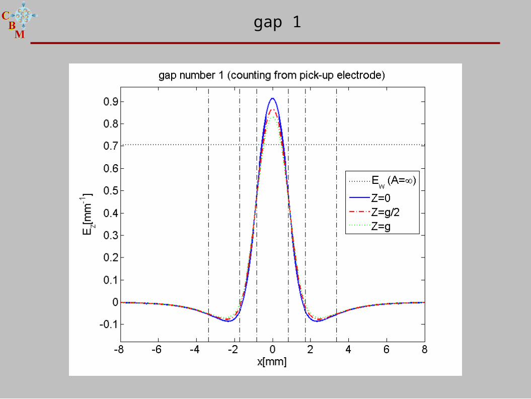
gap 1
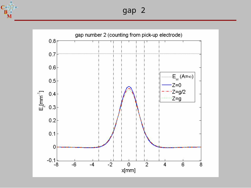
gap 2
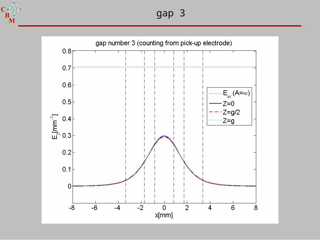
gap 3
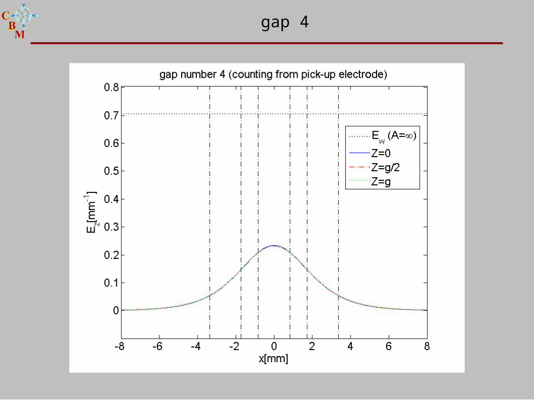
gap 4
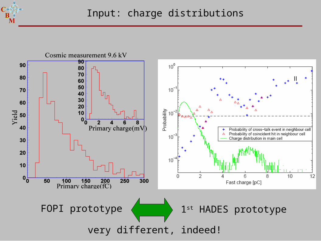
1st HADES prototypeFOPI prototype
Input: charge distributions
very different, indeed!
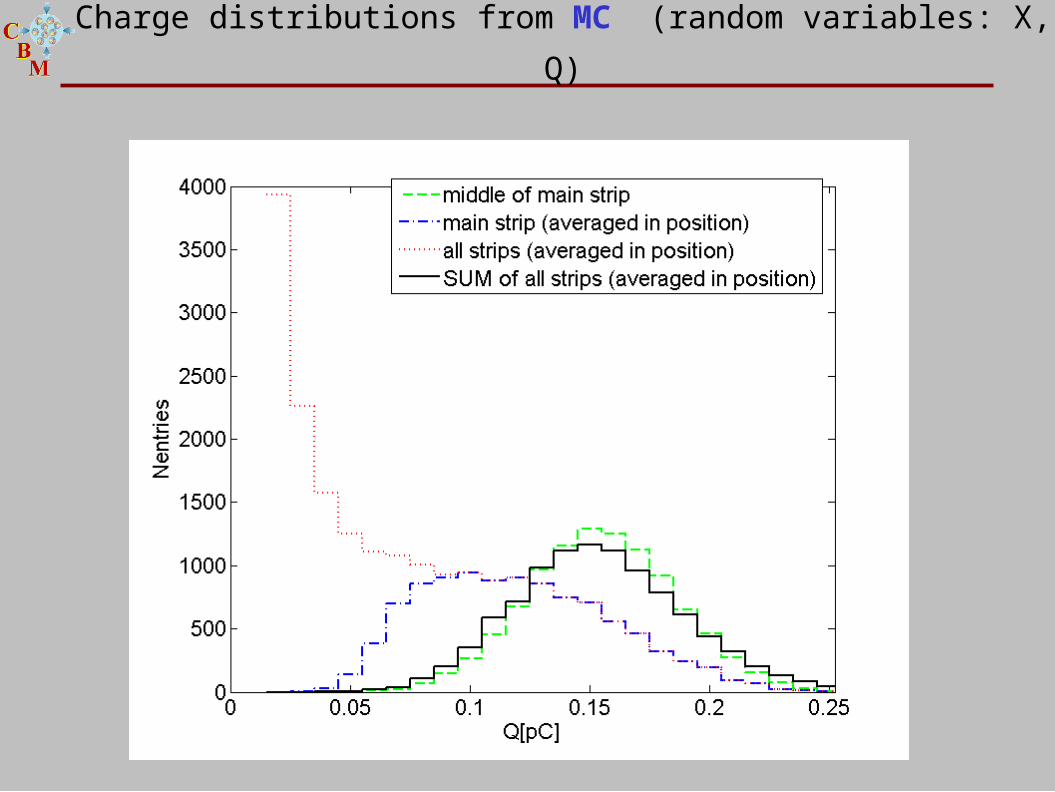
Charge distributions from MC (random variables: X, Q)
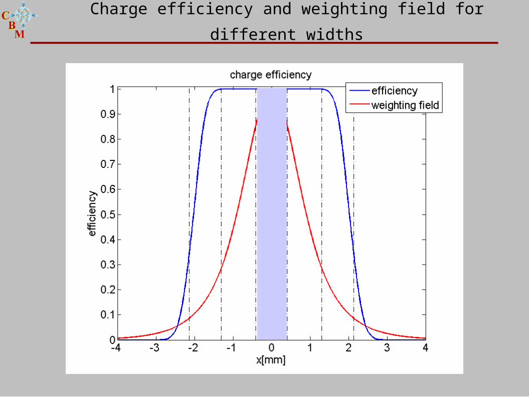
Charge efficiency and weighting field for different widths
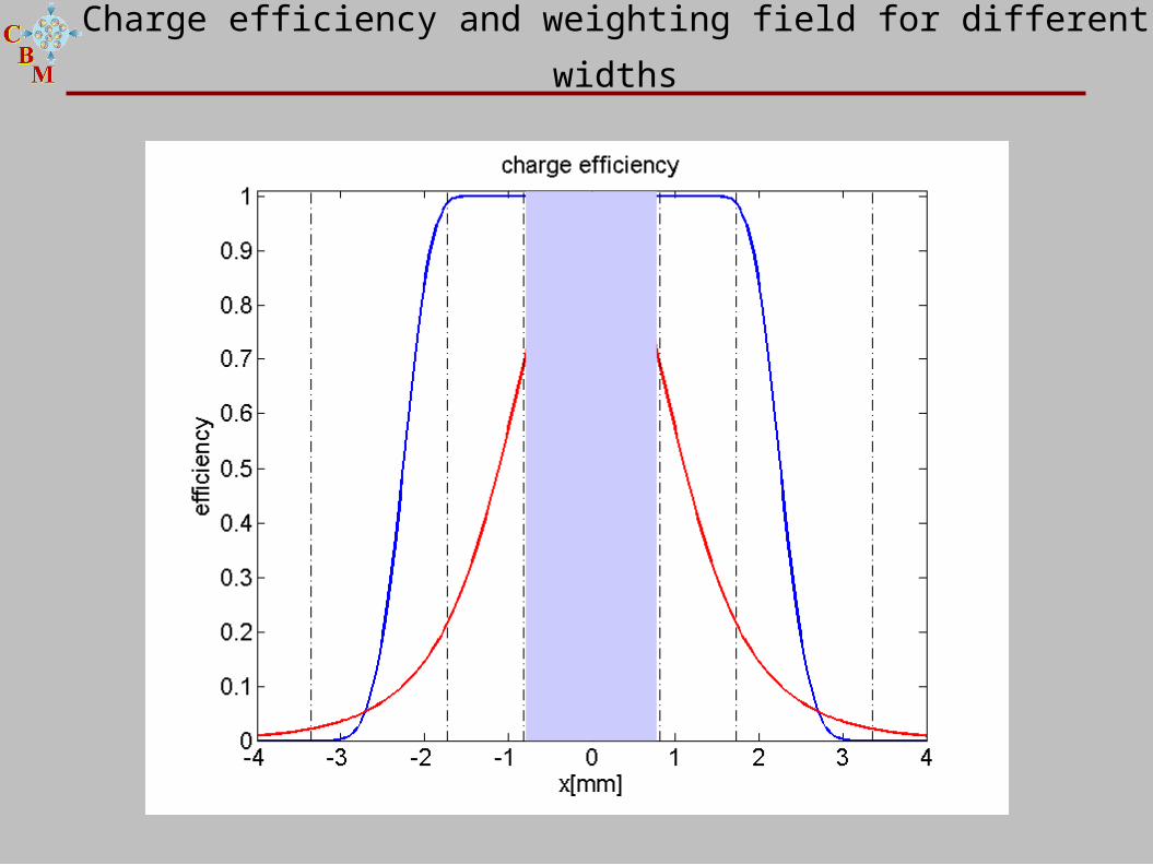
Charge efficiency and weighting field for different widths
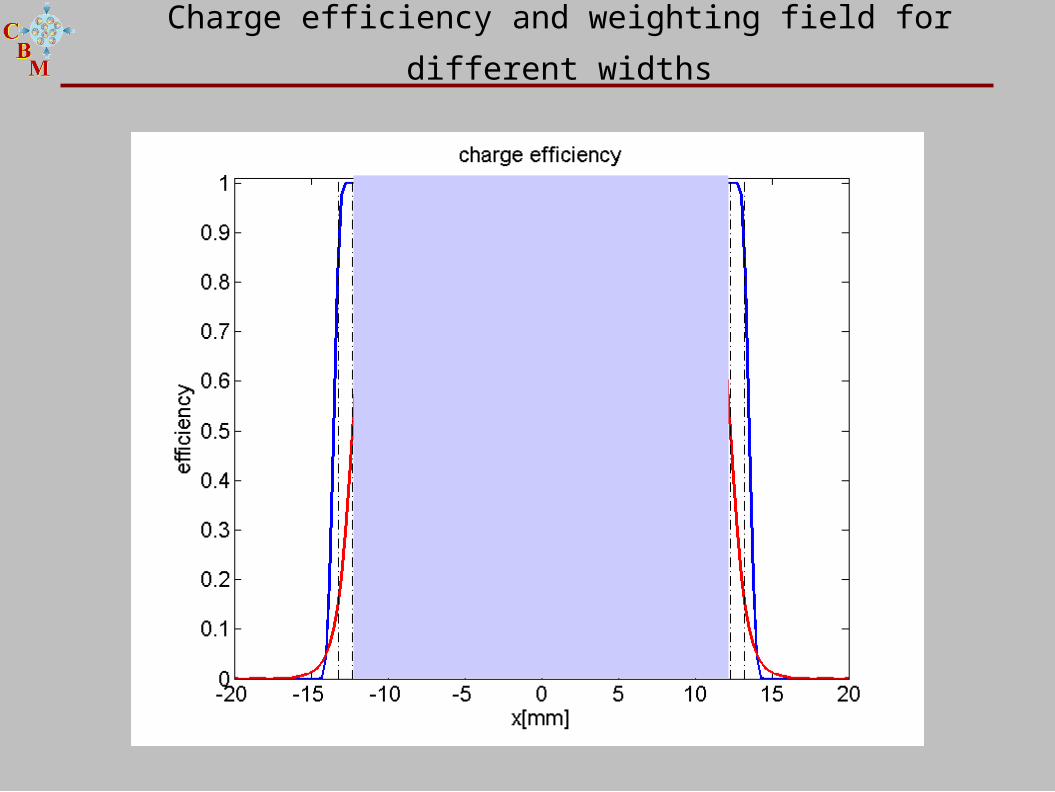
Charge efficiency and weighting field for different widths
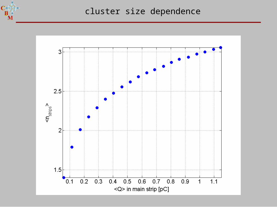
cluster size dependence
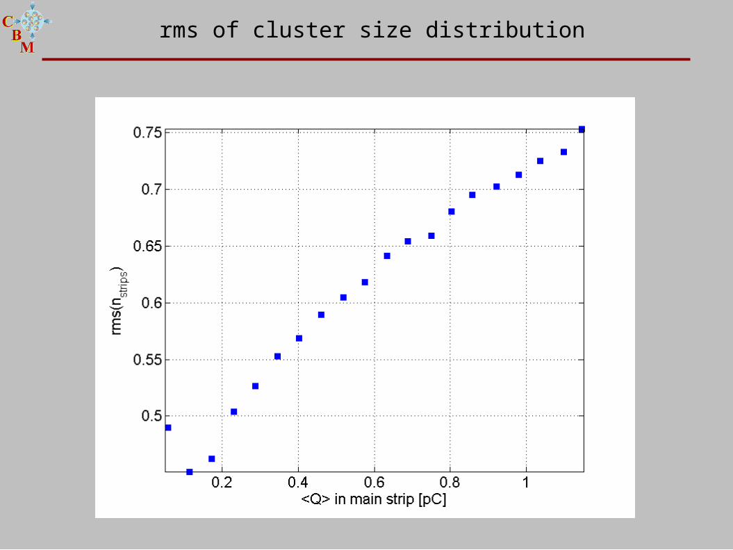
rms of cluster size distribution
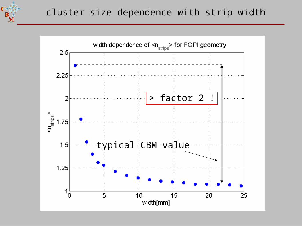
cluster size dependence with strip width
> factor 2 !
typical CBM value
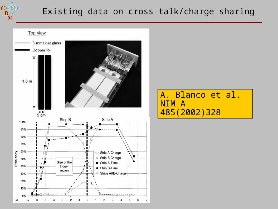
Existing data on cross-talk/charge sharing
A. Blanco et al.NIM A 485(2002)328
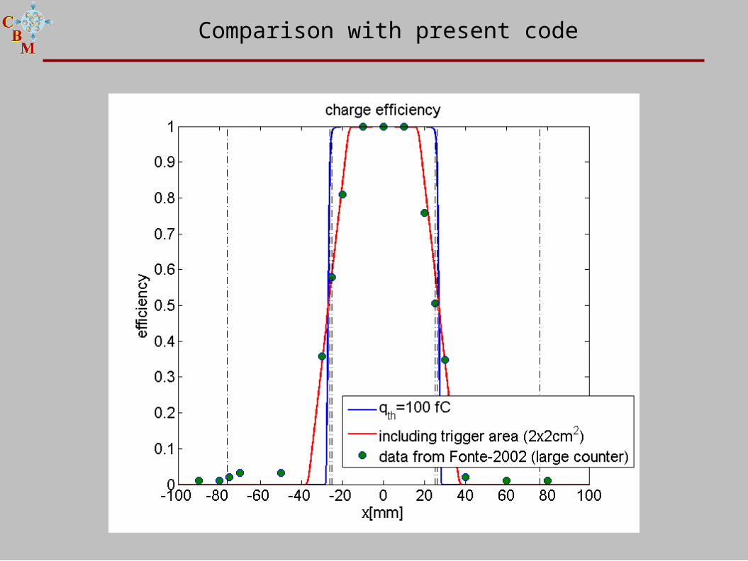
Comparison with present code
3. Boundary Element Method (BEM).
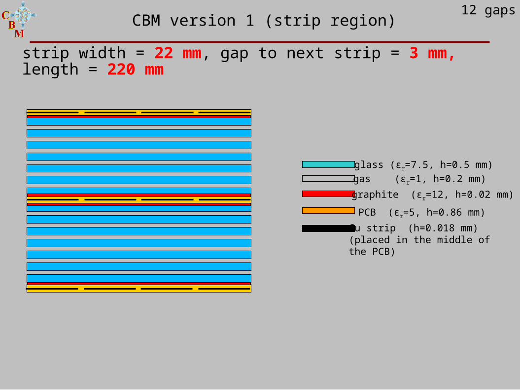
strip width = 22 mm, gap to next strip = 3 mm, length = 220 mm
glass (εr=7.5, h=0.5 mm)
graphite (εr=12, h=0.02 mm)
gas (εr=1, h=0.2 mm)
PCB (εr=5, h=0.86 mm)
Cu strip (h=0.018 mm)(placed in the middle ofthe PCB)
CBM version 1 (strip region)12 gaps
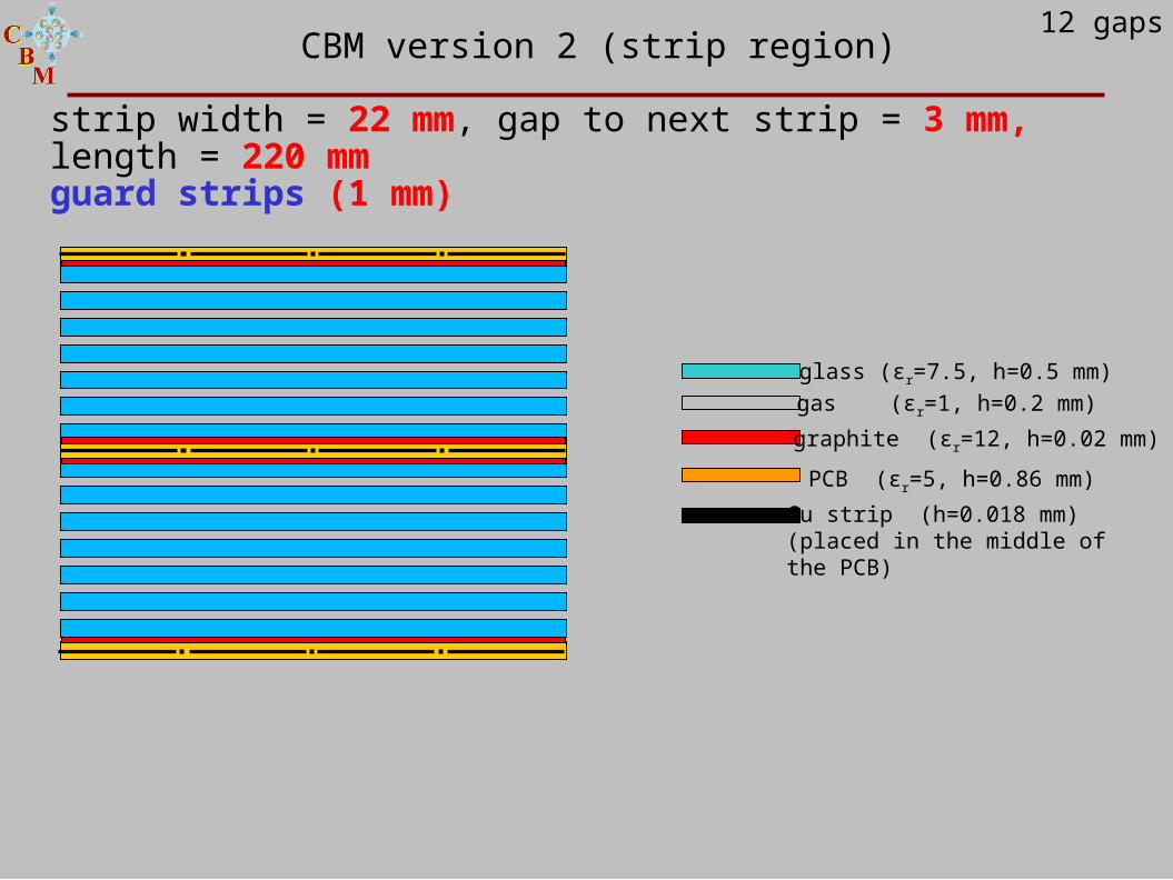
strip width = 22 mm, gap to next strip = 3 mm, length = 220 mmguard strips (1 mm)
glass (εr=7.5, h=0.5 mm)
graphite (εr=12, h=0.02 mm)
gas (εr=1, h=0.2 mm)
PCB (εr=5, h=0.86 mm)
Cu strip (h=0.018 mm)(placed in the middle ofthe PCB)
CBM version 2 (strip region)12 gaps
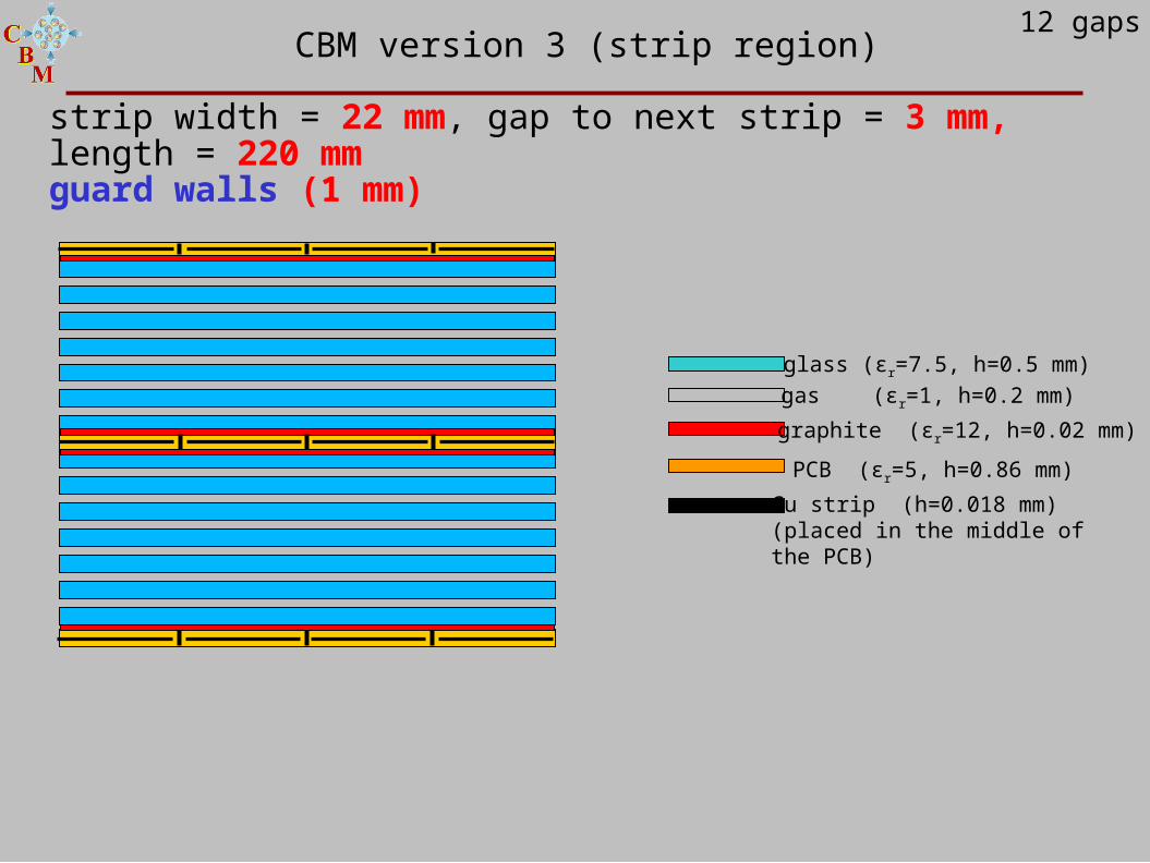
strip width = 22 mm, gap to next strip = 3 mm, length = 220 mmguard walls (1 mm)
glass (εr=7.5, h=0.5 mm)
graphite (εr=12, h=0.02 mm)
gas (εr=1, h=0.2 mm)
PCB (εr=5, h=0.86 mm)
Cu strip (h=0.018 mm)(placed in the middle ofthe PCB)
CBM version 3 (strip region)12 gaps
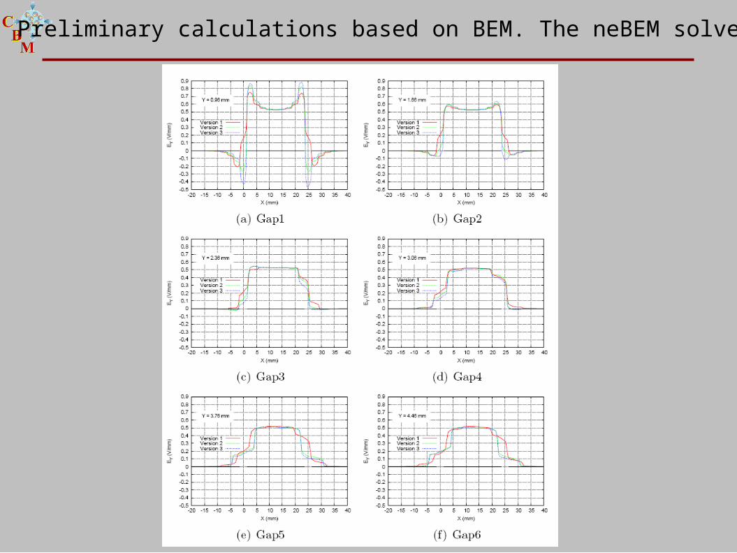
Preliminary calculations based on BEM. The neBEM solver.
4. Propagation.
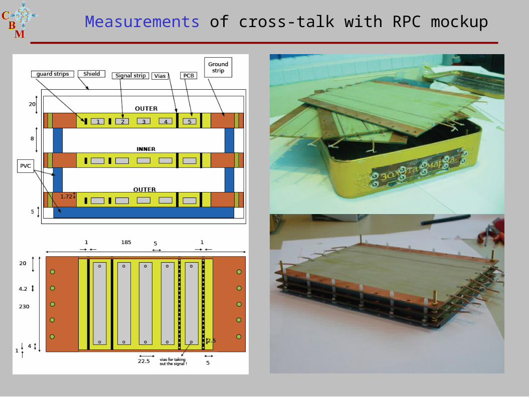
Measurements of cross-talk with RPC mockup
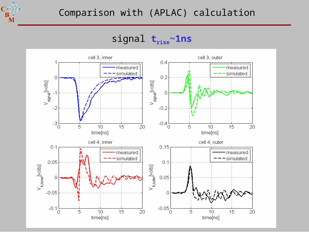
Comparison with (APLAC) calculation
signal trise~1ns
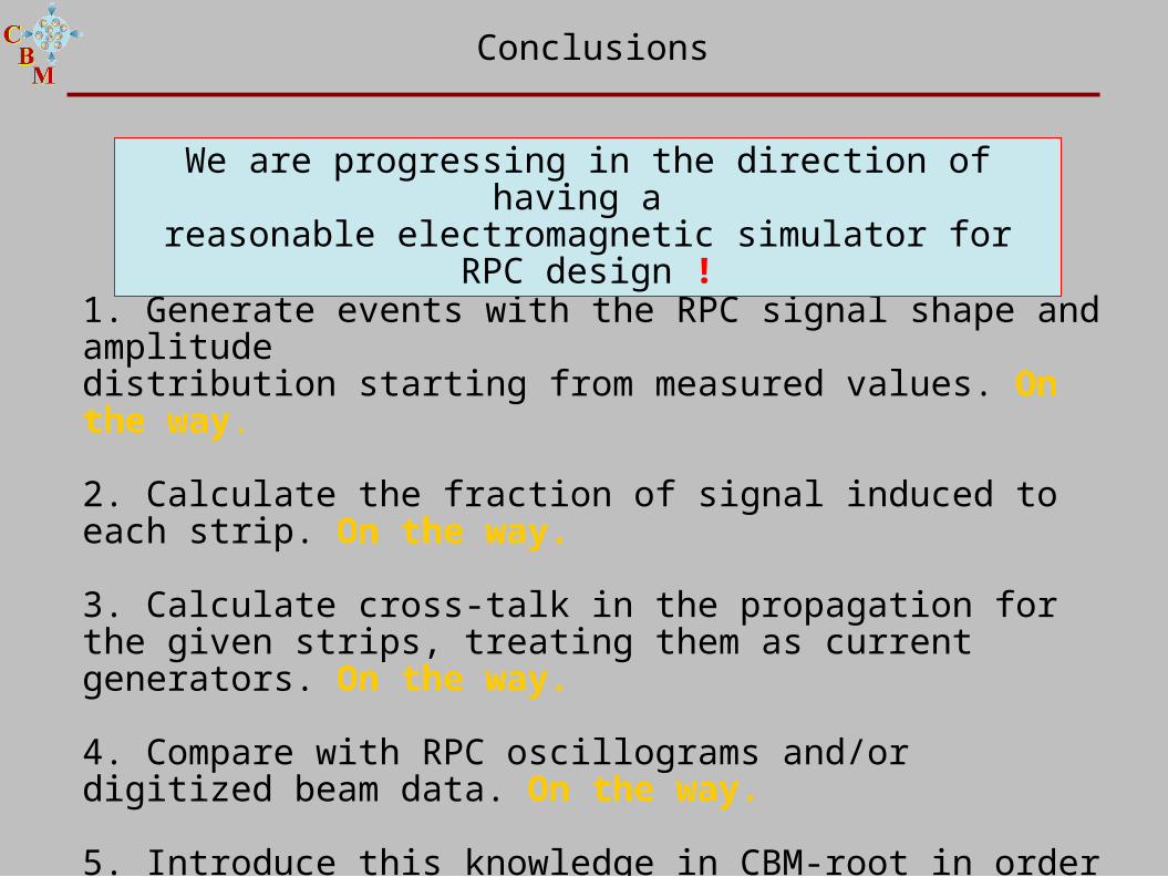
1. Generate events with the RPC signal shape and amplitude distribution starting from measured values. On the way.
2. Calculate the fraction of signal induced to each strip. On the way.
3. Calculate cross-talk in the propagation for the given strips, treating them as current generators. On the way.
4. Compare with RPC oscillograms and/or digitized beam data. On the way.
5. Introduce this knowledge in CBM-root in order to do a meaningful design. To be done.
Conclusions
We are progressing in the direction of having a reasonable electromagnetic simulator for RPC
design !

Appendix
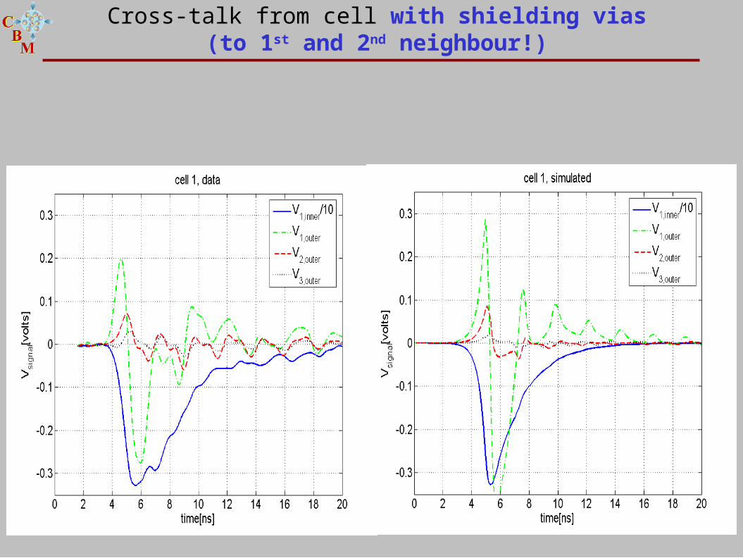
Cross-talk from cell with shielding vias(to 1st and 2nd neighbour!)
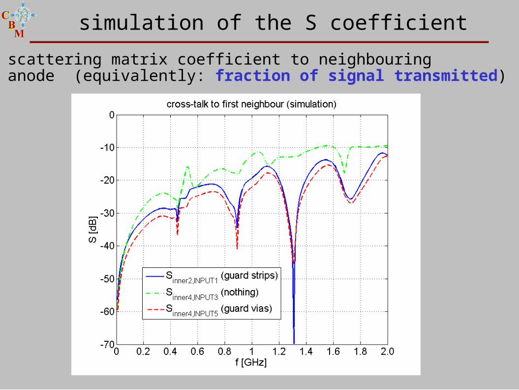
simulation of the S coefficient
scattering matrix coefficient to neighbouring anode (equivalently: fraction of signal transmitted)
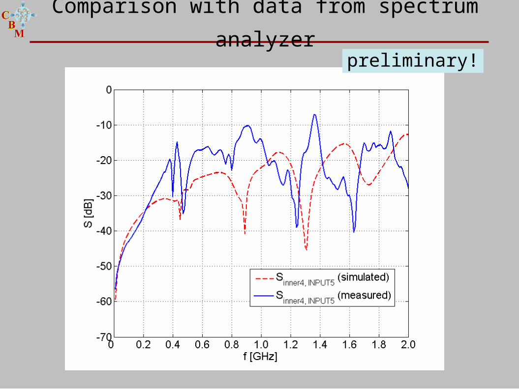
Comparison with data from spectrum analyzer
preliminary!
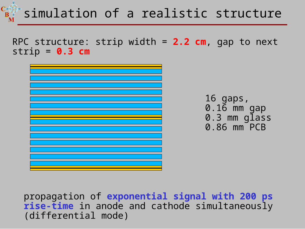
simulation of a realistic structure
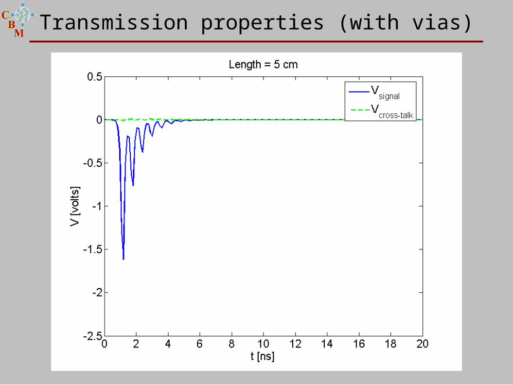
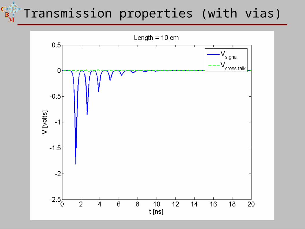
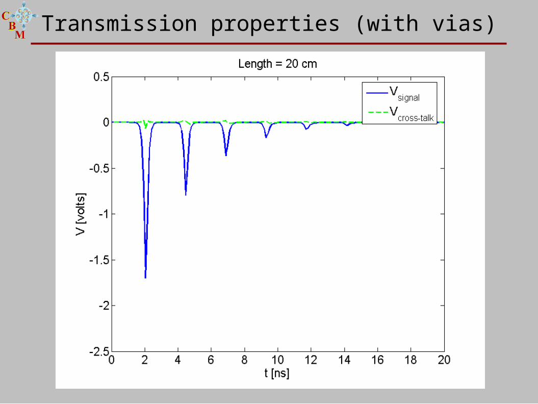
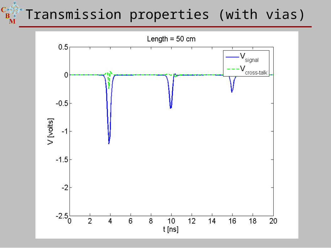
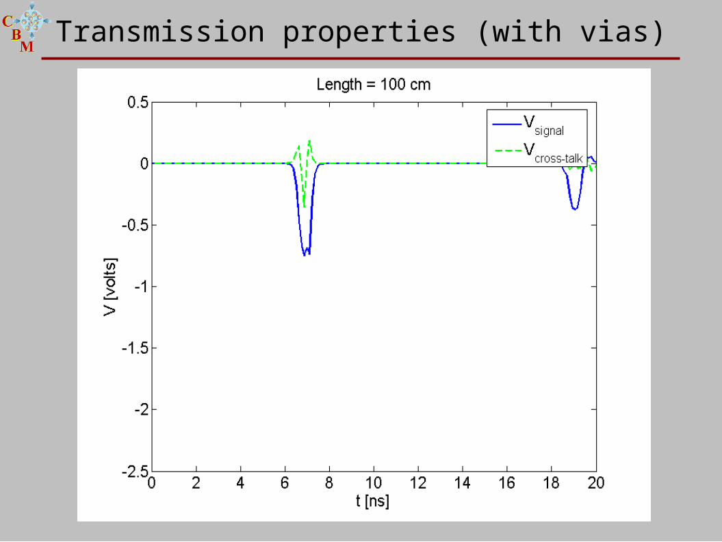
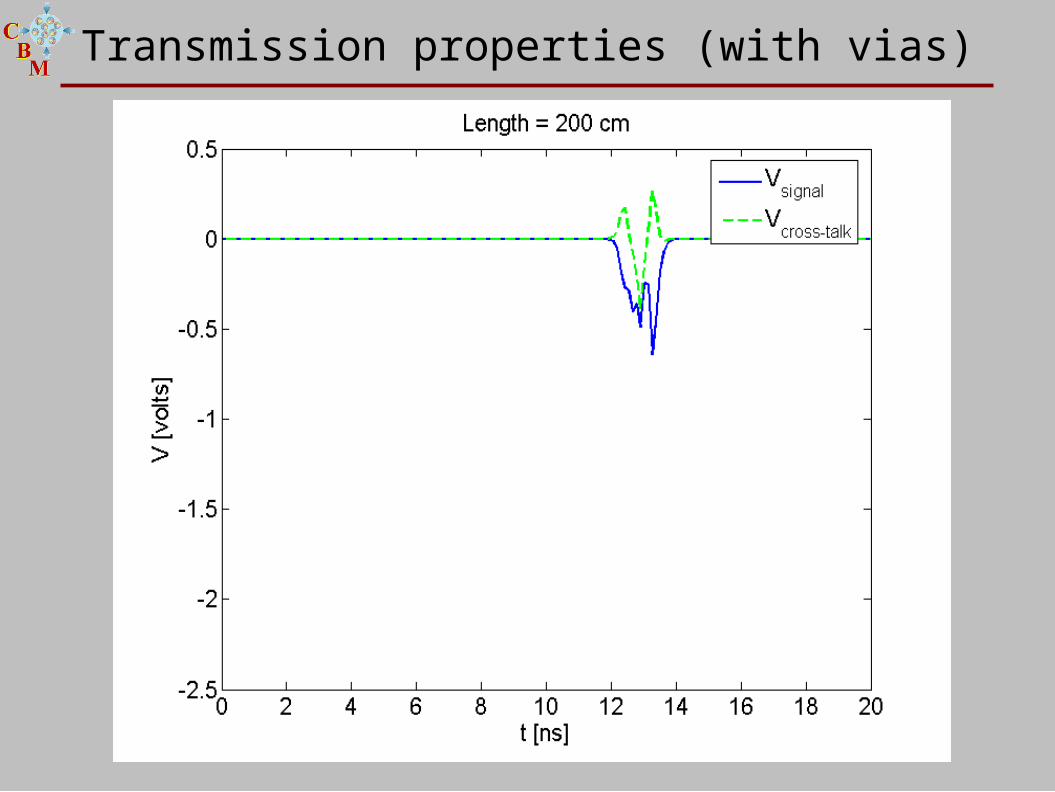
propagation of exponential signal with 200 ps rise-time in anode and cathode simultaneously (differential mode)
RPC structure: strip width = 2.2 cm, gap to next strip = 0.3 cm
16 gaps,0.16 mm gap0.3 mm glass0.86 mm PCB
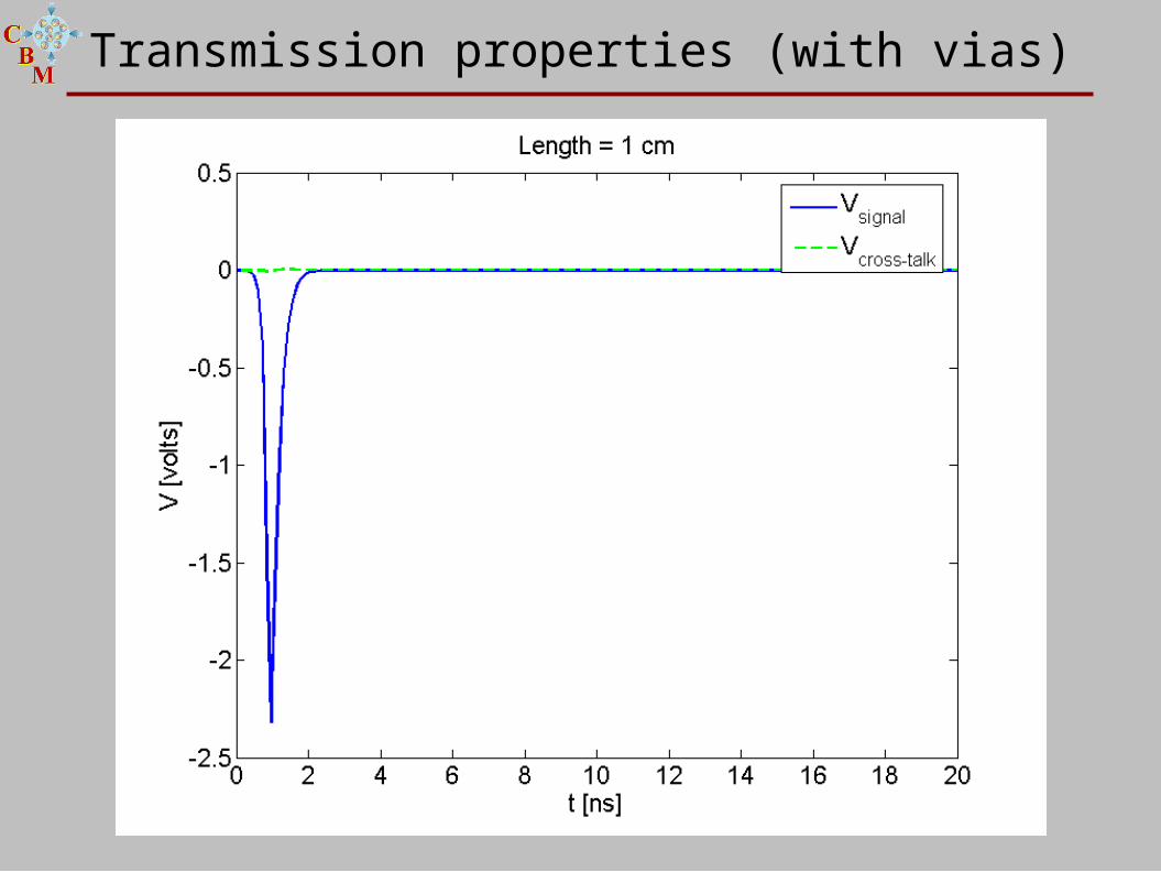
Transmission properties (with vias)
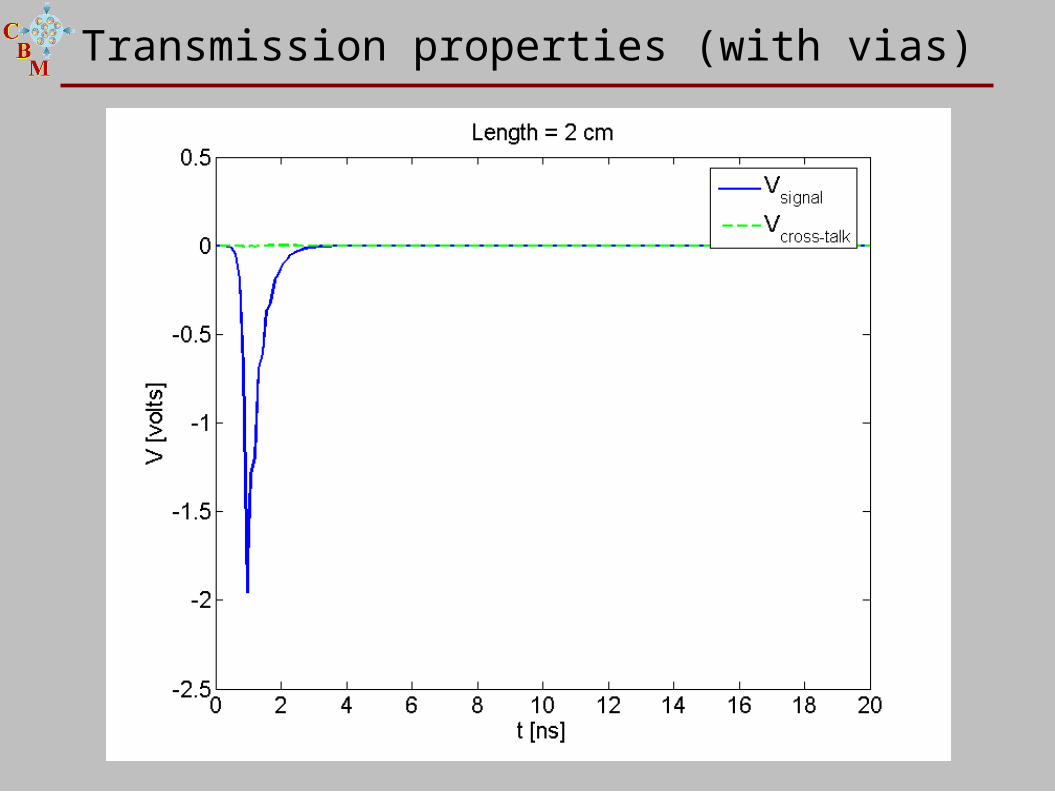
Transmission properties (with vias)
Transmission properties (with vias)
Transmission properties (with vias)
Transmission properties (with vias)
Transmission properties (with vias)
Transmission properties (with vias)
Transmission properties (with vias)
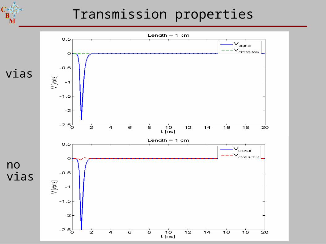
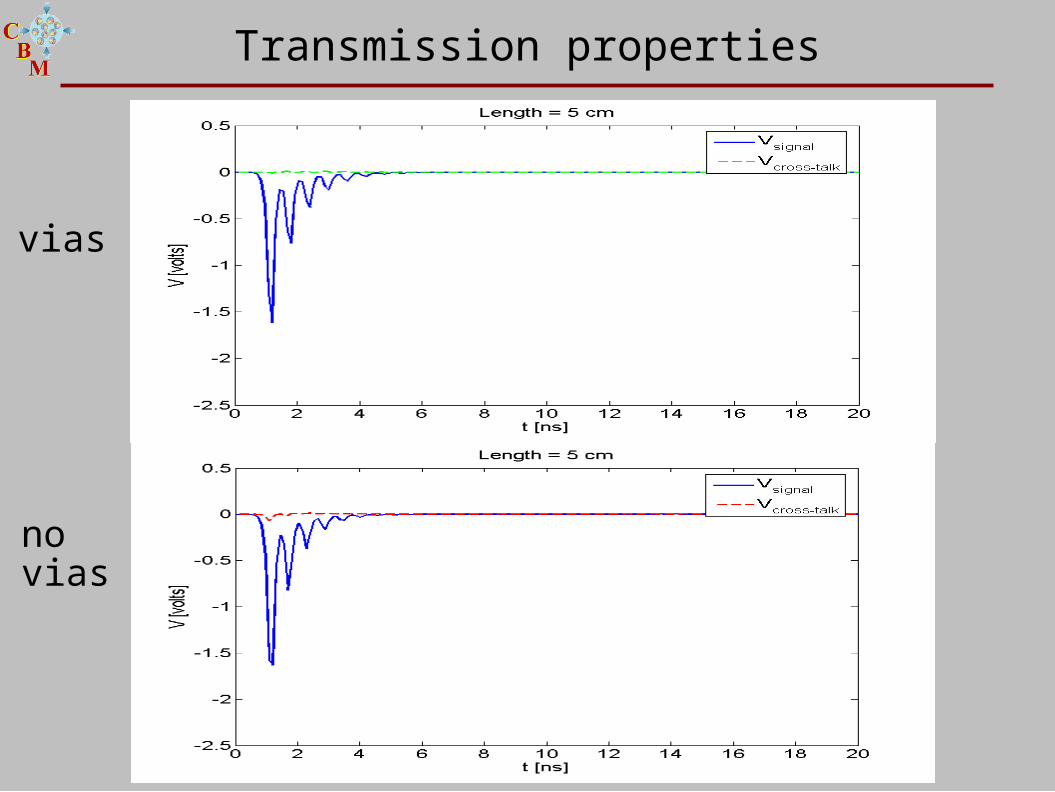
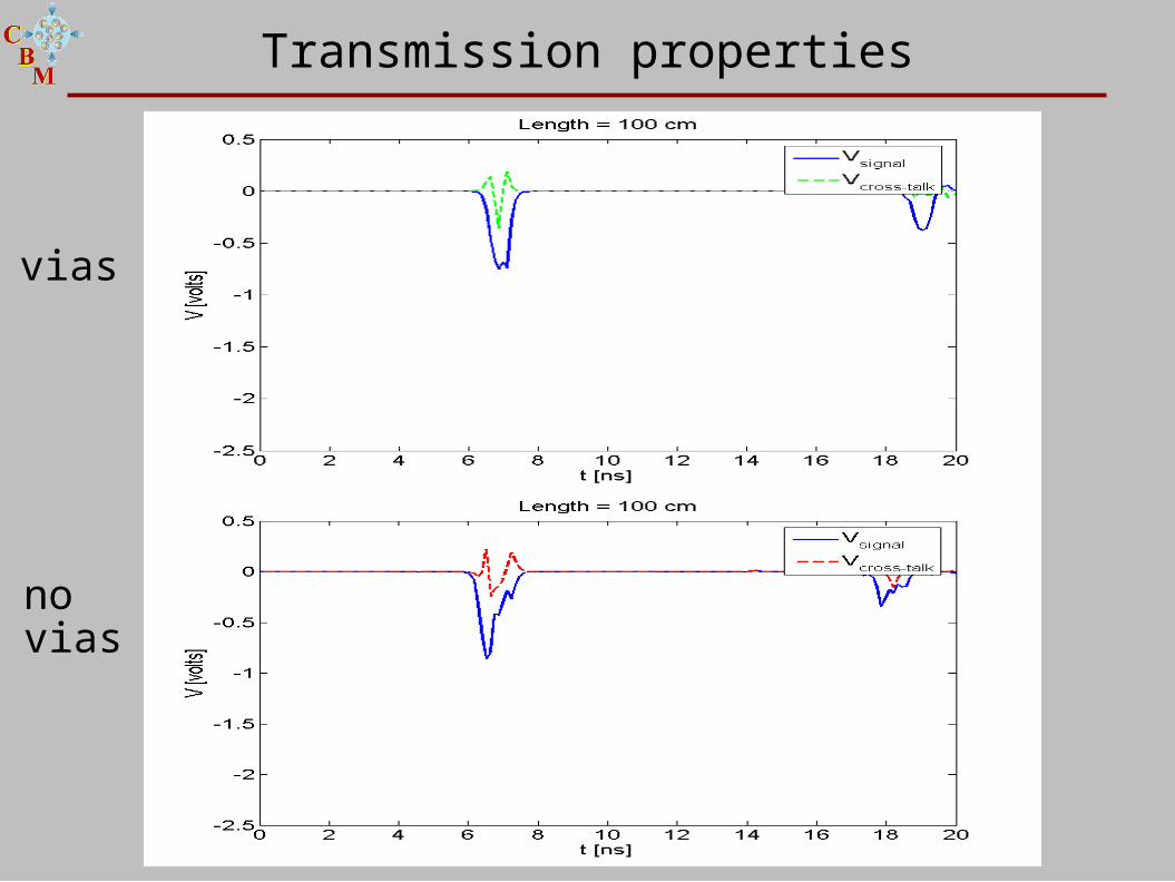
Transmission properties
vias
no vias
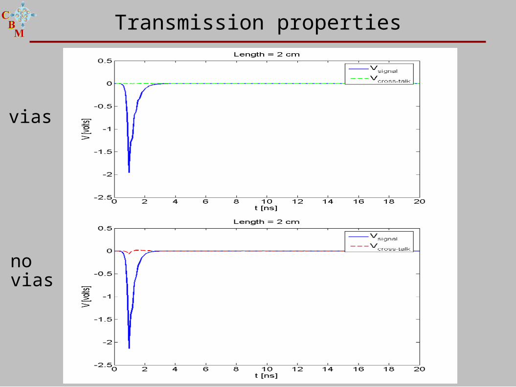
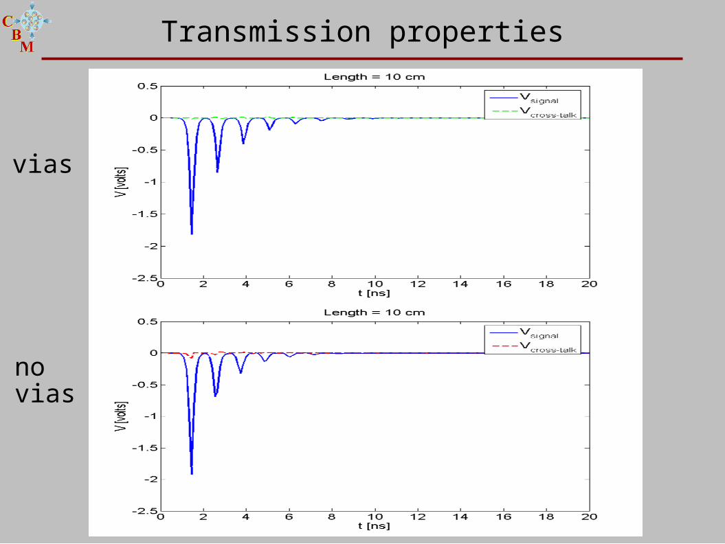
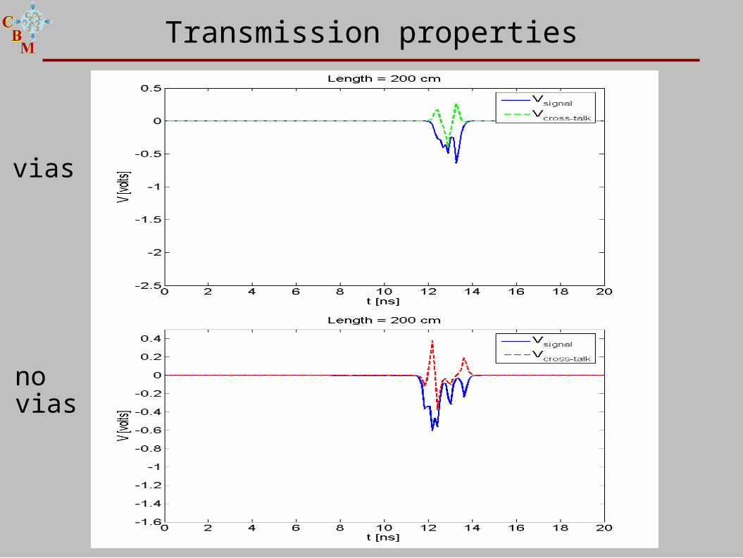
Transmission properties
vias
no vias
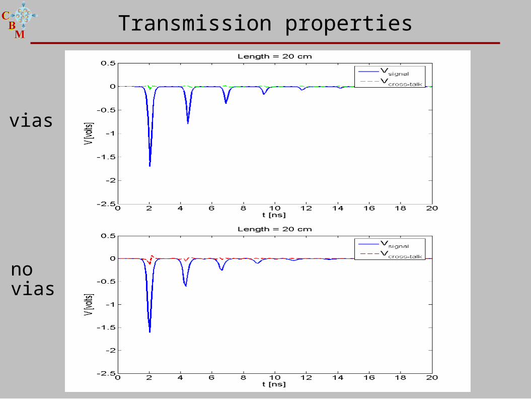
Transmission properties
vias
no vias
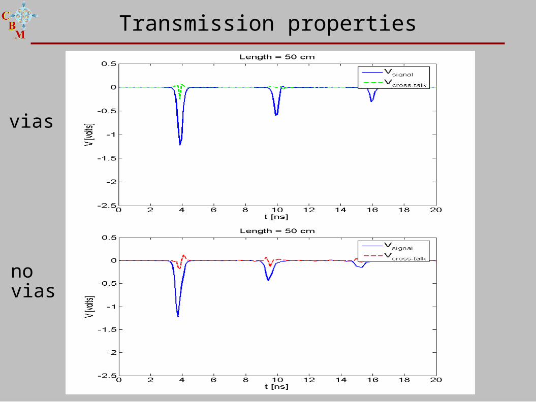
Transmission properties
vias
no vias
Transmission properties
vias
no vias
Transmission properties
vias
no vias
Transmission properties
vias
no vias
Transmission properties
vias
no vias

all in a nut-shell
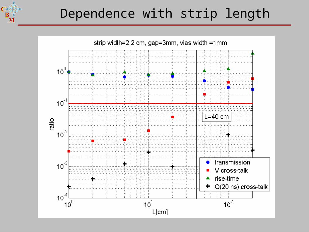
Dependence with strip length
Dependence with strip length
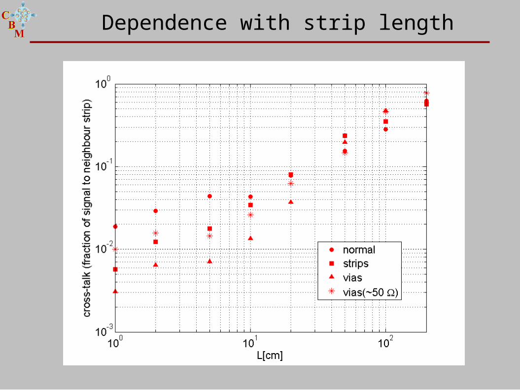
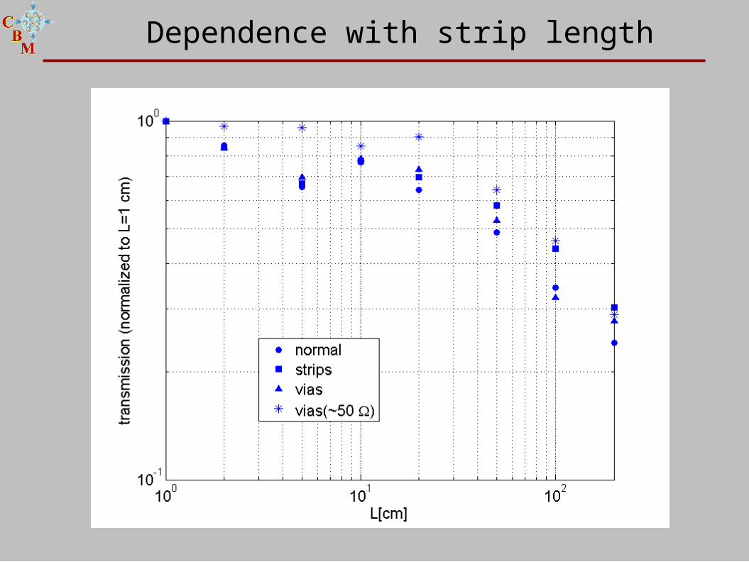
Dependence with strip length
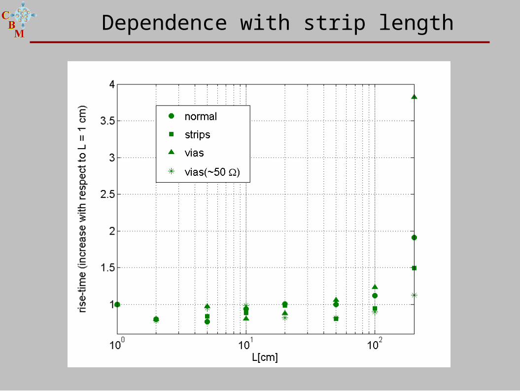
Dependence with strip length