Embed Size (px)
Citation preview

INTERNATIONAL JOURNAL OF OPTIMIZATION IN CIVIL ENGINEERING
Int. J. Optim. Civil Eng., 2016; 6(1):135-158
CRITICAL INCIDENT ANGLE FOR THE MINIMUM COST
DESIGN OF LOW, MID AND HIGH-RISE STEEL AND
REINFORCED CONCRETE-COMPOSITE BUILDINGS
Ch.Ch. Mitropoulou1 and N.D. Lagaros1,2*, † 1Institute of Structural Analysis & Antiseismic Research, Department of Structural
Engineering, School of Civil Engineering, National Technical University of Athens, 9,
Heroon Polytechniou Str., Zografou Campus, GR-15780 Athens, Greece 2iOPTI, Consulting and Design Optimization Group, École Polytechnique, X-Up, Avenue
Coriolis, 91128 Palaiseau Cedex, Paris, France
ABSTRACT
One of the main tasks of engineers is to design structural systems light and economic as
possible, yet resistant enough to withstand all possible loads arising during their service life
and to absorb the induced seismic energy in a controlled and predictable fashion. The
traditional trial-and-error design approach is not capable to determine an economical design
satisfying also the code requirements. Structural design optimization, on the other hand,
provides a numerical procedure that can replace the traditional design approach with an
automated one. The objective of this work is to propose a performance-based seismic design
procedure, formulated as a structural design optimization problem, for designing steel and
steel-concrete composite buildings subject to interstorey drift limitations. In particular a
straightforward design procedure is proposed where the influence on both record and
incident angle is considered. For this purpose six test examples are considered, in particular
three steel and three steel-concrete composite buildings are optimally designed for minimum
initial cost.
Kewords: performance-based design; fibre modelling; steel and steel-reinforced concrete
composite buildings; incident angle; metaheuristic optimization.
Received: 20 August 2015; Accepted: 3 October 2015
*Corresponding author: School of Civil Engineering, National Technical University of Athens, 9, Heroon
Polytechniou Str., Zografou Campus, GR-15780 Athens, Greece †E-mail address: [email protected] (N.D. Lagaros)

Ch.Ch. Mitropoulou and N.D. Lagaros
136
1. INTRODUCTION
The modern approach to structural design for the case of seismic or wind loading is based on
the principal that a structure should meet performance objectives for a number of hazard
levels. This approach constitutes the performance-based design (PBD) concept, which has
been introduced in order to increase the safety against natural hazards. According to PBD
the structures should be able to resist all loading conditions arising during their service life
in a quantifiable manner and to present levels of desired possible damage. The current state
of practice in performance-based engineering for the case of earthquake loading can be
found in US guidelines such as ASCE-41 [1], FEMA-445 [2] and ATC-58 [3]. Towards this
goal, these guidelines suggest higher-order analysis procedures for the design and
assessment in seismic prone areas.
Among others [4,5], incremental dynamic analysis (IDA) [6] is considered as an analysis
procedure for obtaining good estimates of the structural performance in the case of
earthquake hazard and it is considered as an appropriate method to be incorporated into the
optimization procedure. In view of the complexity and the computational effort required by
the 3D models, that are employed to represent real buildings, simplified 2D structural
simulations are used during the design procedure, therefore it is not possible to employ a 2D
simulation since the bidirectional orthogonal shaking effects should be taken into account. In
studies by the authors [7,8] multicomponent incremental dynamic analysis (MIDA) has been
proposed. Multicomponent incremental dynamic analysis (MIDA) is performed in a similar
way that the 2D implementation of IDA does, i.e. a suit of records is selected and for each
record an MIDA representative curve is derived. The 50% fractile MIDA curve is then
calculated using the representative curves of all the records. Selecting the IDA
representative curve in its 2D implementation is, in most cases, a straightforward procedure.
On the other hand in its 3D implementation is not an easy task, since the incident angle
selected for applying the two components of the records might influence considerably the
product of MIDA [7,8].
A highly efficient design framework can be offered by structural optimisation taking
advantage of the benefits offered by nonlinear, static or dynamic analysis methods. PBD
formulated as a structural optimisation problem is a topic of growing interest and has been
the subject of extensive research over the last years. Advancements in structural
optimisation have made possible the move from traditional trial-and-error design procedures
towards fully automated approaches based on a structural optimisation search-engine. This is
mostly attributed to the rapid development of metaheuristic optimization methods, which are
capable of handling complicated design optimization problems.
In recent years, steel-reinforced concrete composite buildings have been experiencing
increased use worldwide. This is because reinforced concrete (RC) is not expensive and RC
members are stiff; on the other hand steel members are strong, lightweight and easy to
assemble. In composite columns two systems are commonly used: (i) steel reinforced
concrete members, where a steel section is encased in concrete and (ii) concrete filled tubes.
In many cases, the choice of either of the two systems is based on their excellent resistance
to seismic loading. The objective of this work is the formulation of a performance-based
optimum design framework for designing steel and steel-RC composite moment resisting
building structures subject to interstorey drift limitations with reference to their initial cost

CRITICAL INCIDENT ANGLE FOR THE MINIMUM COST DESIGN OF LOW ...
137
where the influence of the seismic incident angle is examined by means of MIDA. In
particular a straightforward design procedure is proposed where the influence on both record
and incident angle is considered. For this purpose low, mid and high-rise steel and steel-RC
composite 3D buildings are considered. More specifically six test examples are considered,
in particular three steel and three steel-concrete composite buildings are optimally designed
with minimum initial cost.
2. SURVEY ON PERFORMANCE-BASED DESIGN OPTIMIZATION
A number of studies have been published in the past where the concept of performance-
based design optimization was studied. Among others, Fuyama et al. [9] presented a
computer-based design methodology for the control of interstorey drift caused by equivalent
static earthquake loads in tall moment resisting steel frame structures. Beck et al. [10]
presented a general framework for multi-criteria optimal design, which is well suited for
performance-based design of structural systems operating in an uncertain dynamic
environment. Ganzerli et al. [11] proposed a performance-based optimization procedure of
reinforced concrete (RC) frames using a mathematical optimizer. Esteva et al. [12] presented
a life-cycle formulation for the determination of optimum values of the mechanical
properties of a structural system exposed to seismic risk. The resulting values were used for
the establishment of performance-acceptance criteria for seismic design. Khajehpour and
Grierson [13] investigated the trade-off between life-cycle profitability and load-path safety
for a high-rise office-building project, while they proposed alternative building layouts with
increased safety using a multi-criterion genetic algorithm (GA). Li and Cheng [14]
introduced a damage reduction based technique in the framework of structural optimization
and showed that the proposed design concept leads to designs with better seismic
performance in terms of both life-cycle cost and maximum interstorey drift criteria. Chan
and Zou [15] presented an effective optimization technique for the elastic and inelastic drift
performance design of reinforced concrete buildings under response spectrum loading and
pushover loading. Liu et al. [16] proposed a GA-based multi-objective structural
optimization procedure for steel frames considering four objective functions; weight,
maximum interstorey drift for two performance levels, and design complexity criteria. Chan
and Wang [17] developed an optimality criteria based algorithm for solving the minimum
weight design problem subject to multiple drift constraints and member sizing requirements.
Fragiadakis et al. [18] proposed a performance-based optimization procedure for steel
moment-resisting frames in the probabilistic framework of FEMA-350 [19]. Fragiadakis et
al. [20] proposed a new methodology for the performance-based optimum design of steel
structures subjected to seismic loading considering inelastic behaviour, while the importance
of considering life-cycle cost as an additional objective to the initial structural cost objective
function in the context of multi-objective optimization was also investigated. Foley et al.
[21] presented an overview of a state-of-the-art model-code performance-based design
methodology and implemented this design procedure into multiple-objective optimization
problems for single and multi-storey structural steel frameworks with fully and partially
restrained connections. Lagaros and Papadrakakis [22] evaluated the European seismic
design code when used for the design of 3D reinforced concrete buildings, versus a PBD
Ch.Ch. Mitropoulou and N.D. Lagaros
138
procedure, in the framework of a multi-objective optimization concept. Rojas et al. [23] used
GA to solve this complex optimization problem where confidence levels were incorporated
into the fitness function along with initial construction cost in a series of optimal design
scenarios. A fully automated design methodology based on nonlinear response history
analysis was proposed by Fragiadakis and Papadrakakis [24] for the optimum seismic design
of reinforced concrete structures. Mitropoulou et al. [25] assessed the European seismic
design codes and in particular of EC2 and EC8 with respect to the recommended behaviour
factor q into an optimization framework. Lagaros et al. [26] proposed a PBD methodology
for the design of reinforced concrete buildings, taking into account the influence of infill
walls, while two variants of the PBD framework are examined relying either on the non-
linear static or on the non-linear dynamic analysis procedure. Kaveh et al. [27] presented a
performance-based optimal seismic design of frame structures using the ant colony
optimization method. The current state-of-practice static pushover methods as suggested in
the provisions of European and American regulations are implemented in a comparative
study by Lagaros and Fragiadakis [28], in a performance-based design optimization
framework. Esteva et al. [29] presented an overview of life-cycle optimisation in the
establishment of reliability and performance-based seismic design requirements for multi-
storey systems. Al-Ansari and Senouci [30] presented a drift design structural model for the
design optimization of high-rise buildings in seismic zones. Fragiadakis and Lagaros [31]
presented a general PBD optimization framework for steel structures; while in Mitropoulou
et al. [32] presented a multiobjective life-cycle optimisation problem examining the
parameters that affect the LCCA procedure. Lagaros and Magoula [33] employed life-cycle
cost analysis (LCCA) for assessing the optimum designs obtained for steel and steel-
concrete composite design practices. Kaveh et al. [34] dealt with design optimization of real
size 3D steel structures under seismic loading based on response spectral and equivalent
static analyses, investigated also the effect of lateral seismic loading distribution on the
achieved optimum designs.
3. CRITICAL ORIENTATION OF THE SEISMIC INCIDENCE
A structure subjected to the simultaneous action of two orthogonal horizontal ground
accelerations along the directions Ow and Op is illustrated in Fig. 1. The orthogonal system
Oxyz defines the reference axes of the structure (structural axes). The angle defined with a
counter clockwise rotation of the structural axis Ox to coincide with the ground motion axis
Ow is called as incident angle of the record.
According to Penzien and Watabe [35] the orthogonal directions of a ground motion can
be considered uncorrelated in the principal directions of the structure. This finding was the
basis for many researchers in order to define the orientation that yields the maximum
response when the response spectrum dynamic analysis was applied. In the work by Wilson
et al. [36] it was proposed an alternative code approved method that results in structural
designs having equal resistance to seismic motions from all directions. Lopez and Torres
[37] proposed a simple method, which can be employed by the seismic codes to determine
the critical angle of seismic incidence and the corresponding peak response of structures
subjected to two horizontal components applied along any arbitrary directions and to the

CRITICAL INCIDENT ANGLE FOR THE MINIMUM COST DESIGN OF LOW ...
139
vertical component of earthquake ground motion. The CQC3 response spectrum rule for
combining the contributions from three orthogonal components of ground motion to the
maximum value of a response quantity is presented in the work by Menun and Der
Kiureghian [38]. In two works by Lopez et al. [39,40] it is proposed an explicit formula,
convenient for code applications, in order to calculate the critical value of the structural
response to the two principal horizontal components acting along any incident angle with
respect to the structural axes, and the vertical component of ground motion. In two works by
Menun and Der Kiureghian [41,42] a response spectrum based procedure for predicting the
envelope that bounds two or more responses in a linear structure is developed. In the work
by Anastassiadis et al. [43] a seismic design procedure for structures is proposed based on
the model of Penzien and Watabe [35].
Figure 1. Definition of the incident angle α
To the author’s knowledge there are only few studies reported in the literature where the
case of the critical incident angle is examined when time history analysis is employed. In
these studies it was found that it is not an easy task to define the critical angle, while it is
record dependent when nonlinear structural behaviour is encountered. In the work by
MacRae and Mattheis [44] it is shown the ability of the 30% SRSS rule and the sum of
absolute values methods to assess building drifts for bidirectional shaking effects, while it is
also shown that the response is dependent on the reference axes chosen. MacRae and
Tagawa [45] have found that design level shaking caused the structure to exceed story yield
drifts in both directions simultaneously and significant column yielding occurred above the
base. Shaking a structure in the direction orthogonal to the main shaking direction increased
drifts in the main shaking direction, indicating that 2D analyses would not estimate the 3D
response well. Ghersi and Rossi [46] examined the influence of bi-directional seismic
excitations on the inelastic behaviour of in-plan irregular systems having one symmetry axis
where it was found that in most cases the adoption of Eurocode 8 provisions to combine the
effects of the two seismic components allows the limitation of the orthogonal elements
ductility demand. In the work by Athanatopoulou [47] analytical formulae were developed
for determining the critical incident angle and the corresponding maximum value of a
response quantity of structures subjected to three seismic correlated components when linear
behaviour is considered. The analyses results have shown that, for the earthquake records
used, the critical value of a response quantity can be up to 80% larger than the usual

Ch.Ch. Mitropoulou and N.D. Lagaros
140
response produced when the seismic components are applied along the structural axes.
Rigato and Medina [48] studied a number of symmetrical and asymmetrical structures
having fundamental periods ranging from 0.2 to 2.0 seconds where it was examined the
influence that the incident angle of the ground motion has on several engineering demand
parameters. Lagaros [8] assessed four 3D reinforced concrete buildings with reference to life
cycle cost calculated based on MIDA and the significance of considering randomness on
both record and incident angle is demonstrated.
4. PERFORMANCE-BASED SEISMIC DESIGN
The majority of the seismic design codes belong to the category of the prescriptive design
codes that take into consideration site selection and development of the conceptual,
preliminary and final design stages. According to a prescriptive design code the strength of
the structure is evaluated at one limit state, between life-safety and near collapse, using a
response spectrum-based loading corresponding to one or two design earthquakes (e.g.
Eurocode 8, 2004). In addition, the serviceability limit state is usually checked in order to
ensure that the structure will not deflect or vibrate excessively. On the other hand,
performance-based design implies the design, evaluation, construction and maintenance of
engineering facilities in order to meet the objectives set by the society and owners/users of a
facility [49]. In the case of seismic loading, the aim is to build structures having a
predictable and reliable performance, or in other words, to be able to resist earthquakes with
quantifiable confidence. Therefore, the modern conceptual approach of seismic structural
design is that the structures should meet performance-based objectives for a number of
different hazard levels ranging from earthquakes with a small intensity and with a small
return period, to more destructive events with large return periods. The current state of
practice in performance-based earthquake engineering is defined by US guidelines [1-3].
These guidelines do not differ conceptually and introduce procedures that can be considered
as the first significant diversification from prescriptive building design codes. For the PBD
procedure, prior to any structural analysis, the column to beam strength ratio is calculated
and is examined whether the sections chosen are of class 1, as Eurocode 3 [50] suggests.
Class 1 cross-sections are those, which can form a plastic hinge with the rotation capacity
required from plastic analysis without reduction of the resistance. The column to beam
strength ratio is calculated as:
1 20M pl ,column
M pl ,beam
.
(1)
where ΣMpl,column and ΣMpl,beam is the sum of the design values of plastic moment resistances
of the structural members at each joint.
The PBD procedure consists of the following steps: (i) All Eurocode checks must be
satisfied for the gravity loads; (ii) if the checks of Step (i) are satisfied then NSP is
performed in order to explicitly calculate the demand for the defined intensity levels. The
structural capacity is associated to the maximum interstorey drift values θ, and the

CRITICAL INCIDENT ANGLE FOR THE MINIMUM COST DESIGN OF LOW ...
141
acceptance criteria of Step (ii) are confirmed if satisfied or not in order to accept or revise
the design. The main part in a performance-based seismic design procedure is the definition
of the performance objectives. A performance objective is defined as a given level of
performance for a specific hazard level. In order to assess the structural performance in
terms of strength and deformation capacity globally as well as at the element level a
nonlinear analysis procedure is required. In this work the PBD framework is based on the
nonlinear dynamic procedure (NDP) and in particular MIDA. Three performance levels are
considered and 20 ground motion records are used for each hazard level. For each hazard
level the median response out of the 20 records is used. The characteristics of the records are
provided in Table 1.
Table 1: Characteristics of the group of 20 records
Record/Station R1
(km)
EpiD2
(km)
Recording Angle
log/tran (o)
Duration
(sec)
PGAlog
(g)
PGAtran
(g)
Campbell’s
GEOCODE3
Fault
rupture4
Superstition Hills 1987
(B) (M=6.7)
El Centro Imp. Co Cent 18.5 35.83 000/090 40.00 0.36 0.26 A SS
Wildlife Liquefaction
Array 24.1 29.41 090/360 44.00 0.18 0.21 A SS
Imperial Valley 1979
[23:16], (M=6.5)
Chihuahua 8.4 18.88 012/282 40.00 0.27 0.25 A SS
Compuertas 15.3 24.43 015/285 36.00 0.19 0.15 A SS
Plaster City 31.1 54.26 045/135 18.75 0.042 0.057 A SS
El Centro Array #12 18.85 31.99 140/230 39.00 0.143 0.116 A SS
El Centro Array #13 22.83 35.95 140/230 39.50 0.117 0.139 A SS
San Fernando 1971
(M=6.6)
LA, Hollywood Stor. Lot 25.9 39.49 090/180 28.00 0.21 0.17 A RN
Northridge 1994 (M=6.7)
Leona Valley #2 37.2 51.88 000/090 32.00 0.09 0.06 A RN
LA, Baldwin Hills 29.9 28.20 090/360 40.00 0.24 0.17 C RN
Lake Hughes #1 89.67 93.22 000/090 32.00 0.087 0.077 A RN
LA, Hollywood Stor FF 114.62 118.2 090/360 40.00 0.231 0.358 A RN
LA, Centinela St. 31.53 32.72 155/245 30.00 0.465 0.322 A RN
Loma Prieta 1989 (M=6.9)
Hollister Diff Array 24.8 45.10 165/255 39.64 0.27 0.28 A RO
WAHO 17.5 12.56 000/090 24.96 0.37 0.64 C RO
Halls Valley 30.5 36.31 000/090 39.95 0.13 0.10 B RO
Agnews State Hospital 24.6 40.12 000/090 40.00 0.17 0.16 A RO
Anderson Dam
(Downstream) 4.4 16.67 270/360 39.61 0.244 0.240 B RO
Coyote Lake Dam
(Downstream) 20.8 30.89 195/285 39.95 0.160 0.179 B RO
Hollister - South & Pine 27.93 48.24 000/090 60.00 0.371 0.177 A RO 1Campbell’s R Distance
2Distance from the recording site to epicentre
3Campbell’s site classification: A (Firm Soil), B (Very Firm Soil), C (Soft Rock), D (Firm
Rock), E (Shallow Soils) 4Fault rupture mechanism: SS (Strike Slip), N (Normal), RN (Reverse-Normal), RO
(Reverse-Oblique), NO (Normal- Oblique)

Ch.Ch. Mitropoulou and N.D. Lagaros
142
5. MULTICOMPONENT INCREMENTAL DYNAMIC ANALYSIS USED
FOR DESIGN OF STRUCTURES
In the seismic assessment and design procedures of structures a wide range of seismic
records and more than one performance level should be considered in order to take into
account the uncertainties that the seismic hazard introduces into a performance-based
seismic assessment procedure. The methods integrated into the performance-based
assessment procedures are classified as single and multiple hazard level methods. Multiple-
stripe dynamic analysis (MSDA) and incremental dynamic analysis (IDA) or MIDA are the
most applicable methods [7]. The main objective of these procedures is to define a relation
between the seismic intensity level and the corresponding maximum response quantity of the
structural system. The intensity level and the structural response are described through an
intensity measures (IMs) and an engineering demand parameters (EDPs), respectively. EDP
in some cases it refers also as damage index (DI). MSDA, IDA or MIDA are implemented
through the following steps: (i) Define the nonlinear finite element model required for
performing nonlinear dynamic analyses; (ii) select a suit of natural records or artificial
accelerograms; (iii) select a proper intensity measure and an engineering demand parameter;
(iv) employ an appropriate algorithm for selecting the record scaling factor in order to obtain
the IM-EDP curve.
According to the MIDA framework a set of natural records, each one represented by its
longitudinal and transverse components, are applied to the structure in order to account for
the randomness on the seismic excitation. The difference of the MIDA framework from the
original one component IDA, proposed by Vamvatsikos and Cornell [6], stems from the fact
that for each record a number of MIDA representative curves can be defined depending on
the incident angle selected, while in most cases of the one component variant of IDA only
one IDA representative curve is obtained. MIDA is based on the idea of considering variable
incident angle for each record, through this implementation randomness both on the seismic
excitation and the incident angle are taken into account. In MIDA the relation of IM-EDP is
defined similarly to the one component version of the IDA, i.e. both horizontal components
of each record are scaled to a number of intensity levels to encompass the full range of
structural behaviour from elastic to yielding that continues to spread, finally leading to
global instability.
6. LOWER BOUND STRUCTURAL DESIGN
The ultimate objective of this study is to compare lower-bound designs, or in other words
comparing the designs that satisfy design requirements in the most cost-effective way, i.e.
those with minimum cross section dimensions, member and reinforcement steel quantities.
For this reason, a structural optimization problem is formulated and the designs obtained are
then assessed. The formulation of a structural optimization problem is defined as follows
CRITICAL INCIDENT ANGLE FOR THE MINIMUM COST DESIGN OF LOW ...
143
min ( , )
subject to ( ) 0 =1,...,
( ) 0 =1,...,
IN
SERV
j
PBD
j
C t
g j m
g j k
s
s
s
F s
(2)
where s represents the design vector with the cross-section dimensions of all columns and
beams, F is the feasible region where all the serviceability and performance-based constraint
functions (gSERV and gPB) are satisfied, while the objective function considered is the initial
cost CIN of the design, which is related to material cost, which includes structural steel,
concrete, steel reinforcement, construction labour costs and the cost of the non-structural
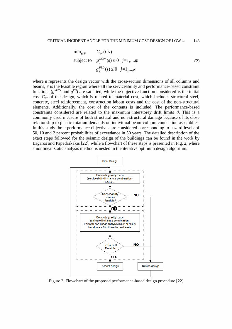
elements. Additionally, the cost of the contents is included. The performance-based
constraints considered are related to the maximum interstorey drift limits θ. This is a
commonly used measure of both structural and non-structural damage because of its close
relationship to plastic rotation demands on individual beam-column connection assemblies.
In this study three performance objectives are considered corresponding to hazard levels of
50, 10 and 2 percent probabilities of exceedance in 50 years. The detailed description of the
exact steps followed for the seismic design of the buildings can be found in the work by
Lagaros and Papadrakakis [22], while a flowchart of these steps is presented in Fig. 2, where
a nonlinear static analysis method is nested in the iterative optimum design algorithm.
Figure 2. Flowchart of the proposed performance-based design procedure [22]

Ch.Ch. Mitropoulou and N.D. Lagaros
144
For the solution of the optimization problem the differential evolution method (DE), is
employed. DE represents a direct search method which utilizes a population of NP
parameter vectors si,g (i=1,..,NP) for each generation g. DE generates new vectors by adding
the weighted difference vector between two population members to a third member. If the
resulting vector corresponds to a better objective function value than a population member,
the newly generated vector replaces this member. The comparison is performed between the
newly generated vector and all the members of the population excluding the three ones used
for its generation. Furthermore, the best parameter vector sbest,g is evaluated in every
generation in order to keep track of the progress achieved during the optimization process.
Several variants of DE have been proposed so far, but the two most widely used are the
following.
According to the variant implemented in this study, a donor vector vi,g+1 is generated first
according to:
1 2 3, 1 , , ,( - ) i g r g r g r gFv s s s
(3)
Before the computation of the ith parameter vector si,g+1. This step is equivalent to the mutation operator step of genetic algorithms or evolution strategies. The integers r1, r2 and r3 are chosen randomly from the interval [1, NP] while i r1, r2 and r3. F is a real constant value, called mutation factor, which controls the amplification of the differential variation
2 3, ,( - )r g r gs s and is defined in the range [0,2]. In the next step the crossover operator is applied by generating the trial vector ui,g+1 = [u1,i,g+1,u2,i,g+1,…,uD,i,g+1]
T which is defined from the elements of the vector si,g and the elements of the donor vector vi,g+1 whose elements enter the trial vector with probability CR as follows:
, , 1 ,
, , 1
, , ,
rand or
rand or
1,2,..., and 1,2,...,
j i g j i rand
j i g
j i g j i rand
v if CR j Iu
if CR j I
i NP j n
s
(4)
where , [0,1],j i randrand U I is a random integer from [1,2,...,n] that ensures that , 1 ,i g i g sv .
The last step of the generation procedure is the implementation of the selection operator where the vector si,g, is compared to the trial vector ui,g+1:
, 1 , 1 ,
, 1
,
if ( ) ( )
otherwise
1,2,...,
i g i g i g
i g
i g
f f
i NP
u u ss
s
(5)
7. MODELLING AND FINITE ELEMENT ANALYSIS
Nonlinear static or dynamic analysis needs a detailed simulation of the structure in the
regions where inelastic deformations are expected to develop. Either the plastic-hinge or the

CRITICAL INCIDENT ANGLE FOR THE MINIMUM COST DESIGN OF LOW ...
145
fibre approach can be adopted for this cause. Given that the plastic hinge approach has
limitations in terms of accuracy fibre beam-column elements are preferable. According to
the fibre approach, every beam-column element has a number of integration sections, each
divided into fibres. Each fibre in the section can be assigned concrete, structural steel, or
reinforcing bar material properties (see Fig. 3 for the case of a composite column). The
sections are located either at the centre of the element or at its Gaussian integration points.
The main advantage of the fibre approach is that every fibre has a simple uniaxial material
model allowing an easy and efficient implementation of the inelastic behaviour. This
approach is considered to be suitable for inelastic beam-column elements under dynamic
loading and provides a reliable solution compared to other formulations. However, it results
to higher computational demands in terms of memory storage and CPU time. When a
displacement-based formulation is adopted the discretization should be adaptive with a
dense mesh at the joints and a single elastic element for the remaining part of the member.
On the other hand, force-based fibre elements allow modelling a member with a single
beam-column element. All the frames are assumed to have rigid connections and fixed
supports. In the numerical test examples section that follows, all analyses have been
performed using the OpenSEES [51] platform and each member is modelled with force-
based beam-column elements. A bilinear material model with pure kinematic hardening is
adopted for the steel fibres, while geometric nonlinearity is explicitly taken into
consideration. For the simulation of the concrete fibres the modified Kent-Park [52] model is
employed while the bracing members are modelled using an inelastic element with pinned
ends [53].
Figure 3. Fibre discretization of a composite section
highly confined concrete
moderately confined
concrete
unconfined concrete
longitudinal
reinforcing steel
transverse
reinforcing steelstructural steel
Ch.Ch. Mitropoulou and N.D. Lagaros
146
8. NUMERICAL EXAMPLES
In this work, three steel and three steel-RC composite 3D moment resisting framed buildings
have been considered in order to study the problem of performance-based design
optimization. The first group of buildings corresponds to steel buildings with two, four and
eight storeys; while the second one corresponds to steel-RC composite buildings also with
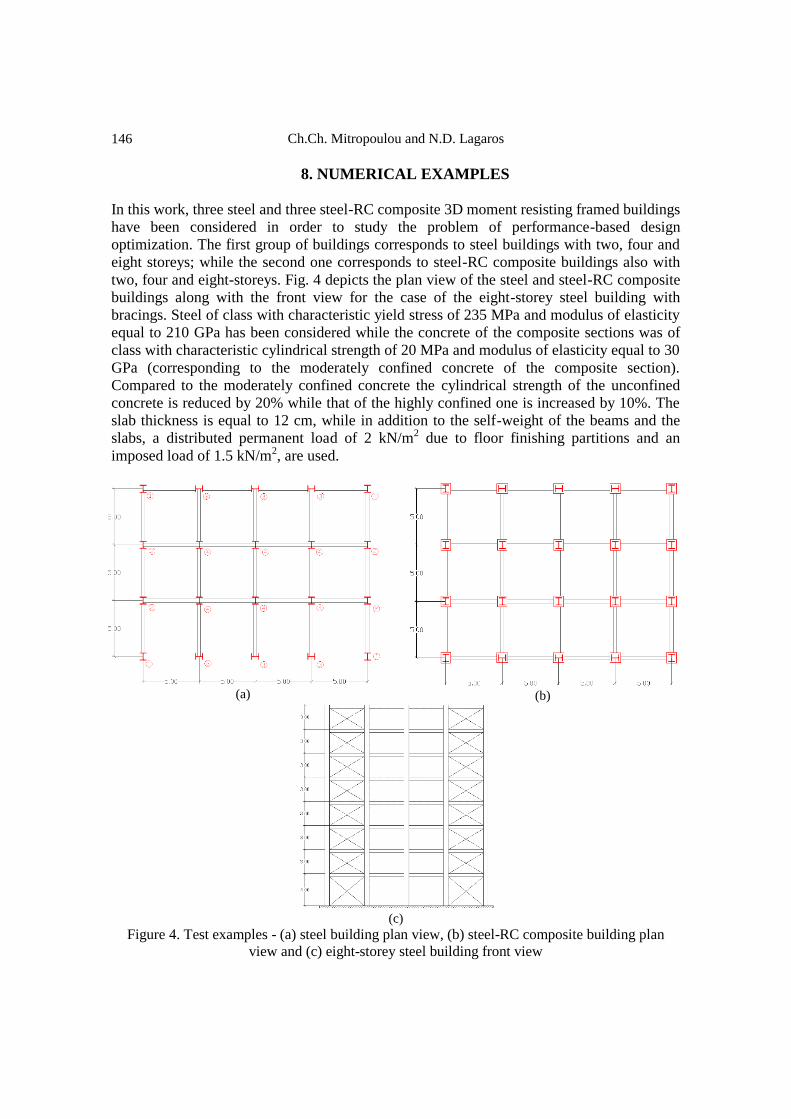
two, four and eight-storeys. Fig. 4 depicts the plan view of the steel and steel-RC composite
buildings along with the front view for the case of the eight-storey steel building with
bracings. Steel of class with characteristic yield stress of 235 MPa and modulus of elasticity
equal to 210 GPa has been considered while the concrete of the composite sections was of
class with characteristic cylindrical strength of 20 MPa and modulus of elasticity equal to 30
GPa (corresponding to the moderately confined concrete of the composite section).
Compared to the moderately confined concrete the cylindrical strength of the unconfined
concrete is reduced by 20% while that of the highly confined one is increased by 10%. The
slab thickness is equal to 12 cm, while in addition to the self-weight of the beams and the
slabs, a distributed permanent load of 2 kN/m2 due to floor finishing partitions and an
imposed load of 1.5 kN/m2, are used.
(a)
(b)
(c)
Figure 4. Test examples - (a) steel building plan view, (b) steel-RC composite building plan
view and (c) eight-storey steel building front view

CRITICAL INCIDENT ANGLE FOR THE MINIMUM COST DESIGN OF LOW ...
147
Two parts compose the numerical investigation. In the first part, in order to examine the
influence of the incident angle on the seismic response of the structure, three records have
been selected at random and are applied to steel test examples. The three records considered
are the one recorded during the 1989 Loma Prieta earthquake (WAHO), and two recorded
during the 1994 Northridge earthquake (Leona Valley #2 and Lake Huge #1). The three
records are marked with bold letters in Table 1 and have been applied considering a varying
incident angle in the range of 0 to 360 degrees with a step of 5 degrees. In order to examine
the influence of the incident angle on the maximum interstorey drift to different intensity
levels, the three records have been scaled with respect to the 5% damped spectral
acceleration at the structure’s first mode period to 0.05g, 0.15g, 0.30g and 0.50g, and the
maximum interstorey drift has been recorded for all the incident angles and the intensity
levels considered.
8.1 Parametric study
The relation of the maximum interstorey drift values with reference to the incident angle and
the intensity level for three records is presented in Figs. 5 to 10 for the six test examples,
respectively. As it can be seen from these figures the seismic response for all test examples
when the incident angle varies in the range of 0 and 180 degrees almost coincides with the
seismic response corresponding to incident angle varying in the range of 185 to 360 degrees.
This is because the relative ratio of the two horizontal components of the records is close to
one, thus the two components are scaled to almost the same intensity level, i.e. the same
value of SA(T1,5%). A second remark from Figs. 5 to 10, is that the seismic response varies
significantly with respect to the incident angle. For instance for the eight storey steel test
example the maximum interstorey drift for the case of Loma Prieta (WAHO record) varies
from 0.15% to 0.42% for the 0.05g intensity level (see Fig. 7a) while for the 0.50g intensity
level the maximum interstorey drift for the same record varies from 1.32% to 4.52% (see
Fig. 7d). Another significant observation from these figures is that the maximum seismic
response is encountered for different incident angles when a different record is considered.
Worth mentioning that for the 0.30g intensity level the maximum seismic response for
example the four storey steel test example is encountered in the incident angle range of 10
degrees for the Loma Prieta (WAHO record). For the Leona Valley #2 record, however, in
the same incident angle range the minimum seismic response is encountered (see Fig. 6c).
Similar observations can be noticed for all test examples.

Ch.Ch. Mitropoulou and N.D. Lagaros
148
(a)
(b)
(c)
(d)
Figure 5. Two-storey steel test example-maximum interstorey drift profiles (a) 50/50, (b) 10/50
and (b) 2/50 hazard levels
0
0.1
0.2
0.3
0.4
0.5
0.6
010
20
30
40
50
60
70
80
90
100
110
120
130
140
150
160170
180190200
210
220
230
240
250
260
270
280
290
300
310
320
330
340
350360
Hazard level 1: PGA=0.05g Loma Prieta
Leona Valley
Lake Huge
0
0.2
0.4
0.6
0.8
1
1.2
1.4
1.6
010
20
30
40
50
60
70
80
90
100
110
120
130
140
150
160170
180190200
210
220
230
240
250
260
270
280
290
300
310
320
330
340
350360
Hazard level 2: PGA=0.15g Loma Prieta
Leona Valley
Lake Huge
0
0.5
1
1.5
2
2.5
010
20
30
40
50
60
70
80
90
100
110
120
130
140
150
160170
180190200
210
220
230
240
250
260
270
280
290
300
310
320
330
340
350360
Hazard level 3: PGA=0.30g Loma Prieta
Leona Valley
Lake Huge
0
0.5
1
1.5
2
2.5
3
3.5
4
010
20
30
40
50
60
70
80
90
100
110
120
130
140
150
160170
180190200
210
220
230
240
250
260
270
280
290
300
310
320
330
340
350360
Hazard level 4: PGA=0.50g Loma Prieta
Leona Valley
Lake Huge

CRITICAL INCIDENT ANGLE FOR THE MINIMUM COST DESIGN OF LOW ...
149
(a)
(b)
(c)
(d)
Figure 6. Four-storey steel test example- maximum interstorey drift profiles (a) 50/50, (b) 10/50
and (b) 2/50 hazard levels
0
0.05
0.1
0.15
0.2
0.25
0.3
0.35
010
20
30
40
50
60
70
80
90
100
110
120
130
140
150
160170
180190200
210
220
230
240
250
260
270
280
290
300
310
320
330
340
350360
Hazard level 1: PGA=0.05g Loma Prieta
Leona Valley
Lake Huge
0
0.1
0.2
0.3
0.4
0.5
0.6
0.7
0.8
0.9
1
010
20
30
40
50
60
70
80
90
100
110
120
130
140
150
160170
180190200
210
220
230
240
250
260
270
280
290
300
310
320
330
340
350360
Hazard level 2: PGA=0.15g Loma Prieta
Leona Valley
Lake Huge
0
0.2
0.4
0.6
0.8
1
1.2
1.4
1.6
1.8
010
20
30
40
50
60
70
80
90
100
110
120
130
140
150
160170
180190200
210
220
230
240
250
260
270
280
290
300
310
320
330
340
350360
Hazard level 3: PGA=0.30g Loma Prieta
Leona Valley
Lake Huge
0
0.5
1
1.5
2
2.5
3
010
20
30
40
50
60
70
80
90
100
110
120
130
140
150
160170
180190200
210
220
230
240
250
260
270
280
290
300
310
320
330
340
350360
Hazard level 4: PGA=0.50g Loma Prieta
Leona Valley
Lake Huge

Ch.Ch. Mitropoulou and N.D. Lagaros
150
(a)
(b)
(c)
(d)
Figure 7. Eight-storey steel test example- maximum interstorey drift profiles (a) 50/50, (b)
10/50 and (b) 2/50 hazard levels
0
0.05
0.1
0.15
0.2
0.25
0.3
0.35
0.4
0.45
0.5
010
20
30
40
50
60
70
80
90
100
110
120
130
140
150
160170
180190200
210
220
230
240
250
260
270
280
290
300
310
320
330
340
350360
Hazard level 1: PGA=0.05g Loma Prieta
Leona Valley
Lake Huge
0
0.2
0.4
0.6
0.8
1
1.2
1.4
1.6
010
20
30
40
50
60
70
80
90
100
110
120
130
140
150
160170
180190200
210
220
230
240
250
260
270
280
290
300
310
320
330
340
350360
Hazard level 2: PGA=0.15g Loma Prieta
Leona Valley
Lake Huge
0
0.5
1
1.5
2
2.5
3
010
20
30
40
50
60
70
80
90
100
110
120
130
140
150
160170
180190200
210
220
230
240
250
260
270
280
290
300
310
320
330
340
350360
Hazard level 3: PGA=0.30g Loma Prieta
Leona Valley
Lake Huge
0
0.5
1
1.5
2
2.5
3
3.5
4
4.5
5
010
20
30
40
50
60
70
80
90
100
110
120
130
140
150
160170
180190200
210
220
230
240
250
260
270
280
290
300
310
320
330
340
350360
Hazard level 4: PGA=0.50g Loma Prieta
Leona Valley
Lake Huge

CRITICAL INCIDENT ANGLE FOR THE MINIMUM COST DESIGN OF LOW ...
151
(a)
(b)
(c)
(d)
Figure 8. Two-storey steel-RC composite test example-maximum interstorey drift profiles (a)
50/50, (b) 10/50 and (b) 2/50 hazard levels
0
0.05
0.1
0.15
0.2
0.25
0.3
0.35
0.4
0.45
010
20
30
40
50
60
70
80
90
100
110
120
130
140
150
160170
180190200
210
220
230
240
250
260
270
280
290
300
310
320
330
340
350360
Hazard level 1: PGA=0.05g Loma Prieta
Leona Valley
Lake Huge
0
0.2
0.4
0.6
0.8
1
1.2
1.4
010
20
30
40
50
60
70
80
90
100
110
120
130
140
150
160170
180190200
210
220
230
240
250
260
270
280
290
300
310
320
330
340
350360
Hazard level 2: PGA=0.15g Loma Prieta
Leona Valley
Lake Huge
0
0.5
1
1.5
2
2.5
3
010
20
30
40
50
60
70
80
90
100
110
120
130
140
150
160170
180190200
210
220
230
240
250
260
270
280
290
300
310
320
330
340
350360
Hazard level 3: PGA=0.30g Loma Prieta
Leona Valley
Lake Huge
0
0.5
1
1.5
2
2.5
3
3.5
4
4.5
010
20
30
40
50
60
70
80
90
100
110
120
130
140
150
160170
180190200
210
220
230
240
250
260
270
280
290
300
310
320
330
340
350360
Hazard level 4: PGA=0.50g Loma Prieta
Leona Valley
Lake Huge

Ch.Ch. Mitropoulou and N.D. Lagaros
152
(a)
(b)
(c)
(d)
Figure 9. Four-storey steel-RC composite test example- maximum interstorey drift profiles (a)
50/50, (b) 10/50 and (b) 2/50 hazard levels
0
0.05
0.1
0.15
0.2
0.25
0.3
010
20
30
40
50
60
70
80
90
100
110
120
130
140
150
160170
180190200
210
220
230
240
250
260
270
280
290
300
310
320
330
340
350360
Hazard level 1: PGA=0.05g Loma Prieta
Leona Valley
Lake Huge
0
0.1
0.2
0.3
0.4
0.5
0.6
0.7
0.8
0.9
010
20
30
40
50
60
70
80
90
100
110
120
130
140
150
160170
180190200
210
220
230
240
250
260
270
280
290
300
310
320
330
340
350360
Hazard level 2: PGA=0.15g Loma Prieta
Leona Valley
Lake Huge
0
0.2
0.4
0.6
0.8
1
1.2
1.4
1.6
1.8
010
20
30
40
50
60
70
80
90
100
110
120
130
140
150
160170
180190200
210
220
230
240
250
260
270
280
290
300
310
320
330
340
350360
Hazard level 3: PGA=0.30g Loma Prieta
Leona Valley
Lake Huge
0
0.5
1
1.5
2
2.5
3
010
20
30
40
50
60
70
80
90
100
110
120
130
140
150
160170
180190200
210
220
230
240
250
260
270
280
290
300
310
320
330
340
350360
Hazard level 4: PGA=0.50g Loma Prieta
Leona Valley
Lake Huge

CRITICAL INCIDENT ANGLE FOR THE MINIMUM COST DESIGN OF LOW ...
153
(a)
(b)
(c)
(d)
Figure 10. Eight-storey steel-RC composite test example- maximum interstorey drift profiles (a)
50/50, (b) 10/50 and (b) 2/50 hazard levels
8.2 Formulation of the optimization problem
In the second part the structures have been designed based on a PBD optimization
framework where the MIDA analysis is implemented. The structural elements (columns,
beams and bracings) are separated into groups as shown in Fig. 4(a). Four groups are
defined for the columns one for the beams and one for the bracings. The columns are chosen
from a database of 24 HEB sections, the beams are chosen from a database of 18 IPE
sections while the bracings are chosen from a database of 50 L sections with equal legs. For
0
0.05
0.1
0.15
0.2
0.25
0.3
0.35
010
20
30
40
50
60
70
80
90
100
110
120
130
140
150
160170
180190200
210
220
230
240
250
260
270
280
290
300
310
320
330
340
350360
Hazard level 1: PGA=0.05g Loma Prieta
Leona Valley
Lake Huge
0
0.1
0.2
0.3
0.4
0.5
0.6
0.7
0.8
010
20
30
40
50
60
70
80
90
100
110
120
130
140
150
160170
180190200
210
220
230
240
250
260
270
280
290
300
310
320
330
340
350360
Hazard level 2: PGA=0.15g Loma Prieta
Leona Valley
Lake Huge
0
0.2
0.4
0.6
0.8
1
1.2
1.4
1.6
010
20
30
40
50
60
70
80
90
100
110
120
130
140
150
160170
180190200
210
220
230
240
250
260
270
280
290
300
310
320
330
340
350360
Hazard level 3: PGA=0.30g Loma Prieta
Leona Valley
Lake Huge
0
0.5
1
1.5
2
2.5
010
20
30
40
50
60
70
80
90
100
110
120
130
140
150
160170
180190200
210
220
230
240
250
260
270
280
290
300
310
320
330
340
350360
Hazard level 4: PGA=0.50g Loma Prieta
Leona Valley
Lake Huge

Ch.Ch. Mitropoulou and N.D. Lagaros
154
the case of the steel-RC composite buildings the columns are encased in concrete quadratic
section b×b cm2, where b is an additional design variable also defined through the
optimization procedure.
The problem formulations are defined based on expression given in Eq. (2), while the
drift limits required in the performance-based constraint functions (gPB) are provided in
Tables 2 and 3, for the steel and steel-RC buildings respectively. More specifically, three
performance objectives have been considered corresponding to the (II) Slight, (IV) Moderate
and (VII) Collapsed limit states (as defined in Tables 2 and 3) combined with the three
hazard levels, i.e. the 50/50, 10/50 and 2/50 hazard levels.
Table 2: Limit state drift ratio limits for the steel moment resisting frames [33]
Limit State θ (%) Steel
Two-storey Four-storey Eight-storey
(I) - None θ ≤0.30 θ ≤0.20 θ ≤0.15
(II) - Slight 0.30< θ ≤0.36 0.20< θ ≤0.23 0.15< θ ≤0.18
(III) - Light 0.36< θ ≤0.56 0.23< θ ≤0.37 0.18< θ ≤0.28
(IV) - Moderate 0.56< θ ≤1.20 0.27< θ ≤0.80 0.28< θ ≤0.60
(V) - Heavy 1.20< θ ≤3.00 0.80< θ ≤2.00 0.60< θ ≤1.50
(VI) - Major 3.00< θ ≤8.00 2.00< θ ≤5.33 1.50< θ ≤4.00
(VII) - Collapsed θ >8.00 θ >5.33 θ >4.00
Table 3: Limit state drift ratio limits for the steel-RC composite moment resisting frames [33]
Limit State θ (%)Composite
Two-storey Four-storey Eight-storey
(I) - None θ ≤0.10 θ ≤0.07 θ ≤0.05
(II) - Slight 0.10< θ ≤0.20 0.07< θ ≤0.13 0.05< θ ≤0.10
(III) - Light 0.20< θ ≤0.40 0.13< θ ≤0.27 0.10< θ ≤0.20
(IV) - Moderate 0.40< θ ≤1.20 0.27< θ ≤0.80 0.20< θ ≤0.60
(V) - Heavy 1.20< θ ≤3.00 0.80< θ ≤2.00 0.60< θ ≤1.50
(VI) - Major 3.00< θ ≤8.00 2.00< θ ≤5.33 1.50< θ ≤4.00
(VII) - Collapsed θ >8.00 θ >5.33 θ >4.00
For the purposes of the present investigation the two storey test examples are considered
and six cases (three designs for each type of building) were examined, implementing
different design characteristics into the formulation of the optimization problem. In
particular STD1, STD2 and STD3 stand for the two storey steel designs with bracings (4
design variables for the columns, 1 for the beams and 1 for the bracings, 6 in total). COD1,
COD2 and COD3 stand for the two storey steel-RC composite designs with bracings (8
design variables for the columns, 1 for the beams and 1 for the bracings, 10 in total). STD1
and COD1 are the optimum designs obtained through the solution of six different
formulations where the incident angle is 0o, 30o, 60o, 90o, 120o and 150o, STD2 and COD2
are the optimum designs based on the formulation with the Eurocode constraints checks
while STD3 and COD3 are the optimum designs for the critical incident angles obtained
from the sensitivity analysis given in Figs. 5 and 8 respectively.

CRITICAL INCIDENT ANGLE FOR THE MINIMUM COST DESIGN OF LOW ...
155
9. CONCLUDING REMARKS
In the this work, structural optimization problems are formulated for steel and steel-
reinforced concrete composite building structures in order to assess the designs obtained and
in particular the efficiency of different design practices, i.e. steel or composite. For the needs
of this study, 3D steel and steel-reinforced concrete composite buildings with regular plan
views have been considered. In general optimum designs obtained for different incident
angles and according to the Eurocodes are examined. In general it can be said that designs
with composite encased columns and steel beams correspond to improved performance
compared to the steel framed design, while the initial cost is almost the same for all cases
considered.
Acknowledgement: This research has been financed by the State Scholarships Foundation-
ΙKY for supporting Post-doctoral studies ‐ Research Funding Program: “Multicriteria
Design of RC Structures based on Economy, Strength and Energy-Ecological Efficiency”.
REFERENCES
1. ASCE/SEI Standard 41-06. Seismic Rehabilitation of Existing Buildings,
prepublication edition, Structural Engineering Institute, American Society of Civil
Engineers, 2006.
2. FEMA-445: Next-generation Performance-based Seismic Design Guidelines, Program
Plan for New and Existing Buildings, Federal Emergency Management Agency,
Washington, DC, 2006.
3. ATC-58, Guidelines for Seismic Performance Assessment of Buildings, Applied
Technology Council, Redwood City, 2009.
4. Fajfar P. A nonlinear analysis method for performance-based seismic design, Earthq
Spectra 2000; 16(3): 573-92.
5. Chopra AK, Goel RK. A modal pushover analysis procedure for estimating seismic
demands for buildings, Earthq Eng Struct Dynam 2002; 31(3): 561-82.
6. Vamvatsikos D, Cornell CA. Incremental dynamic analysis, Earthq Eng Struct Dynam
2002; 31(3): 491-514.
7. Lagaros ND. Multicomponent incremental dynamic analysis considering variable
incident angle, Struct Infrastruct Eng 2010; 6(1-2): 77-94.
8. Lagaros ND. The impact of the earthquake incident angle on the seismic loss
estimation, Eng Struct 2010; 32: 1577-89.
9. Fuyama H, Krawinkler H, Law KH. Drift control in moment resisting steel frame
structures, Struct Des Tall Build 1994; 3(3): 163-81.
10. Beck JL, Chan E, Irfanoglu A, Papadimitriou C. Multi-criteria optimal structural design
under uncertainty, Earthq Eng Struct Dynam 1999; 28(7): 741-61.
11. Ganzerli S, Pantelides CP, Reaveley LD. Performance-based design using structural
optimization, Earthq Eng Struct Dynam 2000; 29(11): 1677-90.
Ch.Ch. Mitropoulou and N.D. Lagaros
156
12. Esteva L, Diaz-Lopez O, Garcia-Perez J, Sierra G, Ismael E. Life-cycle optimization in
the establishment of performance-acceptance parameters for seismic design, Struct
Safety 2002; 24(2-4): 187-204.
13. Khajehpour S, Grierson DE. Profitability versus safety of high rise office buildings,
Struct Multidiscip Optim 2003; 25(4): 279-93.
14. Li G, Cheng G. Damage-reduction-based structural optimum design for seismic RC
frames, Struct Multidiscip Optim 2003; 25(4): 294-306.
15. Chan C-M, Zou X-K. Elastic and inelastic drift performance optimization for reinforced
concrete buildings under earthquake loads, Earthq Eng Struct Dynam 2004; 33(8): 929-50.
16. Liu M, Burns SA, Wen YK. Multiobjective optimization for performance-based seismic
design of steel moment frame structures, Earthq Eng Struct Dynam 2005; 34(3): 289-
306.
17. Chan C-M, Wang Q. Optimal drift design of tall reinforced concrete buildings with
non-linear cracking effects, Struct Des Tall Special Build 2005; 14(4): 331-51.
18. Fragiadakis M, Lagaros ND, Papadrakakis M. Performance based earthquake engineering
using structural optimization tools, Int J Reliability Safety 2006; 1(1/2): 59-76.
19. FEMA-350: Recommended Seismic Design Criteria for New Steel Moment-Frame
Buildings. Federal Emergency Management Agency, Washington DC, 2000.
20. Fragiadakis M, Lagaros ND, Papadrakakis M. Performance-based multiobjective
optimum design of steel structures considering life-cycle cost, Struct Multidiscip Optim
2006; 32(1): 1-11.
21. Foley CM, Pezeshk S, Alimoradi A. Probabilistic performance-based optimal design of
steel moment-resisting frames. I: Formulation, J Struct Eng 2007; 133(6): 757-66.
22. Lagaros ND, Papadrakakis M. Seismic design of RC structures: a critical assessment in
the framework of multi-objective optimization, Earthq Eng Struct Dynam 2007; 36(12):
1623-39.
23. Rojas HA, Pezeshk S, Foley CM. Performance-based optimization considering both
structural and nonstructural components, Earthq Spectra 2007; 23(3): 685-709.
24. Fragiadakis M, Papadrakakis M. Performance-based optimum seismic design of
reinforced concrete structures, Earthq Eng Struct Dynam 2008; 37(6): 825-44.
25. Mitropoulou ChCh, Lagaros ND, Papadrakakis M. Building design based on energy
dissipation: a critical assessment, Bulletin Earthq Eng 2010; 8(6): 1375-96.
26. Lagaros ND, Naziris IA, Papadrakakis M. The influence of masonry infill walls in the
framework of the performance-based design, J Earthq Eng 2010; 14(1): 57-79.
27. Kaveh A, Farahmand Azar B, Hadidi A, Rezazadeh Sorochi F, Talatahari S.
Performance-based seismic design of steel frames using ant colony optimization, J
Construct Steel Res 2010; 66(4): 566-74.
28. Lagaros ND, Fragiadakis M. Evaluation of ASCE-41, ATC-40 and N2 static pushover
methods based on optimally designed buildings, Soil Dynam Earthq Eng 2011; 31(1):
77-90.
29. Esteva L, Campos D, Díaz-López O. Life-cycle optimisation in earthquake engineering,
Struct Infrastruct Eng 2011; 7(1): 33-49.
30. Al-Ansari M, Senouci A. Drift optimization of high-rise buildings in earthquake zones,
Struct Des Tall Special Build 2011; 20(2): 208-22.

CRITICAL INCIDENT ANGLE FOR THE MINIMUM COST DESIGN OF LOW ...
157
31. Fragiadakis M, Lagaros ND. An overview to structural seismic design optimisation
frameworks, Comput Struct 2011; 89(11-12): 1155-65.
32. Mitropoulou ChCh, Lagaros ND, Papadrakakis M. Life-cycle cost assessment of
optimally designed reinforced concrete buildings under seismic actions, Reliability Eng
Syst Safety 2011; 96: 1311-31.
33. Lagaros ND, Magoula E. Life-cycle cost assessment of mid-rise and high-rise steel and
steel-reinforced concrete composite minimum cost building designs, Struct Des Tall
Special Build 2013; 22(12): 954-74.
34. Kaveh A, Bakhshpoori T, Azimi M. Seismic optimal design of 3D steel frames using
cuckoo search algorithm, Struct Des Tall Special Build 2015; 24(3): 210-27.
35. Penzien J, Watabe M. Characteristics of 3-dimensional earthquake ground motions,
Earthq Eng Struct Dynam 1975; 3(4): 365-73.
36. Wilson EL, Suharwardy A, Habibullah A. A clarification of the orthogonal effects in a
tree-dimensional seismic analysis, Earthq Spectra 1995; 11(4): 659-66.
37. Lopez OA, Torres R. The critical angle of seismic incidence and the maximum
structural response, Earthq Eng Struct Dynam 1997; 26: 881-94.
38. Menun C, Der Kiureghian A. A replacement for the 30%, 40% and SRSS rules for
multicomponent seismic analysis, Earthq Spectra 1998; 14(1): 153-63.
39. Lopez OA, Chopra AK, Hernandez JJ. Critical response of structures to
multicomponent earthquake excitation, Earthq Eng Struct Dynam 2000; 29: 1759-78.
40. Lopez OA, Chopra AK, Hernandez JJ. Evaluation of combination rules for maximum
response calculation in multicomponent seismic analysis, Earthq Eng Struct Dynam
2001; 30: 1379-98.
41. Menun C, Der Kiureghian A. Envelopes for seismic response vectors. I: theory, J Struct
Eng 2000; 126: 467-73.
42. Menun C, Der Kiureghian A. Envelopes for seismic response vectors. II: application, J
Struct Eng 2000; 126: 474-81.
43. Anastassiadis K, Avramidis I, Panetsos P. Concurrent design forces in structures under
three-component orthotropic seismic excitation, Earthq Spectra 2002; 18: 1-17.
44. MacRae GA, Mattheis J. Three-dimensional steel building response to near-fault
motions, J Struct Eng 2000; 126(1): 117-26.
45. MacRae GA, Tagawa H. Seismic behaviour of 3D steel moment frame with biaxial
columns, J Struct Eng 2001; 127(5): 490-7.
46. Ghersi A, Rossi PP. Influence of bi-directional ground motions on the inelastic response
of one-storey in-plan irregular systems, Eng Struct 2001; 23(6): 579-91.
47. Athanatopoulou AM. Critical orientation of three correlated seismic components, Eng
Struct 2005; 27(2): 301-12.
48. Rigato AB, Medina RA. Influence of angle of incidence on seismic demands for
inelastic single-storey structures subjected to bi-directional ground motions, Eng Struct
2007; 29(10): 2593-2601.
49. Krawinkler H, Miranda E. Performance-based earthquake engineering, In: Earthquake
Engineering: From Engineering Seismology to Performance-based Earthquake
Engineering (Y. Bozorgnia and Vitelmo V. Bertero (Eds), CRC Press, 2004.

Ch.Ch. Mitropoulou and N.D. Lagaros
158
50. EC3. Eurocode 3: Design of steel structures - Part 1-1: General rules and rules for
buildings, ENV 1993-1-1:1992, CEN European Committee for standardization,
Brussels, 2005.
51. McKenna F, Fenves GL. The OpenSees Command Language Manual - Version 1.2.
Pacific Earthquake Engineering Research Centre, University of California, Berkeley,
2001.
52. Kent DC, Park R. Flexural members with confined concrete, J Struct Div 1971; 97(7):
1969-90.
53. Tremblay R. Inelastic seismic response of steel bracing members, J Construct Steel Res
2002; 58(5-8): 665-701.

![OPTIMUM RESISTANCE FACTOR FOR REINFORCED CONCRETE …ijoce.iust.ac.ir/files/site1/user_files_5jkw45/tahabakhshpoori-A-10-66... · is the partial safety factor of live load [14]. Table](https://img.dokumen.tips/doc/110x75/5e18c4a31558a427e02ee60d/optimum-resistance-factor-for-reinforced-concrete-ijoceiustacirfilessite1userfiles5jkw45tahabakhshpoori-a-10-66.jpg)


![A SIMPLIFIED DOLPHIN ECHOLOCATION OPTIMIZATION …ijoce.iust.ac.ir/article-1-183-en.pdf · Optimization algorithm (CBO) [12] and Enhanced colliding bodies optimization [13]. Recently,](https://img.dokumen.tips/doc/110x75/5edec40dad6a402d666a1d84/a-simplified-dolphin-echolocation-optimization-ijoceiustacirarticle-1-183-enpdf.jpg)