Embed Size (px)
Citation preview

Critical Design ReviewCritical Design Review
Colorado State University - Colorado State University - PuebloPueblo
April 15, 2005April 15, 2005

Mission DescriptionMission Description
• Deploy rover upon landing autonomouslyDeploy rover upon landing autonomously
• Rover must be automatedRover must be automated– Move outside of box autonomously Move outside of box autonomously – Drive at least 5ft and image landing site Drive at least 5ft and image landing site
autonomously autonomously – Sense obstacles and maneuver around themSense obstacles and maneuver around them
• Meet weight specificationsMeet weight specifications

Mission Goals and NASA Mission Goals and NASA BenefitsBenefits
Meet all mission objectivesMeet all mission objectives Finalize all designsFinalize all designs
Schematics Schematics CircuitryCircuitry Dimensioning Dimensioning Construction Construction
Build a prototypeBuild a prototype Run vigorous testsRun vigorous tests
Stay within:Stay within: BudgetBudget WeightWeight Time Time

System RequirementsSystem Requirements
• Automated deployment boxAutomated deployment box– Must open upon landingMust open upon landing
• Autonomous RoverAutonomous Rover– Navigate autonomously around landing Navigate autonomously around landing
site taking images of surroundingssite taking images of surroundings

System OverviewSystem Overview
ThreeMomentary
Switches
Two High heat resistors:To burn fishing line
Springs openbox
PIC16f84Two
IR sensor
IC motor driver
Two MINI Stepper
Motors
RelayCircuit Camera

Schematic of BoxSchematic of Box

3D model3D model
Rover Subsystem InterfacesRover Subsystem Interfaces
• IC stepper motor driverIC stepper motor driver
• IR sensors IR sensors
• PIC microcontrollerPIC microcontroller
• Camera relay circuitCamera relay circuit

Motor ControlMotor Control

Camera RelayCamera Relay

PrototypingPrototyping
• Automated Box PrototypeAutomated Box Prototype– Foam board for wallsFoam board for walls– Dowel rod frameDowel rod frame– Saw blades for springs Saw blades for springs – Fishing line Fishing line
• Automated RoverAutomated Rover– Erector set rover and/or RC carErector set rover and/or RC car– Stepper motorsStepper motors– Various gears and drive trainsVarious gears and drive trains– Sensor operationsSensor operations

System System InterfacesInterfaces• PICPIC
– Assembly encodedAssembly encoded– Receives momentary switch on Receives momentary switch on
• Turn onboard circuitry onTurn onboard circuitry on• Send signal to motor controller to move forwardSend signal to motor controller to move forward
– Receives IR input Receives IR input • No signal do nothingNo signal do nothing• Signal reverse and turn, then go forwardSignal reverse and turn, then go forward
– Camera Camera • Delay subroutine for timing Delay subroutine for timing • Trigger the relay circuitTrigger the relay circuit
– Takes the pictureTakes the picture
• IR sensors IR sensors – Analog output signal Analog output signal – To PIC analog to digital converterTo PIC analog to digital converter
• Motor controller Motor controller – Sends voltage from power supply to motorsSends voltage from power supply to motors

Mass BudgetMass BudgetItemsItems Mass (g)Mass (g)
Stepper motors/gear boxesStepper motors/gear boxes 127 127
Rover frame/wheelsRover frame/wheels 250 250
BoxBox 200200
SpringsSprings 5050
Circuit boardCircuit board 100100
Safety spool lineSafety spool line 7575
Batters (two x 9 volt)Batters (two x 9 volt) 8080
WiresWires 2020
CameraCamera 250250
Momentary switchesMomentary switches 9090
TotalTotal 12451245
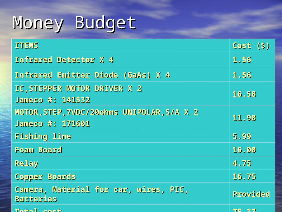
Money BudgetMoney BudgetITEMSITEMS Cost ($)Cost ($)
Infrared Detector X 4Infrared Detector X 4 1.561.56
Infrared Emitter Diode (GaAs) X 4Infrared Emitter Diode (GaAs) X 4 1.561.56
IC,STEPPER MOTOR DRIVER X 2IC,STEPPER MOTOR DRIVER X 2
Jameco #: 141532 Jameco #: 141532 16.5816.58
MOTOR,STEP,7VDC/20ohms UNIPOLAR,S/A X 2MOTOR,STEP,7VDC/20ohms UNIPOLAR,S/A X 2
Jameco #: 171601 Jameco #: 171601 11.9811.98
Fishing lineFishing line 5.995.99
Foam Board Foam Board 16.0016.00
RelayRelay 4.754.75
Copper BoardsCopper Boards 16.7516.75
Camera, Material for car, wires, PIC, Batteries Camera, Material for car, wires, PIC, Batteries ProvidedProvided
Total costTotal cost 75.1775.17

Project OrganizationProject Organization
David GoodingDavid Gooding Chief Electronics Chief Electronics EngineerEngineer
Erik Andersen Erik Andersen Mechanical Structure Mechanical Structure and Materials and Materials Engineer Engineer
Matt ElsnerMatt Elsner Assembly Code Assembly Code ProgrammerProgrammer
Anna VigilAnna Vigil Automated Box Automated Box Designer and TesterDesigner and Tester
Augustine TrujilloAugustine Trujillo Circuitry Designer Circuitry Designer and Tester and Tester

ScheduleScheduleDateDate TaskTask
April 17-25April 17-25 Box prototype and testingBox prototype and testing
May 6-8May 6-8 Rover and Circuit Board Parts orderingRover and Circuit Board Parts ordering
May 8-15May 8-15 Implementing Circuit Board DesignImplementing Circuit Board Design
May 15-22May 15-22 Testing and Programming PIC Testing and Programming PIC microcontroller with sensors microcontroller with sensors
May 25 to June 1May 25 to June 1 Testing motors with IC controllers via PIC Testing motors with IC controllers via PIC Assembly encoding Assembly encoding
June 1-10June 1-10 Construct Rover Construct Rover
June 10-15June 10-15 Implement circuit to RoverImplement circuit to Rover
June 15 to July 25June 15 to July 25 Addition changes and TestingAddition changes and Testing