Embed Size (px)
Citation preview
1
Critical Buckling Load Optimization of a Filament Wound Composite Cylindrical Underwater Structure
B.Acar, A.Yetgin, and E.Özaslan
Roketsan Missile Ind.
Abstract: Filament wound composite structures have high resistance to water corrosion which
makes them popular for military underwater applications besides their high strength to weight
ratio. The main loading condition for an underwater structure is hydrostatic external pressure
which generally causes structural instability or buckling rather than rupture of the structure. In
this study, a military underwater cylindrical Glass/Epoxy filament wound structure was analyzed
in terms of buckling. Abaqus/CAE and Isight tool with Response Surface Method were used.
Helical winding angle and thickness of helical and hoop layers with constant total thickness were
used as main variables to investigate the effects of them on the critical buckling pressure.
However, cylinder diameter, cylinder length, total thickness and material were kept constant as
design constraints. It is seen that the critical buckling pressure can be increased 5.5% by
changing the helical winding angle. Critical buckling pressure increases with increasing helical
winding angle from 30° to 58° and decreases with further increasing of helical winding angle
from 58° to 80°. Also, it is seen that the critical buckling pressure can be raised maximum 21% by
changing the thickness of helical layers with constant total thickness. Critical buckling pressure
increases with increasing of helical layer thickness from 2 mm to a certain value and falls after
that certain value up to 4 mm. In addition to individual effects, interaction effects of variables on
the critical buckling pressure were demonstrated. Also, optimum design point was determined,
and structural strength of optimized design was checked with Tsai-Wu failure criteria.
Keywords: Buckling, Composites, Design Optimization, Optimization
1. Introduction
Filament wound composite materials have been used in both civil and military underwater
structures due to their high strength to weight ratio and high resistance to salt water corrosion over
the past few years. The main loading condition of an underwater structure is hydrostatic pressure.
This type of loading generally causes structural instability or buckling rather than crushing of
structure [1]. When the cylindrical composite structure exposed to hydrostatic pressure load, the
buckling may be seen at a stress which is far lower than material strength. Because of this fact, the
designers should consider the buckling failure as well as crushing of structure. Dey A. et al. [2],
investigated the buckling behavior of carbon/epoxy filament wound stiffened thick walled
composite pressure vessel subjected to hydrostatic pressure. They concluded that stiffened
filament wound composite pressure vessel has higher critic buckling pressure than unstiffened
pressure vessel. Kim H.M. et al. [3], studied the finite element analysis of thick walled composite
2
pressure vessel under hydrostatic pressure load. They showed that solid and shell modeling of this
type structure gives comparable results in terms of critic buckling load. Also, they concluded that
finite element model with effective properties of laminate rather than separate modeling of hoop
and helical layers may give %40 errors from the actual hydrostatic experimental value. It is
showed by many investigators that the thin composite tubes subjected to internal pressure give
optimum strength values when they wound [±55]n angle [1,4-6]. The reason of this fact is that 55-
degree angle wound gives best response to loading ratio which is 2:1 circumferential and axial
components for internal pressure loading case. Messager T. et al. [7], performed an optimization
study to improve stability limit of a thin-walled laminated composite unstiffened vessel under
hydrostatic pressure loading. They showed that optimizing the stacking sequence may increase the
critic buckling load approximately %40.
In this study, a military underwater cylindrical filament wound composite structure which was
exposed to hydrostatic pressure was performed in terms of critical buckling load optimization.
Helical winding angle and thickness of helical/hoop layers with constant total thickness were used
as main variables to optimize the critical buckling pressure. However, cylinder diameter, cylinder
length, total thickness and material were kept constant as design constraints. Also, individual
effects and interaction effects of variable parameters on the critical buckling load were
demonstrated. Also, structural strength of optimized design was checked with using Tsai-Wu
failure criteria. Abaqus/CAE 2016 [8] and Isight [9] optimization tool were used for the study.
2. Problem Description and Finite Element Analysis
2.1 Problem description
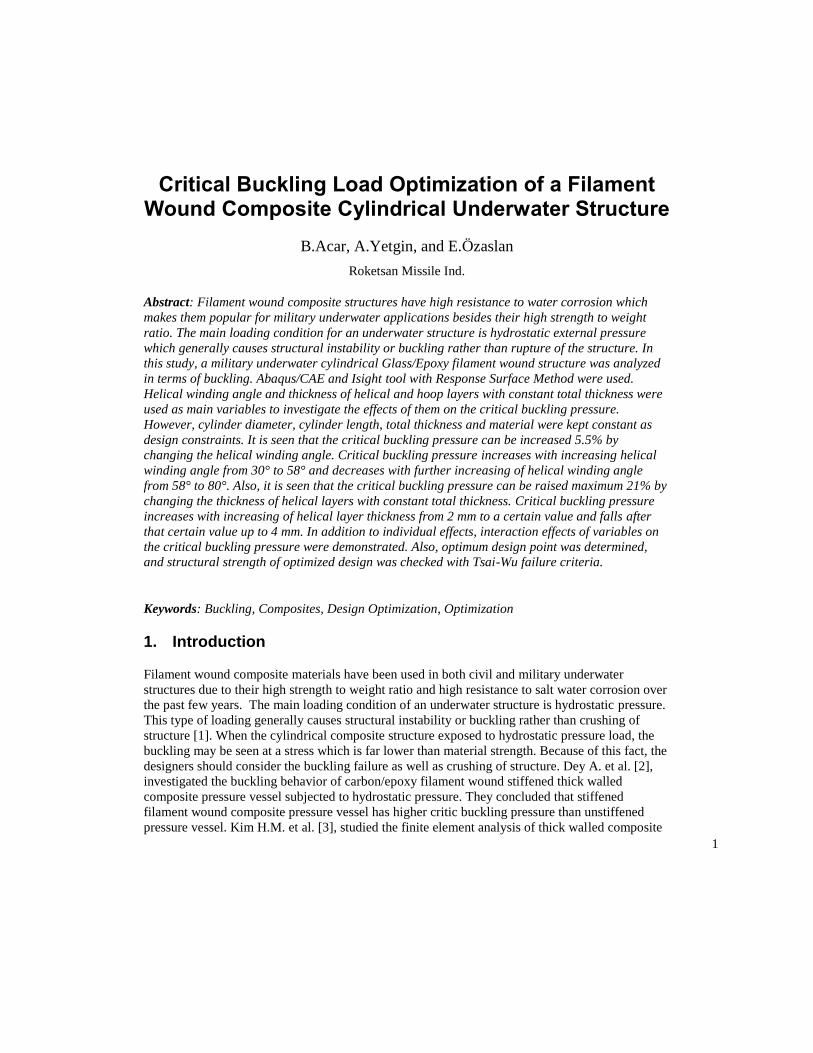
In this study, critical buckling load optimization of a deep sea cylindrical structure which exposed
to hydrostatic pressure load was performed. A schematic view of structure is shown in Figure1
where total composite section length L is 500 mm, inner diameter of composite part D is 288 mm
and total thickness of composite cylinder t is 6 mm. Both end closures are steel.
Figure 1. Schematic view of structure
Geometrical design constraints are total thickness t, cylinder length L and cylinder diameter D.
The effect of thickness ratio of helical/hoop layers (t_angle/t_hoop) with constant total thickness

3
(t) and winding angle of helical layers on the critical buckling load was investigated. Also,
winding angle and helical/hoop thickness optimization was performed in terms of critical buckling
load. Constrained and variable geometric parameters were shown in Figure 2.
Figure 2. Constrained and variable geometric parameters
The winding angle pattern was chosen as [(90)a / (θ)b / (90)a ] which is a typical characteristic
pattern to provide high critical buckling load and high structural strength [7]. Helical winding
angle range was given as; θ ϵ [30°……80°]. The thickness range of helical layers was given as;
t_angle ϵ [2…...4] mm.
The composite material is glass/epoxy which is used for underwater structures thanks to its high
resistance to salt water corrosion. The material properties of glass/epoxy are given in Table 1 and
Table 2.
Table 1. Material properties of Glass/Epoxy
E1 [GPa] 45.6
E2 [GPa] 16
E3 [GPa] 16
G12 [GPa] 5.88
G13 [GPa] 5.88
G23 [GPa] 5.9
v12 0.264
v13 0.264
v23 0.437

4
Table 2. Strength values of Glass/Epoxy
Xt [MPa] 1264
Xc [MPa] -812
Yt [MPa] 41.6
Yc [MPa] 146.4
S [MPa] 50
2.2 Finite element analysis
Buckling analysis was performed with Abaqus/CAE 2016 [8]. Composite cylindrical structure was
modelled with Abaqus Composite Layup Manager. Helical layers were modelled as +θ/-θ to
represent filament winding nature. Boundary conditions and loading for buckling analysis are
given in Figure 3 and Figure 4.
Figure 3. Boundary conditions

5
Figure 4. Loading for buckling analysis
3. DOE Procedure
In the DOE procedure, thickness of the helical layers is changed while keeping total thickness the
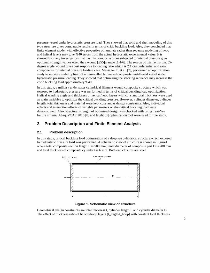
same. Another parameter is winding angle of helical layers. First step of the DOE process begins
with generating new input parameter as shown in Figure 5. In this study, design matrix is
generated using Latin Hypercube method. Design space is evenly divided into levels for each
parameter and design points are generated by randomly combining these levels.[9] Figure 6
illustrates, five design points that are selected from uniformly divided levels of parameters X1 and
X2. This method allows designer to select any number of design points which is greater than
parameters and more combinations can be investigated. [9]
6
Figure 5. Work flow
Figure 6. Latin Hypercube
Isight provides an easy to use environment to set up DOE process and post process the results.
Another advantage is seamless utilization of simulation products such as Abaqus. Isight sim-flow
used in this work is shown in Figure 7. In the component in the flow is a simcode which combines
an input text editor, command prompter and output text parser. In this component, design
parameters are written into buckling input file, solved and critical buckling factor is extracted from
dat file. Next component calculates pressure and edge loading corresponding buckling load and
stress analysis is solved afterwards. In the final component, failure index is calculated using stress
results.

7
Figure 7. Isight Sim-Flow view
4. Results
The first buckling eigenvalue of buckling analysis was accepted as critical buckling load. The
shapes of first buckling modes were shown in Figure 8. Characteristic buckling shapes for
laminated cylinders were obtained as expected.
Figure 8. First buckling shapes for analysis
Firstly, the effects of the geometric variables (helical winding angle and thickness of helical layer
with constant total thickness) on the critical buckling load were investigated with using Response
Surface Method (RSM).

8
From the helical winding angle main effect plot (Figure 9), it is seen that the helical angle variance
changes the critical buckling load maximum %5.5 for the winding angle range of 30° to 80°. The
critical buckling load increases with increasing of helical winding angle from 30° to a certain
value. From this certain winding angle, the critical buckling load decreases with increasing the
helical winding angle until 80°. This fact can be expressed as the stiffness contribution of helical
layers to axial and hoop directions is optimum at a certain winding angle. When the helical
winding angle is less than optimum value, the helical layers give less stiffness contribution to
hoop direction than optimum winding angle. Similarly, when the helical winding angle is more
than optimum value, the helical layers give less stiffness contribution to axial direction than
optimum winding angle.
Figure 9. Main effect plot of helical winding angle
From the helical layer thickness main effect plot (Figure 10), it is seen that the thickness of helical
layers with constant total thickness changes the critical buckling load maximum %21 for the
helical thickness range of 2 mm to 4 mm. The critical buckling load increases with increasing of
helical layer thickness from minimum value to a certain value. The critical buckling load decrease
from this certain value to maximum thickness value. This behavior is similar to helical winding
angle behavior. When the helical layer thickness is less than the optimum value, the helical layers
give less stiffness contribution to axial direction than optimum thickness value. Similarly, when
the helical winding angle is more than optimum value, the total hoop direction stiffness is less than
optimum thickness value.

9
Figure 10. Main effect plot of helical layer thickness
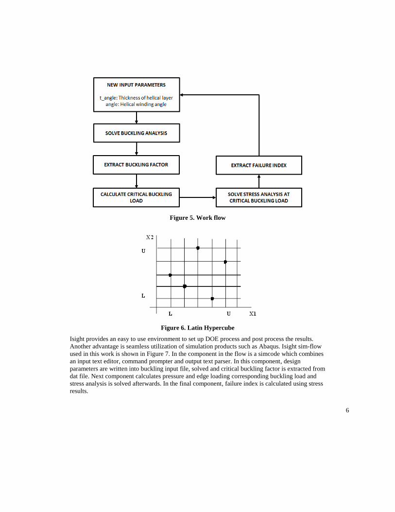
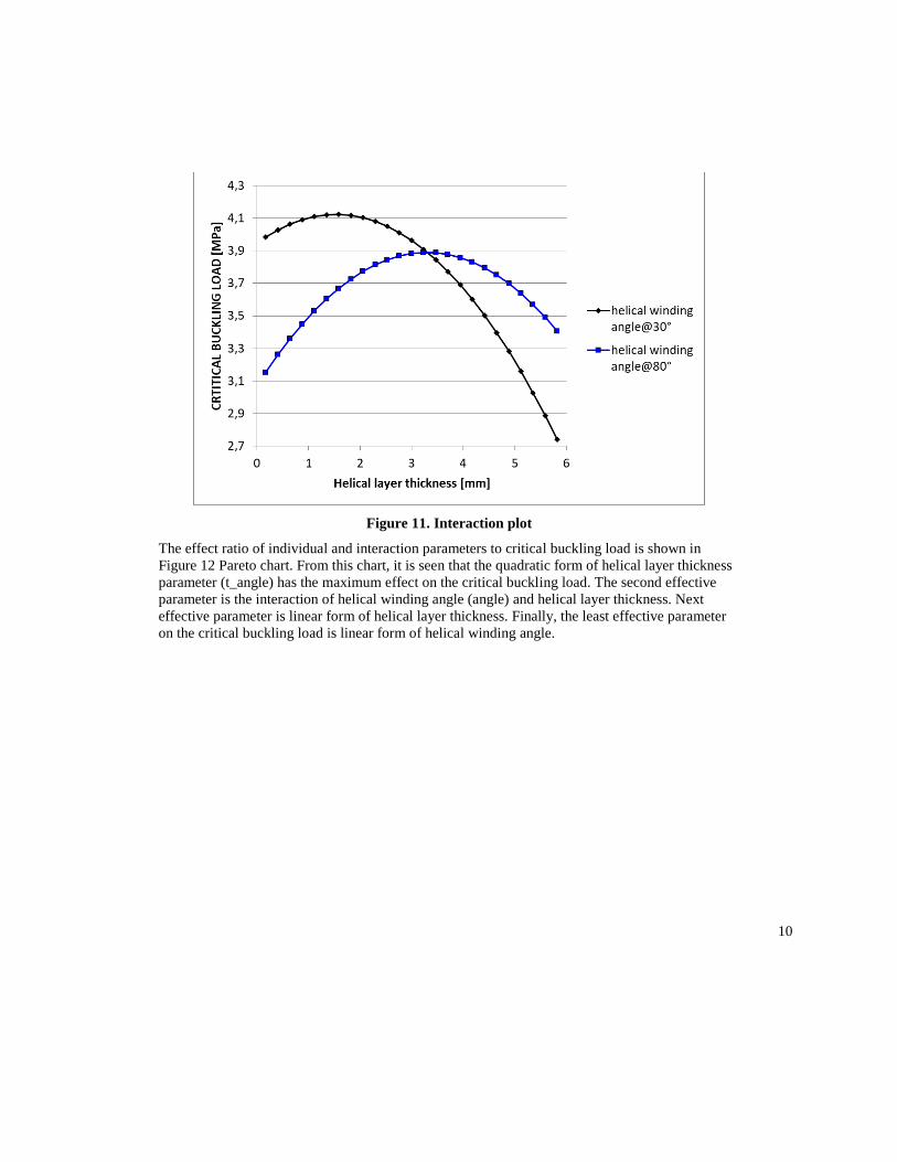
From the interaction plot (Figure 11), the effect of both parameters on the critical buckling load
can be seen instead of individual effects of parameters. It is obviously seen that 30° helical
winding angle gives higher critical buckling load than 80° for minimum helical layer thickness.
The reason of this fact is the high axial stiffness contribution of 30° helical winding angle to axial
direction. Oppositely, 80° helical winding angle gives higher critical buckling load than 30° for
maximum helical layer thickness. The reason of this fact is the high hoop stiffness contribution of
80° helical winding angle to hoop direction. Also, 30° and 80° helical winding angles give same
critical buckling load at a certain helical layer thickness value.
10
Figure 11. Interaction plot
The effect ratio of individual and interaction parameters to critical buckling load is shown in
Figure 12 Pareto chart. From this chart, it is seen that the quadratic form of helical layer thickness
parameter (t_angle) has the maximum effect on the critical buckling load. The second effective
parameter is the interaction of helical winding angle (angle) and helical layer thickness. Next
effective parameter is linear form of helical layer thickness. Finally, the least effective parameter
on the critical buckling load is linear form of helical winding angle.

11
Figure 12. Pareto chart
All these effects also can be seen in surface plot (Figure 13) in 3D space.
Figure 13. Surface plot
12
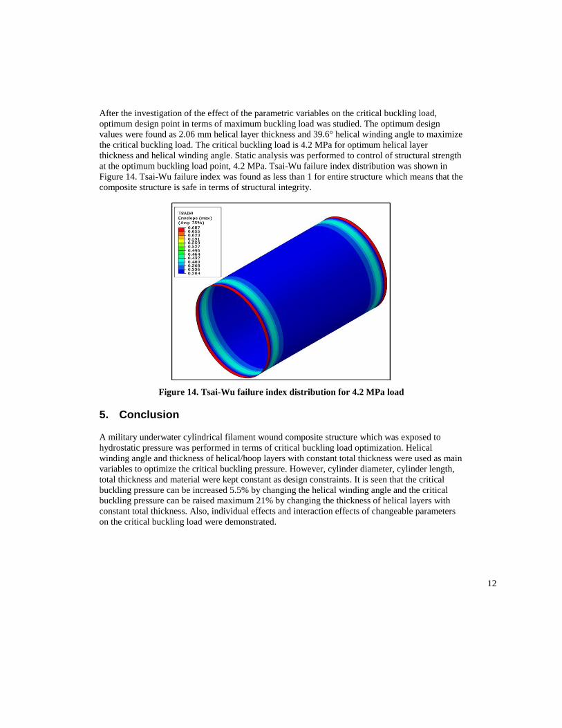
After the investigation of the effect of the parametric variables on the critical buckling load,
optimum design point in terms of maximum buckling load was studied. The optimum design
values were found as 2.06 mm helical layer thickness and 39.6° helical winding angle to maximize
the critical buckling load. The critical buckling load is 4.2 MPa for optimum helical layer
thickness and helical winding angle. Static analysis was performed to control of structural strength
at the optimum buckling load point, 4.2 MPa. Tsai-Wu failure index distribution was shown in
Figure 14. Tsai-Wu failure index was found as less than 1 for entire structure which means that the
composite structure is safe in terms of structural integrity.
Figure 14. Tsai-Wu failure index distribution for 4.2 MPa load
5. Conclusion
A military underwater cylindrical filament wound composite structure which was exposed to
hydrostatic pressure was performed in terms of critical buckling load optimization. Helical
winding angle and thickness of helical/hoop layers with constant total thickness were used as main
variables to optimize the critical buckling pressure. However, cylinder diameter, cylinder length,
total thickness and material were kept constant as design constraints. It is seen that the critical
buckling pressure can be increased 5.5% by changing the helical winding angle and the critical
buckling pressure can be raised maximum 21% by changing the thickness of helical layers with
constant total thickness. Also, individual effects and interaction effects of changeable parameters
on the critical buckling load were demonstrated.
13
6. References
[1] Kaddour, A.S, and Soden, P.D., “Failure of 55 Degree Filament Wound Glass/Epoxy
Composite Tubes Under Biaxial Compression,” Journal of Composite Materials, Vol. 32, No.
18/1998.
[2] Dey, A, Pandey, K.M, and Choudhury, P.L., “A Comparison Study of Filament Wound
Composite Cylindrical Shell Used in Under Water Vehicle Application by Finite Element
Method,” 5th International & 26th All India Manufacturing Technology, Design and Research
Conference (AIMTDR 2014) December 12th–14th, 2014, IIT Guwahati, Assam, India.
[3] Kim, H.M., Et al. “Buckling Analysis of Filament-Wound Thick Composite Cylinder Under
Hydrostatic Pressure,” International Journal of Precision Engineering and Manufacturing Vol. 11,
No. 6, Pp. 909-913, 2010.
[4] Davies, P, Chauchot P., “Composites for marine applications––part 2: underwater structures,”
In: Mechanics of composite materials and structures. Dordrecht: Kluwer Academic Publishers;
1999, p. 249–60.
[5] Soden, P.D., Kitching, R. and Tse, P.C., “Experimental Failure Stress [±55]° Filament Wound
Glass Fiber Reinforced Plastic Tubes Under Biaxial Loads,” Composites, 1989. Vol.20, p.125-
135.
[6] Soden, P.D., Et al. “The Strength of a Filament Wound Composite Under Biaxial Loading,”
Composites, 1978. Vol.9, p.247-250.
[7] Messager, T., Et al. “Optimal laminations of thin underwater composite cylindrical vessels,”
Composite Structures 58 (2002) 529–537.
[8] Abaqus Users Manual, Version 2016-1, Dassault Systémes Simulia Corp., Providence, RI.
[9] Isight Users Manual, Version 2017. Dassault Systémes Simulia Corp., Providence, RI.
7. Acknowledgment
This study is fully supported by Roketsan Missiles Ind. Inc., a major Turkish defense and
energetic systems manufacturer.