Embed Size (px)
Citation preview

ANSI/ANS-2.27-2008
criteria for investigations ofnuclear facility sites for
seismic hazard assessments
AN
SI/A
NS
-2.2
7-20
08
ANSI/ANS-2.27-2008
American National StandardCriteria for Investigations of
Nuclear Facility Sites forSeismic Hazard Assessments
SecretariatAmerican Nuclear Society
Prepared by theAmerican Nuclear SocietyStandards CommitteeWorking Group ANS-2.27
Published by theAmerican Nuclear Society555 North Kensington AvenueLa Grange Park, Illinois 60526 USA
Approved July 31, 2008by theAmerican National Standards Institute, Inc.

AmericanNationalStandard
Designation of this document as an American National Standard attests thatthe principles of openness and due process have been followed in the approvalprocedure and that a consensus of those directly and materially affected bythe standard has been achieved.
This standard was developed under procedures of the Standards Committee ofthe American Nuclear Society; these procedures are accredited by the Amer-ican National Standards Institute, Inc., as meeting the criteria for AmericanNational Standards. The consensus committee that approved the standardwas balanced to ensure that competent, concerned, and varied interests havehad an opportunity to participate.
An American National Standard is intended to aid industry, consumers, gov-ernmental agencies, and general interest groups. Its use is entirely voluntary.The existence of an American National Standard, in and of itself, does notpreclude anyone from manufacturing, marketing, purchasing, or using prod-ucts, processes, or procedures not conforming to the standard.
By publication of this standard, the American Nuclear Society does not insureanyone utilizing the standard against liability allegedly arising from or afterits use. The content of this standard ref lects acceptable practice at the time ofits approval and publication. Changes, if any, occurring through developmentsin the state of the art, may be considered at the time that the standard issubjected to periodic review. It may be reaffirmed, revised, or withdrawn atany time in accordance with established procedures. Users of this standardare cautioned to determine the validity of copies in their possession and toestablish that they are of the latest issue.
The American Nuclear Society accepts no responsibility for interpretations ofthis standard made by any individual or by any ad hoc group of individuals.Requests for interpretation should be sent to the Standards Department atSociety Headquarters. Action will be taken to provide appropriate response inaccordance with established procedures that ensure consensus on theinterpretation.
Comments on this standard are encouraged and should be sent to SocietyHeadquarters.
Published by
American Nuclear Society555 North Kensington AvenueLa Grange Park, Illinois 60526 USA
Copyright © 2008 by American Nuclear Society. All rights reserved.
Any part of this standard may be quoted. Credit lines should read “Extracted fromAmerican National Standard ANSI0ANS-2.27-2008 with permission of the publisher,the American Nuclear Society.” Reproduction prohibited under copyright conventionunless written permission is granted by the American Nuclear Society.
Printed in the United States of America

Foreword ~This Foreword is not part of American National Standard “Criteria for Investigations ofNuclear Facility Sites for Seismic Hazard Assessments,” ANSI0ANS-2.27-2008.!
This standard provides requirements and recommended practices for conductinginvestigations and acquiring data sets needed to characterize seismic sources forprobabilistic seismic hazard analysis ~PSHA!. The data sets provide informationfor site response and soil-structure interaction analyses needed for design ofthose facilities. They also are used to evaluate fault rupture and associatedsecondary deformation and other seismically induced ground failure hazards~e.g., liquefaction, ground settlement, slope failure!.
This standard is one of a group of four standards that establish requirements forthe seismic design of nuclear facilities. The overall objective of these standards isto achieve a risk-informed design that protects the public, the environment, andworkers from potential consequences of earthquakes. The other three standardsare American National Standards Institute0American Nuclear Society ANSI0ANS-2.26-2004, “Categorization of Nuclear Facility Structures, Systems, andComponents for Seismic Design”; ANSI0ANS-2.29-2008, “Probabilistic SeismicHazards Analysis”; and American Society of Civil Engineers0Structural Engi-neering Institute ASCE0SEI 43-05, “Seismic Design Criteria for Structures, Sys-tems, and Components in Nuclear Facilities.” The procedural relationship amongthese four standards is shown in Fig. A.
The seismic design process for nuclear facilities is based on the consequences ofseismic-initiated failure of structures, systems, and components ~SSCs!. The
Figure A – Schematic showing the relationships of the seismic standards
– i –

seismic design categories identified in ANSI0ANS-2.26-2004 and the design re-quirements specified in ASCE0SEI 43-05 satisfy target performance goals de-fined in terms of the annual probability of exceeding specified SSC performancelimits. Achieving a target performance goal is directly related to the probabilityof occurrence of a seismic load that is beyond design specifications. ANSI0ANS-2.29-2008 establishes procedures for performing a PSHA needed to supportselection of the seismic loads used in ASCE0SEI 43-05. This standard providesguidance for the geological and geotechnical investigations needed to provideinformation to support ~a! seismic source characterization input to the PSHA,~b! evaluation of surface fault rupture hazards, ~c! site response analyses, and~d! seismic-induced ground failure hazards.
This standard might reference documents and other standards that have beensuperseded or withdrawn at the time the standard is applied. A statement hasbeen included in the reference section that provides guidance on the use ofreferences.
Working Group ANS-2.27 of the ANS-25 Subcommittee to the Nuclear FacilitiesStandards Committee ~NFSC! of the American Nuclear Society ~ANS! had thefollowing membership at the time of approval of this standard:
K. L. Hanson ~Chair!, Geomatrix Consultants, Inc.W. R. Lettis ~Vice Chair!, William Lettis & Associates, Inc.
J. Ake, U.S. Nuclear Regulatory CommissionJ-C. Chen, Lawrence Livermore National LaboratoryC. J. Costantino, City University of New York, Civil Engineering DepartmentC. B. Crouse, URS Corporation, Inc.J. A. Egan, Geomatrix Consultants, Inc.J. K. Kimball, Defense Nuclear Facilities Safety BoardJ. L. King, IndividualR. C. Lee, Los Alamos National LaboratoryY. Li, U.S. Nuclear Regulatory CommissionJ. J. Litehiser, Bechtel Corporation, Inc.W. U. Savage, U.S. Geological SurveyD. P. Schwartz, U.S. Geological SurveyM. J. Shah, U.S. Nuclear Regulatory CommissionP. C. Thenhaus, ABS Consulting, Inc.
This standard was prepared under the guidance of NFSC Subcommittee ANS-25~Siting! of the ANS. At the time of the ballot, Subcommittee ANS-25 was com-posed of the following members:
C. A. Mazzola ~Chair!, Shaw Environmental, Inc.
J. S. Bollinger, Savannah River National LaboratoryC. J. Costantino, City University of New York, Civil Engineering DepartmentP. D. Fledderman, Westinghouse Savannah River CompanyD. F. Hang, University of Illinois–UrbanaK. L. Hanson, Geomatrix Consultants, Inc.J. J. Litehiser, Bechtel Corporation, Inc.S. L. Marsh, Southern California Edison CompanyB. A. Mohrman, Environmental Resources ManagementD. K. Ostrom, IndividualD. E. Pittman, Tennessee Valley AuthorityJ. B. Savy, Lawrence Livermore National LaboratoryR. D. Spence, UT-Battelle, LLCJ. D. Stevenson, J.D. Stevenson & Associates
The standard was processed and approved for submittal to the American NuclearStandards Institute for acceptance as an American National Standard. At thetime of approval of this standard, the NFSC had the following membership:
C. A. Mazzola ~Chair!, Shaw Environmental, Inc.R. M. Ruby ~Vice Chair!, Constellation Energy
– ii –

J. K. August, CORE, Inc.W. H. Bell, South Carolina Electric & Gas CompanyJ. R. Brault, Shaw MOX ProjectC. K. Brown, Southern Nuclear Operating CompanyR. H. Bryan, Tennessee Valley AuthorityK. R. Bryson, Shaw Environmental, Inc.T. Dennis, IndividualD. R. Eggett, AES EngineeringR. W. Englehart, U.S. Department of EnergyR. A. Hall, Exelon NuclearP. S. Hastings, Duke Energy (NuStart Liaison)R. A. Hill, ERIN Engineering & Research, Inc.N. P. Kadambi, U.S. Nuclear Regulatory CommissionM. P. LaBar, General AtomicsE. M. Lloyd, ExitechE. P. Loewen, General ElectricS. A. Lott, Los Alamos National LaboratoryJ. E. Love, Bechtel Power CorporationR. H. McFetridge, Westinghouse Electric CorporationC. H. Moseley, ASME/NQA Liaison (BWXT Y-12)D. G. Newton, AREVA NPW. N. Prillaman AREVA NPW. B. Reuland, IndividualD. M. Reynerson, Phoenix IndexR. E. Scott, IndividualD. J. Spellman, Oak Ridge National LaboratoryS. L. Stamm, Shaw, Stone & WebsterJ. D. Stevenson, IndividualC. D. Thomas, Jr., IndividualJ. A. Wehrenberg, Southern Nuclear Operating CompanyM. J. Wright, Entergy Operations
– iii –

– iv –
Contents Section Page
1 Scope . . . . . . . . . . . . . . . . . . . . . . . . . . . . . . . . . . . . . . . . . . . . . . . . . . . . . . . . . . . . . . . 1
2 Acronyms and definitions . . . . . . . . . . . . . . . . . . . . . . . . . . . . . . . . . . . . . . . . . . . . 12.1 List of acronyms . . . . . . . . . . . . . . . . . . . . . . . . . . . . . . . . . . . . . . . . . . . . . . . . 12.2 Definitions . . . . . . . . . . . . . . . . . . . . . . . . . . . . . . . . . . . . . . . . . . . . . . . . . . . . . 2
3 General requirements . . . . . . . . . . . . . . . . . . . . . . . . . . . . . . . . . . . . . . . . . . . . . . . . 5
4 Site-specific characterization criteria . . . . . . . . . . . . . . . . . . . . . . . . . . . . . . . . . 64.1 Investigations to support seismic source characterization for PSHA . . 7
4.1.1 Seismic source location and geometry . . . . . . . . . . . . . . . . . . . . . . 84.1.1.1 Fault . . . . . . . . . . . . . . . . . . . . . . . . . . . . . . . . . . . . . . . . . . . . 84.1.1.2 Volumetric source zones . . . . . . . . . . . . . . . . . . . . . . . . . . 12
4.1.2 Maximum earthquake magnitude . . . . . . . . . . . . . . . . . . . . . . . . . . 134.1.2.1 Maximum earthquake magnitude: Faults . . . . . . . . . . 134.1.2.2 Maximum earthquake magnitude: Volumetric source
zones . . . . . . . . . . . . . . . . . . . . . . . . . . . . . . . . . . . . . . . . . . 134.1.3 Earthquake recurrence . . . . . . . . . . . . . . . . . . . . . . . . . . . . . . . . . . . 14
4.1.3.1 Earthquake recurrence: Faults . . . . . . . . . . . . . . . . . . . . 144.1.3.2 Earthquake recurrence: Volumetric source zones . . . . 14
4.2 Fault rupture hazard characterization . . . . . . . . . . . . . . . . . . . . . . . . . . . . 154.3 Geotechnical investigations . . . . . . . . . . . . . . . . . . . . . . . . . . . . . . . . . . . . . . 16
4.3.1 Information review and site reconnaissance . . . . . . . . . . . . . . . . 164.3.2 Site investigations . . . . . . . . . . . . . . . . . . . . . . . . . . . . . . . . . . . . . . . . 16
4.3.2.1 Subsurface exploration . . . . . . . . . . . . . . . . . . . . . . . . . . . . 174.3.2.2 Laboratory testing . . . . . . . . . . . . . . . . . . . . . . . . . . . . . . . . 18
4.4 Characterization for site response analysis . . . . . . . . . . . . . . . . . . . . . . . 194.5 Site characterization for ground failure hazard . . . . . . . . . . . . . . . . . . . 20
4.5.1 Liquefaction of soils . . . . . . . . . . . . . . . . . . . . . . . . . . . . . . . . . . . . . . 204.5.2 Ground settlement . . . . . . . . . . . . . . . . . . . . . . . . . . . . . . . . . . . . . . . 214.5.3 Slope failure . . . . . . . . . . . . . . . . . . . . . . . . . . . . . . . . . . . . . . . . . . . . . 21
5 References . . . . . . . . . . . . . . . . . . . . . . . . . . . . . . . . . . . . . . . . . . . . . . . . . . . . . . . . . . 22
TablesTable 1 Guidance for levels of investigation to identify seismic sources
in different seismic environments for seismic design category~SDC-1 through SDC-5! sites . . . . . . . . . . . . . . . . . . . . . . . . . . . . . . 7
Table 2 General data types and their primary applications inidentifying and characterizing seismic sources . . . . . . . . . . . . . . 9
– v –


Criteria for Investigations ofNuclear Facility Sites for SeismicHazard Assessments1 Scope
This standard provides criteria and guidelinesfor conducting geological, seismological, and geo-technical investigations needed to provide in-formation to support the following:
~1! seismic source characterization input to aprobabilistic seismic hazard analysis ~PSHA!;
~2! evaluation of surface fault rupture hazard;
~3! site response analysis;
~4! seismic-induced ground failure hazard.
These criteria are applicable for Seismic De-sign Category ~SDC!-3, SDC-4, and SDC-5 struc-tures, systems, or components ~SSCs!.
This standard does not address the use ofPSHA results or the selection of design-basisevents for nuclear facilities. These topics arecovered in American National StandardsInstitute0American Nuclear Society ANSI0ANS-2.26-2004, “Categorization of Nuclear FacilityStructures, Systems, and Components for Seis-mic Design” @1#1! and American Society of CivilEngineers0Structural Engineering InstituteASCE0SEI 43-05, “Seismic Design Criteria forStructures, Systems, and Components in Nu-clear Facilities” @2# .
This standard is one of a series of nationalstandards designed to provide criteria andguidelines to promote uniform and effectiveassessment of seismic hazards at nuclear fa-cilities. These hazards must be properly iden-tified and characterized commensurate withthe level of risk and design requirements as-sociated with each nuclear facility as speci-fied in ANSI0ANS-2.26-2004 @1# and ASCE0SEI 43-05 @2# . As defined in ANSI0ANS-2.26-2004 @1# , a nuclear facility is a facility that
stores, processes, tests, or fabricates radio-active materials in such form and quantitythat a nuclear risk to the workers, to theoff-site public, or to the environment may ex-ist. These include, but are not limited to, nu-clear fuel manufacturing facilities; nuclearmaterial waste processing, storage, fabrica-tion, and reprocessing facilities; uranium en-richment facilities; tritium production andhandling facilities; and radioactive materialslaboratories. Additional criteria may be spec-ified by the applicable regulatory authority.
This standard outlines standard criteria andprocedures to collect data needed as input toprobabilistic analysis of seismic hazards atnuclear facilities as specified in ANSI0ANS-2.29-2008, “Probabilistic Seismic HazardsAnalysis” @3#. Appropriate approaches are out-lined to ensure that the current state-of-the-art methodology is being used in the sitecharacterization. The selection of specific tech-niques and level of detail required to assessseismic and seismic-induced hazards is de-pendent on both the nature of the nuclearfacility ~i.e., SDC2! as defined by ANSI0ANS-2.26-2004 @1# ! and site-specific conditions.3!
2 Acronyms and definitions
2.1 List of acronyms
ANS: American Nuclear Society
ANSI: American National Standards Institute
ASCE/SEI: American Society of Civil Engineers0Structural Engineering Institute
ASTM: American Society for Testing andMaterials
BPT: Becker penetration test
1! Numbers in brackets refer to corresponding numbers in Sec. 5, “References.”2! The SDCs used in this standard are not the same as the SDCs referred to in the International Building Code~IBC!.3! In this standard, material that is double-indented indicates a commentary.
1

CEUS: Central and Eastern United States
CPT: cone penetration test
EPRI: Electric Power Research Institute
GPS: global positioning system
IBC: International Building Code
LiDAR: light detection and radar
MCE: maximum considered earthquake
NEHRP: National Earthquake Hazards Reduc-tion Program
NRC: U.S. Nuclear Regulatory Commission
PGA: peak ground acceleration
PGV: peak ground velocity
PSHA: probabilistic seismic hazard analysis
QA: quality assurance
RQD: rock quality designation
SASW: spectral analysis of surface waves
SDC: seismic design category
SPT: standard penetration test
SSC: structure, system, or component
SSHAC: Senior Seismic Hazard AnalysisCommittee
SSI: soil-structure interaction
UHRS: uniform hazard response spectra
2.2 Definitions
accelerogram: A representation ~either re-corded, modified recorded, or synthetic! of theacceleration of the ground during an earth-quake. The accelerogram contains acceleration-time-data pairs.
aleatory variability: The variability inher-ent in a nondeterministic ~i.e., stochastic, ran-dom! phenomenon ~see “variability”!. Aleatoryvariability is accounted for by modeling thephenomenon in terms of a probability model.In principle, aleatory uncertainty cannot bereduced by the accumulation of more data oradditional information, but the detailed char-acteristics of the probability model can be im-proved. Sometimes aleatory variability is called“randomness.”
area source: An area of the earth’s crust thatis assumed to have relatively uniform earth-
quake source characteristics for use in thePSHA. ~See also “volumetric source zone.”!
background source zone: A part of the earth’scrust, usually of large areal dimension, withinwhich potentially damaging earthquakes couldoccur that are not associated either with knownfault sources or even with the uniform pattern,rate, or style of deformation or seismicity com-monly identified with volumetric seismic sourcezones. In PSHA calculations, earthquakes thatcannot be associated with other sources defaultto a background source zone.
blind fault: A blind fault is a fault that doesnot rupture all the way up to the surface andconsequently does not have a surface trace.These features are usually associated withthrust faults, which are formed by compressivestresses. Blind thrust faults do not penetratethe uppermost layers of crust, but they causethe surface layers to fold over them as theydeform, forming a telltale hill at the surfacethat reveals their presence to observers.
Central and Eastern United States (CEUS):That portion of the United States east of theRocky Mountains ~approximately the 104th
parallel!.
concealed fault: A fault that once ruptured tothe earth’s surface but that has subsequentlybeen buried by deposition of material atop thesurface trace during the period between sur-face ruptures.
coseismic: A term that relates an area or oc-currence of a phenomenon to the simultaneousarrival of earthquake waves.
epistemic uncertainty: Uncertainty attrib-utable to incomplete knowledge about a phe-nomenon that affects the ability to model it.Epistemic uncertainty is captured by consider-ing a range of model parameters within a givenexpert interpretation or multiple expert inter-pretations each of which is assigned an asso-ciated weight representing statistical confidencein the alternatives. In principle, epistemic un-certainty can be reduced by the accumulationof additional information associated with thephenomenon. The uncertainty in the param-eters of the probability distribution of a ran-dom phenomenon is epistemic.
American National Standard ANSI0ANS-2.27-2008
2
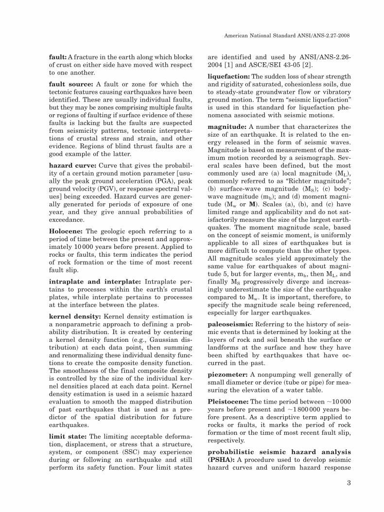
fault: A fracture in the earth along which blocksof crust on either side have moved with respectto one another.
fault source: A fault or zone for which thetectonic features causing earthquakes have beenidentified. These are usually individual faults,but they may be zones comprising multiple faultsor regions of faulting if surface evidence of thesefaults is lacking but the faults are suspectedfrom seismicity patterns, tectonic interpreta-tions of crustal stress and strain, and otherevidence. Regions of blind thrust faults are agood example of the latter.
hazard curve: Curve that gives the probabil-ity of a certain ground motion parameter @usu-ally the peak ground acceleration ~PGA!, peakground velocity ~PGV!, or response spectral val-ues# being exceeded. Hazard curves are gener-ally generated for periods of exposure of oneyear, and they give annual probabilities ofexceedance.
Holocene: The geologic epoch referring to aperiod of time between the present and approx-imately 10 000 years before present. Applied torocks or faults, this term indicates the periodof rock formation or the time of most recentfault slip.
intraplate and interplate: Intraplate per-tains to processes within the earth’s crustalplates, while interplate pertains to processesat the interface between the plates.
kernel density: Kernel density estimation isa nonparametric approach to defining a prob-ability distribution. It is created by centeringa kernel density function ~e.g., Gaussian dis-tribution! at each data point, then summingand renormalizing these individual density func-tions to create the composite density function.The smoothness of the final composite densityis controlled by the size of the individual ker-nel densities placed at each data point. Kerneldensity estimation is used in a seismic hazardevaluation to smooth the mapped distributionof past earthquakes that is used as a pre-dictor of the spatial distribution for futureearthquakes.
limit state: The limiting acceptable deforma-tion, displacement, or stress that a structure,system, or component ~SSC! may experienceduring or following an earthquake and stillperform its safety function. Four limit states
are identified and used by ANSI0ANS-2.26-2004 @1# and ASCE0SEI 43-05 @2# .
liquefaction: The sudden loss of shear strengthand rigidity of saturated, cohesionless soils, dueto steady-state groundwater f low or vibratoryground motion. The term “seismic liquefaction”is used in this standard for liquefaction phe-nomena associated with seismic motions.
magnitude: A number that characterizes thesize of an earthquake. It is related to the en-ergy released in the form of seismic waves.Magnitude is based on measurement of the max-imum motion recorded by a seismograph. Sev-eral scales have been defined, but the mostcommonly used are ~a! local magnitude ~ML!,commonly referred to as “Richter magnitude”;~b! surface-wave magnitude ~MS!; ~c! body-wave magnitude ~mb!; and ~d! moment magni-tude ~Mw or M!. Scales ~a!, ~b!, and ~c! havelimited range and applicability and do not sat-isfactorily measure the size of the largest earth-quakes. The moment magnitude scale, basedon the concept of seismic moment, is uniformlyapplicable to all sizes of earthquakes but ismore difficult to compute than the other types.All magnitude scales yield approximately thesame value for earthquakes of about magni-tude 5, but for larger events, mb, then ML, andfinally MS progressively diverge and increas-ingly underestimate the size of the earthquakecompared to Mw. It is important, therefore, tospecify the magnitude scale being referenced,especially for larger earthquakes.
paleoseismic: Referring to the history of seis-mic events that is determined by looking at thelayers of rock and soil beneath the surface orlandforms at the surface and how they havebeen shifted by earthquakes that have oc-curred in the past.
piezometer: A nonpumping well generally ofsmall diameter or device ~tube or pipe! for mea-suring the elevation of a water table.
Pleistocene: The time period between ;10 000years before present and ;1 800 000 years be-fore present. As a descriptive term applied torocks or faults, it marks the period of rockformation or the time of most recent fault slip,respectively.
probabilistic seismic hazard analysis(PSHA): A procedure used to develop seismichazard curves and uniform hazard response
American National Standard ANSI0ANS-2.27-2008
3
spectra for determining the ground motion at asite to be used for seismic design. Aleatory vari-ability and epistemic uncertainty are capturedin a PSHA. Criteria and guidance for conduct-ing a PSHA are provided in ANSI0ANS-2.29-2008 @3# .
Quaternary: The geologic period comprisingthe past ;1 800 000 years.
randomness: See “aleatory uncertainty.”
recurrence interval: The mean time periodbetween earthquakes of a given magnitude.
response spectrum: A curve calculated froman earthquake accelogram that gives the valueof peak response in terms of acceleration, ve-locity, or displacement of a damped linear os-cillator, with a given damping ratio, as a functionof its period, or frequency of vibration.
seismic design category (SDC): A categoryassigned to an SSC that is a function of theseverity of adverse radiological and toxicologi-cal effects of the hazards that may result fromthe seismic failure of the SSC on workers, thepublic, and the environment. SSCs may be as-signed to SDCs that range from 1 through 5.For example, a conventional building whose fail-ure may not result in any radiological or tox-icological consequences is assigned to SDC-1; asafety-related SSC in a nuclear material pro-cessing facility with a large inventory of radio-active material may be placed in SDC-5. Inthis standard, the term “SDC” has a differentmeaning than in the 2006 International Build-ing Code� ~2006 IBC! @4# . ANSI0ANS-2.26-2004 @1# provides guidance on the assignmentof SSCs to SDCs.
seismic source: Faults or volumes within theearth where future earthquakes are expectedto occur. In a PSHA, all seismic sources with apotential to contribute significantly to the haz-ard are considered.
seismic source characteristics: The param-eters that characterize a seismic source forPSHA, including source geometry, probabilityof activity, maximum magnitude, and earth-quake recurrence.
seismotectonic: Rock-deforming processes andresulting structures and seismicity that occurover large sections of the earth’s crust and up-per mantle.
seismogenic crust: The brittle portion of theearth’s crust capable of generating earthquakes.
shall, should, may: The word “shall” is usedto denote a requirement; the word “should” isused to designate a recommendation; and theword “may” is used to denote permission, nei-ther a requirement nor a recommendation.
site response (amplification): The amplifi-cation ~i.e., increase or decrease! of earthquakeground motion by rock and soil near the earth’ssurface in the vicinity of the site of interest.Topographic effects, the effect of the water table,and basin edge wave propagation effects aresometimes included under site response.
spectral analysis of surface waves (SASW):An in situ seismic method for determining shear-wave-velocity profiles. It uses the dispersivecharacteristics of surface waves to determinethe variation of the shear wave velocity ~i.e.,shear modulus! of layered systems at depth.
structure, system, or component (SSC): Astructure is an element, or a collection of ele-ments, to provide support or enclosure, such asa building, free-standing tanks, basins, dikes,or stacks. A system is a collection of compo-nents assembled to perform a function, such aspiping; cable trays; conduits; or heating, venti-lation, and air-conditioning. A component is anitem of mechanical or electrical equipment, suchas a pump, valve, or relay, or an element of alarger array, such as a length of pipe, elbow, orreducer.
target performance goal: Target mean an-nual frequency of an SSC exceeding its speci-fied limit state. Target performance goals of1 � 10�40year, 4 � 10�50year, and 1 � 10�50yearare used in ASCE0SEI 43-05 @2# for SSCs de-fined at SDC-3 or higher.
Tertiary: The geologic period from 1 800 000years before present to 63 000 000 years beforepresent.
uncertainty: See “epistemic uncertainty” and“aleatory variability.”
uniform hazard response spectra (UHRS):A response spectrum derived such that theannual probability of exceeding the spectralquantity ~i.e., spectra acceleration, spectral dis-placement, etc.! is the same for all oscillatorfrequencies. A UHRS is determined in accor-dance with ANSI0ANS-2.29-2008 @3# .
American National Standard ANSI0ANS-2.27-2008
4
variability: See “epistemic uncertainty” and“aleatory variability.”
volumetric source zone: A volume of theearth’s crust within which future seismicity isassumed to have distributions of source prop-erties and locations of energy release that donot vary in time and space.
3 General requirements
The geological, seismological, hydrological, andgeotechnical characteristics of a site and itsenvirons shall be investigated in sufficient scopeand detail necessary to support the evalua-tions required by ANSI0ANS-2.29-2008 @3# andASCE0SEI 43-05 @2# and to support the objec-tives of ANSI0ANS-2.26-2004 @1# .
The description of the site shall, at a mini-mum, include the following information:
~1! geographical coordinates of the site forwhich there shall be no ambiguity for esti-mating distances from the site to the sourcesof potential hazards;
~2! general location map to clearly define theboundary of the site and to show the distancefrom the site to natural and man-made fea-tures ~e.g., rivers, lakes, oceans, volcanoes,faults, dams, levees, steep slopes! and tosources of potential seismic or seismic-inducedhazards ~e.g., sources of earthquakes, land-slides, liquefaction-susceptible deposits!;
~3! detailed mapping of topographic, hydro-logic, and surface and subsurface geologicmaterials and features, as appropriate, forthe particular site conditions, with scalesand contours suitable for seismic hazardassessment.
Site characterization shall be carried out by areview of pertinent literature and field inves-tigations and shall follow the detailed require-ments given in Sec. 4. Subject matter expertswith knowledge and experience for fulfillingrequirements specif ied in ANSI0ANS-2.29-2008 @3# should define the program of investi-gations. Data and other information obtainedfrom prior investigations may be used, if sup-plemented by additional investigations at thespecific locations as necessary to meet the re-quirements elsewhere in this standard and in
ANSI0ANS-2.29-2008 @3# and ASCE0SEI 43-05@2# .
Site characterization activities shall be per-formed under an appropriate quality assur-ance ~QA! program. The QA program should beconducted within the framework of the risk-informed basis for seismic design categoriza-tion and associated target performance goalsas outlined in ANSI0ANS-2.26-2004 @1# andASCE0SEI 43-05 @2# , respectively, with an in-creasing level of rigor employed from SDC-3,SDC-4, and SDC-5. This program shall includetechnical peer review by independent qualifiedpersonnel with extensive knowledge and expe-rience in pertinent aspects of site characteriza-tion. The peer review should help establish thesite characterization program at the outset, helpresolve site-specific problems as they emerge,and provide guidance for compliance with ap-plicable state and federal regulatory criteria.
Site characterization studies shall be adequateto understand and quantify epistemic uncer-tainty in the assessment of parameters neededas input to PSHAs.
ANSI0ANS-2.26-2004 @1# identifies five seis-mic design categories, SDC-1 through SDC-5,and specifies the use of 2006 IBC/ASCE0SEI7-05, “Minimum Design Loads for Buildingsand Other Structures” @5# for design of SDC-1and SDC-2. Therefore, for sites containingfacilities with SSCs only in SDC-1 or SDC-2,a site-specific PSHA is not required. ANSI0ANS-2.26-2004 @1# specifies use of ASCE0SEI43-05 @2# design methods for SDC-3, SDC-4,and SDC-5, and ASCE0SEI 43-05 @2# requiresa PSHA prepared in accordance with ANSI0ANS-2.29-2008 @3# . For sites containing facil-ities with SSCs in SDC-3, SDC-4, or SDC-5,site-specific characterization criteria to sup-port a PSHA are provided in the followingsections of this standard.
Results of a PSHA are sensitive to aleatoryvariability and epistemic uncertainty in theparameters that describe seismic sources, re-currence relationships, and ground motion at-tenuation relationships. An explicit treatmentof this uncertainty is required for input intothe probabilistic analysis. As discussed in Bud-nitz et al. ~1997! @6# @also known as the Se-nior Seismic Hazard Analysis Committee~SSHAC! study#, PSHA incorporates both alea-tory variability and epistemic uncertainty.Aleatory variability refers to the natural ran-domness in a process. Randomness is a char-
American National Standard ANSI0ANS-2.27-2008
5
acteristic of the natural physical process, andincreasing the amount of data will not neces-sarily reduce the amount of variability butonly help in characterizing it more accu-rately. Classification of aleatory variabilityand epistemic uncertainty is model depen-dent and somewhat arbitrary. It is a matterof convention, modeling capabilities, and math-ematical assumptions and convenience. Ex-amples of elements that are modeled asaleatory variability are variation in the peakground motion of individual recordings abouta median ground motion relationship, andthe location and magnitude of the next earth-quake. Epistemic uncertainty is the scien-tific uncertainty in the process due to limiteddata and knowledge. It quantifies our confi-dence in the characterization of inherent vari-ability in nature. Examples of epistemicuncertainties are alternative admissible mod-els of ground motion attenuation and uncer-tainty in the long-term rate of slip on aparticular fault. This uncertainty is depen-dent on the knowledge of the physicalphenomena and could be due to different ad-missible physical interpretations, mathemat-ical formulations, and parameters for a givenphenomenon ~see ANSI0ANS-2.29-2008 @3# fora more complete discussion of uncertaintytreatment in PSHA!. With additional data itcould be possible to reduce epistemic uncer-tainty. For example, where boreholes are fewor nonexistent, one simple test may providesufficient evidence to eliminate possible al-ternative stratigraphic models.
4 Site-specific characterizationcriteria
The scope and degree of detail of investigationsto assess seismic and seismic-induced hazardsshall be based on
~1! the SDC of the SSCs making up thefacilities;
~2! the geological and seismotectonic envi-ronment of the site region;
~3! the extent of prior knowledge, investiga-tions, and data regarding the site and siteregion;
~4! the complexity of the surface and subsur-face conditions at the site as inferred fromprevious information and from preliminarysite investigations.
Although more detailed investigations gener-ally are appropriate for facilities havinghigher SDC levels, investigations of lesserscope and detail may be appropriate whenthe existing knowledge of the site and re-gion is extensive and up-to-date. Similarly,although less detailed investigations gener-ally are commensurate with lower SDC lev-els, more comprehensive investigations maybe needed if a site hazard exists or if in-vestigations to define the hazards have notpreviously been conducted. The detailed re-quirements in this section are applicable forobtaining the site information that is neededfor performing a PSHA in accordance withANSI0ANS-2.29-2008 @3# guidance. Generalguidance for characterizing seismic sourcesfor reactor facilities and storage facilitiesfor dry cask independent spent-fuel storageand monitored retrievable storage installa-tions is provided in U.S. Nuclear Regula-tory Commission ~NRC! Regulatory Guide1.165 @7# , NRC Regulatory Guide 3.73 @8# ,and NRC Regulatory Guide 1.208 @9# . Theseregulatory guides provide guidance for lev-els of investigation for the site region~i.e., 320-km radius!, site vicinity ~i.e., 40-kmradius!, site area ~i.e., 8-km radius!, andsite ~i.e., 1-km radius!. This standard usessimilar terminology to describe areas ofinvestigation.
All investigations to evaluate the geological,hydrogeological, seismological, geophysical,and geotechnical aspects of a site should be-gin with a review of available information forthe site region and a field reconnaissance ofthe site area. This review and field reconnais-sance provide an understanding of existingknowledge and site conditions so that an ef-ficient and cost-effective program of investi-gation can be designed to address issuesimportant to the assessment of geologic andseismic hazards at each site.
Current and historical information that shouldbe compiled and reviewed include
~1! earthquake catalogs, with seismicity in-formation and time histories;
~2! topographic, geological, geophysical, hy-drogeological, and soil maps;
~3! aerial photographs and other remote-sensing imagery;
~4! digital elevation model ~DEM! data @e.g.,light detection and radar ~LiDAR! data, ormultibeam bathymetric data#;
American National Standard ANSI0ANS-2.27-2008
6

~5! geological, seismological, geophysical,and geotechnical reports and other relatedliterature;
~6! well records and hydrological data;
~7! records of landslides, f loods, tsunamis,ground motions, and subsidence and of otherevents of geological, seismological, and geo-technical significance;
~8! records of past geotechnical performanceof other sites and structures in the sitevicinity.
Field reconnaissance evaluations of the site areashould include
~1! evaluation of geomorphic, hydrological,and surface geological features;
~2! evaluation of geology and soils, includingidentifying rock outcroppings, soil condi-tions, evidence of past landslides or soilliquefaction, faults, fracture traces, and geo-logical contacts.
Field reconnaissance of the site vicinity shouldbe conducted to evaluate Quaternary or possi-ble Quaternary faults for which adequate in-formation needed to assess the timing andsize of Quaternary fault displacement is notavailable.
4.1 Investigations to support seismicsource characterization for PSHA
Seismic sources define faults or volumes withinthe earth where future earthquakes are ex-pected to occur. All seismic sources with apotential to substantially affect the designor performance of nuclear facilities at a siteshall be identified and characterized as out-lined in ANSI0ANS-2.29-2008 @3#. Table 1 sum-marizes guidance for the level of investigationregarding seismic source characterization basedon the seismic environment and SDC of thefacility.
Seismic sources represent locations within theearth that can reasonably be assumed to haveuniform seismic characteristics, distinct from
Table 1 – Guidance for levels of investigation to identify seismic sources in differentseismic environments for seismic design category (SDC-1 through SDC-5) sites
Design response spectra3)
Strengthof seismic
environment1)
Maximum consideredearthquake (MCE)spectral response
acceleration2) SDC-1 and SDC-24) SDC-3 and SDC-44) SDC-54)
Low ,0.1 g Use 2006 IBC/ASCE0SEI7-05 @4,5#
Characterize back-ground earthquake andsources of earthquakesthat contribute �5% atthe site.
Identify and character-ize fault sources andvolumetric source zoneswithin 320 km and moredistant sources of earth-quakes that contribute�5% at the site.Moderate 0.1 to 0.3 g Use 2006 IBC/ASCE0SEI
7-05 @4,5#Same as above.
High .0.3 g Use 2006 IBC/ASCE0SEI7-05 @4,5#
Same as above; alsocharacterize in detail allQuaternary faults andvolumetric source zoneswithin 40 km.
Same as above; charac-terize in detail Quater-nary faults within 40km of the site.
1! Defined in ANSI0ANS-2.29-2008 @3# .
2! Based on the seismic maps provided in 2006 IBC @4# for the MCE ground motion spectral response accelerations ~for0.2- and 1.0-second periods, 5% of critical damping! and Site Class B as defined by the National Earthquake HazardsReduction Program ~NEHRP! ~2003! @12# . The larger of the two values is used to define the strength of seismicenvironment.
3! Following ASCE0SEI 43-05 @2# , ~1! use 2006 IBC/ASCE0SEI 7-05 @4,5# for SDC-1 and SDC-2 facility sites; ~2! useANSI0ANS-2.29-2008 @3# , and select UHRS at 4 � 10�40year ~mean! and 10�40year ~mean! for SDC-30SDC-4 and SDC-5facility sites, respectively.
4! Defined in ANSI0ANS-2.26-2004 @1# .
American National Standard ANSI0ANS-2.27-2008
7
those of neighboring sources. The types ofsources and the means of characterizing theirearthquake behavior vary with the seismo-tectonic environment. In much of the West-ern United States, individual faults can beidentified and treated as distinct seismicsources. Most large earthquakes have oc-curred on recognized or mappable faults or inassociation with Quaternary folds. In the Pa-cific Northwest and Alaska, subduction zonesources include interface and intraslab sources,in addition to crustal sources in the overrid-ing plate. In the Central and Eastern UnitedStates ~CEUS! ~i.e., east of the Rocky Moun-tains!, the causative link between the occur-rence of large earthquakes and mapped faultsis less clear than in the Western United States.Despite general agreement that large earth-quakes in the CEUS result from slippage alongfault surfaces, a clear association of even thelargest historical earthquakes ~e.g., the 1886Charleston, South Carolina, earthquake! withparticular faults has been difficult to deter-mine. Thus, in the CEUS, earthquake sourcesare generally defined as areas or volumetricsource zones. In some cases, where there issufficient information to suggest the localiza-tion of repeated large-magnitude events, faultsources are modeled to account for such re-peating large-magnitude earthquakes.
Appropriate earth sciences data to support theidentification and characterization of seismicsources shall be collected. Seismic source char-acterization parameters needed for input forPSHA include data for ~a! three-dimensionalseismic source location and geometry, ~b! max-imum earthquake magnitude, and ~c! earth-quake recurrence. The procedures and criteriafor developing the appropriate earth sciencesinput for these parameters are discussed be-low. The utilization of this information andmethods to quantify the uncertainty associatedwith the estimation of seismic source param-eters in the context of a PSHA are provided inANSI0ANS-2.29-2008 @3# .
Discussions of the methods and scientific basesfor characterizing seismic sources for PSHAare provided by Reiter ~1990! @10# , SSHAC~1997! @6#, and McGuire ~2004! @11#. The scopeof geological characterization studies neededto assess seismic source parameters variesdepending on ~a! the type of facility ~i.e., SDCof SSCs!, ~b! the quality of available data,and ~c! the sensitivity of the hazard results tothe uncertainty in one or more of theseparameters.
4.1.1 Seismic source location andgeometry
As specified in ANSI0ANS-2.29-2008 @3# , eachseismic source shall be defined by its locationand geometry so that the distance distributionto a site of interest can be calculated in thehazard analysis.
The area of investigation shall be defined bythe radial distance from the site that is re-quired to include all earthquake sources thatmight significantly contribute to earthquakeground motions within the frequency band ofinterest at the site ~Table 1!. For example, thesize of the area of investigation could be dif-ferent between locations in the CEUS and West-ern United States due to the very differentcrustal properties governing ground motion at-tenuation in each region. It will also dependon the response frequency of the SSC. A facil-ity that contains SSCs sensitive to low-frequency excitation would require the carefulconsideration of distant moderate to large earth-quakes that are capable of propagating signif-icant low-frequency energy to considerabledistances. The choice of an investigation areaand justification of that choice shall be theresponsibility of the investigator. The resultsof a preliminary PSHA or sensitivity analysismay be utilized to aid in determining the areaof investigation.
Approaches for assessing the location and ge-ometry of fault sources and source zones arepresented below. Data commonly used to iden-tify and characterize seismic sources are sum-marized in Table 2.
4.1.1.1 Fault
Any fault that, if active, would pose a hazardfrom either surface deformation ~i.e., folding orfaulting! or vibratory ground motion shall beevaluated. Faults that have slipped and geo-logic structures that have deformed during theQuaternary period should be considered poten-tially active and evaluated to assess timing ofmost recent movement and rate of activity.
Faults and folds of the site region should beevaluated in the context of their structural de-velopment with primary attention given to theirTertiary-Quaternary evolution and relation-ship to the contemporary tectonic regime.
American National Standard ANSI0ANS-2.27-2008
8
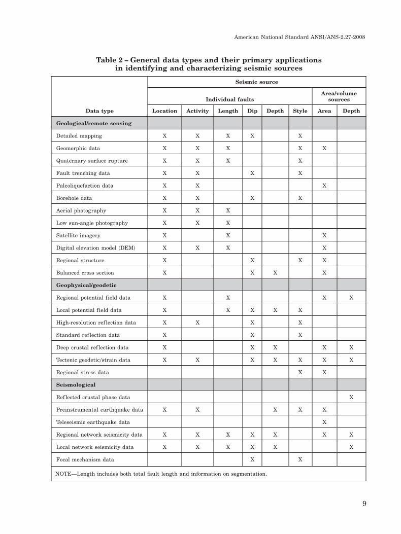
Table 2 – General data types and their primary applicationsin identifying and characterizing seismic sources
Seismic source
Individual faultsArea/volume
sources
Data type Location Activity Length Dip Depth Style Area Depth
Geological/remote sensing
Detailed mapping X X X X X
Geomorphic data X X X X X
Quaternary surface rupture X X X X
Fault trenching data X X X X
Paleoliquefaction data X X X
Borehole data X X X X
Aerial photography X X X
Low sun-angle photography X X X
Satellite imagery X X X
Digital elevation model ~DEM! X X X X
Regional structure X X X X
Balanced cross section X X X X
Geophysical/geodetic
Regional potential field data X X X X
Local potential field data X X X X X
High-resolution ref lection data X X X X
Standard ref lection data X X X
Deep crustal ref lection data X X X X X
Tectonic geodetic0strain data X X X X X X X
Regional stress data X X
Seismological
Ref lected crustal phase data X
Preinstrumental earthquake data X X X X X
Teleseismic earthquake data X
Regional network seismicity data X X X X X X X
Local network seismicity data X X X X X X
Focal mechanism data X X
NOTE—Length includes both total fault length and information on segmentation.
American National Standard ANSI0ANS-2.27-2008
9

Geological, seismological, and geophysical in-vestigations to characterize fault sources shalladdress the uncertainty in the following factors:
~1! Fault location: Quaternary fault tracesshall be defined, and locations shall be shownin map view with sufficient detail to deter-mine source-to-site distance. In the case ofconcealed or blind faults, the location of themost shallow extent of the fault shall be in-dicated on the fault maps.
~2! Fault activity: Recency of activity shallbe assessed for all potential fault sources sig-nificant to the site. Geological, seismologi-cal, geodetic, and geomorphic evidence maybe used to demonstrate fault activity. How-ever, only geological evidence should be usedto demonstrate fault inactivity.
~3! Fault dip and downdip width: To modelfault sources in three dimensions, an assess-ment shall be made of the dip of the faultthroughout the seismogenic crust. The down-dip width of a fault may be assessed indi-rectly based on the estimated maximum depthof the seismogenic crust and the dip of thefault source. Example approaches to evalu-ate the angle of dip are ~a! use of geometry offoreshock0aftershock and background earth-quake foci to constrain fault plane orienta-tion; ~b! seismic ref lection profiles, whereavailable; ~c! balanced geologic cross sec-tions; and ~d! details of outcrop patterns alongrange fronts.
~4! Fault slip rate: In evaluating the rate ofQuaternary fault slip, the following factorsshall be considered: ~a! historical and geo-logical evidence regarding the Quaternarydisplacement history of the fault, ~b! the pre-instrumental and instrumental seismicity data,~c! structural relationships that may indicatekinematic linkages to a known Quaternaryfault, and ~d! the regional tectonic setting. Forfaults where there are no young deposits or astratigraphic record that can be used to as-sess the timing or amount of displacement, alower limit of detection should be assessed, andthe slip rate estimate should encompass theuncertainty in the potential range of values.
~5! Sense of slip (i.e., style of faulting): Thehorizontal and vertical components of dis-placement and fault dip shall be assessed toproperly classify the sense of slip on a fault.
For cases in which a fault has experiencedslip in more than one direction during itshistory, the emphasis should be on assessingits sense of slip in the current tectonic regime.
~6! Concealed and blind faults: The location,dimensions, and rate of slip of concealed andblind faults shall be evaluated. Concealed andblind potential seismic sources can be iden-tified and characterized by a combination ofsubsurface interpretations ~e.g., balanced crosssections, seismic ref lection data! coupled withevidence for geologically young deformation~e.g., folding of Quaternary deposits and sur-faces!, geodetic measurements @e.g., global po-sitioning system ~GPS! and interferometricsynthetic aperture radar surveys# , and seis-micity studies ~e.g., focal mechanism analysis!.
~7! Fault length and segmentation: Faultzones usually consist of individual fault seg-ments. Fault segmentation provides a meansfor estimating the expected length of faultruptures. The total fault length, locations offault segments, and the boundaries betweensegments shall be evaluated.
The following methods are used to identify andcharacterize Quaternary faults:
~1! Review of available geological mapping:Available geological maps that show the lo-cation of faults and identify the ages of geo-logic units displaced by the fault shall becompiled and reviewed. Large-scale geologicmaps ~e.g., 1:24 000 or larger scale! pre-pared within the past 30 years generallyprovide the most reliable information for thistype of assessment. In the process of obtain-ing and reviewing these maps, researcherswho may be actively working on the geologyof the area should be contacted, as needed.Possible sources of information may includeuniversities, consulting firms, and govern-ment agencies.
~2! Analysis of tectonic setting: The tectonicsetting of the site region shall be evaluated.Information on site physiography, topogra-phy, and surface and subsurface geologyshould be presented if relevant to assessingfault location and activity. Geological datashould be used as the basis for discussions ofthe regional and site tectonic framework in-cluding contemporary stress regime, stratig-raphy, structure, seismicity, and geodesy. The
American National Standard ANSI0ANS-2.27-2008
10

distribution of tectonic features ~i.e., faultsand folds! should be depicted on a geologicalmap~s! of appropriate scale. The tectonic analy-sis should include a discussion of tectonicevolution of the site region, with particularemphasis on the timing of inception and na-ture of deformation within the contemporarytectonic setting. Measured or inferred ratesof crustal stress and strain, both vertical andhorizontal, should be considered. The contem-porary tectonic setting of the site should bepresented both in the context of the site re-gion and the larger plate tectonic setting,with emphasis on the patterns and interrela-tionships of regional structure and seismicity.
~3! Detailed geological mapping: Detailedmapping shall be performed where ade-quate data are not available to accuratelylocate the primary and secondary traces ofQuaternary faults that could pose a signifi-cant ground motion or surface-fault rupturehazard and to define fault length and seg-mentation. Mapping also should be consid-ered to identify sites for more detailedgeomorphic analyses and subsurface paleo-seismic investigations ~e.g., trenching or geo-physical surveys! if such studies are required.Geological mapping should include inter-pretation of aerial photography and LiDARdata if available, field investigations, andaerial reconnaissance if needed to confirmor further evaluate geologic features. Strat-igraphic and structural features should bedepicted on a geological map and one ormore cross sections of appropriate scale. Em-phasis should be placed on mapping Quater-nary depositional and erosional events thatconstrain the location, timing, and amountsof current tectonic deformation. Uncertain-ties in each of these parameters should bediscussed.
~4! Detailed geomorphic analyses: In addi-tion to being a tool to identify and mapQuaternary faults, geomorphic analysesshould be used to assess past earthquakebehavior on a fault. Geomorphic features suchas stream channels, stream terraces, allu-vial fan surfaces, marine terraces, and gla-cial moraines, especially those for which thereis some age control, are commonly used toassess fault slip rate, recency of activity,and the direction and amount of displace-ment during an earthquake. Field- and office-
based studies should be conducted todocument fault displacements and to iden-tify locations and rates of Quaternary defor-mation. Attention should be given to theage of geomorphic development of the siteregion and the youngest period of landformrejuvenation. Fault-controlled geomorphic fea-tures shall be discussed in detail with atten-tion given to assessing fault geometry andage of the latest fault movement.
~5! Subsurface investigations: Subsurface in-vestigations often provide the most defini-tive information on fault location and faultbehavior and shall be conducted as neededto identify and characterize faults that couldpose a surface-rupture hazard or significantground motion hazard to the site. Subsur-face investigations include exploratory trench-ing, large- and small-diameter boreholes, andgeophysical prof iling. Boreholes may bedrilled to define the thickness and charac-ter of surficial deposits, or the depth andtype of bedrock. Site-specific geophysical pro-filing ~e.g., seismic ref lection and refractionsurveys designed to image various depth in-tervals, ground-penetrating radar, magneticsurveys, various types of electromagnetic sur-veys! may be employed to identify and pro-vide preliminary characteristics of faults,folds, or fault-related deposits in the subsur-face that do not exhibit substantial grounddisturbance. These profiles may provide crit-ical data on fault location and geometry andshould be used to help choose specific loca-tions for exploratory trenching. Exploratorytrenching is the most commonly used methodfor assessing paleoseismic fault activity andsense of displacement. Sites for trenchingshould be carefully chosen following prelim-inary geological observation and mapping.Preferable sites include those having depo-sition of late Quaternary deposits across thefault trace and minimal episodes of erosion.Continuous deposition is preferred to pro-vide a complete record of fault activity.
~6! Seismicity data: Seismicity data for thesite region shall be compiled and analyzed.The seismicity data catalog should includeall historical ~i.e., preinstrumental! and in-strumental data. Significant historical earth-quakes in the site region should be described.Earthquake focal mechanisms should be com-piled from available sources to aid in the
American National Standard ANSI0ANS-2.27-2008
11
characterization of the tectonic setting of thesite region and area. Analyses of the earth-quake catalog shall include ~a! reducing var-ious measures of earthquake size to a uniformmagnitude measure that is consistent withthe ground motion attenuation relationshipsselected for characterizing ground motion haz-ard at the site and ~b! determining the timeperiod of complete reporting for various mag-nitude levels contained in the catalog. Seis-micity analyses should include a descriptionof magnitude measures and intensities foundin the catalog, statistical relationships andprocedures used to convert the various mea-sures of earthquake size to uniform magni-tude measure, and catalog completeness bymagnitude levels for different time periods.The changing accuracy of epicentral loca-tions with regard to historical and networkearthquake data and the significance andlimitations regarding earthquake focal depthsshould be addressed.
4.1.1.2 Volumetric source zones
Literature reviews shall be conducted to eval-uate the seismotectonic setting of the site re-gion and to identify volumetric source zonesthat are characterized by assumed uniform pat-terns, rates, or styles of deformation and0orseismicity and maximum magnitudes.
Volumetric source zones, which are com-monly referred to as areal or area source zones,represent regions of distributed seismicity thatare not associated with specific known faultsand therefore are considered to be occurringon unidentified and0or unidentifiable faults.Earthquakes in volumetric source zones gen-erally occur at depths of from a few kilo-meters to a few tens of kilometers exceptwithin subducted oceanic crust where seis-mogenic depths can approach hundreds of ki-lometers. Volumetric source zones may be usedto model the occurrence of earthquakes onknown faults or fault zones at great dis-tances from a site when the details of theindividual faults are not significant to thePSHA.
Volumetric source zones shall be defined byboundaries shown on maps of appropriate scaleto differentiate each zone. The depth range overwhich each volumetric source zone is seis-mogenic shall be defined. Volumetric sourcezones range in size from concentrated zones ofseismicity, to regional sources, to background
sources. The boundaries of each volumetricsource zone should be defined to contain re-gions of assumed uniform seismic potential interms of earthquake recurrence and maximumearthquake magnitude. Uncertainty in defin-ing volumetric source zones should be ex-pressed by considering alternative zonations ortreatment of seismicity parameters as outlinedin ANSI0ANS-2.29-2008 @3# ~see Sec. 5.2.2 in@3# !.
The following data shall be used to identifyand characterize volumetric source zones:
~1! Geologic and tectonic data: The distribu-tion of tectonic features ~i.e., faults and folds!,geophysical anomalies, and major tectonic andphysiographic boundaries used to delineatesource zone boundaries shall be depicted ona map of appropriate scale. Key regional orlocal structural features should also be de-picted on one or more cross sections of appro-priate scale.
~2! Paleoseismicity data: Paleoliquefaction andother paleoseismological investigations in-cluding detailed mapping, geomorphic analy-ses, and subsurface investigation of significantseismic sources shall be reviewed and ana-lyzed with regard to location and geometry,maximum magnitude potential, and earth-quake recurrence. Geological reconnaissanceshould be conducted within the site vicinityto evaluate evidence for the presence or ab-sence of paleoliquefaction if geologic condi-tions are favorable for the development andpreservation of a record of strong groundshaking.
~3! Seismicity data: Seismicity data for thesite region shall be compiled and analyzed~see Sec. 4.1.2.1!. Variations in the spatialdistribution, concentration, or density of seis-micity should be used to delineate sourcezones. Changes in focal mechanisms, whichcould indicate changes in the style of fault-ing or stress orientation, also are significantand should be noted.
Documentation of the definition of individualsource zones should include discussions of re-gional and site tectonic framework, includingcontemporary stress regime, and stratigraphicrelationships that constrain the timing and spa-tial distribution of Tertiary and Quaternary de-formation, structure, and seismicity. Discussions
American National Standard ANSI0ANS-2.27-2008
12
shall address the similarities0differences amongthe delineated provinces that bear on the sizeand frequency of future earthquakes. Uncer-tainties in tectonic interpretations that are usedto define alternative locations and geometriesof volumetric source zones shall be discussed.In addition, the expected style of faulting shouldbe evaluated.
4.1.2 Maximum earthquake magnitude
As specified in ANSI0ANS-2.29-2008 @3# , theestimated maximum earthquake magnitudethat a seismic source is capable of generatingin the current tectonic stress regime shall beassessed for each seismic source. The maxi-mum earthquake magnitude defines the up-per bound to the earthquake recurrencerelationship. Approaches used to estimate andassess maximum earthquake magnitudes forfaults and volumetric source zones are de-scribed in Secs. 4.1.2.1 and 4.1.2.2.
4.1.2.1 Maximum earthquakemagnitude: Faults
Assessments of maximum magnitudes for faultsources should include constraints provided byseismicity data and constraints provided by es-timates of maximum dimensions of rupture.
In most cases, the historical earthquake recordfor individual faults is far shorter than therecurrence intervals for the largest earth-quakes, and the probability that the historicalrecord includes the maximum event is small.However, if the historical record includes a sig-nificant earthquake that can be associated withthe fault, it should be assessed as either a lowerbound or a best estimate of the maximum mag-nitude. In cases where the historical event wasassociated with coseismic rupture, the extentof that rupture should be evaluated in the con-text of the maximum rupture dimensions of thefault.
Earthquake magnitude and rupture dimen-sions are correlated. It follows that if rupturedimensions associated with a maximum earth-quake on a fault can be estimated, the maxi-mum magnitude should be assessed. Commonly,a number of potential rupture dimensions canbe estimated ~e.g., rupture length, rupture area,displacement per event!, and a magnitudeshould be estimated for each. Paleoseismic dataregarding the number of events and rupturedimensions are usually associated with consid-
erable uncertainty. Uncertainties in the esti-mates of fault rupture parameters resulting fromambiguous data, lack of deposits of suitableage to evaluate location, timing, amount, andcontinuity of extent of Quaternary faulting,should be documented.
Fault rupture parameters that have beenshown empirically to be correlated with earth-quake magnitude include rupture length, rup-ture area, maximum surface displacement,and average surface displacement @13,14#. Theevaluation of these parameters for an indi-vidual fault includes paleoseismic investiga-tions of the extent and variations of slip alongstrike of past ruptures.
4.1.2.2 Maximum earthquakemagnitude: Volumetric source zones
The assessment of maximum earthquake mag-nitudes for volumetric source zones is particu-larly difficult because the physical constraintmost important to the assessment, the dimen-sions of fault rupture, typically is not known.As a result, the primary methods for assessingmaximum earthquakes for volumetric sourcezones should include a consideration of the his-torical seismicity record, paleoseismic evidenceof past earthquakes, and analogies to othersources in similar tectonic environments.
Studies of the sizes of historical earthquakesassociated with the volumetric source zone ofinterest should be made. It is possible that af-ter the historical record has been examined, itwill be concluded that the record provides noparticular constraint on the estimate of maxi-mum earthquake for the source. Alternatively,the maximum historical earthquake for the zonemay be assessed as either a lower bound orbest estimate of the maximum magnitude forthe source.
In cases where the largest historical earth-quake is judged to not be the maximum earth-quake, the use of a specified incremental unitlarger than the historical earthquake shouldbe avoided if other database alternatives exist.For example, studies of the distribution andsizes of seismic-induced features such as pale-oliquefaction features can provide indicationsof the sizes of prehistoric earthquakes, and pub-lished information regarding such featuresshould be used in estimating the sizes of max-imum earthquakes. Field studies to evaluatethe presence or absence of such features in the
American National Standard ANSI0ANS-2.27-2008
13
site vicinity or region may provide additionaldata to constrain the size of the maximummagnitude.
Other considerations in assessing maximumearthquakes for volumetric source zones areanalogies to other sources. The source of inter-est may be tectonically similar to another sourcesuch that their maximum earthquakes also areconsidered similar.
A project by the Electric Power Research In-stitute ~EPRI! specifically addressed prob-lems of estimating maximum earthquakemagnitude in stable continental regions usingthis approach. As part of this project, Johnstonet al. ~1994! @15# developed worldwide data-bases that can be used to estimate maximumearthquake magnitude for seismic sources inthe CEUS.
Considerations of possible rupture dimensionsalso may be used in the assessment of maxi-mum magnitudes for volumetric source zones.For example, the lengths of zones of concen-trated seismicity or the dimensions of tectonicelements within a source zone may be assessedto represent maximum rupture dimensions.
4.1.3 Earthquake recurrence
As specified in ANSI0ANS-2.29-2008 @3# , earth-quake recurrence relationships that quantifythe frequency of different magnitude earth-quakes shall be assessed for each seismic source.Different approaches commonly are used to as-sess earthquake recurrence for fault sourcesand volumetric source zones, as described inSecs. 4.1.3.1 and 4.1.3.2.
4.1.3.1 Earthquake recurrence: Faults
Most faults have not ruptured even once, letalone repeatedly, during the historical period.Therefore, estimates of earthquake recurrenceshould be developed from a variety of ap-proaches. The most direct approach is to datesuccessive faulting events through paleoseis-mological trenching studies and fault geomor-phic investigations. These studies can provideinformation on the actual intervals, along withuncertainties, between earthquakes on faultsthat directly rupture or deform ~i.e., uplift orfold in the case of blind faults! the surface.Available paleoseismological data should be usedto develop a fault-specific earthquake recur-rence model that includes the magnitude of
the event that produced the surface faultingor deformation.
Another approach is to use a geologically de-termined fault slip rate and an estimate of ex-pected average displacement per event tocalculate an average recurrence interval andits variability. However, as earthquake recur-rence is more widely studied on faults in avariety of tectonic settings, it is clear that thereis a spectrum of recurrence behavior that rangesfrom quasi-uniform to highly nonuniform. Evi-dence for spatial or temporal clustering of earth-quakes should be noted. This requires thataverage recurrence estimates on faults be putinto a long-term and regional framework.
4.1.3.2 Earthquake recurrence:Volumetric source zones
In many regions, particularly the CEUS, it isoften difficult to identify the specific locationsof seismogenic faults. In these areas, fault-specific paleoseismologic investigations such asthose noted in Sec. 4.1.3.1 are not appropriate,and the following types of observations and datashould be considered to develop information onearthquake recurrence:
~1! Paleoliquefaction data: The use and eval-uation of shaking-induced permanent grounddeformation features ~e.g., paleoliquefaction!may provide information on the recurrenceof ground motions that can affect a site;
~2! Seismicity data: Recurrence relation-ships should be developed from historical andinstrumental seismicity with due regard forthe statistical variability in these estimates;
~3! Geodetic data: With the emergence of GPSnetworks throughout the country, informa-tion on rates of strain accumulation is becom-ing increasingly available. Analysis of GPSconstraints on regional strain rates, particu-larly in combination with seismicity data,should be undertaken to develop earthquakerecurrence estimates for these source types.Use of these data should address limitationsin the data that stem from the length of theGPS record and stability of the network sta-tions. These data should also be comparedwith long-term geologically derived slip ratesand deformation rates inferred from seismic-ity data to ensure that the inferred rates arereasonable.
American National Standard ANSI0ANS-2.27-2008
14
Two alternative approaches may be used tocharacterize the spatial distribution of futureearthquakes within the regional zones. Thefirst approach considers that there is equallikelihood of occurrence of earthquakes at alllocations within the source zone. An alterna-tive interpretation that may be applied is non-uniform spatial occurrence expressed by anonuniform spatial density function for thevolumetric source zone using the recorded seis-micity kernel density. This interpretation im-plies that future seismicity is more likely tooccur near where it has in the past. Thisinterpretation was used to develop the na-tional seismic hazard maps for the UnitedStates @16,17,18# . More specific guidelinesfor developing recurrence parameters for seis-mic sources are provided in ANSI0ANS-2.29-2008 @3# .
4.2 Fault rupture hazardcharacterization
The potential for surface fault rupture and as-sociated deformation shall be determined. Thisassessment shall include the evaluation of bothprimary faults that reach the ground surfaceas well as secondary ground deformation ~e.g.,faulting, folding, tilting, warping, etc.! relatedto concealed or blind faults that do not reachthe ground surface.
The investigation of a site and its vicinity forsurface faulting shall include the following:
~1! examination for potential Quaternary sur-face faults at the site or for Quaternary faultsthat trend toward the site;
~2! evaluation of the activity and origin ofany Quaternary faults detected at the site orin the site vicinity that trend toward the siteand the history of their displacement by theuse of appropriate and accepted techniquesand methods @19,20#;
~3! evaluation of the width of the Quater-nary fault zone, including areas of possiblesecondary ground deformation.
The types of studies and areas of investiga-tion needed to evaluate the potential for sur-face rupture hazard depend on the tectonic,geological, and seismological setting of the site.The assessment of surface rupture hazard re-quires much of the same information de-scribed in Sec. 4.1.2.1 needed to characterizefault sources for seismic source models ~i.e.,timing of most recent movement and rate of
activity, location, geometry, sense of displace-ment, recurrence or rate of deformation, andmaximum size or displacement per event!. Theassessment should include all or parts of thefollowing studies: ~a! literature and data re-view; ~b! aerial reconnaissance and aerial photointerpretation; ~c! reconnaissance and detailedgeological and geomorphic mapping; and ~d!analysis of historical ~preinstrumental! and in-strumental seismicity, hydrological, geophysi-cal, geological, and geodetic data.
Surface fault rupture may result from eithertectonic or nontectonic phenomena. Hansonet al. ~1999! @19# discuss criteria for differen-tiating tectonic from nontectonic faults. Non-tectonic faults may have similar physicalcharacteristics as tectonic faults, but they arevery different in terms of origin and poten-tial hazard. The identification and character-ization of surface fault rupture hazards requirethe ability to distinguish among tectonicallyinduced faulting, faulting induced by strongground motions, and faulting caused by non-tectonic phenomena. Tectonic faults includeboth structures capable of producing earth-quakes and secondary structures that are pro-duced by earthquakes but are not themselvescapable of generating an earthquake. Exam-ples of secondary tectonic faults includehanging-wall deformation above a concealedthrust fault and various types of strong groundmotion phenomena ~e.g., ridge-crest shatter-ing, basin-margin fracturing, etc.!. Nontec-tonic phenomena that can result in surfacedeformation at a facility site, but are not ca-pable of producing significant earthquakesand vibratory ground motion ~i.e., are non-seismogenic!, include those produced by grav-itational processes ~e.g., landslide features,etc.!, dissolution phenomena, subsidence dueto extensive f luid extraction, sediment load-ing and dewatering ~e.g., soft-sediment defor-mation!, evaporite migration ~e.g., salt domeand salt f lowage structures!, sediment com-paction ~e.g., growth faults, subsidence struc-tures, etc.!, glaciers ~e.g., ice push features!,and glacio-isostatic rebound ~e.g., popups!.
Results of site investigations shall provide doc-umentation of the presence or absence of sur-face fault rupture hazards at the site. Where itis determined that surface fault rupture haz-ards are not present, sufficient data and dis-cussion to clearly justify this determination shallbe presented. In cases where engineered de-sign for fault displacement or engineered
American National Standard ANSI0ANS-2.27-2008
15

stabilization measures are feasible, sufficientdata regarding the mechanism, location, tim-ing, and scale of deformation shall be providedto evaluate design options.
4.3 Geotechnical investigations
The geotechnical investigations should include,but not necessarily be limited to,
~1! defining site soil and near-surface geo-logic strata properties as may be requiredfor hazard evaluations, engineering analy-ses, and seismic design;
~2! evaluating the effects of local soil andsite geologic strata on ground motion at theground surface;
~3! evaluating dynamic properties of the near-surface soils and geologic strata;
~4! conducting soil-structure–interaction ~SSI!analyses;
~5! assessing the potential for soil failure ordeformation induced by ground shaking ~liq-uefaction, differential compaction, and land-sliding!.
4.3.1 Information review and sitereconnaissance
Review of available information, includingresults of previous investigations, and sitereconnaissance shall be performed to sup-port subsurface investigations, laboratory test-ing, and engineering analyses described inSecs. 4.3.2.1, 4.3.2.2, and 4.4, respectively. Thisinformation is essential for understanding thegeneral geological and geotechnical conditionsof the site, so that the later phases of geotech-nical investigations can be effectively and ef-ficiently planned. This information also providesa framework in which new data can be prop-erly evaluated and applied to the design andevaluation of the foundations and assessmentof potential site geotechnical hazards.
Available information may include
~1! topographical, geological, geophysical, hy-drogeological, and soil survey maps;
~2! aerial photographs and other remote-sensing imagery;
~3! geological and geotechnical reports andother related literature;
~4! well records and hydrological data;
~5! historical records and Quaternary geolog-ical evidence of landslides, f loods, earth-quakes, subsidence, liquefaction, and otherevents of geologic or geotechnical significance;
~6! past geotechnical performance of the siteand other sites and structures in the sitevicinity.
Site reconnaissance activities should include
~1! mapping of topographical, hydrological,and surface geological features;
~2! identifying rock outcrops, soil conditions,evidence of past landslides or soil liquefac-tion, faults, fracture traces, and geologicalcontacts;
~3! detailed on-site mapping of local engineer-ing geology and soils.
4.3.2 Site investigations
Site investigations shall be conducted as neededto characterize the geotechnical conditions atthe site commensurate with the seismic designrequirements of the facility ~see Sec. 4.3.2.1!.Geologic profile, stratification, and quantifica-tion of site soil0rock properties are needed forengineering design and evaluations of soil am-plification, SSI, potential for liquefaction, dif-ferential settlement, and landslides.
An appropriate site investigation program shallbe developed in consultation with a qualifiedgeotechnical engineering representative of theproject team.
Soil0rock profiles ~i.e., cross sections! at thelocations of the facilities shall be provided basedon the results of site investigations.
Static properties of the soils and rocks areused to help characterize the site subsurfaceconditions and in analyses and design ofgeotechnical aspects of engineered struc-tures at the site. Index and classificationproperties typically include moisture con-tent, unit weight, grain-size distribution, plas-ticity, specif ic gravity, relative density,porosity, and rock quality designation ~RQD!.Engineering properties typically include com-pressive and tensile strengths, shear strengthcharacteristics, compressibility, overconsoli-dation ratio, lateral earth pressure coeffi-cients, compaction, permeability, swellingpotential, elastic constants, and creep param-eters. Other properties, such as electricalresistivity and gamma logging, may be rele-
American National Standard ANSI0ANS-2.27-2008
16
vant, as well, depending on the site, andshould be considered for use in the evaluation.
Dynamic properties of the soils and rocks areused to study ground motion amplification,SSI, liquefaction potential, seismic slope sta-bility and deformation, and foundation move-ments of nuclear facilities caused by seismicevents. Dynamic properties typically includewave velocities ~i.e., compression and shear!,strain-dependent shear modulus and damp-ing, cyclic shear resistance, and rate of load-ing effects on strength and modulus properties.
4.3.2.1 Subsurface exploration
Subsurface conditions shall be determined usingmethods appropriate for the site conditions, in-cluding borings, penetration resistance @e.g.,standard penetration test ~SPT!, cone penetra-tion test ~CPT!, and Becker penetration test~BPT!# , soundings, well logs, exploratory exca-vations, sampling, and geophysical methods @e.g.,cross-hole, downhole, spectral analysis of sur-face waves ~SASW!, and geophysical logging# ,that adequately characterize soil and ground-water conditions.
Appropriate investigations shall be made to de-termine the contribution of the subsurface soilsand rocks to the loads imposed on and dynamicresponse of the structures subjected to seismic-induced strong ground motion.
Representative samples of soils and rocksshould be obtained for classification and test-ing. The QA requirements shall address issuesassociated with retrieval, transportation, han-dling, and testing of soil samples. Sufficientgeophysical and geotechnical data shall be ob-tained to allow reasonable assessments of rep-resentative soil profiles and parameters as wellas their variability. The nature and extent ofsubsurface exploration shall be dictated by theSDC of the facilities and the desired level ofconfidence in the results, by the foundationrequirements, and by the complexity of theanticipated subsurface conditions. The loca-tions and spacing of borings, soundings, andexploratory excavations shall be chosen to ad-equately characterize subsurface conditions, in-cluding their uncertainties, and shall be locatedto permit the construction of geological crosssections and soil profiles needed for seismicsite response studies and for design of foun-dations of safety-related structures and otherimportant facilities at the site. Subsurface ex-
ploration generally employs borehole drillingand sampling and cone penetrometers. Proce-dures used for such exploration should complywith the applicable American Society for Test-ing and Materials ~ASTM! standards or proce-dures acceptable to the regulatory agencyproviding oversight for the project.
A number of samples sufficient to permit lab-oratory determination of average propertiesand to indicate their variations are neces-sary. The appropriate number and depth ofsamples should be determined by the judg-ment of a qualified geotechnical engineer fromthe subsurface conditions revealed during fieldexploration and commensurate with the SDCclassification of the facilities. The detailedscope of the program needs to be able to ad-dress all seismic issues ~site response, SSIeffects, foundation issues, and dynamic de-mands on the facilities and housed SSCs! ofinterest in the design.
Recommendations for site investigation for re-actor facilities are presented in NRC Regula-tory Guide 1.132 ~2003! @21# that can beconsidered appropriate for facilities classifiedas SDC-5. NUREG0CR-5738 @22# provides ad-ditional methods for field investigations forfoundations of nuclear power facilities. Thenumber, spacing, and depth of site penetra-tions ~borings, cone penetrometers!; numberand type of soil samples obtained; and associ-ated testing program may be relaxed for eval-uations of facilities of lower SDC classification.For example, for SDC-3 facilities subjected torelatively low levels of seismic demand, dy-namic laboratory testing to obtain strain-dependent shear modulus and dampingproperties may not be necessary, and genericpublished relations for similar type soils maybe used in their place. The depth of investiga-tion needed for SSI evaluations, typically con-sidered to be twice the smallest dimension ofthe facility, may similarly be relaxed for eval-uation of SSI effects of facilities of lower seis-mic classification. However, information on theshallow profile ~layering, shear velocity con-trasts, etc.! known to be important to SSI re-sponse should be incorporated into thesubsurface characterization program for all nu-clear facilities of category SDC-3 and higher.
Disturbed samples are typically taken at reg-ular intervals ~e.g., 5 ft!, at every change instrata, or continuously if a specific conditionor hazard ~e.g., liquefaction! is being as-sessed. They are primarily used for classifi-cation tests and must contain all of the
American National Standard ANSI0ANS-2.27-2008
17
constituents of the soil even though the soilstructure is disturbed. Undisturbed samples,if deemed to be required to develop strengthand stiffness properties, should be taken atspecific depths or continuously depending onthe design problems, testing program, andsubsurface materials encountered. In obtain-ing disturbed and undisturbed samples, pen-etration resistance data should be monitoredand recorded.
The material properties obtained from thesoil and rock samples may not adequatelyrepresent in situ properties, due to the diffi-culties in duplicating the subsurface condi-tions in the laboratory. If the available dataare not sufficient, in situ measurements andtests should be conducted to obtain the un-disturbed, in situ material properties in thefield. Such in situ measurements may beobtained using CPT soundings, and0or fieldvane, dilatometer, pressuremeter, or geophys-ical methodologies.
In situ measurements of wave velocities maybe obtained using several methods, each ofwhich has particular strengths depending onthe site characteristics @23#. Cross-hole, down-hole, and seismic cone techniques provideuseful direct measurements of wave veloci-ties in soil and rock boreholes. Because higherfrequencies are used in the suspension log-ger ~i.e., 102 kHz!, some soil media requirea correction to compare with results of othergeophysical techniques. SASW is a usefultechnique for determining shear wave veloc-ities at sites where expected subsurface con-ditions warrant its application. No consistentlyreliable technique has been developed to in-fer low-strain damping. Where justified, mul-tiple methods of geophysical testing shouldbe used to generate confidence in inferredsite properties.
Groundwater conditions have significant impli-cations for assessing seismic-induced hazardsand shall be assessed at each nuclear facilitysite. Groundwater conditions normally are ob-served in borings at the time they are drilled.The groundwater level should be measured atthe start of each workday for borings in progress,at the completion of drilling, and when thewater levels in the borings have stabilized. It isnoted that when drilling mud is used in a bor-ing, accurate groundwater levels generally arenot obtained. For these cases, or if significantseasonal f luctuation of groundwater level isanticipated, groundwater observations should
be made by means of properly installed wellsor piezometers that are read at regular inter-vals to assess the groundwater f luctuations as-sociated with seasons and changes in surfacewater conditions. Piezometers can be installedto independently measure the piezometric pres-sures of different hydrological units, such asperched or artesian groundwater conditions.Types of piezometers and observation wells andrecommended methods for their installation andmaintenance are described in Dunnicliff ~1988!@24# and the U.S. Army Corps of Engineers~1995! @25# .
4.3.2.2 Laboratory testing
A laboratory testing program shall be carriedout to identify and classify the subsurface soilsand rocks and to help characterize their phys-ical and engineering properties if such infor-mation is not available for the site. Laboratorytests for both static properties ~e.g., shearstrength, compressibility! and dynamic proper-ties ~e.g., shear modulus, damping, cyclic shearresistance! generally are required. Both staticand dynamic tests shall be conducted in accor-dance with applicable ASTM standards or testprocedures acceptable to the regulatory agencyproviding oversight to the project. The ASTMspecification numbers for static and dynamiclaboratory tests can be found in Annual Bookof ASTM Standards, Volume 04.08. Sufficientlaboratory test data should be obtained to al-low reliable assessments of central tendencyand distribution values of soil properties andtheir variability. Guidance for testing require-ments for critical facilities is presented in NRCRegulatory Guide 1.138 @26# .
Soil and rock samples for laboratory testingshall be selected after careful examination ofboring records and available samples. It is im-portant that test specimens be representativeof the soil or rock unit to be tested and beaccurately described to permit establishmentof the stratigraphic profile. Samples should betested as soon after reaching the laboratory aspossible to minimize the effects of structuraland chemical changes with time. Undisturbedtube samples of soils should be examined forevidence of disturbance. Radiographs shouldbe used to determine the quality of soil sam-ples, effects of sampling disturbances, and thepresence of naturally occurring anomalies. Gen-
American National Standard ANSI0ANS-2.27-2008
18
erally, tests on samples of mixed or stratifiedmaterial should be avoided. It is very impor-tant to avoid or minimize disturbance of soilstructure and changes of moisture during sam-ple removal from tubes and trimming and shap-ing of specimens. Reconstituted or remoldedsamples are used when representative undis-turbed samples cannot be obtained or whenthey are used as representative compacted fillor backfill materials. Undisturbed samples offill should be taken for confirmatory testingduring construction. Reconstituted and re-molded samples should ref lect the densities andmoisture contents measured or anticipated un-der field conditions.
For coarse geological materials such as coarsegravels and sand-gravel mixtures, special test-ing equipment and testing facilities may beused, if deemed necessary. Larger sample sizeis required for laboratory tests on this type ofmaterial. It is generally difficult to obtain un-disturbed samples of unconsolidated gravellysoils for laboratory tests. If it is not feasible tocollect test samples and, thus, no laboratorytest results are available, the dynamic proper-ties should be estimated from the publisheddata of similar gravelly soils and0or character-ized based on in situ geophysical methods.
The dynamic sampling and testing programshould be carefully planned to consider the depthrange over which suitable undisturbed samplescan be obtained and to characterize the mate-rial properties under the stress and strain con-ditions expected during the natural phenomenaevents. The program should evaluate the ef-fects of the events on both static and dynamicproperties. The following factors should be con-sidered in determining the dynamic propertiesof soils:
~1! conditions of undisturbed test speci-mens, especially cohesionless materials;
~2! method of sample preparation;
~3! consolidation and saturation of specimens;
~4! wave form of cyclic loading ~Note: sinu-soidal loading is most frequently used!;
~5! frequency of loading;
~6! duration of applied consolidation pressure.
ASTM standards give detailed procedures thatare widely accepted and utilized for testing ofindex and engineering properties of soils androcks. In addition, the International Societyof Rock Mechanics provides commonly ac-cepted methods for various rock property tests.Index properties tests include moisture con-tent, unit weight, particle-size analysis, At-terberg limits, specific gravity, relative density,porosity, and RQD. Engineering propertiestests include consolidation, unconfined com-pression, triaxial compression, direct shear,compaction, permeability, swelling potential,tensile strength, and creep tests. Field rockfracturing conditions should be consideredwhen trying to relate field geophysical prop-erties to laboratory data measured on smallsamples.
Dynamic shear modulus and damping valuesof soils are strain dependent. If anticipatedstrain levels are deemed high enough, straindependency effects may be obtained from testscovering the range of strains to be consideredin the design and evaluation. Several labora-tory techniques are available to measure shearmodulus and damping as functions of shearstrain @23# . The measurement techniques areresonant column, cyclic triaxial, cyclic simpleshear, and cyclic torsional shear. These mea-surements typically extend over different butoverlapping strain ranges and use differentexcitation frequencies. The cyclic torsionalshear and resonant column tests are the mostwidely used test methods for determining thestrain-dependent shear modulus degradationand hysteretic damping of soils. Recom-mended test procedures for modulus anddamping of soils are provided in applicableASTM standards.
4.4 Characterization for site responseanalysis
As outlined in ANSI0ANS-2.29-2008 @3# , thequantification of earthquake ground motionsat a facility site shall include an assessment ofsite response effects on ground motions. Theparameters for the site response analysis in-clude descriptions of soil type, subsurface layergeometry and thickness, low strain P-wave andS-wave velocities, and density, in addition tostrain-dependent dynamic shear modulus deg-radation and hysteretic damping ratio rela-tions for each of the soil or soft-rock layers.Uncertainties in these material properties shallbe assessed for determination of mean esti-mates of site response.
American National Standard ANSI0ANS-2.27-2008
19
The characterization of subsurface layer geom-etry shall be sufficient to determine whether aone-dimensional ~i.e., f lat-layer! idealization ofthe site is adequate or whether two- or three-dimensional effects on site response shall bemodeled. Internal friction angle, undrainedshear strength, and overconsolidation ratio forclay could also be needed for nonlinear analyses.
The soil0rock column properties specified shouldideally be characterized to the depth at whichthe subsurface materials reach the shear wavevelocity of “outcrop” materials for which theattenuation relations used in development ofthe PSHA are directly applicable.
The available site-specific data and other per-tinent data as collected from the review of avail-able site information ~e.g., seismic ref lectionand refraction surveys and geotechnical data!shall be used to develop a site response model.The preliminary site data may be adequate toestimate wave velocities, approximate depthsof hard rock, and soil or soft-rock dynamicproperties.
If upon review of available site-specific seis-mic, geotechnical, and geological data there isnot sufficient information to develop a site re-sponse model, a supplemental geophysical andgeotechnical field data acquisition program shallbe developed. The program should take intoaccount the sensitivity of the preliminary soilresponse analysis results to the range of possi-ble input soil parameters. The program shouldfocus on the most uncertain geotechnical pa-rameters that control site response at the fre-quencies of most interest to facility structuraland component response. Peer review shouldbe used to establish whether a supplementalfield program is needed.
If additional data on wave velocities and strain-dependent dynamic material properties are col-lected to obtain sufficient information to developa site response model, those measurements shallbe site specific. The field investigation planshall be peer reviewed. Peer review should payparticular attention to the quality, reliability,and age of the available geophysical or geotech-nical work conducted. Once additional data areobtained and interpreted, they shall be incor-porated with the previously available site in-formation in an updated site response model.
4.5 Site characterization for groundfailure hazard
Ground failure hazard phenomena that couldresult in surface deformation at a facility siteinclude liquefaction of soils, ground settle-ment, and slope failure. Differential groundmovements potentially associated with theseground failure phenomena are a damage haz-ard to facilities at the site. Sufficient investi-gations shall be performed to assess anddocument the presence or absence of each ofthese hazards. Investigations of ground fail-ure hazard due to surface and concealed faultrupture are specified in Sec. 4.2.
4.5.1 Liquefaction of soils
Liquefaction is a soil behavior phenomenon inwhich a soil deposit situated below the ground-water table loses a substantial amount ofstrength due to the development of high ex-cess pore water pressures generated and ac-cumulated in the soil during ground shakinginduced by strong earthquakes or water waveactions. Recently deposited ~i.e., geologicallyyoung! and generally loose natural soils anduncompacted or poorly compacted fills are po-tentially susceptible to liquefaction. Loose sandsand silty sands are particularly susceptible, andloose silts and gravels are susceptible as well.Dense natural soils, aged soils, and well-compacted fills generally have low susceptibil-ity to liquefaction. General procedures forevaluating liquefaction potential, which arebrief ly described below, are given in NRC Reg-ulatory Guide 1.198 ~2003! @27# , Youd et al.~2001! @28# , and Seed et al. ~2003! @29# .
Investigations of potential liquefaction and re-lated effects typically involve both geologicaland geotechnical engineering assessments. Thefollowing site-specific data shall be acquiredand utilized with the evaluation procedures @30#:
~1! depositional and stress history and geo-logic age of the sediments;
~2! soil grain size distribution and density;
~3! groundwater conditions;
~4! penetration resistance of the soil ~e.g.,SPT, CPT, and BPT!;
~5! shear wave velocity of the soil;
~6! evidence of liquefaction or nonoccurrenceof liquefaction during historic seismic events.
American National Standard ANSI0ANS-2.27-2008
20
The most commonly utilized approach is thesimplified empirical procedure that utilizesSPT blow count data. This procedure is basedon the empirical correlation between cyclicstress ratio that is computed from peak groundacceleration ~PGA! and SPT ~N1!60 blow countdata that differentiates the observed occur-rence or nonoccurrence of liquefaction in sanddeposits during earthquakes. The basic cor-relation was developed for magnitude 7.5earthquakes for materials with different finescontents. The correlation may be adjusted toother magnitude events using correctionfactors.
CPT data are also utilized with this approachby conversion to equivalent SPT blow counts,using correlations developed among cone tipresistance, friction ratio, and soil type. Directcorrelations of CPT data with liquefaction po-tential have also been developed.
Alternative approaches, such as the evaluationof threshold strains @31# and probabilistic eval-uations of site data @28#, are available and maybe considered to assess liquefaction potential ofa site.
Liquefaction potential for a soil stratum shouldalso be evaluated through the use of laboratorytesting, by comparing the dynamic0cyclic shearresistance of the soil to the dynamic shear load-ing induced by the natural phenomenon haz-ards event. Laboratory tests for evaluating shearand other deformation behavior for soils arediscussed in Sec. 4.3.2.2.
A soil behavior phenomenon similar to lique-faction is strength reduction in sensitive clays.Although this behavior phenomenon is muchless common than liquefaction, it should not beoverlooked as a potential cause for landslidingand lateral movements @32# . Therefore, the ex-istence of sensitive clays at the site shall beevaluated.
4.5.2 Ground settlement
Ground settlement due to dynamic loads, changeof groundwater conditions, soil expansion, soilcollapse, erosion, and other causes shall be con-sidered. Ground settlement due to ground shak-ing can be caused by two factors: ~a! compactionof dry or partially saturated sands due to groundshaking and ~b! settlement due to dissipationof dynamically induced pore water pressure insaturated sands. Differential compaction of co-hesionless soils and resulting differential ground
settlement could accompany liquefaction or couldoccur in the absence of liquefaction. The sametypes of geological information and soil dataused in liquefaction potential assessmentsshould be used in assessing the potential forseismic-induced ground settlement.
Simplif ied procedures such as those pre-sented by Tokimatsu and Seed ~1987! @33#and Ishihara and Yoshimine ~1992! @34# areavailable to assess potential earthquake-related settlements. Cyclic0dynamic labora-tory testing with postliquefaction or postcyclicvolumetric strain measurements may also beused to help assess settlement hazard.
Ground subsidence has been observed at thesurface above shallow cavities formed by natu-ral processes and by human activities includ-ing mining ~particularly coal mining! andextraction of large quantities of salt, oil, gas, orgroundwater @35# . Where these conditions ex-ist near a site, consideration and investigationshall be given to the possibility that surfacesubsidence will occur.
4.5.3 Slope failure
Stability of natural and man-made slopes shallbe evaluated when their failures could affectthe safety and operation of nuclear facilities.In addition to landsliding facilitated byliquefaction-induced strength reduction ~i.e., lat-eral spreading and0or f low sliding!, instabilityand deformation of hillside and embankmentslopes can occur due to static and dynamicforces. Previous landslides, layers or zones ofweak subsurface materials, strength reductionof the materials caused by liquefaction or bywetting, hydrological conditions including porepressure and seepage, and loading conditionsimposed by other natural phenomenon eventsshall be considered in determining the poten-tial for instability and deformation.
The following information, at a minimum, shallbe collected for the evaluation of slope instability:
~1! slope cross sections covering areas thatwould be affected by slope instability;
~2! soil and rock profiles within the slopecross sections;
~3! static and dynamic soil and rock proper-ties, including densities, strengths, anddeformabilities;
American National Standard ANSI0ANS-2.27-2008
21
~4! hydrological conditions and theirvariations;
~5! rock-fall events.
Various possible modes of failure shall be con-sidered. When a slope-failure hazard exists, bothstatic and dynamic analyses shall be per-formed for the stability of the slopes. Potentialslope movements due to gravity or seismic in-ertial forces shall be evaluated using pseudo-static limit equilibrium stability analyses anddeformation evaluations @36,37# , or more so-phisticated equivalent-linear analyses or fullynonlinear analyses @38,39# .
5 References
The user is advised to review each of the fol-lowing references to determine whether it, amore recent version, or a replacement docu-ment is the most pertinent for each applica-tion. When alternate documents are used, theuser is advised to document this decision andits basis.
@1# ANSI0ANS-2.26-2004, “Categorization ofNuclear Facility Structures, Systems, andComponents for Seismic Design,” Ameri-can Nuclear Society, La Grange Park,Illinois.
@2# ASCE0SEI 43-05, “Seismic Design Crite-ria for Structures, Systems, and Compo-nents in Nuclear Facilities,” AmericanSociety of Civil Engineers, Structural En-gineering Institute, Reston, Virginia.
@3# ANSI0ANS-2.29-2008, “Probabilistic Seis-mic Hazards Analysis,” American Nu-clear Society, La Grange Park, Illinois.
@4# 2006 International Building Code�, Inter-national Code Council ~2006!.
@5# ASCE0SEI 7-05, “Minimum Design Loadsfor Buildings and Other Structures,”American Society of Civil Engineers,Structural Engineering Institute, Res-ton, Virginia.
@6# R. J. Budnitz, D. M. Boore, G. Aposto-lakis, L. S. Cluff, K. J. Coppersmith, C. A.Cornell, and P. A. Morris, “Recommen-dations for Probabilistic Seismic HazardAnalysis: Guidance on Uncertainty and
Use of Experts,” NUREG0CR-6372, UCRL-ID-122160, Lawrence Livermore NationalLaboratory ~1997!.
@7# Regulatory Guide 1.165, “Identificationand Characterization of Seismic Sourcesand Determination of Safe ShutdownEarthquake Ground Motion,” U.S. Nu-clear Regulatory Commission ~Mar. 1997!.
@8# Regulatory Guide 3.73, “Site Evaluationsand Design Earthquake Ground Motionfor Dry Cask Independent Spent FuelStorage and Monitored Retrievable Stor-age Installations,” U.S. Nuclear Regula-tory Commission ~Oct. 2003!.
@9# Regulatory Guide 1.208, “A Performance-Based Approach to Define the Site-SpecificEarthquake Ground Motion,” U.S. Nu-clear Regulatory Commission ~Mar. 2007!.
@10# L. Reiter, Earthquake Hazard Analysis,Columbia University Press, New York~1990!.
@11# R. K. McGuire, Seismic Hazard and RiskAnalysis, p. 221, Earthquake Engineer-ing Research Institute ~2004!.
@12# “NEHRP Recommended Provisions forSeismic Regulations for New Buildingsand Other Structures ~FEMA 450!,” Build-ing Seismic Safety Council of the Na-tional Institute of Building Sciences~2003!.
@13# D. L. Wells and K. J. Coppersmith, “NewEmpirical Relationships Among Magni-tude, Rupture Length, Rupture Width,Rupture Area, and Surface Displace-ment,” Bull. Seismol. Soc. Am., 74, 621~1994!.
@14# T. C. Hanks and W. H. Bakun, “A Bilin-ear Source-Scaling Model for M log A Ob-servations of Continental Earthquakes,”Bull. Seismol. Soc. Am., 92, 1841 ~2002!.
@15# A. C. Johnston, K. J. Coppersmith, L. R.Kanter, and C. A. Cornell, “The Earth-quakes of Stable Continental Regions, Vol-ume 1—Assessment of Large EarthquakePotential,” TR-102261-VI, Electric PowerResearch Institute ~1994!.
American National Standard ANSI0ANS-2.27-2008
22

@16# A. Frankel, “Mapping Seismic Hazard inthe Central and Eastern United States,”Seismol. Res. Lett., 66, 8 ~1995!.
@17# A. Frankel, C. Mueller, T. Barnhard, D.Perkins, E. V. Leyendecker, N. Dickman,S. Hanson, and M. Hopper, United StatesNational Seismic Hazard Maps, Open FileReport 96-532, U.S. Geological Survey~1996!.
@18# A. D. Frankel, M. D. Petersen, C. S. Muel-ler, K. M. Haller, R. L. Wheeler, E. V.Leyendecker, R. L. Wesson, S. C. Harm-sen, C. H. Cramer, D. M. Perkins, andK. S. Rukstales, United States NationalSeismic Hazard Maps, Open File Report02-420, p. 33, U.S. Geological Survey~2002!.
@19# K. L. Hanson, K. I. Kelson, M. A. Angell,and W. R. Lettis, “Techniques for Identi-fying Faults and Determining Their Or-igins,” NUREG0CR-5503, U.S. NuclearRegulatory Commission ~1999!.
@20# J. S. Noller, J. M. Sowers, and W. R.Lettis, Eds., Quaternary Geochronology:Methods and Applications, American Geo-physical Union, Washington, D.C. ~2000!.
@21# Regulatory Guide 1.132, “Site Investiga-tions for Foundations of Nuclear PowerPlants,” Rev. 2, U.S. Nuclear RegulatoryCommission ~Oct. 2003!.
@22# N. Torres, J. P. Koester, and J. L. Llopis,“Field Investigations for Foundations ofNuclear Power Facilities,” NUREG0CR-5738, U.S. Nuclear Regulatory Commis-sion ~1999!.
@23# Proc. Workshop Dynamic Soil Propertiesand Site Characterization, EPRI Re-search Project 810-14, NP-7337, Vols. 1and 2, National Science Foundation0Electric Power Research Institute ~June1991!.
@24# J. Dunnicliff, Geotechnical Instrumenta-tion for Monitoring Field Performance,John Wiley & Sons ~1988!.
@25# U.S. Army Corps of Engineers, Engineer-ing and Design—Instrumentation of Em-bankment Dams and Levees, Engineeringand Design Engineer Manual No. 1110-2-1908 ~1995!.
@26# Regulatory Guide 1.138, “Laboratory In-vestigations of Soils and Rocks for Engi-neering Analysis and Design of NuclearPower Plants,” Rev. 2, U.S. Nuclear Reg-ulatory Commission ~Dec. 2003!.
@27# Regulatory Guide 1.198, “Procedures andCriteria for Assessing Seismic Soil Liq-uefaction at Nuclear Power Plant Sites,”U.S. Nuclear Regulatory Commission ~Nov.2003!.
@28# T. L. Youd, I. M. Idriss, R. D. Andrus, I.Arango, G. Castro, J. T. Christrian, R.Dobry, W. D. L. Finn, L. F. Harder, Jr.,M. E. Hynes, K. Ishihara, J. P. Koester,S. S. C. Liao, W. F. Marcusson III, G. R.Martin, J. K. Mitchell, Y. Moriwaki, M. S.Power, P. K. Robertson, R. B. Seed, andK. H. Stokoe II, “Liquefaction Resistanceof Soils: Summary Report from the 1996NCEER and 1998 NCEER0NSF Work-shops on Evaluation of Liquefaction Re-sistance of Soils,” J. Geotech. Geoenviron.Eng., 127, 10, 817 ~Oct. 2001!.
@29# R. B. Seed, K. O. Cetin, R. E. S. Moss,A. M. Kammerer, J. Wu, J. M. Pestana,M. F. Riemer, R. B. Sancio, J. D. Bray,R. E. Kayen, and A. Faris, “Recent Ad-vances in Soil Liquefaction Engineering:A Unified and Consistent Framework,”Report 2003-06: 71, University of Califor-nia, Earthquake Engineering ResearchCenter ~2003!.
@30# Liquefaction of Soils During Earthquakes,p. 240, Committee on Earthquake Engi-neering, Commission on Engineering andTechnical Systems, National AcademyPress, National Research Council, Wash-ington, D.C. ~1985!.
@31# R. Dobry, K. H. Stokoe, R. S. Ladd, andT. L. Youd, “Liquefaction Susceptibilityfrom S-Wave Velocity,” Proc. In-Situ Test-ing to Evaluate Liquefaction Susceptibil-ity, St. Louis, Missouri, October 1981,American Society of Civil Engineers.
@32# R. G. Updike, J. A. Egan, Y. Moriwaki,I. M. Idriss, and T. L. Moses, “A Modelfor Earthquake-Induced TranslatoryLandslides in Quaternary Sediments,”Geolog. Soc. Am. Bull., 100, 783 ~May1988!.
American National Standard ANSI0ANS-2.27-2008
23
@33# A. M. Tokimatsu and H. B. Seed, “Eval-uation of Settlements in Sands due toEarthquake Shaking,” American Societyof Civil Engineers J. Geotech. Geoenvi-ron. Eng., 113, 8, 681 ~1987!.
@34# K. Ishihara and M. Yoshimine, “Evalua-tion of Settlements in Sand Deposits Fol-lowing Liquefaction During Earthquakes:Soils and Foundations,” Japanese Soc. SoilMechanics Foundation Eng., 32, 1, 173~Mar. 1992!.
@35# A. W. Hatheway and C. R. McClure, Jr.,“Geology in the Siting of Nuclear PowerPlants,” Rev. Eng. Geol., 4 ~1979!.
@36# N. M. Newmark, “Effects of Earthquakeson Dams and Embankments,” Geotech-nique, 15, 2, 139 ~1965!.
@37# F. I. Makdisi and H. B. Seed, “SimplifiedProcedure for Estimating Dam and Em-
bankment Earthquake-Induced Deforma-tions,” J. Geotech. Eng. Div., 104, GT7,849 ~1978!.
@38# Z. L. Wang, F. I. Makdisi, and J. A. Egan,“Development and Application of a Non-linear Approach to the Analysis of Earth-quake Performance of Dams,” Proc. FutureDirections in Seismic Design and Evalu-ation of Dams, 3rd U.S.-Japan WorkshopAdvanced Research on Earthquake Engi-neering for Dams, San Diego, California,June 22–23, 2002.
@39# Z. L. Wang, F. I. Makdisi, and J. A. Egan,“Practical Applications of a Nonlinear Ap-proach to Analysis of Earthquake-InducedLiquefaction and Deformation of EarthStructures,” Proc. 11th Int. Conf. Soil Dy-namics and Earthquake Engineering, 3rdInt. Conf. Earthquake Geotechnical Engi-neering, Berkeley, California, January 7–9,2004, Vol. 2, p. 299 ~2004!.
American National Standard ANSI0ANS-2.27-2008
24