Embed Size (px)
Citation preview
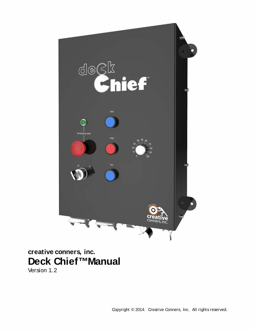
creative conners, inc.
Deck Chief™ Manual Version 1.2
Copyright © 2014. Creative Conners, Inc. All rights reserved.

Deck Chief Manual
Page 2
Deck Chief Manual
Page 3
TableofContentsGetting Started .......................................................................................................................................................... 4
What’s in the box? ................................................................................................................................................. 4
Deck Chief Features ............................................................................................................................................... 5
Installation ................................................................................................................................................................. 6
Powering Up .............................................................................................................................................................. 7
Power Input Connection ........................................................................................................................................ 7
Motor and Brake Connections ............................................................................................................................... 7
Limits Connection .................................................................................................................................................. 8
Remote Pendant .................................................................................................................................................. 10
Using the Deck Chief ................................................................................................................................................ 11
Move the Motor ................................................................................................................................................... 11
Stop the Motor .................................................................................................................................................... 12
Lock Out Unauthorized Users .............................................................................................................................. 12
Drive Fault ........................................................................................................................................................... 12
Troubleshooting ...................................................................................................................................................... 13
Technical Support ................................................................................................................................................ 13
Specifications ........................................................................................................................................................... 14
Electrical Specifications ....................................................................................................................................... 14
Physical Specifications ......................................................................................................................................... 15
Default Mitsubishi Parameters ............................................................................................................................ 15
PLC Ladder for Mitsubishi .................................................................................................................................... 16
Wiring Diagram ................................................................................................................................................... 16

Deck Chief Manual
Page 4
GettingStarted
The Deck Chief is simple motor controller designed for theatre. For applications where ease‐of‐use is
paramount, the Deck Chief provides intuitive push‐button operation with variable speed, soft‐start, limit
switch inputs, and an optional remote control pendant. For traveler curtains, roll‐down screens, display
turntables, simple slip stages, or many other motorized devices found on stage the Deck Chief is ideal. This manual will guide you through:
Unpacking
Installation
Powering up
Operation If you need help along the way contact us on our website (creativeconners.com), via email
([email protected]), or by phone (401‐289‐2942)
What’sinthebox?
Inside the box you should find:
Reference manual (this document)
Deck Chief motor controller
6‐pin power input connector
10‐pin motor & brake plug
6‐pin limit plug
12‐pin remote pendant terminator plug
If any of these items are missing, please contact us immediately for a replacement. If you purchased any power cables, limit switches, or other accessories, those items are packaged separately.

Deck Chief Manual
Page 5
DeckChiefFeatures
The Deck Chief was created to satisfy the need for simple and safe variable‐speed operation of motorized
curtains, turntables, projection screens and other effects in theatrical facilities and live event venues. It
features:
Figure 1
Figure 2
Deck Chief Manual
Page 6
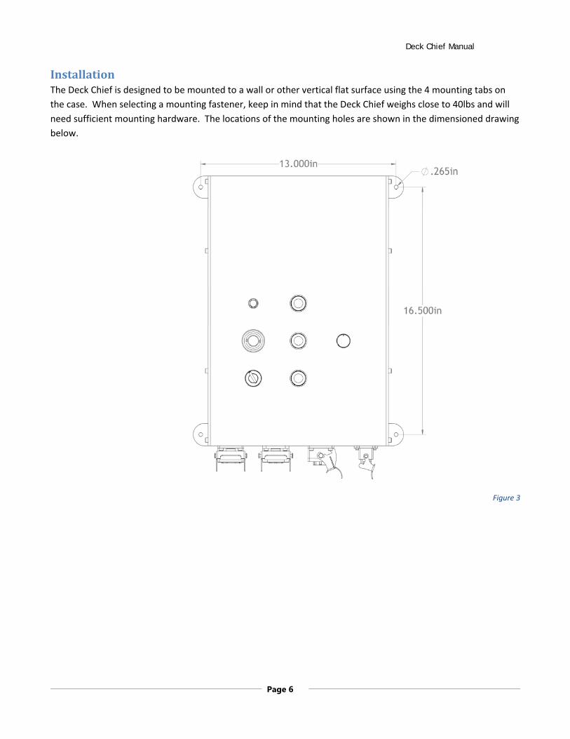
InstallationThe Deck Chief is designed to be mounted to a wall or other vertical flat surface using the 4 mounting tabs on
the case. When selecting a mounting fastener, keep in mind that the Deck Chief weighs close to 40lbs and will
need sufficient mounting hardware. The locations of the mounting holes are shown in the dimensioned drawing
below.
Figure 3

Deck Chief Manual
Page 7
PoweringUpAfter the Deck Chief is installed, it is time to power it up and get your machine spinning. The Deck Chief 5HP
requires a 30‐amp, 200VAC‐240VAC, 3‐phase, 4‐wire circuit (3 hot legs and a ground). There is no internal
branch circuit protection, so you must power the Stagehand from a branch circuit with proper over‐current
protection.
PowerInputConnectionThe power inlet on the Deck Chief is a 6‐pin rectangular plug (Automation Direct Part #ZP‐MC16B‐1‐MS006).
The pin‐out is shown below:
Figure 4
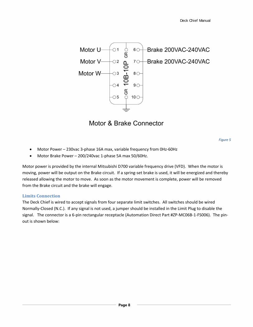
MotorandBrakeConnectionsPower output connections for a motor and spring‐set, fail‐safe brake have been combined into a single
connector. The connector is a 10‐pin rectangular receptacle (Automation Direct Part #ZP‐MC10B‐1‐FS010). The
pin‐out is shown below:
Deck Chief Manual
Page 8
Figure 5
Motor Power – 230vac 3‐phase 16A max, variable frequency from 0Hz‐60Hz
Motor Brake Power – 200/240vac 1‐phase 5A max 50/60Hz.
Motor power is provided by the internal Mitsubishi D700 variable frequency drive (VFD). When the motor is
moving, power will be output on the Brake circuit. If a spring‐set brake is used, it will be energized and thereby
released allowing the motor to move. As soon as the motor movement is complete, power will be removed
from the Brake circuit and the brake will engage.
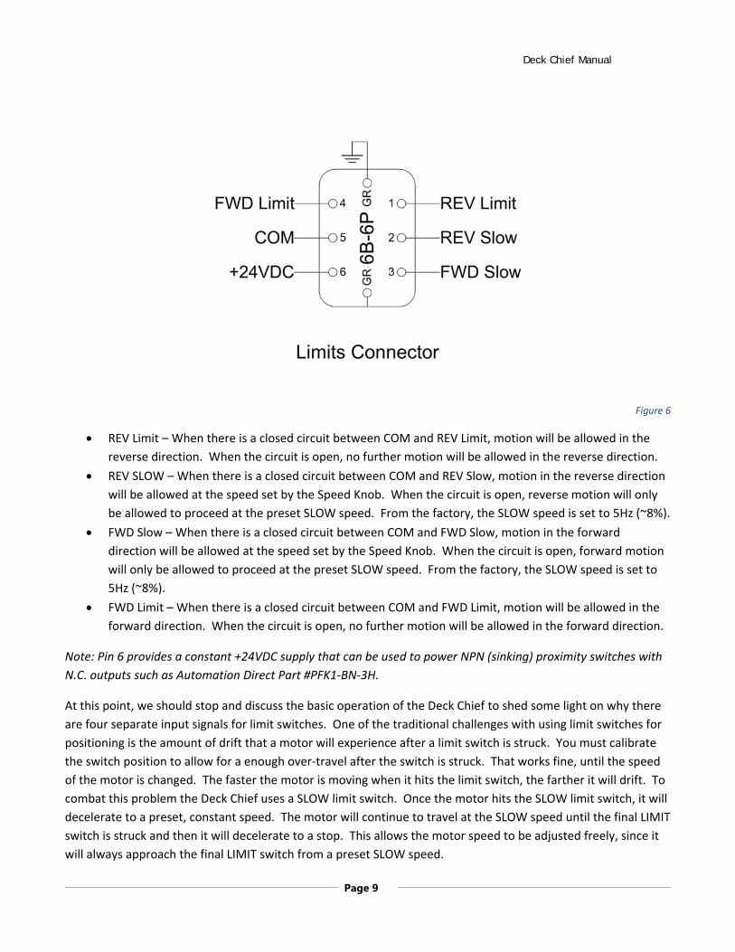
LimitsConnectionThe Deck Chief is wired to accept signals from four separate limit switches. All switches should be wired
Normally‐Closed (N.C.). If any signal is not used, a jumper should be installed in the Limit Plug to disable the
signal. The connector is a 6‐pin rectangular receptacle (Automation Direct Part #ZP‐MC06B‐1‐FS006). The pin‐
out is shown below:
Deck Chief Manual
Page 9
Figure 6
REV Limit – When there is a closed circuit between COM and REV Limit, motion will be allowed in the
reverse direction. When the circuit is open, no further motion will be allowed in the reverse direction.
REV SLOW – When there is a closed circuit between COM and REV Slow, motion in the reverse direction
will be allowed at the speed set by the Speed Knob. When the circuit is open, reverse motion will only
be allowed to proceed at the preset SLOW speed. From the factory, the SLOW speed is set to 5Hz (~8%).
FWD Slow – When there is a closed circuit between COM and FWD Slow, motion in the forward
direction will be allowed at the speed set by the Speed Knob. When the circuit is open, forward motion
will only be allowed to proceed at the preset SLOW speed. From the factory, the SLOW speed is set to
5Hz (~8%).
FWD Limit – When there is a closed circuit between COM and FWD Limit, motion will be allowed in the
forward direction. When the circuit is open, no further motion will be allowed in the forward direction.
Note: Pin 6 provides a constant +24VDC supply that can be used to power NPN (sinking) proximity switches with
N.C. outputs such as Automation Direct Part #PFK1‐BN‐3H.
At this point, we should stop and discuss the basic operation of the Deck Chief to shed some light on why there
are four separate input signals for limit switches. One of the traditional challenges with using limit switches for
positioning is the amount of drift that a motor will experience after a limit switch is struck. You must calibrate
the switch position to allow for a enough over‐travel after the switch is struck. That works fine, until the speed
of the motor is changed. The faster the motor is moving when it hits the limit switch, the farther it will drift. To
combat this problem the Deck Chief uses a SLOW limit switch. Once the motor hits the SLOW limit switch, it will
decelerate to a preset, constant speed. The motor will continue to travel at the SLOW speed until the final LIMIT
switch is struck and then it will decelerate to a stop. This allows the motor speed to be adjusted freely, since it
will always approach the final LIMIT switch from a preset SLOW speed.

Deck Chief Manual
Page 10
When setting the switch positions, you should set the position of the FWD SLOW switch so that it will be struck
before the FWD LIMIT when moving forward. It follows that you should also set the position of the REV SLOW
switch so that it is struck before the REV LIMIT when moving forward. The diagram below shows a schematic of
how the motor will move in the forward direction.
Figure 7
To describe the sequence depicted above:
The forward button is pressed and released.
The motor accelerates to the speed set on the knob in two seconds.
The motor continues forward at the knob speed until the forward slow switch is struck.
When the forward slow switch is struck, the motor decelerates to the fixed SLOW speed in two seconds.
The motor will continue to move forward at the fixed SLOW speed (not affected by the knob) until the forward limit switch is struck.
When the forward limit switch is struck, the motor decelerates to a stop in two seconds.
RemotePendantThe Deck Chief has a connector for an optional Remote Pendant. The Remote Pendant has an Emergency Stop
circuit and therefore it either must be connected, or the provided Pendant Terminator plug must be inserted to
defeat the Remote Pendant feature.

Deck Chief Manual
Page 11
UsingtheDeckChiefOnce all of your connections are made, either by plugging in a pre‐wired Creative Conners machine or by wiring
up your own machine, the next step is to power up and make something move. It is a good idea to do the initial
movements without any load attached. Once you are comfortable that everything is working properly, then you
can attach your curtain, screen, turntable, etc.
MovetheMotor
Figure 8
Moving the motor with the Deck Chief is simple.
Confirm that the key switch is turned ON.
Install either the provided Remote Terminator, or a Remote Pendant.
Set the desired speed on the knob.
Press either the FWD or REV button. The buttons are illuminated when the respective limit switch is not
struck. In other words, if the FWD button is illuminated, you can press the button and the motor will
move forward. If the FWD limit is engaged, the button will be dark and pressing the button will have not
effect.
Deck Chief Manual
Page 12
Once the motor is moving, the button that correlates to the direction of travel will quickly blink indicating that
the motor is moving at the speed selected on the knob. If the appropriate SLOW switch is struck, the button will
blink slowly indicating that the motor is moving at the preset SLOW speed.
The Deck Chief operates in a “latching” mode. Once you press a button, the Deck Chief will continue to run until
you press a stop button or the motor hits a limit switch. This is in contrast to “dead‐man” operation where the
operation button must be depressed constantly. There should be obvious safety implications to this design
choice. The Deck Chief is intended for use in applications where unattended motion will not cause harm to
people. If you are moving heavy things quickly that could collide with people, consider our Stagehand controllers
that are built for such applications.
StoptheMotorThere are two methods of stopping the motor before it reaches one of its limit switches.
Press the STOP button. The motor will decelerate to a stop within two seconds.
Press the Emergency Stop button. The motor will stop instantly and the brake will be applied instantly.
If you press the Emergency Stop button, a few things happen:
Power is removed from the motor output circuit.
Power is removed from the brake circuit, engaging the brake.
Both direction buttons will darken, indicating that no movement can take place while the emergency
stop is active.
The light above the Emergency Stop button will illuminate, showing that the emergency stop circuit is
activated.
To release the Emergency Stop button, turn it clockwise. It will spring back to a released state. If all is well, the
FWD and REV buttons will illuminate again.
The Emergency Stop circuit uses a dedicated safety module that will detect any problems with either the
Emergency Stop button, or the safety circuit that guarantees power is removed from the motor during an
emergency. If you release the Emergency Stop button and the FWD and REV buttons do not illuminate, it could
mean that an internal safety component has failed and to insure safe operation the dedicated safety module will
not allow motion. If that occurs, please give us a call to help troubleshoot or return the Deck Chief for service.
LockOutUnauthorizedUsersThe Deck Chief may be permanently installed in a facility and should be protected from accidental or malicious
operation. Beneath the Emergency Stop button a key switch is provided to lock out the operation panel. Simply
turn the key switch to OFF and remove the key for safe keeping. The key switch is a Square D part # ZB5AG2. If
you need a replacement key one can be ordered from Creative Conners or your favorite Square D distributor.
DriveFaultInternally, the Deck Chief uses a high‐quality Mitsubishi D700 VFD to power the motor. There are various
conditions that can cause the VFD (variable frequency drive) to enter a fault condition. Low voltage, over‐
current, disconnected motor are just a few examples. If the drive faults, the FWD & REV buttons will flash in an
Deck Chief Manual
Page 13
alternating pattern. To reset the drive and try to move again, press and hold both the FWD and REV buttons for
a few seconds. The Deck Chief will attempt to reset the drive and restore normal operation. If the drive
continues to fault regularly, give us a call to help troubleshoot.
TroubleshootingIf you’ve reached this section of the manual, things aren’t going well. We are very sorry, but we are always here
to help. Our various methods of communication can be found in the Technical Support section.
TechnicalSupportDespite our best efforts and intentions to provide reliable equipment and clear instructions, there may come a
time that you need more direct, personal help. We are happy to do that too. Please get in touch in whatever
way is most convenient:
Phone: 401‐289‐2942. We’re open weekdays 8:30am – 5:00pm EST. If you call outside of normal
business hours (like during tech, or pre‐show check, or intermission), one of us will be on‐call with a cell‐
phone gaff‐taped to his hand. Listen to the message on our main phone number to get the cell phone
number of the technician on‐call.
Fax: 401‐289‐0259. Honestly, I don’t think anyone uses the fax for tech support, but you are free to be
the first.
Email: [email protected]. Email can be really convenient for tech support if you don’t have
a time‐critical problem. If you are having trouble with a specific cue in a show, please email us your
show file and log file from Spikemark with a description of the issue. We respond within 24 hours, but
usually it’s just a matter of minutes.
Web forum: http://creativeconners.com/phpBB3/. Our forum has some cobwebs these days, not too
many folks prefer it over the phone or email, but we still check it religiously every day and answer any
questions that come up.
Deck Chief Manual
Page 14
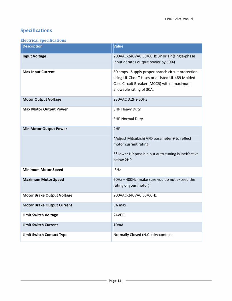
Specifications
ElectricalSpecificationsDescription Value
Input Voltage 200VAC‐240VAC 50/60Hz 3P or 1P (single‐phase
input derates output power by 50%)
Max Input Current 30 amps. Supply proper branch circuit protection
using UL Class T fuses or a Listed UL 489 Molded
Case Circuit Breaker (MCCB) with a maximum
allowable rating of 30A.
Motor Output Voltage 230VAC 0.2Hz‐60Hz
Max Motor Output Power 3HP Heavy Duty
5HP Normal Duty
Min Motor Output Power 2HP
*Adjust Mitsubishi VFD parameter 9 to reflect
motor current rating.
**Lower HP possible but auto‐tuning is ineffective
below 2HP
Minimum Motor Speed .5Hz
Maximum Motor Speed 60Hz – 400Hz (make sure you do not exceed the
rating of your motor)
Motor Brake Output Voltage 200VAC‐240VAC 50/60Hz
Motor Brake Output Current 5A max
Limit Switch Voltage 24VDC
Limit Switch Current 10mA
Limit Switch Contact Type Normally Closed (N.C.) dry contact

Deck Chief Manual
Page 15
PhysicalSpecifications
DefaultMitsubishiParametersParameter
Code Description Value Description
1 Maximum Frequency 120Hz max output frequency 6 Low speed Frequency 5Hz7 Acceleration time 2 seconds 8 Deceleration time 2 seconds 9 Motor full load amps 16
13 Starting frequency 0.5 Motor won’t start until the speed signal is at least this value.
30 Regenerative function 1 External brake resistor, L1/L2/L3 power source 70 Regenerative brake duty 10% duty cycle of the braking resistor 71 Motor type 3 Other mfg. standard motor 72 Carrier frequency 15 Reduces output noise 73 Analog input selection 1 Terminal 2 input 0 to 5V without reversing
Deck Chief Manual
Page 16
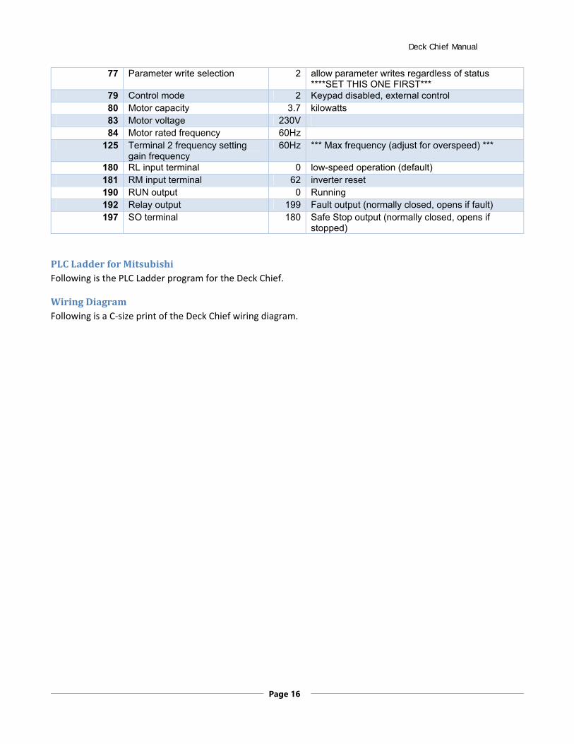
77 Parameter write selection 2 allow parameter writes regardless of status ****SET THIS ONE FIRST***
79 Control mode 2 Keypad disabled, external control 80 Motor capacity 3.7 kilowatts 83 Motor voltage 230V84 Motor rated frequency 60Hz
125 Terminal 2 frequency setting gain frequency
60Hz *** Max frequency (adjust for overspeed) ***
180 RL input terminal 0 low-speed operation (default) 181 RM input terminal 62 inverter reset 190 RUN output 0 Running 192 Relay output 199 Fault output (normally closed, opens if fault) 197 SO terminal 180 Safe Stop output (normally closed, opens if
stopped)
PLCLadderforMitsubishiFollowing is the PLC Ladder program for the Deck Chief.
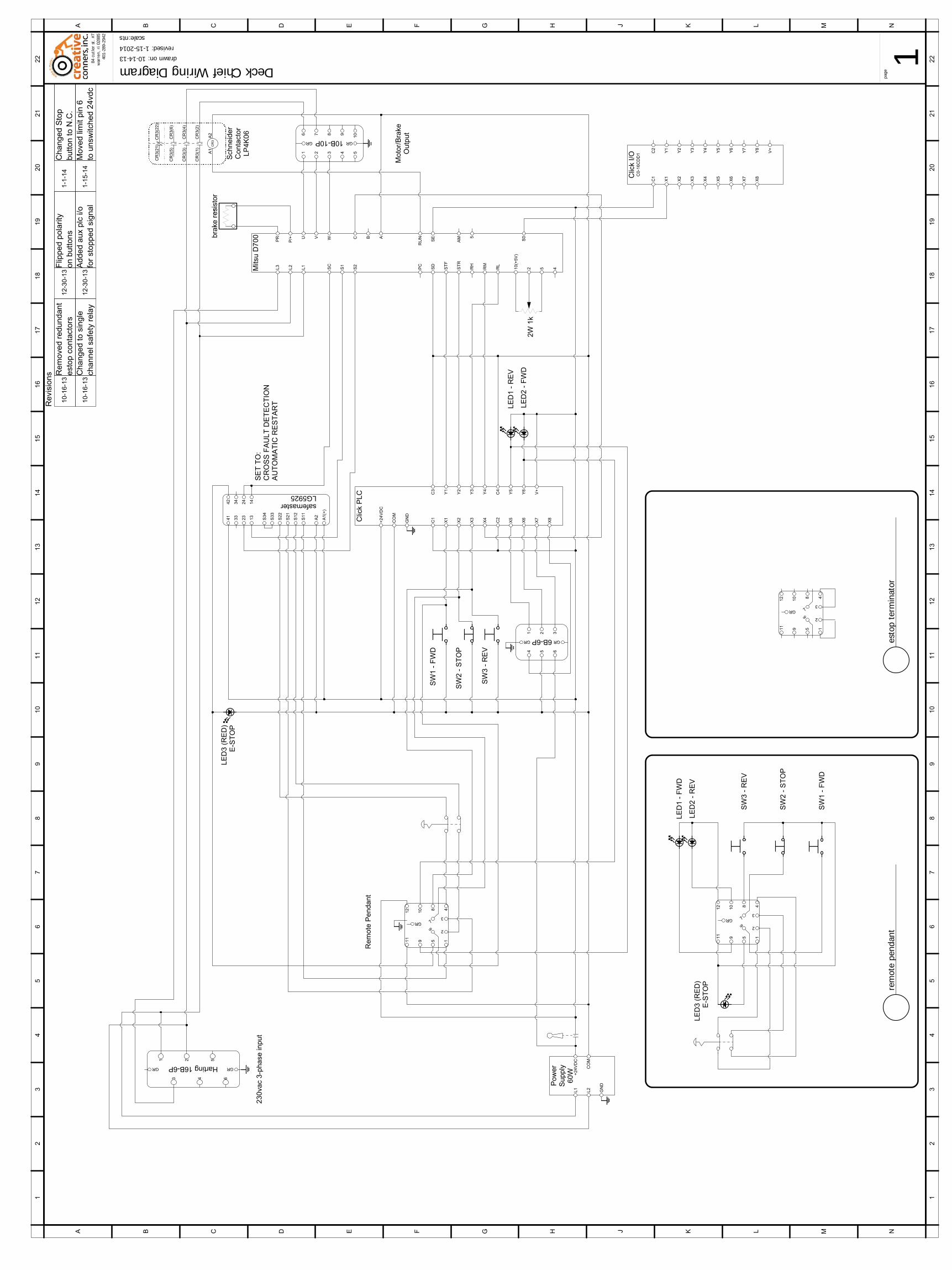
WiringDiagramFollowing is a C‐size print of the Deck Chief wiring diagram.

DeckChiefPLC
Main Program(Page 1 of 3)
Page 1 of 3 (Total Pages)

DeckChiefPLC
Main Program(Page 2 of 3)
Page 2 of 3 (Total Pages)

DeckChiefPLC
Main Program(Page 3 of 3)
Page 3 of 3 (Total Pages)
L1
L2
L3
PR
P/+ U V W
ST
F
ST
R
RH
RM
RL
SD
PC
10
(+5
V)
2 5 4S1
S2
SC
C B A
RU
N
SE
AM 5
S0
Mits
u D
700
+2
4V
DC
CO
M
GN
D
C1
X1
X2
X3
X4
C2
X5
X6
X7
X8
C3
Y1
Y2
Y3
Y4
C4
Y5
Y6
V+
Clic
k P
LC
L1
L2
GN
D
CO
M
+2
4V
DC
Po
we
rS
uppl
y6
0W
Sch
neid
er
Con
tact
orLP
4K06
CR
3
CR
3(1
)C
R3
(2)
CR
3(3
)C
R3(4
)
CR
3(5
)C
R3
(6)
CR
3(2
1)
CR
3(2
2)
A1
A2
A2
23
13
33
A1
(+)
24
14
34
41
42
S11
S12
S21
S22
S33
S34
safemasterLG5925
230va
c 3-
phas
e in
put
GRGR Harting 16B-6P
1
3
2
4 6
5
1 2 3 4 5
6 7 8 9
10
GR GR10B-10P
1 2 3
4 5 6
GR GR6B-6P
brak
e r
esis
tor
SW
1 -
FW
D
SW
2 -
ST
OP
SW
3 -
RE
V
LED
1 -
RE
V
LED
2 -
FW
D
1
2
3
4
5
67
8
10
12
911
GR
LE
D3
(RE
D)
E-S
TO
P
Moto
r/B
rake
Out
put
Rem
ote P
en
da
nt
1
2
3
4
5
67
810
12
911
GR
SW
1 -
FW
D
SW
2 -
ST
OP
SW
3 -
RE
V
LE
D3
(RE
D)
E-S
TO
P
2W 1
k
1
2
3
4
5
67
8
10
12
911
GR
LED
1 -
FW
D
LED
2 -
RE
V
C1
X1
X2
X3
X4
C2
X5
X6
X7
X8
Y1
Y2
Y3
Y4
Y5
Y6
V+
Clic
k I/
OC
0-1
6C
DD
1 Y7
Y8
SE
T T
O:
CR
OS
S F
AU
LT D
ET
EC
TIO
NA
UT
OM
AT
IC R
ES
TA
RT
84 c
utle
r st
. #7
war
ren,
ri 02
885
401-
289-
2942
page
1Deck Chief Wiring Diagramdrawn on: 10-14-13revised: 1-15-2014
scale:nts
1 1
2 2
3 3
4 4
5 5
6 6
7 7
8 8
9 9
10 10
11 11
12 12
13 13
14 14
15 15
16 16
17 17
18 18
19 19
20 20
21 21
22 22
AA
BB
CC
DD
EE
FF
GG
HH
JJ
KK
LL
MM
NN
Re
visi
on
s
10-1
6-13
Re
mo
ved
re
du
nd
an
te
sto
p c
on
tact
ors
rem
ote
pend
ant
esto
p te
rmin
ator
10-1
6-13
Ch
an
ge
d t
o s
ingle
cha
nn
el s
afe
ty r
ela
y12
-30-
13A
dd
ed a
ux
plc
i/o
for
stopped s
ignal
12-3
0-13
Flip
pe
d p
ola
rity
on
buttons
1-1-
14C
ha
ng
ed S
top
bu
tto
n t
o N
.C.
1-15
-14
Mo
ved
lim
it pin
6to
un
switc
he
d 2
4vd
c