Embed Size (px)
Citation preview

Creating and Cutting a Part on the Spadix CNC Plasma
Table Using BOBCAD-GOLD 14.1 and TurboCNC
SB Precision, LLC
Version 1
Create the Part Geometry
In this tutorial we will create a simple part out of 1/16” steel sheet that is 3x3”inches square with a 1” diameter hole exactly in the center
+ Make sure the plasma cutter is turned off, start the computer and exit Turbo CNC. at the C:\ prompt type “Bobcad” and press enter. At the main menu choose Bobcad-cam. Under START OPTIONS choose “1. – Start New Drawing”. Enter a name for the drawing when prompted (such as “test”)
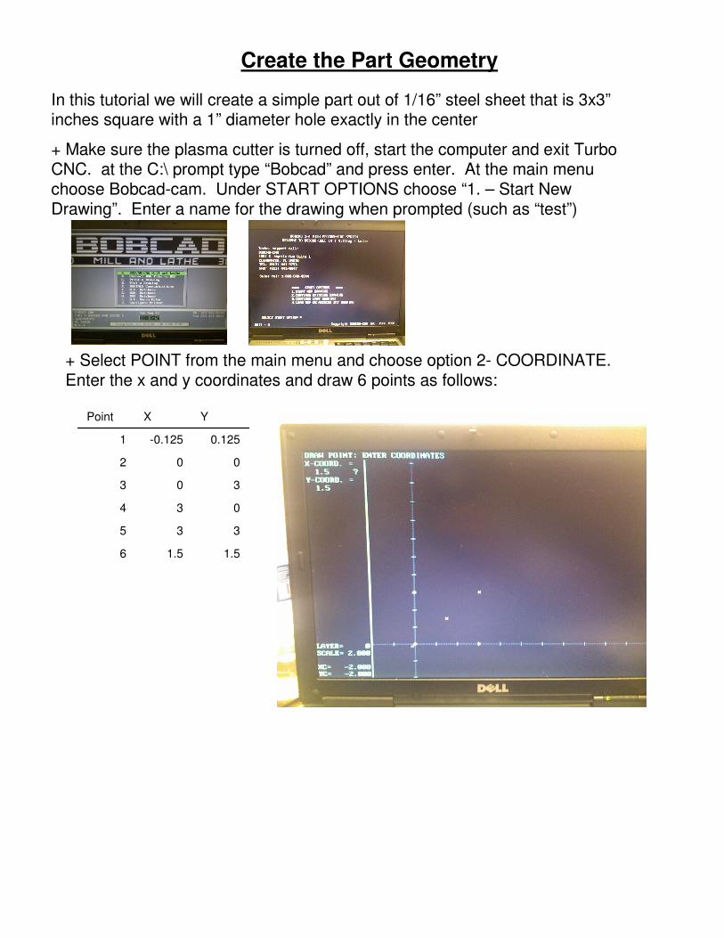
+ Select POINT from the main menu and choose option 2- COORDINATE. Enter the x and y coordinates and draw 6 points as follows:
1.51.56
335
034
303
002
0.125-0.1251
YXPoint

Create the Part Geometry+ From the main menu select LINE and choose option 3- JOIN. Use the mouse to select the lower right point and then select the upper right point. You will see a line drawn automatically. Repeat for the other 3 sides of the square. Then press the “ESC” key
+ From the main menu select ARC and choose option 2- POINT CNTR. Enter .5 for the radius and then select the point in the center of the square. You will see a circle drawn. When you are done press the “ESC” key.

Create the Offset Tool Path Geometry
The plasma cutter has a kerf that is approximately .036” wide. We need to trace the geometry of the part by ½ of this width so that the final dimension of the part cut are as close to size as possible.
+ From the main menu select OTHER CURVES and choose option 2- OFFSET. Select SINGLE and enter .018 in the distance. Select the circle in the center of the part and then move the cursor to the inside of the circle and click the mouse.
+ From the main menu select OTHER CURVES and choose option 2- OFFSET. Select CHAIN and enter .018 in the distance. Select the left side of the square that frames the part. Move the cursor to the outside of the square and click the mouse button. Press the “]” key and choose YES. You will now see the offset trace around the part.
+ From the main menu select EDIT and choose DELETE and then SINGLE. Select and delete the original corner points, circle and square.
+ From the main menu choose SAVE to save your drawing.
Create the Tool Paths Using the CAM Function
In this step we will use the NC....CAM functions to create the tool paths file for our CNC controller
+ From the main menu select NC......CAM and choose NEW FILE. Name the file and then choose PLASMA.CFG as the configuration.
+ Select option * RAPID and press enter to change to FEED mode.
+ Select POINT MOVE and move to the center point you created earlier.
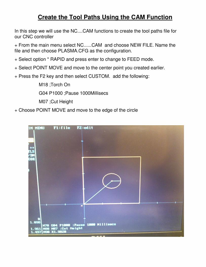
+ Press the F2 key and then select CUSTOM. add the following:
M18 ;Torch On
G04 P1000 ;Pause 1000Millisecs
M07 ;Cut Height
+ Choose POINT MOVE and move to the edge of the circle
Create the Tool Paths Using the CAM Function
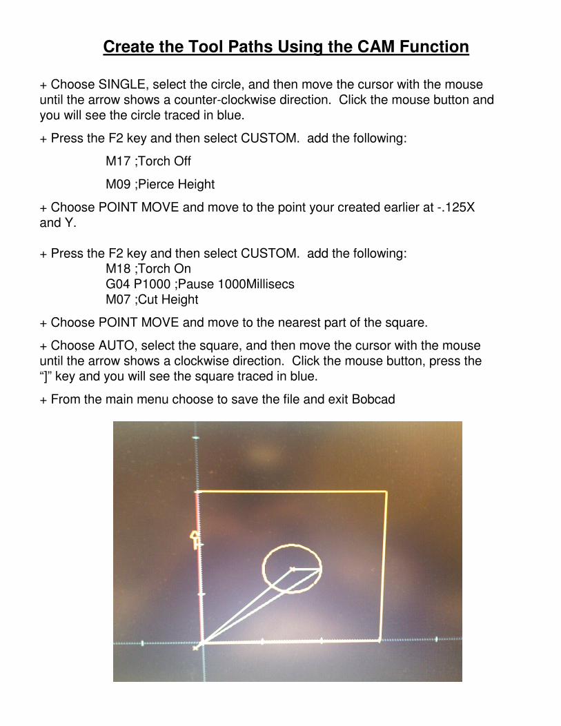
+ Choose SINGLE, select the circle, and then move the cursor with the mouse until the arrow shows a counter-clockwise direction. Click the mouse button and you will see the circle traced in blue.
+ Press the F2 key and then select CUSTOM. add the following:
M17 ;Torch Off
M09 ;Pierce Height
+ Choose POINT MOVE and move to the point your created earlier at -.125X and Y.
+ Press the F2 key and then select CUSTOM. add the following:M18 ;Torch OnG04 P1000 ;Pause 1000MillisecsM07 ;Cut Height
+ Choose POINT MOVE and move to the nearest part of the square.
+ Choose AUTO, select the square, and then move the cursor with the mouse until the arrow shows a clockwise direction. Click the mouse button, press the “]” key and you will see the square traced in blue.
+ From the main menu choose to save the file and exit Bobcad

Examining the Finished Code
Each line in the finished file is called a Block and has a specific purpose
N300 M30 ;End Program
N290 G01 X0 Y0 F100; Move to 0-0 at 100 IPM
N280 M09 ;Pierce Height
N270 M17 ;Torch Off
N260 G02 X-0.0180 Y0.0000 I0.0000 J0.0180 ;Cut the part
N250 G01 X0.0000 ;Cut the part
N240 G02 X3.0000 Y-0.0180 I-0.0180 J0.0000 ;Cut the part
N230 G01 Y0.0000 ;Cut the part
N220 G02 X3.0180 Y3.0000 I0.0000 J-0.0180 ;Cut the part
N210 G01 X3.0000 ;Cut the part
N200 G02 X0.0000 Y3.0180 I0.0180 J0.0000 ;Cut the part
N190 Y3.0000 ;Cut the part
N180 X-0.0180 Y0.0000 ;Move to the edge of the part
N170 M07 ;Cut Height
N160 G04 P1000 ;Pause 1000 Millisecs
N150 M18 ;Torch On
N140 G01 X-0.1250 Y-0.1250 ; Move to the lower edge of the part
N130 M09 ;Pierce Height
N120 M17 ;Torch Off
N110 G03 X1.9820 Y1.5000 I-0.4820 J0.0000 ; Cut the circle
N100 Z0.0000 ;Move the Z-axis to 0
N90 X1.9820 ;Move to the edge of the circle
N80 M07 ;Cut Height
N70 G04 P1000 ;Pause 1000 Millisecs
N60 M18 ;Torch On
N50 G01 X1.5000 Y1.5000; Move to the center
N40 G01 X0 Y0 F100 ;Move to 0-0 at 100 IPM
N30 M09 ;Pierce Height
N20 M17 ;Torch Off
N10 G90 ;Absolute Coordinates

Transfer the G-Code File to the Machine and Cut
Transfer the file to the machine via floppy, usb drive, or serial modem
Launch Turbocnc by turning the computer on or typing “turbocnc” at the C:\prompt
Load your program by selecting File ->Open in Editor
Press f-8 to enter the Jog menu. Use the arrow keys to move the torch to the origin of your workpiece. Next zero the axes by pressing “Z” and then “*”. Hit Esc to exit the jog menu.

Transfer the G-Code File to the Machine and Cut
It is good practice to do a dry run cut of any cnc part prior to actual machining. Raise the torch head with the control panel switch and make sure the pasmacutter is turned off. Press the f6 key to run the program and choose start.
You will see the program run through each line, and the torch gantry should move to “trace” the shape of the cut. Correct any code issues before proceeding.
Once the test cut has been made you can cut the actual part. Load the part into the machine, set the water table height to hit the back of the material part to be cut. Attach the ground clamp. Set the control panel switch to Pierce and adjust the pierce knob to set the correct height for piercing the material selected. Set the Cut knob in the middle as a starting point.
When you are confident that everything is in order turn the plasma cutter on and set the desired current. Run the program to make your part.