Embed Size (px)
Citation preview
Creating a VMware vCloud
NFV Platform R E F E R E N C E A R C H I T E C T U R E
V E R S I O N 1 . 5

R E F E R E N C E A R C H I T E C T U R E 1 . 5 / 1
Creating a VMware vCloud NFV Platform
Table of Contents
1. Introduction ................................................................................................... 4
2. Network Function Virtualization Overview ..................................................... 5 2.1 NFV Infrastructure Working Domain (NFVI)..................................................... 5 2.2 Management and Orchestration Working Domain (MANO) ............................. 6
2.2.1 Virtualized Infrastructure Manager (VIM) Functional Block .................................... 6 2.2.2 Virtual Network Function Manager Functional Block ................................................. 6 2.2.3 Network Functions Virtualization Orchestrator Functional Block ......................... 6
2.3 Operations Management Working Domain ...................................................... 6 2.4 Virtualized Network Function Working Domain (VNF) ..................................... 6 2.5 Operations Support Systems and Business Support Systems Working Domain 6
3. Architectural Overview .................................................................................. 7 3.1 Technology Mapping ....................................................................................... 7 3.2 NFVI Components Overview ........................................................................... 9
3.2.1 NFVI Components ....................................................................................................................... 9 3.2.2 MANO Components Overview ........................................................................................... 10 3.2.3 MANO Components ................................................................................................................. 11 3.2.4 Operations Management Components Overview ..................................................... 12 3.2.5 Operations Management Components .......................................................................... 13 3.2.6 VNF Components Overview ................................................................................................ 13
3.3 Conceptual Architecture ................................................................................ 14 3.3.1 Management, Edge, and Resource Clusters .............................................................. 14 3.3.2 Cluster Networking ................................................................................................................... 16 3.3.3 External Services ...................................................................................................................... 16
4. Design Overview ......................................................................................... 17 4.1 NFV Infrastructure Design ............................................................................. 17
4.1.1 VMware ESXi .............................................................................................................................. 17 4.1.2 Virtual SAN ................................................................................................................................... 17 4.1.3 NSX for vSphere ........................................................................................................................ 19
4.2 Virtualized Infrastructure Manager Design ..................................................... 21 4.2.1 VMware vCenter Server ........................................................................................................ 22 4.2.2 NSX for vSphere Manager ................................................................................................... 23 4.2.3 VMware vCloud Director ........................................................................................................ 23
4.3 NFVI Operations Management Design .......................................................... 31 4.3.1 VMware vRealize Operations Manager ......................................................................... 31 4.3.2 VMware vRealize Log Insight ............................................................................................. 33
4.4 Business Continuity and Disaster Recovery .................................................. 34 4.4.1 VMware Site Recovery Manager ...................................................................................... 34 4.4.2 VMware vSphere Replication .............................................................................................. 35 4.4.3 VMware vSphere Data Protection .................................................................................... 36
R E F E R E N C E A R C H I T E C T U R E 1 . 5 / 2
Creating a VMware vCloud NFV Platform
Figures
Figure 1: ETSI NFV Architecture Framework .................................................................................. 5
Figure 2: Technology Mapping Between VMware vCloud NFV and ETSI NFV .............................. 7
Figure 3: VMware vCloud Director Abstraction Layers .................................................................. 11
Figure 4: Conceptual Design .......................................................................................................... 14
Figure 5: Virtual SAN Storage Overview ........................................................................................ 18
Figure 6: NSX for VMware vSphere Overview ............................................................................... 20
Figure 7: VMware vCenter Server Cluster Management Components ......................................... 22
Figure 8: VMware vCloud Director Logical Design ........................................................................ 24
Figure 9: VMware vCloud Director Constructs Logical Design ...................................................... 26
Figure 10: VMware vCloud Director Allocation Pool ...................................................................... 26
Figure 11: VMware vCloud Director Reservation Pool .................................................................. 27
Figure 12: VMware vCloud Director Pay-As-You-Go Pool ............................................................ 27
Figure 13: VMware vCloud Director External Networks ................................................................ 28
Figure 14: Internal Org vDC Network ............................................................................................. 28
Figure 15: Routed Org vDC Network ............................................................................................. 28
Figure 16: Direct Org vDC Network ............................................................................................... 29
Figure 17: VMware vRealize Orchestrator Cluster Logical Design ................................................ 30
Figure 18: VMware vRealize Operations Logical Design .............................................................. 32
Figure 19: Disaster Recovery ......................................................................................................... 34
Figure 20: VMware vSphere Data Protection ................................................................................ 37
R E F E R E N C E A R C H I T E C T U R E 1 . 5 / 3
Creating a VMware vCloud NFV Platform
Tables
Table 1: Document Structure ........................................................................................................... 4
Table 2: VMware vCloud NFV Components Alignment to ETSI NFV Framework .......................... 8
Table 3: External Supporting Infrastructure Services .................................................................... 16
Table 4: NFV Infrastructure Components ...................................................................................... 17
Table 5: VIM Component Description ............................................................................................ 21
Table 6: NFVI Operations Management Components ................................................................... 31
Table 7: Management Cluster Recovery Priorities ........................................................................ 36

R E F E R E N C E A R C H I T E C T U R E V 1 . 5 / 4
Creating a VMware vCloud NFV Platform
1. Introduction
This document provides guidance in architecting a greenfield cloud solution to support Network Functions
Virtualization (NFV) based on VMware® best practice and real-world scenarios. The NFV platform
dramatically simplifies data center operations, delivering enhanced agility, rapid innovation, better
economics and scale.
The VMware vCloud® NFVTM platform supports Virtual Network Functions (VNF) workloads that run on a
VMware solution. The solution contains components that are aligned to the European Telecommunications
Standards Institute (ETSI) Network Functions Virtualisation Architectural Framework. These components
must be integrated to work well together. The components range from compute, storage and network
devices to management and monitoring services. Each of the components has numerous potentially valid
configurations, but only a few of these configurations result in an integrated, functional system that meets
business and technical requirements, and aligns with the ETSI NFVI Architectural Framework.
The following components of the ETSI NFVI Architectural Framework are addressed in this document:
• NFV Infrastructure (NFVI)
• Virtualized Infrastructure Manager (VIM)
• NFVI Operations Management
Audience
This document assists telecommunication and solution architects, as well as sales engineers, field
consultants, advanced services specialists, and customers who are responsible for telco cloud / NFV
services, in building an infrastructure to maximize the benefits of using the VMware NFV bundle of solutions.
VMware vCloud NFV Reference Architecture Versioning
While this Reference Architecture covers the second release of vCloud NFV, the numbering scheme of the
Reference Architecture has been changed to remain consistent with the new software release. For this
reason, this Reference Architecture is now referred to as version 1.5.
Document Structure
This document is divided into the sections listed in Table 1.
S E C TI O N DE S C RI P TI ON
Network Function
Virtualization This section of the document introduces the core concepts of the ETSI
NFV Architectural Framework.
Architectural
Overview This section of the document introduces the core concepts of the vCloud
NFV platform in relation to the ETSI NFV Architectural Framework.
Design Overview This section of the document describes the components required to
build the NFVI element and design guidelines.
Table 1: Document Structure

R E F E R E N C E A R C H I T E C T U R E V 1 . 5 / 5
Creating a VMware vCloud NFV Platform
2. Network Function Virtualization Overview
NFV is an architectural framework developed by the ETSI NFV Industry Specification Groups. This
framework aims to transform the telecommunication business through lower costs, rapid innovation, and
scale. The ETSI NFV Architectural Framework provides a standardized model that moves away from the
proprietary, purpose-built hardware dedicated to a single service, and toward network functions that are
delivered through software virtualization, as VNFs on commercial off-the-shelf (COTS) hardware. The result
is a network that is more agile and able to respond to the on-demand, dynamic needs of
telecommunications traffic and services. The NFV framework identifies functional blocks, and the main
reference points between such blocks. Some of these are already present in current deployments, while
others need to be added to support the virtualization process and consequent operation.
Figure 1 shows an overview of the ETSI NFV Architectural Framework, depicting the functional blocks and
reference points within the overarching NFV framework. Each functional block is shown with solid borders
and is within the scope of NFV. The architectural framework is supplemented by the NFVI Operations
Management functional block, which is not part of the standard NFV framework and is separated from the
Virtualized Infrastructure Manager (VIM) based on best practices. The NFVI Operations Management
functional block is essential in order to run a production platform. The ETSI NFV Architectural Framework
focuses on the functions and capabilities necessary in order to implement the virtualization and operation of
the network. Functional blocks above the dotted red line are not within the scope of this paper.
Figure 1: ETSI NFV Architecture Framework
2.1 NFV Infrastructure Working Domain (NFVI) The Network Functions Virtualization Infrastructure (NFVI) working domain is the foundational layer of NFV.
It provides the virtual compute, storage, and network infrastructure, as well as the physical compute,
storage, and network infrastructure on which the VNFs are deployed and executed. NFVI nodes are
deployed in multiple sites and regions to provide high-availability service, and to support locality as well as
workload latency requirements. The virtualization layer provided by the hypervisor empowers workloads to
be agnostic to the underlying hardware. This approach allows operators to choose hardware from their
preferred vendors at competitive prices and to upgrade hardware independently from workloads.

R E F E R E N C E A R C H I T E C T U R E V 1 . 5 / 6
Creating a VMware vCloud NFV Platform
2.2 Management and Orchestration Working Domain (MANO) The Management and Orchestration (MANO) working domain covers the orchestration and lifecycle
management of physical and software resources. MANO includes three elements to support the
infrastructure virtualization and lifecycle management of VNFs, and to focus on all virtualization-specific
management tasks necessary within the NFV framework.
2.2.1 Virtualized Infrastructure Manager (VIM) Functional Block
The Virtualized Infrastructure Manager (VIM) is a functional block within the MANO working domain that is
responsible for controlling, managing and monitoring the NFVI compute, storage, and network resources. It
exposes this functionality northbound to allow VNF managers and NFV orchestrators the ability to deploy
and manage VNFs. It exercises the same functionality southbound to the hypervisors and controllers in the
NFVI. The VIM manages the allocation and release of virtual resources, and the association of these to
physical resources, including optimization. The complete inventory of the NFVI is maintained in the VIM,
including the linkage between components and how they relate to an instance of a VNF workload, to allow
for monitoring in the context of a single VNF. The VIM provides the API that allows the VNF Manager to
manage the complete lifecycle of all of the VNFs.
2.2.2 Virtual Network Function Manager Functional Block
This document does not cover the Virtual Network Function Manager (VNFM) functional block. For
additional information about the VNFM functional block, read the ETSI Network Functions Virtualisation
(NFV) Architectural Framework document.
2.2.3 Network Functions Virtualization Orchestrator Functional Block
This document does not cover the NFV Orchestrator (NFVO) functional block. For additional information
about the NFV Orchestrator functional block, read the ETSI Network Functions Virtualisation (NFV)
Architectural Framework document.
2.3 Operations Management Working Domain The NFVI Operations Management components are considered part of the MANO working domain
functional block and are responsible for providing and extending the visibility of faults, configuration,
accounting, performance, and security (FCAPS) of the NFVI. These northbound reporting components
provide infrastructure alarms, events, and measureable metrics relating to both the NFVI working domain
and the VNF workloads. Implementation of the VMware vCloud NFV platform expands the capabilities of
this functional block through a unique portfolio of solutions that includes business continuity and disaster
recovery (BCDR) capabilities across the MANO working domain.
2.4 Virtualized Network Function Working Domain (VNF) This document does not cover the VNF working domain. For additional information about the VNF working
domain, read the ETSI Network Functions Virtualisation (NFV) Architectural Framework document.
2.5 Operations Support Systems and Business Support Systems Working Domain
The vCloud NFV platform exposes application programmable interfaces (APIs) that can be consumed from
one or multiple Operations Support Systems and Business Support Systems (OSS / BSS). These are not
described in this document. For information about the Operations Support Systems and Business Support
Systems (OSS / BSS) working domain, read the ETSI Network Functions Virtualisation (NFV) Architectural
Framework document.

R E F E R E N C E A R C H I T E C T U R E V 1 . 5 / 7
Creating a VMware vCloud NFV Platform
3. Architectural Overview
Cloud computing is a model that allows ubiquitous, convenient, on-demand access to a shared pool of
configurable compute, storage, and network resources. Resources can be provisioned rapidly and released
with minimal management effort.
The vCloud NFV platform delivers a complete, integrated cloud infrastructure that simplifies data center
operations while delivering high quality service level agreements (SLAs) for all VNF instances. The vCloud
NFV platform includes the entire set of infrastructure capabilities: virtualization, software-defined data center
services, policy-based provisioning, disaster recovery for management components, and operations
management.
This document focuses on the NFVI layer and each of its supporting functions. Figure 2 highlights the
mapping between the VMware vCloud NFV functional elements and the ETSI NFV reference model.
Figure 2: Technology Mapping Between VMware vCloud NFV and ETSI NFV
3.1 Technology Mapping The vCloud NFV platform is a complete solution for Communication Service Providers (CSPs) to build and
manage a VMware based telco cloud for the deployment of VNFs. The modular architecture of the platform
offers choice and flexibility for running network functions across a cloud platform. This provides a conceptual
framework to support network function requirements, organize elements into distinct components, and
define boundaries and connections. The focus of vCloud NFV is on clearly defined goals, analysis, and
design decisions that cut through the complexity of today’s technology.
The vCloud NFV bundle packages together, in a single SKU, the essential building block solutions needed
to deploy a Network Functions Virtualization Infrastructure (NFVI) and Virtual Infrastructure Management
(VIM) platform, featuring the newest releases of production-proven VMware solutions, along with advanced
capabilities for service assurance.
Table 2 lists the components of the vCloud NFV platform as well as their alignment to the ETSI NFV
framework.

R E F E R E N C E A R C H I T E C T U R E V 1 . 5 / 8
Creating a VMware vCloud NFV Platform
COM P O NE N T
INC L UD E D I N
V C LO UD N F V
BUN D LE
REQUIRED IN
VCLOUD NFV
SOLUTION
E TS I
FU NC T I ON AL
BL O CK
VMware ESXi™ Yes Required NFVI
VMware vCenter™ Server
Appliance™ No Required VIM
VMware vSphere® Replication™ Yes Recommended NFVI
VMware vSphere® Data
Protection™ Yes Recommended
NFVI
Operations
Management
VMware Virtual SAN™ Standard Yes Recommended NFVI
VMware vRealize® Operations™
Advanced Yes Required
NFVI
Operations
Management
VMware vRealize® Log
Insight™ for vCenter™ Yes Required
NFVI
Operations
Management
VMware vCloud Director® for
Service Providers Yes Required VIM
VMware NSX®
VMware NSX® for
vSphere® No Required NFVI
VMware NSX® Manager™ No Required VIM
VMware Site Recovery
Manager™ No Recommended
NFVI
Operations
Management
Table 2: VMware vCloud NFV Components Alignment to ETSI NFV Framework

R E F E R E N C E A R C H I T E C T U R E V 1 . 5 / 9
Creating a VMware vCloud NFV Platform
3.2 NFVI Components Overview The NFVI is delivered through the use of VMware vSphere, Virtual SAN, and NSX for vSphere, and provides
these functions:
• Physical Resource Abstraction. Physical resource abstraction occurs when the physical storage,
network and compute resources are abstracted by the NFV components to provide a standardized
interface and set of features to all northbound infrastructure components, such as VNFs and Element
Management Systems (EMS). The NFV components abstract the vendor specific implementation
differences of the various hardware components and ensure that certified hardware components are
used as the foundation of the platform.
• Physical Resource Pooling. Physical resource pooling occurs when the NFV components pool the
underlying hardware resources for optimum utilization, load distribution, high availability and scalability
features. This allows for fine-grained resource allocation and control of the pooled resources based on
the specific workload requirements.
3.2.1 NFVI Components
The following section is a description of the vCloud NFV components that relate to the ETSI NFVI working
domain.
Compute ESXi hosts are the fundamental compute building blocks of the vCloud NFV platform. ESXi host resources
are distributed to run management and VNF workloads and are aggregated to build clusters of highly
available pools of compute resources. Their main purpose is to host VNFs on-boarded on to the vCloud
NFV platform as Virtual Machines (VMs).
Storage Each cluster within the vCloud NFV platform is configured to use a shared storage solution.
Shared storage between hosts within a cluster is a requirement for enabiling key functionality such as:
• VMware vSphere® High Availability (HA). VMware vSphere High Availability can rapidly
restore VNF services in case of host failure.
• VMware vSphere vMotion®. VMware vSphere vMotion is used to move live, running
workloads to facilitate maintenance tasks and load balancing among hosts in a cluster, with
minimal service disruption.
The shared storage can be provided through Virtual SAN or a certified third party shared storage solution.
Virtual SAN provides shared storage by aggregating the local disks and flash drives with which each host is
equipped. Third party storage solutions with storage replication adapters that meet VMware storage
compatibility guidelines are also supported. For the purpose of this vCloud NFV 1.5 Reference Architecture,
only the Virtual SAN based storage solution will be discussed.
As new network functions are on-boarded, virtual machine requirements such as capacity or performance to
support the VNF may dictate the need for additional storage options.
Network NSX for vSphere creates virtual networks that include all of the necessary network functionality a VNF might
require from the NFVI.
The NSX network infrastructure is responsible for providing the network virtualization component of the

R E F E R E N C E A R C H I T E C T U R E V 1 . 5 / 1 0
Creating a VMware vCloud NFV Platform
NFVI, and is built using these components:
• VMware NSX® Controller™. The NSX Control Plane is responsible for the creation of the logical
topology state necessary for connectivity between the VMs that form a VNF. Consisting of three
active virtual controller nodes, the VMware NSX® Controller™ cluster maintains availability in the
event of a communication disruption between nodes, or the failure of a single node. Shared fatal
failure of the controller cluster is avoided by using anti-affinity rules to ensure that no two members
of the cluster share the same physical host.
Note: The NSX controllers are implemented out-of-band and do not participate in the forwarding of
any data traffic.
• VMware NSX® Virtual Switch™. The VMware NSX® Virtual Switch™ is a distributed data plane
component within the ESXi hypervisor kernel that is used for the creation of logical overlay
networks, facilitating flexible workload placement of the VNF components. Extending the L2
functionality found natively in the VMware vSphere® Distributed Switch™, the NSX Virtual Switch
allows for arbitrary topologies to be created using VXLAN-backed logical switches, thereby
reproducing both the external connectivity and internal backplane communications a VNF can
require, for example for inter-process and VM communication. Features such as port mirroring and
Quality of Service (QoS) marking are also supported by NSX. Note: These may require configuring
the extensions within the VIM.
The NSX Virtual Switch is a multi-layer switch by default and therefore supports L3 functionality to
provide optimal routing between subnets directly within the host, for communication within the
datacenter.
Stateful firewall services are supported by the NSX Virtual Switch through the Distributed Firewall
service, also known as micro-segmentation. This functionality provides firewall policy enforcement
within the hypervisor kernel at the granularity of a per vNIC level on guest VMs, thereby supporting
fine-grained isolation and the segmentation of workloads. For example, micro-segmentation can be
used to secure the communication between management components such as vCloud Director
and vCenter, or VNF Manager and vCloud Director. Micro-segmentation can also be used to
completely isolate and block all traffic between the VNF components.
• VMware NSX® Edge™. The VMware NSX® Edge™ acts as the centralized virtual appliance for
routing traffic in and out of the virtual domain, toward other virtual or physical infrastructure. This is
also referred to as North-South communication. In addition to the routing of VNF traffic, the NSX
Edge may also provide additional L4-7 services such as stateful firewall functionality, load-
balancing, or DHCP.
When stateful services such as firewall, load-balancing, VPN and NAT are required, an active /
standby NSX Edge pair should be deployed. When NSX Edge is used solely to provide the routing
function, an ECMP configuration can be deployed to provide additional resilience and fault
tolerance.
3.2.2 MANO Components Overview
The Virtualized Infrastructure Manager (VIM) functional block is responsible for resource management
across the NFVI and is delivered through the use of vCenter Server, vCloud Director, and NSX Manager.
The VIM performs these tasks:
• NFVI Inventory Management. The management components of VIM ensure that information about the
underlying NFVI storage, network and compute resources are up-to-date and accurate. This includes
information about their configuration parameters, runtime states, and hierarchy in the inventory.
Additionally, the management components may provide different consolidated views of the inventory,
for example, information pertaining to a VNF instance across compute, storage, and networking
components.
R E F E R E N C E A R C H I T E C T U R E V 1 . 5 / 1 1
Creating a VMware vCloud NFV Platform
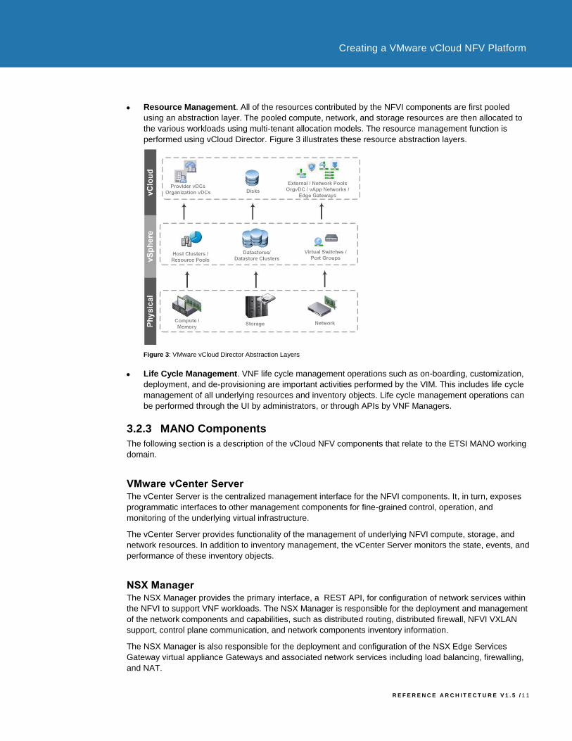
• Resource Management. All of the resources contributed by the NFVI components are first pooled
using an abstraction layer. The pooled compute, network, and storage resources are then allocated to
the various workloads using multi-tenant allocation models. The resource management function is
performed using vCloud Director. Figure 3 illustrates these resource abstraction layers.
Figure 3: VMware vCloud Director Abstraction Layers
• Life Cycle Management. VNF life cycle management operations such as on-boarding, customization,
deployment, and de-provisioning are important activities performed by the VIM. This includes life cycle
management of all underlying resources and inventory objects. Life cycle management operations can
be performed through the UI by administrators, or through APIs by VNF Managers.
3.2.3 MANO Components
The following section is a description of the vCloud NFV components that relate to the ETSI MANO working
domain.
VMware vCenter Server The vCenter Server is the centralized management interface for the NFVI components. It, in turn, exposes
programmatic interfaces to other management components for fine-grained control, operation, and
monitoring of the underlying virtual infrastructure.
The vCenter Server provides functionality of the management of underlying NFVI compute, storage, and
network resources. In addition to inventory management, the vCenter Server monitors the state, events, and
performance of these inventory objects.
NSX Manager The NSX Manager provides the primary interface, a REST API, for configuration of network services within
the NFVI to support VNF workloads. The NSX Manager is responsible for the deployment and management
of the network components and capabilities, such as distributed routing, distributed firewall, NFVI VXLAN
support, control plane communication, and network components inventory information.
The NSX Manager is also responsible for the deployment and configuration of the NSX Edge Services
Gateway virtual appliance Gateways and associated network services including load balancing, firewalling,
and NAT.
R E F E R E N C E A R C H I T E C T U R E V 1 . 5 / 1 2
Creating a VMware vCloud NFV Platform
VMware vCloud Director The vCloud Director is an abstraction layer that sits on top of the virtualized infrastructure of vCenter Server
and the NSX Manager. This enables multiple NFVI tenants to consume shared compute, storage, and
network resources in a secure multi-tenant environment. Secure multi-tenancy implies the ability to isolate
administration boundaries of NFVI tenants. VNF workload resource consumption is also isolated, even
though VNF workloads might reside on the same physical hardware.
The vCloud Director implements the open and publicly available vCloud API, which provides compatibility,
interoperability, and programmatic extensibility to Network Equipment Providers (NEP) and their VNF
Manager. The vCloud Director capabilities can be extended to create adaptors to external systems including
OSS / BSS integration.
3.2.4 Operations Management Components Overview
The underlying virtual infrastructure, including compute, storage, and network resources, relies on a holistic
management solution to collect data regarding health, capacity, and performance. This management system
is implemented using VMware vRealize® Operations™ Advanced®, VMware vRealize® Log InsightTM for
vCenterTM, VMware Site Recovery ManagerTM, vSphere Replication and VMware vSphere® Data
ProtectionTM.
Operations Management tasks include:
• NFVI Visibility. An integral part of the vCloud NFV platform includes customized dashboards created
using widgets, views, badges, and filters to focus on the information of interest. With vCloud NFV, NFVI
visibility is achieved by collecting key performance and capacity metrics from the NFVI components. An
extensible and flexible data collection mechanism means that virtually any metric can be collected from
any data source or inventory object for cause analysis. When problems occur within the NFVI,
uncovering the root cause and determining the location of the underlying platform component where the
problem lies is crucial.
• Fault Reporting. The NFVI storage, network, and compute components generate various log
messages and alarms. Each of these is correlated between the various components to troubleshoot an
issue. Operations Management components are then required to perform the necessary analysis, such
as identifying related events across component logs pertaining to a particular failure incident, in order to
aid in the troubleshooting process.
• Performance Management and Capacity Planning. On-going management of performance and
capacity across the NFVI is required for optimal performance of the VNF instances on a shared
platform. This helps to prepare for new VNFs to be on-boarded to the platform. Scheduled reports,
dashboards, and customized views are part of the implementation of Operations Management.
• Platform Resiliency. The vCloud NFV platform supports business continuity and disaster recovery of
the key management workloads residing in the management cluster. This includes high availability and
data protection of the management workloads.

R E F E R E N C E A R C H I T E C T U R E V 1 . 5 / 1 3
Creating a VMware vCloud NFV Platform
3.2.5 Operations Management Components
This section describes the vCloud NFV components that make up the operations management functional
block.
VMware vRealize Operations Manager The vRealize Operations Manager provides the capabilities necessary to achieve an integrated approach to
performance, health, and capacity analytics across the NFVI. These can either be consumed by OSS / BSS
or integrated with MANO.
The vRealize Operations Manager can be extended to gather information through management packs. The
information collected can then be filtered for relevant information, analyzed, and presented in the form of
customizable dashboards. This monitoring solution can expose an API to be used through an external
system for retrieving performance and health data pertaining to the NFVI, as well as the virtual resources
that make up the VNF instance.
The vRealize Operations Manager does not cover VNF service availability or VNF internal KPIs,
performance, and events. This information must be derived with the VNF Manager and is not included as
part of this document.
VMware vRealize Log Insight VMware vRealize Log Insight provides central, real-time analytics of syslog messages for hypervisors,
hardware, and other components of NFVI. These can be consumed by OSS / BSS, or can be integrated with
MANO.
VMware vRealize Log Insight can serve as a source of data for vRealize Operations Manager. This allows
you to perform analytics on the data from the log files of the various components.
Site Recovery Manager The Site Recovery Manager works in conjunction with various storage replication solutions, including
vSphere Replication to automate the process of migrating, recovering, testing, re-protecting, and failing back
virtual machine workloads for disaster recovery.
VMware vSphere Replication VMware vSphere Replication is a virtual machine data protection and disaster recovery solution. It is fully
integrated with vCenter Server and VMware vSphere® Web Client, providing host-based, asynchronous
replication of virtual machines, including VM storage.
VMware vSphere Data Protection VMware vSphere Data Protection is a backup and recovery solution. It is fully integrated with vCenter Server
and vSphere Web Client, providing disk-based backup of virtual machines and applications. Third party
backup solutions that are certified for vSphere may also be used.
3.2.6 VNF Components Overview
While VNF components are not covered in this document, the vCloud NFV platform provides supporting
virtual infrastructure resources such as network, compute, and storage components for the successful
deployment and operation of VNFs. VMware vCloud NFV also maintains an extensive list of VNFs that have
been verified to interoperate well with the platform. This list is located on the VMware Solution Exchange.

R E F E R E N C E A R C H I T E C T U R E V 1 . 5 / 1 4
Creating a VMware vCloud NFV Platform
3.3 Conceptual Architecture The vCloud NFV platform offers scalable architecture for multi-site deployments across different regions,
wherever VNF instances can be hosted.
The architecture is designed based on the following principles:
• VNF instances are located in specific sites within a region to cover a geographical area.
• VNF instance deployments conform to diversity rules and high availability demands.
• Multiple markets are supported to comply with legal and regulatory requirements.
Figure 4 illustrates the conceptual design of the vCloud NFV platform.
Figure 4: Conceptual Design
3.3.1 Management, Edge, and Resource Clusters
Clusters are the top level vCloud NFV logical building blocks used to segregate resources allocated to
management functions from resources dedicated to virtualized network functions. The vCloud NFV platform
consists of three cluster types used to perform specific functions. This design ensures that management
boundaries are clearly defined, capacity is plannable, and resources are allocated based on specific
workload needs.
R E F E R E N C E A R C H I T E C T U R E V 1 . 5 / 1 5
Creating a VMware vCloud NFV Platform
The cluster-specific functions are:
• Management Cluster. The management cluster contains components of the MANO working domain. It
includes the servers that make up the VIM components, as well as the NFVI Operations Management
components. This cluster contains an additional subset of the VIM components used to manage the
resources of the management cluster and to provide networking services to the management
components within the cluster.
• Edge Cluster and Resource Cluster. Edge clusters and resource clusters form the NFVI working
domain. They aggregate the underlying storage, network, and physical resources for the NFVI to
consume.
The resource clusters host the VNF workloads. These can be deployed at a multitude of sites, based on
region. The resource clusters are responsible for providing the compute resources for VNFs. Resources
made available to the VNFs can be scaled by either adding additional ESXi hosts to the resource
cluster, or by creating additional resource clusters.
The edge clusters host the network components of the NFVI, such as the network control plane, the
distributed router, and the Edge Gateway. The edge cluster along with the resource clusters are used to
facilitate software defined networking functionality, with services such as physical network bridging,
routing, firewalling, load balancing, and virtual private networking (VPN). A single edge cluster is
required at each site where a resource cluster exists, but multiple resource clusters, each pertaining to
the same or multiple VNF instances, can leverage the same edge cluster within the site.
The vCloud NFV architecture uses VMware vSphere® Distributed Resource Scheduler™ (DRS) to
continuously monitor the resource utilization of the hosts and workloads within a cluster, and to dynamically
and automatically redistribute resources to ensure that the cluster is well balanced. DRS works in
conjunction with vSphere vMotion to move live, running workloads across hosts in a cluster, with minimal
service disruption.
The automation level of a DRS enabled cluster can be set to fully automated or partially automated. When
fully automated, the DRS continuously monitors the cluster, and migrates running workloads amongst hosts
in a cluster as necessary to balance the load. When partially automated, the DRS generates migration
recommendations, but does not automatically migrate workloads in the cluster. An administrator or
orchestrator can manually approve the migration of running workloads after evaluating the DRS
recommendations.
Use DRS in the fully automated mode for the management cluster. The edge and resource clusters should
use partial DRS automation to avoid automatic run time migrations, since certain classes of VNFs can have
strict performance and network characteristics requirements. This setting can be changed after assessing
any potential impact to the VNF workloads.
VMware vSphere vMotion offers a significant advantage for maintenance and disaster recovery scenarios
for all workloads. When a host needs to be brought offline for maintenance, the vMotion feature allows
administrators to move running workloads to other hosts in the cluster, ensuring service continuity. Once the
host is back online, workloads can be migrated back to the host. An administrator can trigger the movement
of live, running workloads, irrespective of the cluster automation level, for DRS and maintenance activities.
Shared storage requirements are fulfilled at the cluster level via Virtual SAN, which pools the local storage
contributed by member hosts in the cluster. Since data is distributed across multiple hosts in the cluster, it is
protected against host failure. The vCloud NFV platform also supports certified third party shared storage
solutions.
R E F E R E N C E A R C H I T E C T U R E V 1 . 5 / 1 6
Creating a VMware vCloud NFV Platform
3.3.2 Cluster Networking
Networking functionality within the NFVI may be categorized into the following groups:
• Infrastructure Networks. Infrastructure networks are used by the hypervisor host itself for connecting
the native TCP / IP stack to the physical network. Examples of infrastructure networks include
hypervisor management traffic, vMotion traffic, and storage traffic. Note: encapsulated VXLAN traffic is
also defined as infrastructure traffic.
• Tenant Networks. Tenant networks are the logical overlay networks, or VLANs, that are connected to
the vNIC of the guest VMs running in the hypervisor. Examples of tenant networks include the VM
management network for traffic between all MANO components in the management cluster and the
VNF Networks for East-West VNF traffic.
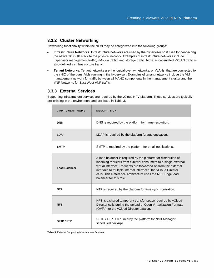
3.3.3 External Services
Supporting infrastructure services are required by the vCloud NFV platform. These services are typically
pre-existing in the environment and are listed in Table 3.
COM P O NE N T N AM E DE S C RI P TI ON
DNS DNS is required by the platform for name resolution.
LDAP LDAP is required by the platform for authentication.
SMTP SMTP is required by the platform for email notifications.
Load Balancer
A load balancer is required by the platform for distribution of
incoming requests from external consumers to a single external
virtual interface. Requests are forwarded on from the external
interface to multiple internal interfaces, the vCloud Director
cells. This Reference Architecture uses the NSX Edge load
balancer for this role.
NTP NTP is required by the platform for time synchronization.
NFS
NFS is a shared temporary transfer space required by vCloud
Director cells during the upload of Open Virtualization Formats
(OVFs) for the vCloud Director catalog.
SFTP / FTP SFTP / FTP is required by the platform for NSX Manager
scheduled backups.
Table 3: External Supporting Infrastructure Services
R E F E R E N C E A R C H I T E C T U R E V 1 . 5 / 1 7
Creating a VMware vCloud NFV Platform
4. Design Overview
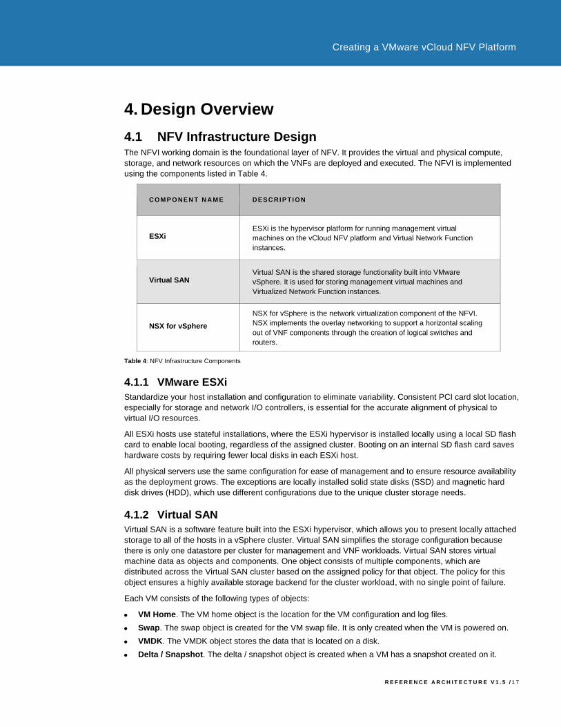
4.1 NFV Infrastructure Design The NFVI working domain is the foundational layer of NFV. It provides the virtual and physical compute,
storage, and network resources on which the VNFs are deployed and executed. The NFVI is implemented
using the components listed in Table 4.
COM P O NE N T N AM E DE S C RI P TI ON
ESXi ESXi is the hypervisor platform for running management virtual
machines on the vCloud NFV platform and Virtual Network Function
instances.
Virtual SAN Virtual SAN is the shared storage functionality built into VMware
vSphere. It is used for storing management virtual machines and
Virtualized Network Function instances.
NSX for vSphere
NSX for vSphere is the network virtualization component of the NFVI.
NSX implements the overlay networking to support a horizontal scaling
out of VNF components through the creation of logical switches and
routers.
Table 4: NFV Infrastructure Components
4.1.1 VMware ESXi
Standardize your host installation and configuration to eliminate variability. Consistent PCI card slot location,
especially for storage and network I/O controllers, is essential for the accurate alignment of physical to
virtual I/O resources.
All ESXi hosts use stateful installations, where the ESXi hypervisor is installed locally using a local SD flash
card to enable local booting, regardless of the assigned cluster. Booting on an internal SD flash card saves
hardware costs by requiring fewer local disks in each ESXi host.
All physical servers use the same configuration for ease of management and to ensure resource availability
as the deployment grows. The exceptions are locally installed solid state disks (SSD) and magnetic hard
disk drives (HDD), which use different configurations due to the unique cluster storage needs.
4.1.2 Virtual SAN
Virtual SAN is a software feature built into the ESXi hypervisor, which allows you to present locally attached
storage to all of the hosts in a vSphere cluster. Virtual SAN simplifies the storage configuration because
there is only one datastore per cluster for management and VNF workloads. Virtual SAN stores virtual
machine data as objects and components. One object consists of multiple components, which are
distributed across the Virtual SAN cluster based on the assigned policy for that object. The policy for this
object ensures a highly available storage backend for the cluster workload, with no single point of failure.
Each VM consists of the following types of objects:
• VM Home. The VM home object is the location for the VM configuration and log files.
• Swap. The swap object is created for the VM swap file. It is only created when the VM is powered on.
• VMDK. The VMDK object stores the data that is located on a disk.
• Delta / Snapshot. The delta / snapshot object is created when a VM has a snapshot created on it.
R E F E R E N C E A R C H I T E C T U R E V 1 . 5 / 1 8
Creating a VMware vCloud NFV Platform
The size of the Virtual SAN datastore depends on the number of hosts, and the number of disk drives per
host. The storage policies also affect the usable capacity of the datastore. Use sparse swap files for your
virtual machines for optimal usage of the available capacity.
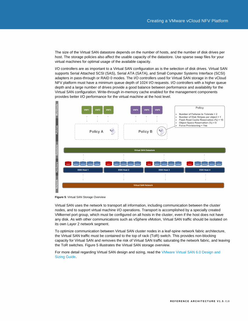
I/O controllers are as important to a Virtual SAN configuration as is the selection of disk drives. Virtual SAN
supports Serial Attached SCSI (SAS), Serial ATA (SATA), and Small Computer Systems Interface (SCSI)
adapters in pass-through or RAID 0 modes. The I/O controllers used for Virtual SAN storage in the vCloud
NFV platform must have a minimum queue depth of 1024 I/O requests. I/O controllers with a higher queue
depth and a large number of drives provide a good balance between performance and availability for the
Virtual SAN configuration. Write-through in-memory cache enabled for the management components
provides better I/O performance for the virtual machine at the host level.
Figure 5: Virtual SAN Storage Overview
Virtual SAN uses the network to transport all information, including communication between the cluster
nodes, and to support virtual machine I/O operations. Transport is accomplished by a specially created
VMkernel port group, which must be configured on all hosts in the cluster, even if the host does not have
any disk. As with other communications such as vSphere vMotion, Virtual SAN traffic should be isolated on
its own Layer 2 network segment.
To optimize communication between Virtual SAN cluster nodes in a leaf-spine network fabric architecture,
the Virtual SAN traffic must be contained to the top of rack (ToR) switch. This provides non-blocking
capacity for Virtual SAN and removes the risk of Virtual SAN traffic saturating the network fabric, and leaving
the ToR switches. Figure 5 illustrates the Virtual SAN storage overview.
For more detail regarding Virtual SAN design and sizing, read the VMware Virtual SAN 6.0 Design and
Sizing Guide.

R E F E R E N C E A R C H I T E C T U R E V 1 . 5 / 1 9
Creating a VMware vCloud NFV Platform
4.1.3 NSX for vSphere
NSX for vSphere provides logical networking services including switching, routing, and a distributed firewall
when necessary to support the desired topology of a VNF. For a given VNF, workload traffic is forwarded
over interfaces mapped to VXLAN. Use of VXLAN backed networking allows for flexible workload placement
in any resource cluster, and still provides direct L2 connectivity between VNFs without dependency on Layer
2 connectivity within the physical network.
Base your physical network on a Layer 3 leaf-spine topology. Port load balancing can be used to increase
high-availability, or to increase port-speed capacity using a technique such as Multi-Chassis Link
Aggregation Group (MC-LAG) configured on top-of-rack or end-of-row switches. This approach allows for
load balancing and fault tolerance of physical interfaces in both the edge and resource clusters. You can
also use other means to bundle physical interfaces, including using local hashing algorithms.
As part of the process to define a logical switch, a replication mode for broadcast, unknown unicast, and
multicast (BUM) traffic needs to be selected.
NSX supports three logical switch control plane modes:
• Multicast. With multicast switch control plane mode, BUM traffic is sent to a pre-defined multicast
group. Each VTEP participating in the logical switch must subscribe to the group in order to receive
multi-destination traffic for this L2 broadcast domain. This mode is typically used for integration with
legacy environments.
• Unicast. With unicast switch control plane mode, all BUM traffic is replicated on the source hypervisor
to each VTEP participating in the logical switch. This provides the simplest setup because no multicast
functionality is required in the physical network. This mode is recommended for small scale
deployments.
• Hybrid. Hybrid switch control plane mode is the recommend control mode for NFV deployments. For
VTEPs participating in the logical switch within the same L2 broadcast domain of the physical network,
multicast replication is used. Because this is within the L2 broadcast domain, the only functionality
required is IGMP snooping and IGMP querier functionality on the switches directly connected to the
hypervisor hosts.
Replication to VTEPs on other remote L3 subnets is accomplished by sending a single unicast copy to one
VTEP per remote L3 subnet. This VTEP will then subsequently provide multicast replication to other VTEPS
within the same broadcast domain. This mode is recommended as it uses the native fan-out functionality
within the physical network, while removing the complexity of having to implement Protocol Independent
Multicast (PIM) for L3 multicast routing.
R E F E R E N C E A R C H I T E C T U R E V 1 . 5 / 2 0
Creating a VMware vCloud NFV Platform
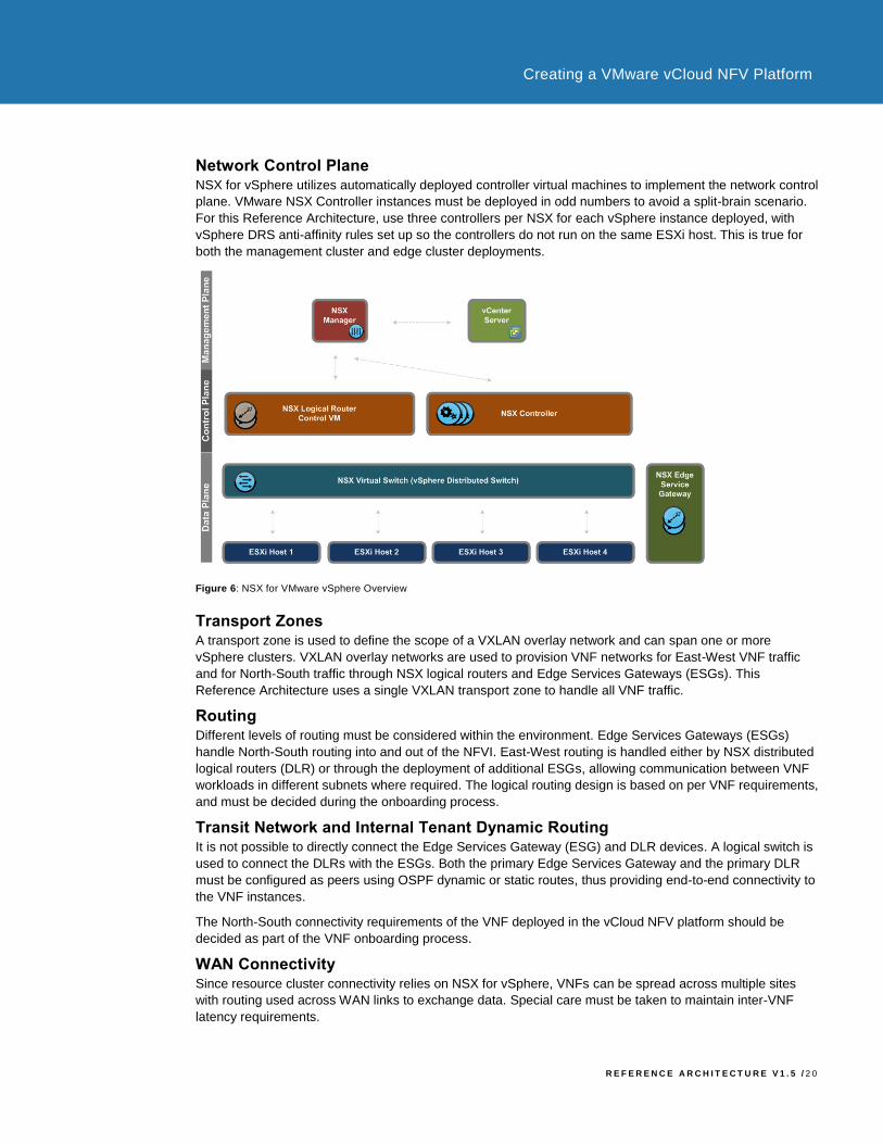
Network Control Plane NSX for vSphere utilizes automatically deployed controller virtual machines to implement the network control
plane. VMware NSX Controller instances must be deployed in odd numbers to avoid a split-brain scenario.
For this Reference Architecture, use three controllers per NSX for each vSphere instance deployed, with
vSphere DRS anti-affinity rules set up so the controllers do not run on the same ESXi host. This is true for
both the management cluster and edge cluster deployments.
Figure 6: NSX for VMware vSphere Overview
Transport Zones A transport zone is used to define the scope of a VXLAN overlay network and can span one or more
vSphere clusters. VXLAN overlay networks are used to provision VNF networks for East-West VNF traffic
and for North-South traffic through NSX logical routers and Edge Services Gateways (ESGs). This
Reference Architecture uses a single VXLAN transport zone to handle all VNF traffic.
Routing Different levels of routing must be considered within the environment. Edge Services Gateways (ESGs)
handle North-South routing into and out of the NFVI. East-West routing is handled either by NSX distributed
logical routers (DLR) or through the deployment of additional ESGs, allowing communication between VNF
workloads in different subnets where required. The logical routing design is based on per VNF requirements,
and must be decided during the onboarding process.
Transit Network and Internal Tenant Dynamic Routing It is not possible to directly connect the Edge Services Gateway (ESG) and DLR devices. A logical switch is
used to connect the DLRs with the ESGs. Both the primary Edge Services Gateway and the primary DLR
must be configured as peers using OSPF dynamic or static routes, thus providing end-to-end connectivity to
the VNF instances.
The North-South connectivity requirements of the VNF deployed in the vCloud NFV platform should be
decided as part of the VNF onboarding process.
WAN Connectivity Since resource cluster connectivity relies on NSX for vSphere, VNFs can be spread across multiple sites
with routing used across WAN links to exchange data. Special care must be taken to maintain inter-VNF
latency requirements.
R E F E R E N C E A R C H I T E C T U R E V 1 . 5 / 2 1
Creating a VMware vCloud NFV Platform
For a full description of the design considerations relevant to a NSX deployment, read the Reference
Design: VMware NSX for vSphere (NSX) Network Virtualization Design Guide in conjunction with this
document.
4.2 Virtualized Infrastructure Manager Design The VIM functional block in the MANO working domain is responsible for controlling and managing the NFVI
compute, storage, and network resources in the vCloud NFV deployment. It is also responsible for exposing
a northbound interface to support management of virtualized resources by the VNF Managers and the NFV
Orchestrator.
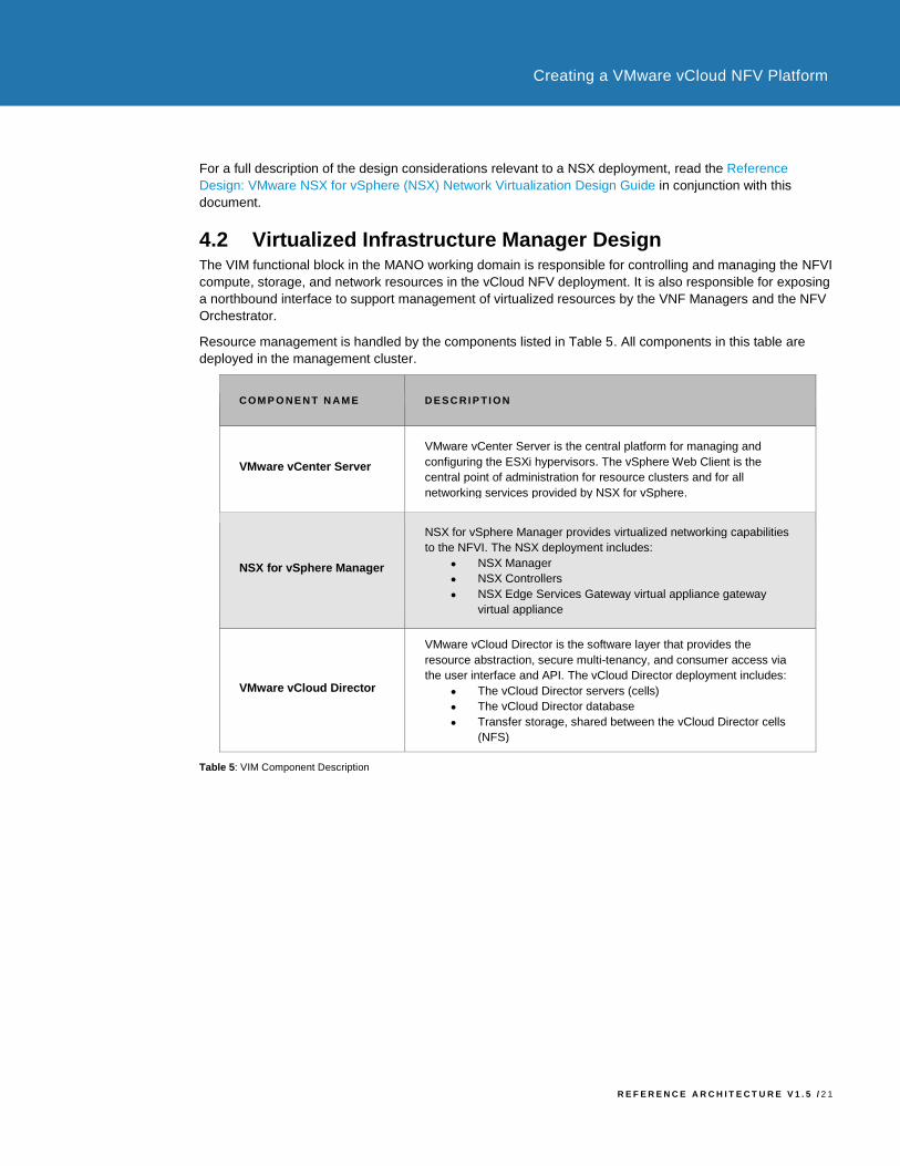
Resource management is handled by the components listed in Table 5. All components in this table are
deployed in the management cluster.
COM P O NE N T N AM E DE S C RI P TI ON
VMware vCenter Server
VMware vCenter Server is the central platform for managing and
configuring the ESXi hypervisors. The vSphere Web Client is the
central point of administration for resource clusters and for all
networking services provided by NSX for vSphere.
NSX for vSphere Manager
NSX for vSphere Manager provides virtualized networking capabilities
to the NFVI. The NSX deployment includes:
• NSX Manager
• NSX Controllers
• NSX Edge Services Gateway virtual appliance gateway
virtual appliance
VMware vCloud Director
VMware vCloud Director is the software layer that provides the
resource abstraction, secure multi-tenancy, and consumer access via
the user interface and API. The vCloud Director deployment includes:
• The vCloud Director servers (cells)
• The vCloud Director database
• Transfer storage, shared between the vCloud Director cells
(NFS)
Table 5: VIM Component Description

R E F E R E N C E A R C H I T E C T U R E V 1 . 5 / 2 2
Creating a VMware vCloud NFV Platform
4.2.1 VMware vCenter Server
The vCloud NFV platform utilizes two vCenter Server instances per site, one to manage the management
cluster itself in which all of the MANO components are deployed, and the other to manage the NFVI where
VNF workloads and their networking components are deployed. This is shown in Figure 7.
Figure 7: VMware vCenter Server Cluster Management Components
Both of the vCenter Server instances in Figure 7 are virtual appliances with an embedded database and
external Platform Services Controller (PSC). The vCenter appliance is preconfigured, hardened, and fast to
deploy. The use of the vCenter appliance allows for a simplified design, ease of management, and reduced
administrative efforts, however the Windows-based system may also be used.
The Platform Service Controller (PSC) contains common infrastructure services such as VMware vCenter™
Single Sign-On, VMware Certificate Authority (VMCA), licensing, and server reservation and registration
services. Each vCenter Server utilizes a pair of load balanced PSCs that are linked together. Both PSCs of
the same vCenter Server are joined together into one Single Sign-On domain. An NSX ESG is used as the
load balancer between the PSCs and their respective vCenter Server. This vCenter Server architecture
allows for scalability. As the infrastructure grows, additional vCenter Servers and PSCs may be added.
vCenter Server system availability is provided through the use of vSphere HA as the appliance, and
vSphere Data Protection as a point-in-time backup of the vCenter data.
R E F E R E N C E A R C H I T E C T U R E V 1 . 5 / 2 3
Creating a VMware vCloud NFV Platform
4.2.2 NSX for vSphere Manager
NSX for vSphere Manager provides the centralized management plane for the NSX for vSphere
architecture. It has a one-to-one relationship with a single vCenter Server.
NSX for vSphere Manager performs the following functions:
• It provides the central configuration UI and the REST API entry points for NSX for vSphere
• It is responsible for deploying NSX Controller Clusters, Distributed Logical Routers (DLRs), and Edge
Services Gateways in the form of OVF format virtual appliances
• Is responsible for preparing ESXi hosts for NSX for vSphere by installing VXLAN, distributed routing,
and firewall kernel modules as well as the User World Agent (UWA)
• It generates self-signed certificates for the NSX Controllers and ESXi hosts to secure control plane
communications with mutual authentication
As with vCenter Server, two instances of the NSX Manager are deployed. One is used to provide network
services to the MANO components, such as the load balancer for high availability configurations. The other
instance is used to provide network services to the VNFs, such as routing and Edge services, as shown in
Figure 7.
NSX for vSphere control plane communication occurs over a dedicated management network. Network
information learned from the ESXi hosts and Distributed Logical Router control VMs is reported to the
controllers through the UWA. For troubleshooting purposes, the VXLAN and logical routing network state
information can be viewed using the NSX Controller command line interface.
4.2.3 VMware vCloud Director
VMware vCloud Director is the resource abstraction. It controls empowering the service provider by creating
dynamic pools of resources that can be consumed by the NFVI tenants, the VNFs. Each NFVI tenant sees
only the resources that have been explicitly defined, either during the VNF onboarding process, or through a
subsequent request to the tenant operations team.
A highly available vCloud Director implementation using multiple vCloud Director cells is deployed in a
vCloud Director Server Group. All cells in the server group are stateless and use a shared, highly available,
clustered database.
To manage virtual resources, vCloud Director connects to the resource vCenter Servers and NSX for
vSphere Managers for each region. Connectivity can be handled by any cell in the server group, however
the vCloud Director cluster is scaled with an additional cell each time a new vCenter Server is added. Figure
8 shows the vCloud Director cell design.
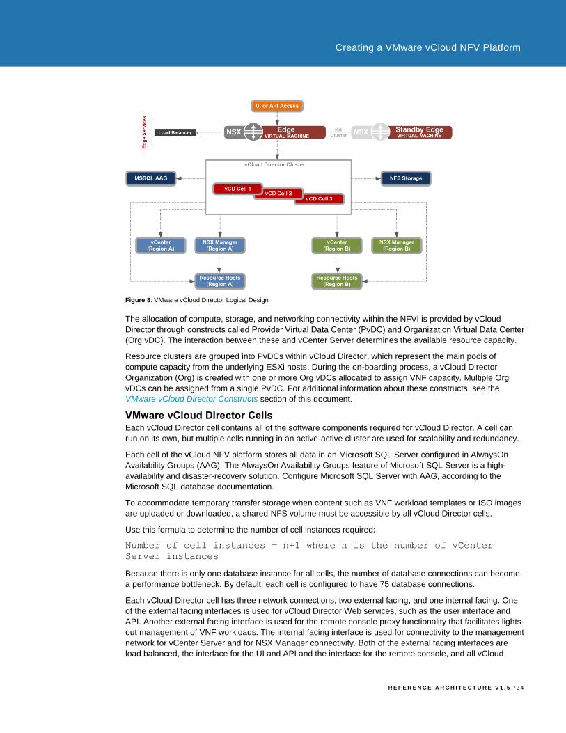
R E F E R E N C E A R C H I T E C T U R E V 1 . 5 / 2 4
Creating a VMware vCloud NFV Platform
Figure 8: VMware vCloud Director Logical Design
The allocation of compute, storage, and networking connectivity within the NFVI is provided by vCloud
Director through constructs called Provider Virtual Data Center (PvDC) and Organization Virtual Data Center
(Org vDC). The interaction between these and vCenter Server determines the available resource capacity.
Resource clusters are grouped into PvDCs within vCloud Director, which represent the main pools of
compute capacity from the underlying ESXi hosts. During the on-boarding process, a vCloud Director
Organization (Org) is created with one or more Org vDCs allocated to assign VNF capacity. Multiple Org
vDCs can be assigned from a single PvDC. For additional information about these constructs, see the
VMware vCloud Director Constructs section of this document.
VMware vCloud Director Cells Each vCloud Director cell contains all of the software components required for vCloud Director. A cell can
run on its own, but multiple cells running in an active-active cluster are used for scalability and redundancy.
Each cell of the vCloud NFV platform stores all data in an Microsoft SQL Server configured in AlwaysOn
Availability Groups (AAG). The AlwaysOn Availability Groups feature of Microsoft SQL Server is a high-
availability and disaster-recovery solution. Configure Microsoft SQL Server with AAG, according to the
Microsoft SQL database documentation.
To accommodate temporary transfer storage when content such as VNF workload templates or ISO images
are uploaded or downloaded, a shared NFS volume must be accessible by all vCloud Director cells.
Use this formula to determine the number of cell instances required:
Number of cell instances = n+1 where n is the number of vCenter
Server instances
Because there is only one database instance for all cells, the number of database connections can become
a performance bottleneck. By default, each cell is configured to have 75 database connections.
Each vCloud Director cell has three network connections, two external facing, and one internal facing. One
of the external facing interfaces is used for vCloud Director Web services, such as the user interface and
API. Another external facing interface is used for the remote console proxy functionality that facilitates lights-
out management of VNF workloads. The internal facing interface is used for connectivity to the management
network for vCenter Server and for NSX Manager connectivity. Both of the external facing interfaces are
load balanced, the interface for the UI and API and the interface for the remote console, and all vCloud
R E F E R E N C E A R C H I T E C T U R E V 1 . 5 / 2 5
Creating a VMware vCloud NFV Platform
Director cells are connected to a shared clustered database.
When configuring vCloud Director behind a load balancer, configure the following settings to respond to the
client’s request with the correct fully qualified domain name (FQDN) or IP address. These settings are
required for the UI and API and console proxy service requests to function:
• VMware vCloud Director must have a public URL
• VMware vCloud Director must have a public console proxy address
• VMware vCloud Director must have a public REST API with a base URL
VMware vCloud Director Constructs VMware vCloud Director abstracts compute, storage, and network resources from an underlying virtualized
infrastructure and provides a new set of constructs that are used to define NFVI tenants and assign
resources to them. This section gives an overview of the vCloud Director terminology and how it maps to the
vCloud NFV platform.
Key VMware vCloud Director terminology: Provider Virtual Data Centers. The Provider Virtual Data Center (PvDC) is a standard container for a pool
of compute, storage, and network resources from a single vCenter server. The requirements of a vCloud
NFV platform solution dictate that the platform must be generic enough to support future VNF requirements.
During deployment, a VNF can leverage one or multiple PvDCs per site, or multiple VNFs can share a single
PvDC with different Org vDCs. As part of the onboarding process, the requirements of each VNF are
assessed.
Organizations. Organizations are the unit of multi-tenancy within vCloud Director. Within the vCloud NFV
platform, a NFVI tenant can be defined in multiple ways. A NFVI tenant can be a VNF provider. Alternatively,
a VNF can be defined per application and can consist of multiple VNF providers who together offer a joint
service. You must identify the necessary level of separation between different VNFs and the creation of
NFVI tenants during the onboarding process. Tenant operations teams handle the creation and
management of organizations.
Organization Virtual Data Center. An Organization Virtual Data Center (Org vDC) is a subgrouping of
compute, storage, and network resources allocated from a PvDC and mapped to an organization. Multiple
Org vDCs can share the resources of the same PvDC, as they do in Figure 9: VMware vCloud Director
Constructs Logical Design. An Org vDC is the deployment environment in which VNF workloads are
deployed and executed.
R E F E R E N C E A R C H I T E C T U R E V 1 . 5 / 2 6
Creating a VMware vCloud NFV Platform
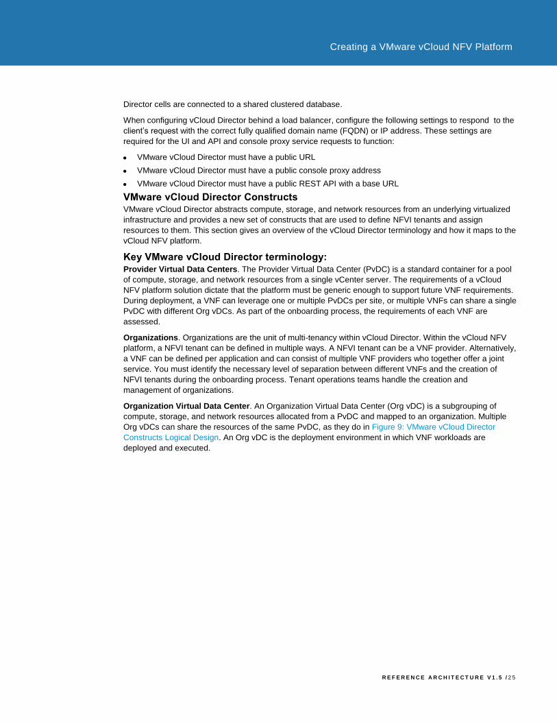
Figure 9 shows a configuration for vCloud Director using PvDC and Org vDC. For vCloud Director
configuration maximums, read the Knowledge Base article VMware vCloud Director 5.5 Configuration
Maximums (2060571).
Figure 9: VMware vCloud Director Constructs Logical Design
NFVI tenants can draw resources from multiple Org vDCs using one of the following resource allocation
models:
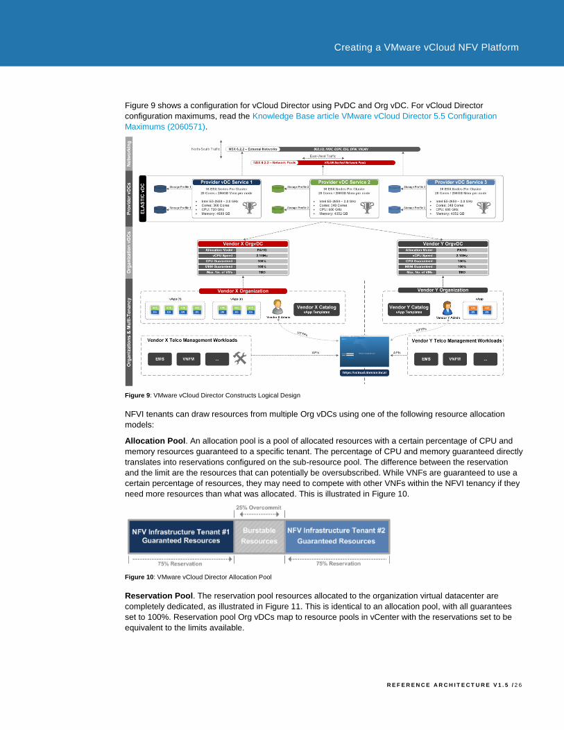
Allocation Pool. An allocation pool is a pool of allocated resources with a certain percentage of CPU and
memory resources guaranteed to a specific tenant. The percentage of CPU and memory guaranteed directly
translates into reservations configured on the sub-resource pool. The difference between the reservation
and the limit are the resources that can potentially be oversubscribed. While VNFs are guaranteed to use a
certain percentage of resources, they may need to compete with other VNFs within the NFVI tenancy if they
need more resources than what was allocated. This is illustrated in Figure 10.
Figure 10: VMware vCloud Director Allocation Pool
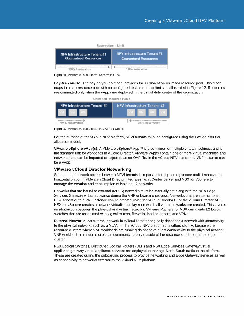
Reservation Pool. The reservation pool resources allocated to the organization virtual datacenter are
completely dedicated, as illustrated in Figure 11. This is identical to an allocation pool, with all guarantees
set to 100%. Reservation pool Org vDCs map to resource pools in vCenter with the reservations set to be
equivalent to the limits available.
R E F E R E N C E A R C H I T E C T U R E V 1 . 5 / 2 7
Creating a VMware vCloud NFV Platform
Figure 11: VMware vCloud Director Reservation Pool
Pay-As-You-Go. The pay-as-you-go model provides the illusion of an unlimited resource pool. This model
maps to a sub-resource pool with no configured reservations or limits, as illustrated in Figure 12. Resources
are committed only when the vApps are deployed in the virtual data center of the organization.
Figure 12: VMware vCloud Director Pay-As-You-Go Pool
For the purpose of the vCloud NFV platform, NFVI tenants must be configured using the Pay-As-You-Go
allocation model.
VMware vSphere vApp(s). A VMware vSphere® App™ is a container for multiple virtual machines, and is
the standard unit for workloads in vCloud Director. VMware vApps contain one or more virtual machines and
networks, and can be imported or exported as an OVF file. In the vCloud NFV platform, a VNF instance can
be a vApp.
VMware vCloud Director Networking Separation of network access between NFVI tenants is important for supporting secure multi-tenancy on a
horizontal platform. VMware vCloud Director integrates with vCenter Server and NSX for vSphere to
manage the creation and consumption of isolated L2 networks.
Networks that are bound to external (MPLS) networks must be manually set along with the NSX Edge
Services Gateway virtual appliance during the VNF onboarding process. Networks that are internal to an
NFVI tenant or to a VNF instance can be created using the vCloud Director UI or the vCloud Director API.
NSX for vSphere creates a network virtualization layer on which all virtual networks are created. This layer is
an abstraction between the physical and virtual networks. VMware vSphere for NSX can create L2 logical
switches that are associated with logical routers, firewalls, load balancers, and VPNs.
External Networks. An external network in vCloud Director originally describes a network with connectivity
to the physical network, such as a VLAN. In the vCloud NFV platform this differs slightly, because the
resource clusters where VNF workloads are running do not have direct connectivity to the physical network.
VNF workloads in resource sites can communicate only outside of the resource site through the edge
cluster.
NSX Logical Switches, Distributed Logical Routers (DLR) and NSX Edge Services Gateway virtual
appliance gateway virtual appliance services are deployed to manage North-South traffic to the platform.
These are created during the onboarding process to provide networking and Edge Gateway services as well
as connectivity to networks external to the vCloud NFV platform.

R E F E R E N C E A R C H I T E C T U R E V 1 . 5 / 2 8
Creating a VMware vCloud NFV Platform
Figure 13: VMware vCloud Director External Networks
Networks created by vSphere for NSX are available for consumption from within vCloud Director through the
use of vCloud Director external networks as shown in Figure 13. VNF connectivity to these external
networks can be achieved by using any of the vCloud Director Org vDC network constructs explained below.
Organization Virtual Data Center Networks. Organization Virtual Data Center Networks (Org vDC)
networks provide Org vDCs with networks to connect to VNF workloads. These Org vDC networks can be
shared across Org vDCs within the same NFVI tenant. This allows VNF workloads in multiple Org vDCs to
communicate with each other by connecting to the same Org vDC network.
Org vDC networks can be created in any of the following ways:
• Internal. Org vDC networks can be internal to the NFVI tenant with no external connectivity.
Figure 14: Internal Org vDC Network
• Routed. Org vDC networks can be routed for connection to an existing VXLAN or VLAN.
Figure 15: Routed Org vDC Network
R E F E R E N C E A R C H I T E C T U R E V 1 . 5 / 2 9
Creating a VMware vCloud NFV Platform
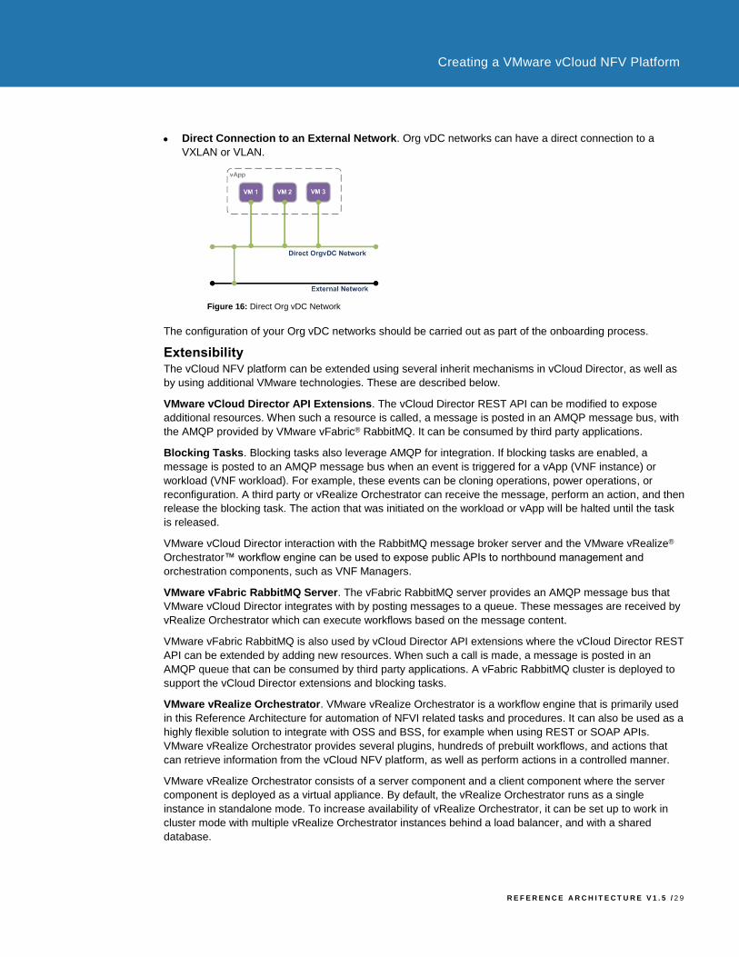
• Direct Connection to an External Network. Org vDC networks can have a direct connection to a
VXLAN or VLAN.
Figure 16: Direct Org vDC Network
The configuration of your Org vDC networks should be carried out as part of the onboarding process.
Extensibility The vCloud NFV platform can be extended using several inherit mechanisms in vCloud Director, as well as
by using additional VMware technologies. These are described below.
VMware vCloud Director API Extensions. The vCloud Director REST API can be modified to expose
additional resources. When such a resource is called, a message is posted in an AMQP message bus, with
the AMQP provided by VMware vFabric® RabbitMQ. It can be consumed by third party applications.
Blocking Tasks. Blocking tasks also leverage AMQP for integration. If blocking tasks are enabled, a
message is posted to an AMQP message bus when an event is triggered for a vApp (VNF instance) or
workload (VNF workload). For example, these events can be cloning operations, power operations, or
reconfiguration. A third party or vRealize Orchestrator can receive the message, perform an action, and then
release the blocking task. The action that was initiated on the workload or vApp will be halted until the task
is released.
VMware vCloud Director interaction with the RabbitMQ message broker server and the VMware vRealize®
Orchestrator™ workflow engine can be used to expose public APIs to northbound management and
orchestration components, such as VNF Managers.
VMware vFabric RabbitMQ Server. The vFabric RabbitMQ server provides an AMQP message bus that
VMware vCloud Director integrates with by posting messages to a queue. These messages are received by
vRealize Orchestrator which can execute workflows based on the message content.
VMware vFabric RabbitMQ is also used by vCloud Director API extensions where the vCloud Director REST
API can be extended by adding new resources. When such a call is made, a message is posted in an
AMQP queue that can be consumed by third party applications. A vFabric RabbitMQ cluster is deployed to
support the vCloud Director extensions and blocking tasks.
VMware vRealize Orchestrator. VMware vRealize Orchestrator is a workflow engine that is primarily used
in this Reference Architecture for automation of NFVI related tasks and procedures. It can also be used as a
highly flexible solution to integrate with OSS and BSS, for example when using REST or SOAP APIs.
VMware vRealize Orchestrator provides several plugins, hundreds of prebuilt workflows, and actions that
can retrieve information from the vCloud NFV platform, as well as perform actions in a controlled manner.
VMware vRealize Orchestrator consists of a server component and a client component where the server
component is deployed as a virtual appliance. By default, the vRealize Orchestrator runs as a single
instance in standalone mode. To increase availability of vRealize Orchestrator, it can be set up to work in
cluster mode with multiple vRealize Orchestrator instances behind a load balancer, and with a shared
database.
R E F E R E N C E A R C H I T E C T U R E V 1 . 5 / 3 0
Creating a VMware vCloud NFV Platform
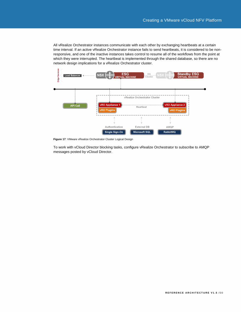
All vRealize Orchestrator instances communicate with each other by exchanging heartbeats at a certain
time interval. If an active vRealize Orchestrator instance fails to send heartbeats, it is considered to be non-
responsive, and one of the inactive instances takes control to resume all of the workflows from the point at
which they were interrupted. The heartbeat is implemented through the shared database, so there are no
network design implications for a vRealize Orchestrator cluster.
Figure 17: VMware vRealize Orchestrator Cluster Logical Design
To work with vCloud Director blocking tasks, configure vRealize Orchestrator to subscribe to AMQP
messages posted by vCloud Director.

R E F E R E N C E A R C H I T E C T U R E V 1 . 5 / 3 1
Creating a VMware vCloud NFV Platform
4.3 NFVI Operations Management Design The NFVI Operations Management components are a functional block in the Management and
Orchestration working domain. These components are responsible to provide and extend visibility for fault,
configuration, accounting, performance, and security (FCAPS) of the NFVI. The VMware implementation of
the vCloud NFV platform expands the capabilities of this functional block through its unique portfolio of
solutions by offering business continuity and disaster recovery capabilities across the MANO working
domain. Over the past decade, VMware has built integrated solutions that enable customers in all industries
to operate large-scale cloud implementations.
For the purpose of the vCloud NFV platform, the NFVI Operations Management tasks are delivered through
the use of the components listed in Table 6. All components are deployed into the management cluster.
COM P O NE N T N AM E DE S C RI P TI ON
VMware vRealize Operations
Manager
VMware vRealize Operations Manager handles performance and
capacity management of the NFVI and VIM components.
VMware vRealize Log Insight
VMware vRealize Log Insight provides real-time log management and
log analysis with machine learning-based intelligent grouping, high-
performance search, and better troubleshooting across physical,
virtual, and cloud environments.
VMware Site Recovery
Manager
VMware Site Recovery Manager is a disaster recovery orchestration
engine for providing predictable failover of management components.
VMware vSphere Replication VMware vSphere Replication provides granular replication of
management virtual machines.
VMware vSphere Data
Protection
VMware vSphere Data Protection provides data protection of the
management components involving the backup and restore of
underlying virtual machines.
Table 6: NFVI Operations Management Components
4.3.1 VMware vRealize Operations Manager
The underlying virtual infrastructure relies on a monitoring solution able to collect data regarding its health,
capacity, availability, and performance. VMware vRealize Operations Manager provides a solution for a
highly scalable, available, and extensible monitoring infrastructure.
VMware vRealize Operations is tightly integrated with DRS. Analytics determine the cross-cluster placement
opportunities for vRealize Operations, while DRS determines the best destination within clusters. The
enhanced integration uses all DRS rules, constraints, and enterprise-class capabilities.
High availability is achieved by deploying a master node and a master replica node to which data is
synchronized automatically. Each node is self-contained and has all the services required for it to operate.
This allows you to deploy additional nodes to scale out the vRealize Operations Manager cluster.

R E F E R E N C E A R C H I T E C T U R E V 1 . 5 / 3 2
Creating a VMware vCloud NFV Platform
Figure 18: VMware vRealize Operations Logical Design
VMware vRealize Operations Management Pack VMware vRealize Operations Manager gathers its data from the adapters connected to source servers. For
this mechanism to work, vRealize Operations Manager is configured to communicate to source servers
using an authorized user account. If the user account has limited access to objects in the source server, it
sees only the data for which the account has permissions. At a minimum, the user account must have read
privileges across the objects to collect. For additional information about VMware vCloud Operations
Solutions, see the VMware vCloud Management Marketplace.
The following vRealize Operations Management Packs are installed to gather metrics across the
management components:
• VMware vRealize® Operations Management Pack™ for vCloud Director
• VMware vRealize® Operations Management Pack™ for vCenter Server
• VMware vRealize® Operations Management Pack™ for NSX
• VMware vRealize® Operations Management Pack™ for Storage
• VMware vRealize® Operations Management Pack™ for Log Insight
• VMware vRealize® Operations Management Pack™ for OpenStack
• VMware vRealize® Operations Management Pack™ for Network Devices
To minimize traffic between the vCenter Server and the vRealize Operations Manager, the vCenter Server
Adapter is installed with a five-minute collection interval.
VMware vRealize Operations Manager Logging Audit logs are used to track configuration changes performed by authenticated users to see who initiated the
change or scheduled a job that performed the change. All audit logs are forwarded to vRealize Log Insight.
VMware vRealize Operations Manager Alerts When alerts are generated in vRealize Operations Manager, they appear in the alert details and object
details, but can also be configured to be sent outside the applications using outbound alert options.
VMware vRealize Operations Manager has the following plug-ins for sending notifications and alerts:
• SMTP to activate email service reports and notifications messages when alerts are raised
• SNMP traps send alerts to an SNMP target
• REST API

R E F E R E N C E A R C H I T E C T U R E V 1 . 5 / 3 3
Creating a VMware vCloud NFV Platform
The decision to use a specific alerting method is implementation-specific and is typically driven by the
external monitoring and management tools available.
4.3.2 VMware vRealize Log Insight
VMware vRealize Log Insight is used to connect to vCenter Servers to collect server events, tasks, and
alarms data. It integrates with vRealize Operations Manager to send notification events.
VMware vRealize Log Insight is deployed using a multi-node HA cluster with a minimum of three virtual
appliances, using the integrated load balancer capabilities. Data is collected using the syslog protocol or
an API. All NSX Manager syslog information, distributed firewall logs, and NSX Edge Services Gateway
virtual appliance gateway virtual appliance Services syslog information is sent to vRealize Log Insight.
Each vCloud Director cell produces logs that persist in the internal database for 90 days. These are sent to
vRealize Log Insight for centralized log access and archiving.
Additional vCloud Director troubleshooting and API access logs are stored locally on the cells. These logs
are produced by the Apache log4j logging utility and can be forwarded by creating an additional appender
on the cell. For additional information, read the Knowledge Base article Enabling Centralized Logging in
VMware vCloud Director (2004564). It is configured for the vCloud Director cells.
VMware vRealize Log Insight Content Pack VMware vRealize Log Insight gathers log events from multiple sources, and through special content packs
delivers solution specific dashboards to perform log analytics using redefined alerts. For additional
information about VMware vRealize Log Insight Solutions, see the VMware vCloud Management
Marketplace.
The following vRealize Log Insight content packs are implemented as part of the vCloud NFV platform:
• VMware vRealize® Log Insight™ Content Pack for vCloud Director
• VMware vRealize® Log Insight™ Content Pack for NSX for vSphere
• VMware vRealize® Log Insight™ Content Pack for vCenter Server
• VMware vRealize® Log Insight™ Content Pack for vRealize Operations Manager
• VMware vRealize® Log Insight™ Content Pack for Microsoft SQL
• VMware vRealize® Log Insight™ Content Pack for Microsoft Windows
VMware vRealize Log Insight Archiving Archiving is primarily a long-term retention tool. The process copies raw data to an external NFS storage.
Archives are much smaller than indexes but require indexing if they are loaded back into the vRealize Log
Insight system. For additional information about vRealize Log Insight archiving, see the VMware vRealize
Log Insight Information page.
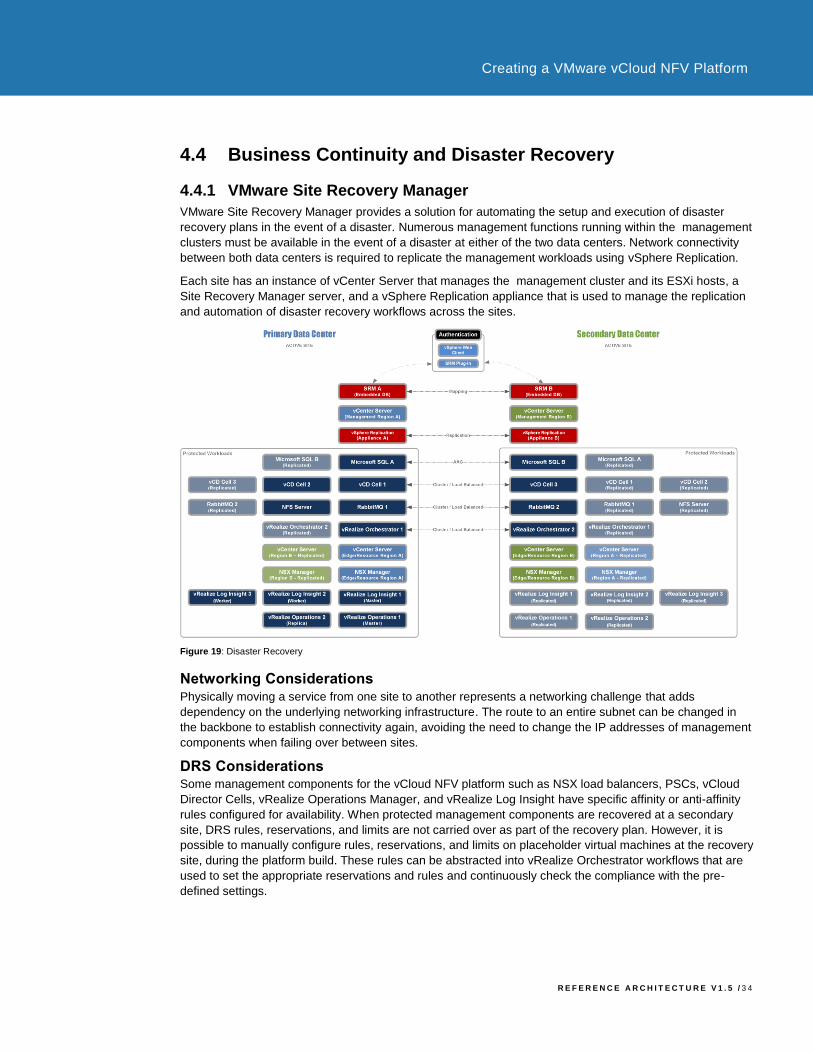
R E F E R E N C E A R C H I T E C T U R E V 1 . 5 / 3 4
Creating a VMware vCloud NFV Platform
4.4 Business Continuity and Disaster Recovery
4.4.1 VMware Site Recovery Manager
VMware Site Recovery Manager provides a solution for automating the setup and execution of disaster
recovery plans in the event of a disaster. Numerous management functions running within the management
clusters must be available in the event of a disaster at either of the two data centers. Network connectivity
between both data centers is required to replicate the management workloads using vSphere Replication.
Each site has an instance of vCenter Server that manages the management cluster and its ESXi hosts, a
Site Recovery Manager server, and a vSphere Replication appliance that is used to manage the replication
and automation of disaster recovery workflows across the sites.
Figure 19: Disaster Recovery
Networking Considerations Physically moving a service from one site to another represents a networking challenge that adds
dependency on the underlying networking infrastructure. The route to an entire subnet can be changed in
the backbone to establish connectivity again, avoiding the need to change the IP addresses of management
components when failing over between sites.
DRS Considerations Some management components for the vCloud NFV platform such as NSX load balancers, PSCs, vCloud
Director Cells, vRealize Operations Manager, and vRealize Log Insight have specific affinity or anti-affinity
rules configured for availability. When protected management components are recovered at a secondary
site, DRS rules, reservations, and limits are not carried over as part of the recovery plan. However, it is
possible to manually configure rules, reservations, and limits on placeholder virtual machines at the recovery
site, during the platform build. These rules can be abstracted into vRealize Orchestrator workflows that are
used to set the appropriate reservations and rules and continuously check the compliance with the pre-
defined settings.
R E F E R E N C E A R C H I T E C T U R E V 1 . 5 / 3 5
Creating a VMware vCloud NFV Platform
Inventory Mappings Inventory mapping provides mapping between virtual machine folders, clusters or resource pools, and
networks on the protected site and their counterparts on the recovery site. All items within a single data
center on the protected site must map to a single data center on the recovery site.
These inventory mapping details are used across both the protected and recovery sites:
• Resource mapping to map the cluster objects at the recovery site.
• Folder mapping to correctly map the folder structure at the recovery site.
• Network mapping to correctly map the management networks at the recovery site.
VNF Recovery Considerations Every vendor must provide a specific strategy for disaster recovery for a VNF that will be managed directly
by the VNF Managers.
4.4.2 VMware vSphere Replication
VMware vSphere Replication is the technology used to replicate virtual machine data between data centers.
It fully supports Virtual SAN. VMware vSphere Replication is deployed as an appliance within the
management cluster and provides a recovery point objective (RPO) of 15 minutes to 24 hours.
The two most important performance metrics that need to be considered when designing or executing a
disaster recovery plan are RPO and recovery time objective (RTO). RPO is the maximum period during
which data can be lost due to a disaster, and it is fulfilled by the replication technology. RTO is a period of
time, usually with an attached service level, during which the business process must be restored. It can
include the time for the recovery itself, testing, and communication to consumers of the service.
Site Recovery Manager and vSphere Replication provide the ability to set the RPO for each individual virtual
machine within a protection group.
Protection Groups A protection group is a group of management components that fail over together at the recovery site during
testing and recovery. All protected management components are placed within a single protection group.
Recovery Plans Recovery Plans are the run books associated with the disaster recovery scenario. A recovery plan
determines which management components are started, what needs to be powered down, which scripts to
run, the start-up order, and the overall automated execution of the failover.
A full site failure is the only scenario that will invoke a disaster recovery. There is no requirement to handle
planned migrations or to move a single failed application within the management cluster. A single recovery
plan is created for the automated failover of the primary site, and the placement of Management
components into priority groups ensures the correct startup order.
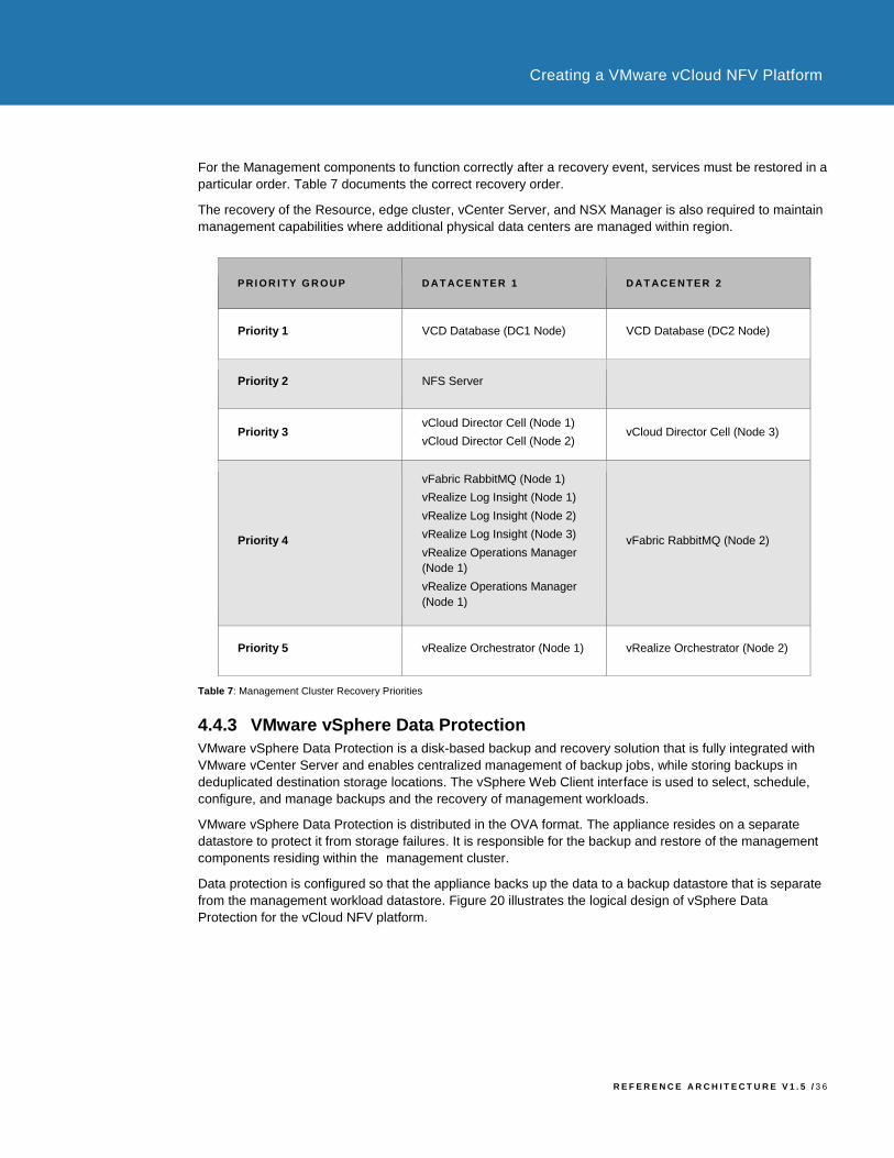
R E F E R E N C E A R C H I T E C T U R E V 1 . 5 / 3 6
Creating a VMware vCloud NFV Platform
For the Management components to function correctly after a recovery event, services must be restored in a
particular order. Table 7 documents the correct recovery order.
The recovery of the Resource, edge cluster, vCenter Server, and NSX Manager is also required to maintain
management capabilities where additional physical data centers are managed within region.
P RI OR I T Y G R OUP D AT ACE N TE R 1 D AT ACE N TE R 2
Priority 1 VCD Database (DC1 Node) VCD Database (DC2 Node)
Priority 2 NFS Server
Priority 3 vCloud Director Cell (Node 1)
vCloud Director Cell (Node 2) vCloud Director Cell (Node 3)
Priority 4
vFabric RabbitMQ (Node 1)
vRealize Log Insight (Node 1)
vRealize Log Insight (Node 2)
vRealize Log Insight (Node 3)
vRealize Operations Manager
(Node 1)
vRealize Operations Manager
(Node 1)
vFabric RabbitMQ (Node 2)
Priority 5 vRealize Orchestrator (Node 1) vRealize Orchestrator (Node 2)
Table 7: Management Cluster Recovery Priorities
4.4.3 VMware vSphere Data Protection
VMware vSphere Data Protection is a disk-based backup and recovery solution that is fully integrated with
VMware vCenter Server and enables centralized management of backup jobs, while storing backups in
deduplicated destination storage locations. The vSphere Web Client interface is used to select, schedule,
configure, and manage backups and the recovery of management workloads.
VMware vSphere Data Protection is distributed in the OVA format. The appliance resides on a separate
datastore to protect it from storage failures. It is responsible for the backup and restore of the management
components residing within the management cluster.
Data protection is configured so that the appliance backs up the data to a backup datastore that is separate
from the management workload datastore. Figure 20 illustrates the logical design of vSphere Data
Protection for the vCloud NFV platform.
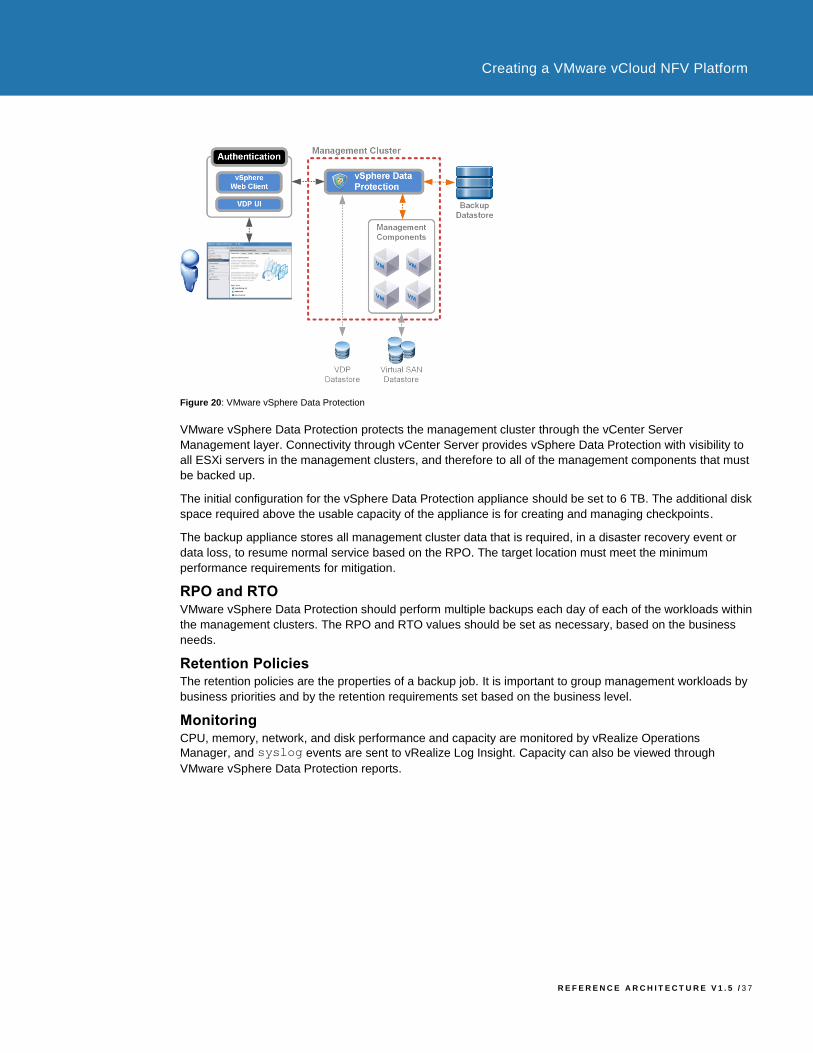
R E F E R E N C E A R C H I T E C T U R E V 1 . 5 / 3 7
Creating a VMware vCloud NFV Platform
Figure 20: VMware vSphere Data Protection
VMware vSphere Data Protection protects the management cluster through the vCenter Server
Management layer. Connectivity through vCenter Server provides vSphere Data Protection with visibility to
all ESXi servers in the management clusters, and therefore to all of the management components that must
be backed up.
The initial configuration for the vSphere Data Protection appliance should be set to 6 TB. The additional disk
space required above the usable capacity of the appliance is for creating and managing checkpoints.
The backup appliance stores all management cluster data that is required, in a disaster recovery event or
data loss, to resume normal service based on the RPO. The target location must meet the minimum
performance requirements for mitigation.
RPO and RTO VMware vSphere Data Protection should perform multiple backups each day of each of the workloads within
the management clusters. The RPO and RTO values should be set as necessary, based on the business
needs.
Retention Policies The retention policies are the properties of a backup job. It is important to group management workloads by
business priorities and by the retention requirements set based on the business level.
Monitoring CPU, memory, network, and disk performance and capacity are monitored by vRealize Operations
Manager, and syslog events are sent to vRealize Log Insight. Capacity can also be viewed through
VMware vSphere Data Protection reports.
R E F E R E N C E A R C H I T E C T U R E V 1 . 5 / 3 8
Creating a VMware vCloud NFV Platform
Authors and Contributors
• Pradip Kadam, Solution Consultant, NFV Solution Team, VMware
• Indranil Bal, Solution Consultant, NFV Solution Team, VMware
VMware, Inc. 3401 Hillview Avenue Palo Alto CA 94304 USA Tel 877-486-9273 Fax 650-427-5001 www.vmware.com
Copyright © 2015 VMware, Inc. All rights reserved. This product is protected by U.S. and international copyright and intellectual property laws. VMware products are covered by one or more patents listed at http://www.vmware.com/go/patents.
VMware is a registered trademark or trademark of VMware, Inc. in the United States and/or other jurisdictions. All other marks and names mentioned herein may be trademarks of their respective companies.