Embed Size (px)
Citation preview

In This Chapter
511
15
Creating a Layout to Plot
A layout is a paper space environment that simulates
a sheet of paper and provides a predictable plotting
setup. In a layout, you can create and position
viewport objects, and you can add a title block
or other geometry. You can create multiple layouts
in a drawing to display various views, each of
which can contain different plot scales and paper
sizes. Each layout displays the drawing as it will
be plotted on the sheet of paper.
■ Using model space and paper space environments
■ Creating a layout to plot
■ Working with layouts
■ Using layout templates
■ Determining layout settings (page setups)
■ Designing and editing floating viewports
■ Working with nonrectangular viewports

512 | Chapter 15 Creating a Layout to Plot
Using Model Space and Paper Space
As you design your model drawing and prepare it for plotting, you can use model space and paper space just as with previous AutoCAD® releases. Using AutoCAD 2000, however, the environment you use to layout and prepare your drawing for plotting is much more visual. At the bottom of the drawing window are tabs that include the Model tab and one or more layout tabs. Model space can be accessed from the Model tab or by making a floating viewport in a layout current. The Model tab is where you spend most of your time creating and editing your drawing. When you are in the Model tab, you are always working in model space. You can divide the Model tab into tiled viewports to represent various views of your model. For more information about creating and using tiled viewports in model space, see “Using Tiled Viewports” on page 223. You can also plot your drawing from the Model tab.
When you are ready to setup your drawing for plotting, you can use a layout tab. Each layout tab provides a paper space drawing environment in which you can create viewports and specify page settings for each layout you want to plot. Page settings are just plot settings that are saved with the layout. As you designate page settings for a layout, you can choose to save and name the page settings for one layout, then apply that named page setup to another lay-out. You can also create a new layout from an existing layout template (.dwt or .dwg) file into a new layout.
Typically, when you begin designing a layout environment to plot, you step through the following process:
■ Create a model drawing.■ Configure a plotting device.■ Activate or create a layout.■ Specify layout page settings such as plotting device, paper size, plot area,
plot scale, and drawing orientation.■ Insert a title block.■ Create floating viewports and position them in the layout.■ Set the view scale of the floating viewports.■ Annotate or create geometry in the layout as needed.■ Plot your layout.

Working in Paper Space | 513
Switching Between Model Space and Paper Space
After you’ve created your layout and designed the floating viewports, you can continue working on your drawing from the Model tab or a layout tab. You can change the layout page settings to plot to a different size paper or at a different scale.
To make the Model tab current, choose the Model tab or enter model atthe command line. To move from the Model tab to paper space, choose the Layout1 tab or enter paper at the command line.
While in a layout, you can work in paper space or you can work in model space by making a viewport current. To make a viewport current, double-click the pointing device while the cursor is over a viewport. To make paper space current, double-click over any area in the layout outside of a floating viewport. You can also switch between model space and paper space in a layout by choosing either Paper or Model from the status bar. The last active viewport is made current when switching to model space by choosing Model from the status bar.
Working in Paper Space
Paper space represents the paper on which you arrange the drawing prior to plotting. With AutoCAD 2000, single or multiple paper space environments can be easily designed and manipulated using layout tabs. Layouts are acces-sible by choosing a layout tab at the bottom of the drawing area. Each layout represents an individual plot output sheet, or an individual sheet in a draw-ing project. As you create a new layout, you can add floating viewports to plot. Once you’ve created floating viewports in a layout, you can apply dif-ferent scales to each view within the viewport, and specify different visibil-ity for layers in the viewport.
If you want to use plot styles, you can also attach a plot style table to a layout or viewport. A plot style table contains all of the plot styles that you want to apply to the objects in the drawing when you plot. For detailed information about creating plot styles and plot style tables, and attaching them to your layout or viewport, see “Creating a Plot Style Table” on page 557.

514 | Chapter 15 Creating a Layout to Plot
Using a Layout Tab
Choosing a layout tab places you into the paper space environment. A rect-angular outline (shadow) indicates the paper size of the currently configured plotting device. The margins displayed within the paper indicate the print-able area of the paper.
You can control the display of the paper background in the layout from the Display tab in the Options dialog box. Also on the Display tab in the Options dialog box, you can control whether the Page Setup dialog box is automati-cally displayed the first time you select a layout.
After creating an initial layout for your project, you can choose to create multiple layouts to display various views for plotting.
Related When a paper space layout is made current for the first time, and a default viewport is created in the layout, the VIEWRES for this initial viewport is the same as the VIEWRES for the Model tab viewport.
To create multiple layouts
1 On the layout tab, right-click to display the shortcut menu.
2 From the shortcut menu, choose New Layout.
To rename a layout tab, choose Rename from the shortcut menu.
paper image
printable area
single viewport

Working in Paper Space | 515
Using the Layout Wizard to Specify Layout Settings
Before you use the Layout wizard to specify a layout environment, you should make sure that you have access to a configured plotter. To add or configure a new Windows system plotter, you can choose the Microsoft
Printers folder in the Windows Control Panel, then choose Add Printer. To add a nonsystem plotter configuration, choose Add or Configure Plotters on the Plotting tab in the Options dialog box.
When you are ready to work in a layout, you have the option of specifying the layout environment using the Create Layout wizard. You can access the Create Layout wizard from the Tools menu by choosing Wizards, or by en-tering layoutwizard on the command line.
Using the Create Layout wizard, you can specify a plot device, indicate a paper size based on the plotting device you have specified, specify the orientation of the drawing on the paper, select a title block to use for the layout, and deter-mine a viewport setup.
The plotting devices provided through the wizard are the devices that are currently configured. If you want to configure a new plotter, you must choose the Microsoft Printer folder in the Windows Control Panel, then choose Add Printer.
Each layout tab stores plot settings such as paper size, image orientation, plot scale, and plot offset. After selecting a plotting device for the current layout, you are presented with a list of paper sizes that are available for the selected plotter.

516 | Chapter 15 Creating a Layout to Plot
You can also determine the units of paper using the Layout wizard. If you designated your drawing units to represent 1 unit = 1 inch, you should specify paper units to be inches in the wizard, even if you are selecting an ISO size sheet of paper. If one unit represents 1 millimeter in your drawing, you should set the paper units in the Layout wizard to millimeters. The width and height of the paper size are displayed in the wizard according to the units selected.
To select a title block, you are presented with a list of predefined ANSI (American National Standards Institute) and ISO (International Standards Organization) AutoCAD title blocks from which to choose. As you select a title block from the list, that title block is displayed in the preview image. You can choose to either insert the selected title block or attach it as an ex-ternal reference.
When you select a title block, it is recommended that you choose a title block that matches the specified paper units, or else the title block will not fit the selected paper size. ANSI title blocks are drawn in inches, and ISO, DIN, and JIS title blocks are drawn in millimeters. An ANSI A title block is approximately 10 × 8 units in size. If it is inserted into a layout with an A4 size of paper set to millimeters, the paper size will be 297 x 210 units, and the title block will be too small.
NOTE The printable area for some plotting devices may be too small to fit a standard title block onto its corresponding size sheet of paper. For example, an ANSI D size title block may not always fit in the printable area of a D size sheet of paper.
To define the number of viewports for the current layout, you have the op-tion of selecting a single viewport, a standard set of engineering views, or an array of viewports. A standard 3D engineering configuration is a 2 × 2 array consisting of top, front, side, and isometric views. If you select Array, you must also specify the rows and columns for the array. The default is 2 × 2.
drawing drawing with title block and border

Working with Layouts | 517
The default viewport scale is Scaled to Fit. If you specify another scale factor, the view will be centered based on the extents of the model space geometry. The default layout plot scale is 1:1.
After you’ve created a layout, you can modify the layout by moving the viewport in the drawing, adding geometry to the layout, or by choosing Page Setup from the File menu.
Working with Layouts
After you complete a drawing model, you can begin creating a layout to plot by choosing a layout tab. When you choose a layout tab for the first time in a drawing session, a single viewport is displayed, and a sheet with margins indicates the paper size of the currently configured plotter and printable area of the paper. AutoCAD displays the Page Setup dialog box, in which you specify layout and plot device settings. Setting the plot set-tings and using Preview, you can visualize the resulting layout without ac-tually plotting. The layout settings you specify are stored with the layout.
If you don’t want the Page Setup dialog box to be displayed each time you begin a new drawing layout, you can clear Show Page Setup Dialog for New Layouts on the Display tab in the Options dialog box. If you don’t want AutoCAD to automatically create a viewport for each new layout, you can clear Create Viewport in New Layouts on the Display tab in the Options dialog box.
Once you’ve created a layout, you can delete, rename, move, or copy the layout by right-clicking the layout tab, and then choosing an option from the shortcut menu.
To switch from model space to a layout
■ After creating a drawing in model space, choose the Layout1 tab.
A single viewport containing the model drawing is displayed. The Page Setup dialog box is also displayed, in which you can specify a plotter and page setup.
To set up the plotting environment
1 From the File menu, choose Page Setup.
2 In the Page Setup dialog box, enter a name for the layout you are preparing for plotting.
518 | Chapter 15 Creating a Layout to Plot
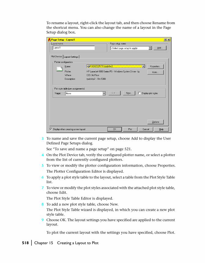
To rename a layout, right-click the layout tab, and then choose Rename from the shortcut menu. You can also change the name of a layout in the Page Setup dialog box.
3 To name and save the current page setup, choose Add to display the User Defined Page Setups dialog.
See “To save and name a page setup” on page 521.
4 On the Plot Device tab, verify the configured plotter name, or select a plotter from the list of currently configured plotters.
5 To view or modify the plotter configuration information, choose Properties.
The Plotter Configuration Editor is displayed.
6 To apply a plot style table to the layout, select a table from the Plot Style Table list.
7 To view or modify the plot styles associated with the attached plot style table, choose Edit.
The Plot Style Table Editor is displayed.
8 To add a new plot style table, choose New.
The Plot Style Table wizard is displayed, in which you can create a new plot style table.
9 Choose OK. The layout settings you have specified are applied to the current layout.
To plot the current layout with the settings you have specified, choose Plot.

Working with Layouts | 519
NOTE To display the plot styles you have applied to an object, select Display Plot Styles, choose OK, and then enter regen on the command line. See “Under-standing Plot Styles” on page 548.
Command line PAGESETUP
Shortcut menu Right-click the layout tab and choose Page Setup.
To create a layout to plot
1 Before you begin creating a layout to plot, specify the plotting device. To add a new plotter configuration, choose Plotter Manager from the File menu.
2 Choose the layout tab you want to plot.
3 From the File menu, choose Page Setup (if the Page Setup dialog box isn’t already displayed).
4 In the Page Setup dialog box on the Layout Settings tab, specify the paper size, paper units, and drawing orientation.
If the PAPERUPDATE system variable is set to 1, you are prompted if the lay-out’s existing paper size is not supported by the plotting device you have selected. The paper size is automatically updated to reflect the default paper size of the selected plotting device.

520 | Chapter 15 Creating a Layout to Plot
5 Under Plot Area, select the area you want to plot. The default setting is Lay-out for the layout tab and Display for the Model tab.
To define an area in the layout to plot, select Window, and then choose the Window button to the right. Use your pointing device to define the bound-ary of the area in the drawing you want to plot.
For detailed information about each of the plot area settings, see “Setting the Plot Area” on page 528.
6 Under Plot Scale, either select from the list of standard scales, or enter a cus-tom scale. If you select a standard scale, that scale is displayed at Custom.
The default scale setting for a layout is 1:1. The default scale setting for a model is Scaled to Fit.
7 To scale lineweights proportionately with the plot scale, select Scale Line-weights.
Typically, the plot scale is 1:1. However, if you plot at half scale, the plot scale would be 1:2, and the lineweight would be scaled proportionately.
8 Under Plot Offset, enter the X and Y offset values to specify an offset from the lower-left corner of the printable area. The values you enter are calculated automatically to center the plot.
9 Under Plot Options, select or clear Plot with Lineweights to control whether lineweights are plotted.
10 Select Plot with Plot Styles to include the plot style properties assigned to the layout or viewport.
For more information about plot style tables, see “Understanding Plot Styles” on page 548.
11 Choose OK.
The settings you specified are applied to the current layout. To plot the cur-rent layout with the settings you specified, choose Plot.
Command line PAGESETUP
Related LIMITS controls the layout paper margins according to the selected paper size. However, when paper space is active, and you’ve set paper mar-gins using the Display tab on the Options dialog box, then any settings you apply to the LIMITS command are read-only and won’t apply to the layout.
Shortcut menu Right-click the layout tab to create a new layout, use an existing template from which to create a layout, delete or rename a layout, move or copy a layout, select all layouts, or plot a layout.
When you are ready to plot the layout, see “Plotting in AutoCAD 2000” on page 550.

Working with Layouts | 521
Saving and Naming a Page Setup
After creating a layout page setup, you can save and name the setup, and then choose to apply it to the current layout or to another layout. By saving a number of page setups, you can also choose to plot one layout in many different ways. For example, you may want to specify a layout to plot at a 1:1 scale on a C-size sheet of paper and also specify the same layout to plot at a 1:2 scale on an A-size sheet of paper. By saving and naming each of these page setups, you can easily apply either of the user-defined page setups to the layout before plotting.
To save and name a page setup
1 From the File menu, choose Page Setup.
2 In the Page Setup dialog box, choose the Layout Settings tab and change set-tings as necessary.
For information on how to specify layout settings, see “To create a layout to plot” on page 519.
3 At Page Setup Name, choose Add.
4 In the User Defined Page Setups dialog box, enter a name for the page setup.
To edit the page setup name directly, choose F2. To delete or rename a user-defined page setup, select a name from the list, then right-click and choose Delete or Rename.
5 Choose OK.
The name you enter is displayed as the current name in the Page Setup dialog box.
Command line PAGESETUP
Importing a Named Page Setup
Once you have saved and named page setups in one drawing, you can import those page setups into another drawing.
To import a named page setup
1 At the Command prompt, enter psetupin.
2 In the Select File dialog box, select the drawing (DWG) file from which you want to import the named page setup.
3 In the Import User Defined Page Setup(s) dialog box, select the named page setup you want to import. The dialog box indicates whether it is a model or layout page setup.
4 Choose OK.
The page setups are imported and can be applied to a layout in the current drawing.
Command line -PSETUPIN

522 | Chapter 15 Creating a Layout to Plot
Moving or Copying a Layout
Layout tabs can be moved or copied and placed after the currently specified layout. The Model tab cannot be moved or copied.
To move a layout tab
1 Right-click the layout tab, and from the shortcut menu, choose Move.
2 In the Move or Copy dialog box, from the list, select where you want to place the currently selected layout.
3 Choose OK.
To copy a layout, select Create a Copy. By default, the Copy option is cleared.
Using a Layout Template
A layout template is simply a layout imported from a DWG or DWT file. When you create a layout, you can choose to apply the information from an existing template. AutoCAD provides sample layout templates to use when designing a new layout environment. When creating a new layout based on a layout template, the paper space geometry and page settings in the existing template is used in the new layout. Thus, the layout geometry, including any viewport objects, is displayed in paper space. You can choose to keep any of the existing geometry from the template you import, or you can delete the geometry. No model space geometry is imported.
AutoCAD provides layout templates that are identified with a .dwt file exten-sion. However, any layout template from any drawing can be imported into the current drawing.
Typically, when you insert a drawing or template file into a new layout, all of the symbol table and block definition information that was saved with the source drawing or layout template will be inserted into the new layout. However, if you save the source template using the LAYOUT Save Template option, any unreferenced symbol table and block definition information is not saved with the layout template. You can then use the Insert From Tem-plate option to create new layouts in your drawings. By using this method to save and insert a layout template, you can avoid having to eliminate un-necessary symbol table information.
If you have drawings created in a previous release of AutoCAD, you can import specific layout and plot setting information saved in a PCP (partial plot configuration) file or a PC2 (complete plot configuration) file to apply to the current layout. PCP and PC2 files contain plot setting information that

Using a Layout Template | 523
was saved in previous versions of AutoCAD. Plot setting information that can be imported from a PCP or PC2 file includes plot area, rotation, plot offset, plot optimization, paper size, and scale.
To use an existing layout template
1 From the Insert menu, choose Layout ➤ Layout from Template.
2 In the Select File dialog box, select a drawing template file from the list.
3 Choose Open.
4 In the Insert Layout dialog box, select the layout template from the list, then choose OK.
A new layout is created using the layout template you selected. The new lay-out is automatically assigned the name Layout with the next number in the sequence, along with the name of the imported layout attached.
Command line -LAYOUT
Shortcut menu Right-click the layout tab and choose From Template.
NOTE If you insert a layout template from another drawing, and all the sym-bol table definitions saved in the source template you are inserting are written to the new layout, you can use PURGE to eliminate the symbol table and block definitions from the new layout.
Using PCP/PC2 Settings in a Layout Template
If you are working with drawings created in an earlier release of AutoCAD, you can choose to import layout and plot settings contained in a previously saved PCP or PC2 file and apply them to the current layout. Settings that are saved in a PCP or PC2 file include
■ Plot Area■ Rotation■ Paper Size■ Plot Scale■ Plot Origin■ Plot Offset
In addition, a PC2 file also contains any resolution information that has been modified by a plotter calibration. Pen assignment information can also be imported and saved in a plot style table using the Plot Style Table wizard. For more information about saving pen assignments to a plot style table, see “Creating a Plot Style Table” on page 557.

524 | Chapter 15 Creating a Layout to Plot
To import plotting device and pen settings information, you can use the Import PCP/PC2 Settings wizard to choose a PCP or PC2 file whose settings you want to import. You can also choose to modify any of the imported set-tings using the Page Setup dialog box.
To import PCP or PC2 settings into the current layout
1 At the Command prompt, enter pcinwizard.
2 In the Import PCP/PC2 Settings wizard, select the PCP or PC2 file whose settings you want to import into the current layout template.
Saving a Layout Template
Any drawing can be saved as a template drawing, and all of the geometry and layout settings can be saved to a DWT file. You can save a layout to a DWT file by selecting the Save option from the LAYOUT command. The template file is saved in the drawing template file directory as defined in the Options dialog box.
When you create a new layout template, any referenced symbol definitions are saved with the template; the referenced symbol definitions are imported as part of the layout settings if you import this template into a new layout. It is recommended that you use the Save option of the LAYOUT command to create a new layout template. When you use the Save option, unused symbol table definitions are not saved with the file; they are not added to the new layout where you are importing the template.
To save a layout template
1 At the Command prompt, enter layout.
2 At the prompt, enter sa to Save the current layout template. Respond to the prompt asking for the name of the layout you are saving.
3 In the Create Drawing File dialog box, enter a name for the drawing template file you are saving.
4 At Save as Type, select Drawing Template File (.dwt).
5 Choose Save.

Determining Layout Settings | 525
Inserting a Layout Using AutoCAD DesignCenter
Using AutoCAD DesignCenter™ dockable control, you can drag and drop a lay-out with its geometry into another layout within the current drawing. You can use the following methods to insert a layout using AutoCAD DesignCenter:
■ Select a layout from the AutoCAD DesignCenter list, then drag and drop it into a new layout.
■ Select a layout from the AutoCAD DesignCenter list, then right-click and choose Copy from the shortcut menu. Then from the Edit menu, choose Paste.
■ Double-click on a layout from the AutoCAD DesignCenter list.
When you use AutoCAD DesignCenter to insert one layout into another lay-out, a new layout is created that includes all of the geometry, symbol tables, and block definitions from the source layout. To eliminate any unnecessary symbol table or block definition information from the new layout, use the PURGE command.
You can also insert a layout template (.dwt file) from AutoCAD DesignCenter using the Open option from the File menu. When you insert a layout tem-plate in this way, any unused symbol table and block definitions are not cop-ied with the template; you don’t need to purge any unnecessary information from the new layout you are creating.
Related For more information about purging unnecessary block definitions from layouts, see the Insert Template and Save Template options of the LAYOUT command in the AutoCAD Command Reference.
Determining Layout Settings
Layout settings, which are also referred to as page setups, control the final plotted output. These settings affect the plot device, paper size, plot scale, plot area, plot origin, and the drawing orientation. Understanding how to use layout settings ensures that the layout plots as expected. All of the set-tings for a layout can be changed and saved to the layout, without actually plotting, using the Page Setup dialog box. You can also choose to import lay-out settings from a PCP or PC2 file into the current layout.

526 | Chapter 15 Creating a Layout to Plot
Selecting a Paper Size
You can select a paper size from a standard list and indicate inches or milli-meters. The paper sizes available in the list are determined by the plot de-vice that is currently configured. If your plotter is configured for raster out-put, you must specify the output size in pixels. You can add custom paper sizes using the PC3 Editor (see “Understanding Plotter Configurations” on page 549).
The default paper size is determined when you add and configure a new plotter. If you are using a system printer, the paper size is determined by the document defaults that are set in the Windows Control Panel. The default paper size is displayed in the Page Setup dialog box when you are creating a new layout for that configured device. If you change the paper size in the Page Setup dialog box, the new paper size is saved with the layout, and over-rides the size saved in the plotter configuration (PC3) file.
To select a paper size
1 From the File menu, choose Page Setup.
2 In the Page Setup dialog box, choose the Plot Settings tab.
3 Select a paper size from the list of sizes available for the configured device.
4 Choose OK.
Command line PAGESETUP
Shortcut menu Right-click a layout tab and choose Page Setup.
Determining the Drawing Orientation
You can specify the orientation of the drawing on the paper using the Land-scape and Portrait settings. Landscape orients the drawing on the paper so that the long edge of the paper is horizontal, and Portrait orients the paper so that the short edge is horizontal. Changing the orientation creates the effect of rotating the paper underneath the drawing. In AutoCAD Release 14, you changed the drawing orientation by specifying a plot rotation.
Although you can specify the drawing orientation in both the Page Setup dialog box and the Plot dialog box, the Page Setup settings are always saved and reflected in the layout. In the Plot dialog box, you can override the page setup settings for a single plot; however, the settings you apply are not saved in the layout. To save the settings you apply using the Plot dialog box, select Save Changes to Layout on the Plot Device tab.
If you change the drawing orientation, the plot origin remains in the lower-left corner of the rotated plot area. See “Adjusting the Plot Origin” on page 527.

Determining Layout Settings | 527
To plot an image in portrait or landscape orientation
1 From the File menu, choose Page Setup.
2 In the Page Setup dialog box, choose the Plot Settings tab.
3 If your drawing is horizontal, select Landscape. If your drawing is vertical, select Portrait.
4 Choose OK.
Command line PAGESETUP
Shortcut menu Right-click a layout tab and choose Page Setup.
To change the drawing orientation
1 From the File menu, choose Page Setup.
2 In the Page Setup dialog box, choose the Plot Settings tab.
3 To rotate a horizontal drawing, select Portrait. To rotate a vertical drawing, select Landscape.
To rotate 180 degrees, select either Portrait or Landscape, and then select Plot Upside-Down.
4 Choose OK.
Adjusting the Plot Origin
The plot origin is the lower-left corner of the specified plotted area. Typically, the plot origin is set to 0,0. However, you can center the plot on the sheet of paper by selecting Center the Plot in the Page Setup dialog box. Centering the plot alters the plot origin.
If you want to move the drawing relative to the lower-left corner of the paper, specify positive or negative values for the plot offset. To offset the plot below the lower-left corner, enter negative values. This may result in the plot area being clipped.
homeposition
lower-left corner of paper
plot with origin –1.0, –0.5plot with origin 0,0

528 | Chapter 15 Creating a Layout to Plot
To offset the plot origin
1 From the File menu, choose Page Setup.
2 In the Page Setup dialog box, choose the Plot Settings tab.
3 Under Plot Offset, enter a value in units for X or Y or both.
The origin is offset by the number of units you enter. A positive value moves the origin up and to the right. A negative value moves the plot origin down and to the left.
4 Choose OK.
Command line PAGESETUP
Shortcut menu Right-click a layout tab and choose Page Setup.
Setting the Plot Area
When you prepare to plot from the Model tab or a layout tab, you can specify the plot area to determine what will be included in the plot. When you create a new layout, the default option is Layout. Layout plots all geometry within the margins of the specified paper size. The plot origin is calculated from 0,0, which is at the lower-left corner of the margins.
The Display option plots all the geometry displayed in the drawing area.
If you have imported a drawing that was saved in paper space in the format of a previous AutoCAD release, Plot Area defaults to Extents and Plot Scale defaults to Scaled to Fit.
To set the plot area and adjust the display
1 From the File menu, choose Page Setup.
2 In the Page Setup dialog box, choose the Plot Settings tab.
3 Under Plot Area, select one of the following options:
■ Layout: Prints all geometry within the margins of the paper. This option is only available from a layout tab.
■ Limits: Prints or plots the current drawing limits. This option is only avail-able from the Model tab.
■ Extents: Plots all objects in the drawing.■ Display: Plots all geometry displayed in the drawing area.■ View: Prints or plots a saved view. Select the View option, and then choose
the View button to display the Named View dialog box and choose a named view.
■ Window: Plots the geometry in the area you define. Select the Window option, and then choose the Window button and respond to the prompts to define the area.
Determining Layout Settings | 529
4 To remove hidden lines when plotting from the current viewport on the Model tab, select Hide Lines. When you are plotting a layout, only the objects in paper space are hidden.
5 Choose OK.
Command line PAGESETUP
NOTE To specify displaying hidden lines for a model space viewport in a lay-out, you must set the HIDEPLOT property of the viewport object.
Setting the Plot Scale
Generally, you draw objects at their actual size. When you plot the drawing, you can either specify a precise scale or fit the image to the paper. To specify a scale, you can enter the ratio of plotted units to drawing units, or you can enter a standard or custom plot scale.
When you are reviewing an early draft view, a precise scale is not always important. You can use the Scaled to Fit option to plot the view at the largest possible size that fits the paper.
To set the plot scale
1 From the File menu, choose Page Setup.
2 In the Page Setup dialog box, choose the Plot Settings tab.
3 Under Scale, select a scale from the list.
The default scale when plotting a layout is 1:1. To set a custom plot scale, enter a plot scale under Custom.
4 Choose OK.
Command line PAGESETUP
Shortcut menu Right-click a layout tab and choose Page Setup.
Setting the Lineweight Scale
Lineweights can be scaled proportionately in a layout with the plot scale. Typically, lineweights specify the linewidth of plotted objects and are plotted with the linewidth size regardless of the plot scale. Most often, you use the default plot scale of 1:1 when plotting a layout. However, if you want to plot an E-size layout that is scaled to fit on an A-size sheet of paper, for example, you can specify lineweights to be scaled in proportion to the new plot scale.

530 | Chapter 15 Creating a Layout to Plot
To set the lineweight scale
1 From the File menu, choose Page Setup.
2 In the Page Setup dialog box, choose the Plot Settings tab.
3 Under Plot Scale, select Scale Lineweights.
4 Choose OK.
The lineweights in the current layout are scaled in proportion to the desig-nated plot scale. When you are working in the Model tab, this option is not available.
Command line PAGESETUP
Shortcut menu Right-click a layout tab and choose Page Setup.
System variables Setting the lineweight scale in this manner changes the value of LWSCALE.
Creating Floating Viewports
When you are composing a layout, you can consider viewports as objects with a view into model space that you can move and resize. Floating view-ports can be overlapping or separated from one another. Because floating viewports are AutoCAD objects, you cannot edit the model while arranging the layout in paper space. To edit the model you must switch to model space using one of the following methods:
■ Choose the Model tab.■ Double-click over the floating viewport. On the status bar, Paper changes
to Paper.■ Click Paper on the status bar to return to the floating viewport that was
last current.
When you make a viewport in a layout current, you are then working in model space in a floating viewport. Edits in model space is reflected in all paper space viewports.
One benefit to using floating viewports is that you can selectively freeze lay-ers in each viewport. By freezing layers, you can view different geometry in each floating viewport. You can also specify different views to display by pan-ning and zooming in the viewport.
As you create and place floating viewports, any plot style table that is attached to the layout is automatically attached to the floating viewports you are creating. If you want to attach a different plot style table to each floating view-port, you select the viewport you want to modify, and then choose the Prop-erties window. See “Attaching Plot Style Tables to Viewports” on page 537.

Creating Floating Viewports | 531
Switching Between Paper Space and Floating Viewports
When you are working in a layout, you can either work in a floating view-port, which is a view into model space, or you can work in the paper space layout outside the viewport. In paper space, you can add annotations or other graphical objects that emphasize a given part of a floating (model space) viewport. Objects you add in paper space do not change the model or other layouts.
To switch between a paper space layout and a floating viewport
■ Click Paper on the status bar.
Clicking Paper on the status bar switches you between paper space and the last current viewport. To return to the paper layout, click Model on the status bar. On the status bar Model changes to Paper.
Placing Floating Viewports in a Layout
You can create a single viewport that fits the entire drawing area or place multiple viewports in the layout. Using the Viewports dialog box, you can insert a variety of standard or named viewport configurations in the layout. The configuration you choose depends on how you plan to view and ulti-mately plot the drawing model.
The following illustrations display various configuration options.
single viewport standard engineering viewports
arrayed viewports

532 | Chapter 15 Creating a Layout to Plot
To create a floating viewport
1 Choose a layout tab.
2 From the View menu, choose Viewports ➤ New Viewports.
3 In the Viewports dialog box, select a viewport configuration from the list.
4 Under Setup, select either 2D or 3D.
When you select 3D, a set of standard 3D views are applied to each viewport in the configuration.
5 Under Viewport Spacing, select the amount of spacing you want to add between the configured floating viewports.
6 To change a view, select a viewport in the preview image, and then, under Change View To, select a view from the list of standard viewport configurations.
The list includes top, bottom, front, back, left, right, and isometric views, along with any named views that are saved in the drawing. The selected view is displayed under Preview.
You can change the view that is generated in each viewport by selecting the viewport in the preview image, and then selecting a view from the list.
7 Choose OK.
Command line VPORTS

Creating Floating Viewports | 533
NOTE You cannot save and name a viewport configuration that you create in a layout. You can only save tiled (model space) viewport configurations to be placed in a layout.
Placing Saved Viewport Configurations in a Layout
A tiled viewport configuration that you saved and named in the Model tab, can be placed in a layout. When you save and name a viewport configura-tion, the name is added to the viewport configuration. See “Saving Viewport Configurations” on page 228.
To place a named viewport into a layout
1 On the layout tab, from the View menu, choose Viewports ➤ New Viewports.
2 In the Viewports dialog box, choose the Named Viewports tab.
3 Select the named viewport configuration from the list and choose OK.
4 In the layout, specify a location for the viewport configuration.
Command line VPORTS
Changing the Properties of a Viewport
Viewports are AutoCAD objects and have object properties, including color, layer, linetype, linetype scale, lineweight, and plot style. Lineweight and linetype are displayed on nonrectangular viewports, and ignored on rectan-gular viewports. You can modify a viewport property using the Properties window. See “Using the Properties Window” on page 260.
To modify viewport properties using the Properties window
1 Select the floating viewport whose properties you want to modify.
2 From the Tools menu, choose Properties.
3 In the Properties window, select the value for the property you want to mod-ify, and then enter a new value or select a new setting from the list provided.
The new property setting or value is assigned to the current viewport.
Command line PROPERTIES
Shortcut menu Select the viewport, right-click in the drawing area, and then choose Properties.

534 | Chapter 15 Creating a Layout to Plot
Controlling Viewport Scale Locking
Typically, you set the plot scale at 1:1 for a layout. However, as you create floating viewports, you may want to apply other scales to viewports to dis-play different levels of detail. Once you’ve set the viewport scales, if you zoom into the paper space geometry in the viewport, you are changing the viewport scale at the same time. By locking the viewport scale first, you can zoom in to view different levels of detail in your viewport without al-tering the viewport scale. The zoom is performed in paper space, not in the viewport.
Scale locking locks the scale that you set for the selected viewport. Once the scale is locked, you can continue to modify the geometry in the viewport without affecting the viewport scale. If you turn a viewport’s scale locking on, most of the viewing commands, such as VPOINT, DVIEW, 3DORBIT, PLAN, and VIEW, are no longer functional in that viewport.
To turn on scale locking in a viewport
1 In the layout, select the viewport whose scale you want to lock.
2 From the Tools menu, choose Properties.
3 In the Properties window, select Display Locked, and then select Yes.
The current viewport’s scale is locked. If you change the zoom factor in the viewport, only paper space objects are affected.
Command line PROPERTIES
Shortcut menu Select the viewport, right-click in the drawing area, and then choose View Lock ➤ On.
Controlling Visibility in Floating Viewports
You can control the visibility of objects in floating viewports using several methods. These methods are useful for limiting screen regeneration and for emphasizing or hiding different elements of your drawing. You can
■ Screen objects in floating viewports■ Turn viewports on or off■ Hide lines in viewports when plotting

Controlling Visibility in Floating Viewports | 535
Screening Objects in Floating Viewports
Screening refers to applying less ink to an object when it is plotted. The object appears dimmer on the screen and the plotted paper. Screening can be used to help differentiate objects in a drawing without changing the object’s color properties. To assign a screening value to an object, you must assign a plot style to the object, then define the screening value in that plot style.
You can assign a screening value to an object from 0 to 100. The default set-ting, 100, means no screening is applied, and the object is displayed with normal ink intensity. A screening value of 0 means the object contains no ink and is thus invisible in that viewport. For more information about screening, see “Using Screening” on page 568.
Hiding Lines in Plotted Viewports
If your drawing contains 3D faces, meshes, extruded objects, surfaces, or solids, you can direct AutoCAD to remove hidden lines in selected view-ports when you plot. The Hideplot property of a viewport object affects only the plotted output, not the screen display. When you are plotting a layout, selecting Hide Objects in the Page Setup dialog box hides only the paper space geometry, not the geometry in a viewport.
To hide lines in plotted views
1 Select the viewport in which you want to apply hidden lines.
2 From the Tools menu, choose Properties.
3 In the Properties window, turn Hide Plot on.
To show hidden lines in the current viewport, turn Hide Plot off.
3D lines in model or paper space are hidden when you plot.
Command line -VPORTS Hideplot
Shortcut menu Select the viewport, right-click in the drawing area, and then choose Hide Plot.
hideplot off hideplot on
536 | Chapter 15 Creating a Layout to Plot
Turning Floating Viewports On or Off
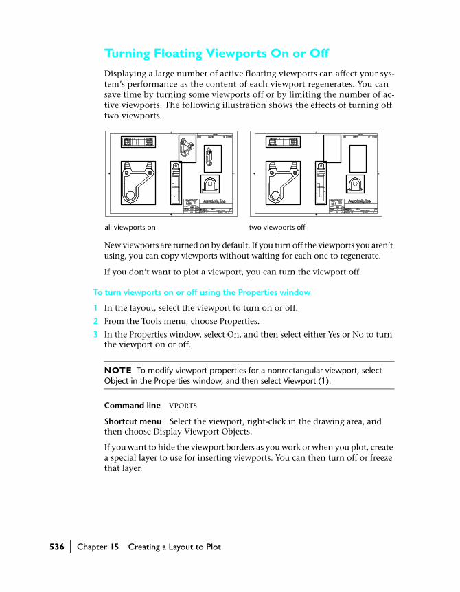
Displaying a large number of active floating viewports can affect your sys-tem’s performance as the content of each viewport regenerates. You can save time by turning some viewports off or by limiting the number of ac-tive viewports. The following illustration shows the effects of turning off two viewports.
New viewports are turned on by default. If you turn off the viewports you aren’t using, you can copy viewports without waiting for each one to regenerate.
If you don’t want to plot a viewport, you can turn the viewport off.
To turn viewports on or off using the Properties window
1 In the layout, select the viewport to turn on or off.
2 From the Tools menu, choose Properties.
3 In the Properties window, select On, and then select either Yes or No to turn the viewport on or off.
NOTE To modify viewport properties for a nonrectangular viewport, select Object in the Properties window, and then select Viewport (1).
Command line VPORTS
Shortcut menu Select the viewport, right-click in the drawing area, and then choose Display Viewport Objects.
If you want to hide the viewport borders as you work or when you plot, create a special layer to use for inserting viewports. You can then turn off or freeze that layer.
all viewports on two viewports off

Attaching Plot Style Tables to Viewports | 537
Attaching Plot Style Tables to Viewports
A plot style is a collection of overrides you can use to change how visible properties of objects are plotted. A plot style table is a collection of plot style definitions that you attach to a layout or a viewport when you want to use plot styles.
Object properties you can override with a plot style include color, line-weight, linetype, line end style, line join and line fill style, and screening. Each new viewport in a layout initially inherits the plot style table (if any) assigned to the layout in which it is placed. You can choose to use the lay-out’s plot style table for the viewport, or you can assign a separate plot style table to the viewport. See chapter 16, “Plotting Your Drawings.”
To visualize the effect of the plot styles attached to your current layout or viewport, select Display Plot Styles in the Page Setup dialog box and then regenerate your drawing, or select Print Preview from the Standard toolbar.
To attach a plot style table to a viewport
1 In the layout, double-click over the viewport where you want to attach a plotstyle table.
2 From the Tools menu, choose Properties.
3 In the Properties window, select Plot Style Table. From the available list, select a plot style table to attach to the current viewport.
Command line PROPERTIES
Editing in Floating Viewports
When you are working in paper space and you want to edit model space geometry, you can return to model space by making a floating viewport current. Changes you make in a floating viewport affect your model and therefore affect all other viewports that display the objects you changed.
You can resize a viewport by manipulating its grips. Scaling the viewport using the SCALE command changes the viewport size without affecting the magnification of the view. To scale a view within a viewport, you can change the zoom magnification or modify the plot scale of the viewport object.

538 | Chapter 15 Creating a Layout to Plot
To edit a drawing in a floating viewport
1 Double-click over the floating viewport that you want to edit to make it current.
Paper on the status bar changes to Model.
2 Edit the drawing.
Scaling Views Relative to Paper Space
Scaling or stretching the floating viewport border does not change the scale of the view within the viewport. Scaling views relative to paper space estab-lishes a consistent scale for each displayed view. To accurately scale the plot-ted drawing, you must scale each view relative to paper space.
When you are working in a paper space layout, the scale factor represents a ratio between the actual size of the model displayed in the viewports and the size of the layout. Usually the layout is plotted at a 1:1 scale. The ratio is de-termined by dividing the paper space units by the model space units. For ex-ample, for a quarter scale drawing, the ratio would be a scale factor of one paper space unit to four model space units, or 1:4. You can change the plot scale of the viewport using the Properties window or the Viewports toolbar.
To modify a viewport scale using the Properties window
1 Select the viewport whose scale you want to modify.
2 From the Tools menu, choose Properties.
3 In the Properties window, select Standard Scale, and then select a new scale from the list.
The scale you select is applied to the viewport.
Command line PROPERTIES
Shortcut menu Select the viewport, right-click in the drawing area, and then choose Properties.
grid and UCS icon on in two viewports
grid on in one viewport, UCS icon on in the other

Editing in Floating Viewports | 539
Scaling AutoCAD Linetypes in Paper Space
You can scale linetypes in paper space using two different methods. You can scale a linetype based on the drawing units of the space in which the object was created, or you can scale a linetype based on the paper space units.
You can set the PSLTSCALE system variable to maintain the same linetype scaling for objects displayed at different zoom factors in a layout and in a floating viewport. For example, set the current linetype to dashed, and then draw a line in a paper space layout. In the layout, create a viewport with a zoom factor of 1x, make that floating viewport active, and then draw a line using the same dashed linetype. The dashed lines should appear the same.
If you set PSLTSCALE to 1 (default) and then change the viewport zoom factor to 2x, the linetype scaling for the dashed line in the layout and the dashed line in the floating viewport will be the same, regardless of the difference in the zoom factor.
To scale pattern linetypes globally in paper space
1 From the Format menu, choose Linetype.
2 In the Linetype Manager, choose Show Details.
3 Under Global Scale Factor, enter a global scale to apply to the linetypes.
4 Choose OK.
Command line LINETYPE
System variables CELTSCALE sets linetype scaling for individual objects.
Related LTSCALE sets the global linetype scale factor.
PSLTSCALE=1, dashes scaled to paper space
PSLTSCALE=0, dashes scaled to space where they were created

540 | Chapter 15 Creating a Layout to Plot
Aligning Views in Floating Viewports
You can arrange the elements of your drawing by aligning the view in one floating viewport with the view in another viewport. For angled, horizontal, and vertical alignments, pan the view in one viewport in relation to a base point specified in another viewport.
To align objects between viewports
1 At the Command prompt, enter mvsetup.
2 Enter a (Align).
3 Choose one of the following alignments:
■ Horizontal: Aligns a point in one viewport horizontally with a base point in another viewport.
■ Vertical: Aligns a point in one viewport vertically with a base point in another viewport.
■ Angled: Aligns a point in one viewport at a specified distance and angle from a base point in another viewport.
1
2
Horizontal alignments
1
2
Vertical alignments

Editing in Floating Viewports | 541
4 Make sure the viewport with the view that is to remain stationary is current. Then specify a base point.
5 Select the viewport with the view you want to realign. Then specify an align-ment point in that view.
6 For angled alignments only, specify a distance and displacement angle from the base point to the alignment point in the second viewport.
Rotating Views in Floating Viewports
You can rotate an entire view within a floating viewport. This feature differs from the ROTATE command, which rotates individual objects.
Notice that only the view rotates, not the viewport borders.
To rotate a view
1 At the Command prompt, enter mvsetup.
2 Enter a (Align).
3 Enter r to rotate the view.
4 Select the viewport with the view you want to rotate.
5 Specify a base point for the rotation.
6 Specify the rotation angle.
The entire view rotates within the viewport.
Angled alignments
original view rotated view

542 | Chapter 15 Creating a Layout to Plot
Creating Nonrectangular Viewports
Using previous AutoCAD releases, you can create rectangular viewports in paper space to display different views of the model. With AutoCAD 2000, you can associate a boundary with a rectangular viewport object and clip the geometry in the viewport to the edge of the boundary. Thus, you can create viewports with irregular or nonrectangular boundaries.
A nonrectangular viewport is created when you associate a clipping object (polyline, circle, region, spline, or ellipse) with a normal viewport object. When you associate these two objects, they remain connected as long as the nonrectangular viewport boundary exists.
To create nonrectangular viewports, you can either create a new viewport with irregular boundaries or alter an existing viewport by redefining its boundary. The new boundary can consist of a closed polyline, circle, spline, ellipse, region, or arc segment.
NOTE If you want to use BHATCH to apply a hatch to a nonrectangular view-port, use the internal point method. If you use the select objects method and try to select the clipped viewport, the underlying rectangular viewport is added to the selection set and is therefore hatched. To apply the hatch inside the view-port boundary, select an internal point.
Creating a New Viewport with Irregular Boundaries
In AutoCAD 2000, the VPORTS command provides the Object and Polygonal options to assist you in defining an irregularly shaped viewport. You can create a new viewport with irregular boundaries by converting an object drawn in paper space into a viewport.
model space geometry defining nonrectangular viewport
nonrectangular viewport

Creating Nonrectangular Viewports | 543
With the Object option, you can select an object to convert into a viewport. A polyline can contain arc or line segments, can be self-intersecting, must contain at least three vertices, and must be closed. The polyline that defines the irregular boundary is associated with the viewport after the viewport is created.
As you define the irregular viewport boundary, AutoCAD calculates the ex-tents of the selected object, then places a viewport object at the corner of the extents of the boundary, and clips the viewport to the object specified in the boundary.
The Polygonal option can be used to create an irregularly shaped viewport by specifying points. The prompt sequence is the same as the prompt sequence for creating a polyline.
Redefining the Boundary of an Existing Viewport
You can redefine the boundary of a viewport by using the VPCLIP command. To clip a viewport, you can use your pointing device to either select an exist-ing object to designate as the new boundary, or specify the points of a new boundary.
To redefine a viewport boundary
1 At the Command prompt, enter vpclip.
2 Select the viewport to clip.
3 Enter d (Delete) to delete the clipping boundary.
4 Enter p (Polygonal).
5 Specify points, or select the object, to define the new viewport boundary.
Shortcut menu Select the viewport to clip, right-click in the drawing area, and then choose Viewport Clip.
model space geometry existing viewport result
new boundary

544 | Chapter 15 Creating a Layout to Plot
Using Grips to Edit Irregular Viewports
When you create an irregularly shaped viewport, AutoCAD calculates the extents of the object selected and places a viewport object at the corner of the extents of the boundary. Depending on the shape of the boundary, the geometry may not be completely displayed in the irregularly shaped view-port. If you want to change the shape of the viewport, you can use grips to edit the vertices of an irregular boundary just as you edit any object with grips.
Freezing the Layer of a Viewport Boundary
If the boundary layer of a nonrectangular viewport is frozen, the boundary is not displayed, and the viewport is not clipped. If the boundary layer is turned off but not frozen, the viewport remains clipped.
Zooming and Panning in a Nonrectangular Viewport
When you zoom or pan inside a nonrectangular viewport, the model space geometry you define is clipped in real time. The geometry outside the bound-ary in the rectangular viewport (underneath the clip boundary) is not visible.
If you use ZOOM Extents on the clipped geometry in an irregularly shaped viewport, AutoCAD zooms to the extents of the clipping boundary, and not all of the geometry in the viewport may be visible.
model space geometry
viewport boundary
viewport after grip editing