Embed Size (px)
Citation preview

Creating a Footprint Map Using AutoCAD from an Aerial Photograph
Tutorial Created by Brijesh Bhatha, 2004. Updated 2006 by Corinne Stewart ([email protected])

GRAPHICS TUTORIAL # B1Creating a Foot Print Map Using AutoCAD from an Aerial Photograph
CP-208 Plan Preparation Studio - Prof. Elizabeth Macdonald 2
In this tutorial we will learn to create a footprint map from an aerial photograph Using AutoCAD STEP – I. Creating A New AutoCAD File: 1. Open AutoCAD. 2. Inthe“FileMenu”select“New”tocreateanewAutoCADfile.3. A dialog box appears, stating “Select a Template”. Select “acad.dwt” and hit “OK”.
File Menu Create New Drawing Dialog box
STEP – II. Setting Up the Drawing Units: 1. In the “Format” menu, select “Units”. 2. A dialog box appears, stating “Create a new Drawing”. Select the appropriate “unit type” from the available options and hit “OK”. n For this tutorial select “Engineering” as the unit type.

GRAPHICS TUTORIAL # B1Creating a Foot Print Map Using AutoCAD from an Aerial Photograph
CP-208 Plan Preparation Studio - Prof. Elizabeth Macdonald 3
STEP – III. Creating Layers: 1. In the “Format” menu select “Layer”, OR enter “Layer” at the Command prompt. 2. A “Layer Properties Manager” dialog box will appear. 3. Select “New” to create a new layer. 4. Typeinalayernamethatidentifiesthelayercontent.
5. Choose a color for the newly created layer by clicking on the color box in the same line as the layer name.
Note: It is advisable to use different colors for different layers as it makes working in AutoCAD easier. One can identify the layers visually. This is also helpful for printing from AutoCAD.
6. Double click on the color box to change the layer color. 7. A “Select Color” dialog box will appear, select a color from the available color options.
Layer Properties Dialog Box
Layer Properties Dialog BoxFormat Menu
Name or rename the created layer
Double-click on the box to change color
Click on the selected layer to make it your current layer

GRAPHICS TUTORIAL # B1Creating a Foot Print Map Using AutoCAD from an Aerial Photograph
CP-208 Plan Preparation Studio - Prof. Elizabeth Macdonald 4
8. Steps 1-7 can be repeated to create different types of layers for different information groups.
• For this tutorial create five layers called “Aerial, Footprint, Parcel, Curb and Reference”. Assign one color to each layer from the first nine “Standard colors”. Select red, yellow, green and cyan for each of these layers respectively.
9. Select a layer with the cursor and click green arrow ( ) again in the “Layer Properties Manager” to create elements or draw in the selected layer. This makes the layer “current” and allows you to draw on it.
The colors with both names and numbers (for now, only use these 9 colors)
The number for the selected color will be seen here
Note: AutoCAD has 256 colors in the main color palette and each color is assigned a number. ThefirstsevencolorsfromtheStandardcolorshave names as well as numbers but all other colorsareidentifiedonlybynumbers.Othercol-ors are available, if color matching is desirable, in the “True Color “and “Color Books” menus. For now, we will focus on the main “Index color” menu.
Creating and Naming new Layers
Selecting with the mouse cursor
Selecting a color by number

GRAPHICS TUTORIAL # B1Creating a Foot Print Map Using AutoCAD from an Aerial Photograph
CP-208 Plan Preparation Studio - Prof. Elizabeth Macdonald 5
Note: Inordertoworkefficientlyitisimportanttounderstandsomebasicconceptsassociatedwithlayers.Tocomfortably work in the layer environment it is also important to know their symbols.
On/Off: Turns layers on and off. When a layer is on, it is visible and available for plotting. When a layer is off, it is invisible and not plotted, even if Plot is on.
Freeze/Thaw: Freezes selected layers in all viewports. You can freeze layers to speed up ZOOM, PAN, and many other operations; improve object selection performance; and reduce regeneration time for complex drawings. AutoCAD does not display, plot, hide, render, or regenerate objects on frozen layers.
Freeze the layers you want to be invisible for long periods. When you thaw a frozen layer, AutoCAD regener-ates and displays the objects on that layer. If you plan to switch between visible and invisible states frequently, use the On/Off setting. You can freeze layers in all viewports, in the current layout viewport, or in new layout viewports as they are created. Lock/Unlock: Locks and unlocks the layers. You cannot edit objects on a locked layer. Locking a layer is use-ful if you want to view information on a layer for reference but do not want to edit objects on that layer.
Note: To use On/Off, Freeze/ Thaw, Lock/ Unlock for layers, select the required layer and click on the icons against the layer as shown in the diagram
On/Off Freeze/Thaw
Lock/Unlock Color
Selected layer The layer is turned off by clicking on the icon
Printing Layer?

GRAPHICS TUTORIAL # B1Creating a Foot Print Map Using AutoCAD from an Aerial Photograph
CP-208 Plan Preparation Studio - Prof. Elizabeth Macdonald 6
STEP – IV. Bringing an Aerial Photo into AutoCAD: 1. Select the “Aerial” layer you have created and make it your current layer. 2. In the “Insert” menu select “Raster Image..”. 3. A “Select Image File” dialog box will appear. 4. Browsetofindtherequiredimagefileandhit“Open”.• Select the image file attached with this tutorial OR the image you created in TUTORIAL # A1. 5. A new dialog box “ Image” will appear on the screen. Hit “OK”.
Note: The “Specify on screen” option for “Insertion point” and “Scale” are turned on by default. It is possible tospecifythescalingfactorinthe“Scale”byundoingthedefaultselection.Howeverusuallyitisdifficulttoknow the actual scale image before inserting it in AutoCAD. Hence it is better scale the image after inserting the image in the drawing •For this tutorial we will scale the image after inserting it in the drawing.6. Provide an insertion point for the image on the screen by clicking the right click of the mouse. 7. “Specify Scale Factor<1>:” appears in the command line, hit enter to retain the existing scale of the image. 8. TheimagenowappearsonthescreenandhasbeeninsertedintoyourAutoCADfile.
Image Dialog Box
The cursor below will ap-pear as shown below, se-lect a point on screen by right-clicking the mouse
GRAPHICS TUTORIAL # B1Creating a Foot Print Map Using AutoCAD from an Aerial Photograph
CP-208 Plan Preparation Studio - Prof. Elizabeth Macdonald 7
STEP - V. Scaling the Aerial Photo: Note: It is advisable to scale the image to real scale i.e. 1:1 before proceeding with drawing the Parcels or footprints. Some scale indication with the image, usually a graphical scale, is helpful to scale it to the real scale. However, when a drawing is lacking scale information, Google Earth can be used to measure distances.
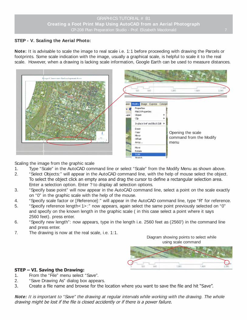
Scaling the image from the graphic scale1. Type “Scale” in the AutoCAD command line or select “Scale” from the Modify Menu as shown above. 2. “Select Objects:” will appear in the AutoCAD command line, with the help of mouse select the object. Toselecttheobjectclickanemptyareaanddragthecursortodefinearectangularselectionarea. Enter a selection option. Enter ? to display all selection options. 3. “Specify base point” will now appear in the AutoCAD command line, select a point on the scale exactly on “0” in the graphic scale with the help of the mouse. 4. “Specify scale factor or [Reference]:” will appear in the AutoCAD command line, type “R” for reference. 5. “Specify reference length<1>:” now appears, again select the same point previously selected on “0” and specify on the known length in the graphic scale ( in this case select a point where it says 2560 feet). press enter.6. “Specify new length”: now appears, type in the length i.e. 2560 feet as (2560’) in the command line and press enter. 7. The drawing is now at the real scale, i.e. 1:1.
STEP – VI. Saving the Drawing: 1. From the “File” menu select “Save”. 2. “Save Drawing As” dialog box appears. 3. Createafilenameandbrowseforthelocationwhereyouwanttosavethefileandhit“Save”.
Note: It is important to “Save” the drawing at regular intervals while working with the drawing. The whole drawingmightbelostifthefileisclosedaccidentlyorifthereisapowerfailure.
Diagram showing points to select while using scale command
Opening the scale command from the Modify menu

GRAPHICS TUTORIAL # B1Creating a Foot Print Map Using AutoCAD from an Aerial Photograph
CP-208 Plan Preparation Studio - Prof. Elizabeth Macdonald 8
Drawing Curb Lines, Parcels, and Building Footprints.
To Draw Curb Lines, Parcels and Building Footprints, we will trace information from the aerial image. The pro-cess of constructing this drawing is conceptually similar to tracing on a drafting table, but here it will be with the help of various AutoCAD commands. Line weights for the various lines are assigned at the time of printing, which means you don’t need to worry about line weights while working on this tutorial. In order to start drawing in AutoCAD one must familiarize with certain basic AutoCAD commands. The follow-ing few commands are the ones which will aid in drawing the necessary plans, however many variations and more complex commands can be used once you are able work in the AutoCAD environment with ease. It is important to use typed commands, as they greatly increase speed. Any command can be repeated by hitting the space bar or return key. Understanding some of the basic AutoCAD Commands:
View Menu Commands:
1. Redraw: Refreshes the display of all viewports. This is helpful to remove marker blips and display artifacts (stray pixels) left by editing commands
2. Regen: REGEN regenerates the entire drawing and recomputes the screen coordinates for all objects in the current viewport. It also re-indexes the drawing database for optimum display and object selection performance. It is generally used in case the drawing is not seen the way it is drawn or it shows display errors.
3. Zoom: Increases or decreases the apparent size of objects in the current viewport. One can change themagnificationofaviewbezoominginandout.Likezoominginaoutwithacamera,zoomdoes notchangetheabsolutesizeoftheobjectsinthedrawing:itchangesonlythemagnificationof the view.
4. Pan: This command moves the viewport to the selected directions without changing the size of the object. This is a helpful tool to navigate through the drawing. Pan is also available by holding down the center mouse button and dragging.
Drawing Menu Commands: 1. Line: This command is used to create straight line segments. You can specify the endpoints of lines us ing two-dimensional coordinates. AutoCAD draws a line segment and continues to prompt for points. You can draw a continuing series of line segments, but each line segment is a separate object. 2. P-line: Created two dimensional polylines. This command is helpful while drawing complex shapes which include lines and curves.
3. Rectangle: Creates a rectangular polyline. This tool is helpful when the objects are orthogonal. For example while drawing city blocks which are rectangular or square in shape. 4. Construction line: Createsaninfiniteline.Thisisaveryimportantcommandasitallowsusto create construction lines in the viewports which become helpful reference for drawing objects on it. Theextendtillinfinity,sotheyarenotconfusedwiththenormaldrawingarea.Itisideal to create a separate, non-printing layer for the construction lines. This allows us turning on and off of these lines at various stages of drawing.

GRAPHICS TUTORIAL # B1Creating a Foot Print Map Using AutoCAD from an Aerial Photograph
CP-208 Plan Preparation Studio - Prof. Elizabeth Macdonald 9
5. Spline:SPLINEfitsasmoothcurvetoasequenceofpointswithinaspecifiedtolerance.
6. Circle: Create a circle with various possible options. For example, by specifying the center and the radius, specifying the center and diameter, by two tangents etc. 7. Arc: Creates an arc using various points. Arcs can also be drawn along with a polyline command.
Edit Menu Commands: 1. Undo: Reverses the most recent action. This command is useful when one wants to revert back to the previousstate.AutoCADhasaninfinitenumberof‘undo’s’,backtowhenthedrawingwasopened. 2. Redo: Reverses the effects of the previous UNDO or U command. This can only be used after the Undo command has been used.
Modify Menu commands: 1. Erase: Removes objects from a drawing. This command is helpful to remove unwanted objects from the drawing. 2. Copy: Thiscommandishelpfultocreateduplicatesofobjectsataspecifieddistancefromtheoriginal. 3. Mirror: Creates a mirror image copy of objects
4. Offset: OFFSETcreatesanewobjectataspecifieddistancefromanexistingobjectorthrougha specifiedpoint
5. Move:Displacesobjectsatspecifieddistanceinaspecifieddirection.
6. Rotate: Youcanrotateobjectsaroundaspecifiedpointwiththehelpofthiscommand. 7. Scale: Enlarges or reduces objects proportionally in the X, Y, and Z directions.
8. Stretch: Moves or stretches objects. AutoCAD stretches arcs, elliptical arcs, lines, polyline segments, 2D solids, rays, traces, and splines that cross the selection window.
9. Trim: Trimsobjectsatacuttingedgedefinedbyotherobjects.Objectsthatcanbetrimmedinclude arcs, circles, elliptical arcs, lines, open 2D and 3D polylines, rays, splines, and xlines
10. Extend:Extendsanobjecttomeetanotherobject.Usesselectedobjectstodefinetheboundary edges to which you want to extend the object. Valid boundary objects include 2D and 3D polylines, arcs, blocks, circles, ellipses, layout viewports, lines, rays, regions, splines, text, and xlines. 11. Fillet: Roundsandfilletstheedgesoftheobjects.FILLETroundstheedgesoftwoarcs,circles, ellipticalarcs,lines,polylines,rays,splines,orxlineswithanarcofaspecifiedradius(thisisgoodfor creating curb radii)
12. UCS: The user coordinate system (UCS) is a movable coordinate system for coordinate entry, planes of operation, and viewing. Establishes a new coordinate system with the XY plane perpendicular to your viewing direction (parallel to your screen). The UCS origin remains unchanged. This is helpful when the objects to be drawn are not parallel or perpendicular to your screen.

GRAPHICS TUTORIAL # B1Creating a Foot Print Map Using AutoCAD from an Aerial Photograph
CP-208 Plan Preparation Studio - Prof. Elizabeth Macdonald 10
After reviewing and understanding the basic commands you will be ready to start drawing in AutoCAD.
STEP - VII. Getting Ready to Draw: 1.Anobjectsnapmodespecifiesasnappointatanexactlocationonanobject.Toactivatevariousobjectsnaps, select “Drafting Settings” in the Tool Menu. Object Snaps can be turned on and off by pressing “F8” on the keyboard.
• Select “Endpoint”, “Midpoint”, “Perpendicular” and “Intersection” from the available options. These snap modes are the basic snap modes, however you can select others when needed.
Note: Ifyouareusingtheattachedimagefileforthistutorialyouwillfindthatthestreetsandbuildingblocksare not parallel to the drawing viewport. This is often the case as aerial photographs are aligned to the real north. We will need to rotate the image to make it parallel to the viewport to simplify drawing in AutoCAD. If youwishthefinaldrawingtohavenorthpointingup,thenyoumustremembertorotatethedrawingbacktoitsoriginalnorthonceyouhavefinished.Tomakethiseasier,createa“North”layer,anddrawseverallinesperpendicular to the blocks before rotating. Freeze this layer before rotation, and use it to realign the image later.
2. Make the “Reference” layer active by selecting it from the “Layer Properties” dialog box as discussed in step III of this tutorial. 3. Drawing construction lines: From the “Draw” Menu select “Construction line” OR type “xline” in the AutoCAD command line. “Specify a point:” now appears in the command line, type‘H’or‘V’forhorizontalorverticalconstruction lines.Forthisexercisetype‘H’andpressenter. “Specify through point: ”now appears in the command line, click on a point on the image at an intersection of a vertical and a horizontal line within the image with the help of the mouse. (As shown in thefigure) A horizontal construction line will appear, press enter construction to complete the command.
Select all the snapping points you want to activate
Select an intersection point as shown
Horizontal Construction Line

GRAPHICS TUTORIAL # B1Creating a Foot Print Map Using AutoCAD from an Aerial Photograph
CP-208 Plan Preparation Studio - Prof. Elizabeth Macdonald 11
4. Rotating the image to make it parallel to the construction line and the viewport. - In the “Modify” menu select “Rotate” OR type “rotate” in the AutoCAD line. - “Select Objects:” appears in the command line, select the image with the help of the mouse. - “Select Objects:” appears in the command line again, press enter if the image is selected. - “Specify base point:” now appears in the command line. Select the corner of the object in the image selected previously for making the construction line. This is also the mid point of the construction line you have already drawn. - “Specify rotation angle or [Reference]:” appear in the command line. Type “R” for reference and press enter. - “Specify rotation angle or [Rotation]:” appear in the command line. Select the same point ( corner of the block and centre of the construction line). - “Specify second point:” will now appear in the command line. Select a point parallel to this point intheimageasshowninthefigure. - “Specify the new angle:” now appears, select any point on the construction line as shown. The image will rotate and the blocks and streets will be parallel and perpendicular to the drawing viewport.
Note: The construction line might not be seen after the image is rotated. Use the command “Display Order” in the “Tools” menu to bring forward or send backwards various objects in relation to each other. Send Image to back so that all drawn objects are visible.
5.Drawparallelandperpendicularconstructionlinesforallcurblinesandparcelsasshowninthefigurebe-low.Thisgridsimplifiesthetaskofdrawingtheblocksandstreets.Drawingparallelandperpendicularcon-struction lines for reference. Take care to note that all blocks are of a consistent size when drawing-this setup will only work when blocks are rectilinear and of the same size.
Select an intersection point as shown
The second point which is parallel to thefirstonehastobeontheimage
Select any point on the construction line
Drawing parallel and perpendicular construction lines for reference
The Rotated Aerial Image

GRAPHICS TUTORIAL # B1Creating a Foot Print Map Using AutoCAD from an Aerial Photograph
CP-208 Plan Preparation Studio - Prof. Elizabeth Macdonald 12
STEP - VIII: Creating Curb lines: To draw curb lines and parcel lines the “rectangle” and “Pline” commands are most useful. The “rectangle” command can be used when the blocks are rectilinear and are parallel to the viewport. The attached image with this tutorial has rectilinear blocks, so we will use rectangle command to create blocks. The method for creating the curb lines and parcel lines are the same. First we will create a curb line. 1. Select the “Curb” layer you have created and make it your current layer. 2. From the “Draw” menu select “Rectangle” OR type “Rectangle” in the AutoCAD command line. 3. “SpecifyfirstCorner:”willappearinthecommandline,specifyanintersectionoftwoconstructionlines on a block by clicking with the mouse. 4. “Specify other corner point or [Dimensions]:” will appear in the command line. Select the diagonally opposite point of the block to the one you selected previously. A rectangle of the size of the block will be drawn. 5. Repeat the steps 1 to 3 for all the blocks to be drawn. If many blocks are similar in all dimensions you can copy those and place them in the new positions.
6. Switch the “Aerial” and “Reference” layer off as discussed in the step III. This will allow you to see the drawn elements clearly. 7. The curb line usually has curved edges. To draw the curves “Fillet” command is useful. 8. In the “Modify” menu click on “Fillet”.
First point to be selected to draw the
rectangle
Second diagonally opposite point to be selected to complete
the rectangle
Construction lines

GRAPHICS TUTORIAL # B1Creating a Foot Print Map Using AutoCAD from an Aerial Photograph
CP-208 Plan Preparation Studio - Prof. Elizabeth Macdonald 13
9. “Current settings: Mode = TRIM, Radius = 0’-0” Selectfirstobjector[Polyline/Radius/Trim]:”willappearintheAutoCADcommandline. 10. Type in “r” in order to specify the radius. 11. “Specifyfilletradius<0’-0”>:”nowappearonthescreen.Specify6’astheradius. 12. “Selectfirstobjector[Polyline/Radius/Trim]:”willappear.Hitenter. 13. Select “Fillet” again. 14. For “Current settings: Mode = TRIM, Radius = 0’-0” Selectfirstobjector[Polyline/Radius/Trim]:“willappear,selectoneedgeoftherectangle. 15. “Selectsecondobject:”willappear,selectthesecondedgeasshowninthefigure.16. The object will have a curved edge as shown in the diagram.
17. Repeat these steps for each corner which has to be curved.
Step - IX. Creating Parcel lines: 1. Select the “Parcel” layer you have created and make it your current layer. 2. The method for creating parcel lines is similar to creating the curb lines. Repeat the steps 1 to 3 from “Creating curb lines” steps.
Second diagonally opposite point to be selected to complete
the rectangle
First point to be selected to draw the rectangle
Corner to Fillet
First line to be selected
First line to be selected
The corner will appear as shown above

GRAPHICS TUTORIAL # B1Creating a Foot Print Map Using AutoCAD from an Aerial Photograph
CP-208 Plan Preparation Studio - Prof. Elizabeth Macdonald 14
STEP X. Drawing Building footprints: Note: Creating building footprints in AutoCAD is conceptually similar to creating parcels in AutoCAD. However the building footprints are usually more complex than just a rectangle, we will need to use a few more com-mands to draw footprints. •For this tutorial you should familiarize yourself with the AutoCAD commands “Pline” and “Arc” as these commands are useful when drawing footprints. A. Drawing an regular and irregular building footprint for buildings without curved forms:
1. Select the “Footprint” layer you have created and make it your current layer. 2. Zoom to the building you want to draw the foot print for by using the “Zoom” command. 3. In the AutoCAD command line, type in “Pline” and press “Enter”. 4. “Specify start point:” now appears in the command line. 5. Select the start point on one corner of the building by pressing the left button of the mouse. 6. “Specify next point or [Arc/Halfwidth/Length/Undo/Width]:” now appears in the command line. 7. Select the next corner of the building. With each selection the command line will ask for the next point. 8. Finish the footprint again on the same point you started and type in “C” for Close when “Specify next point or [Arc/Close/Halfwidth/Length/Undo/Width]:” appears in the command line. This will create a closed polygon which is the footprint of the selected building.
Note: Turning on the “Object Snap” by pressing “F8” will be helpful if the object is orthogonal to the drawing axis. Turn on ORTHO snaps and/or “endpoints” and “perpendicular” line snap settings.
Note: Above is just an example of how to go about selecting consecutive points, however you can start with any point for drawing the building footprint.
Thefirstpointto be selected
The second point to be
selected
The third point to be selected
The last point is the same as thefirstselectedpoint
Continue selecting all the corners of the building till you reach the last point

GRAPHICS TUTORIAL # B1Creating a Foot Print Map Using AutoCAD from an Aerial Photograph
CP-208 Plan Preparation Studio - Prof. Elizabeth Macdonald 15
B. Drawing an regular and irregular building footprint for buildings with curved forms: 1. Follow steps 1-6 from the previous section (A). 2. Select the next corner of the building. With each selection the command line will ask for the next point. 3. After selecting the point from where the curve begins type in “A” for “Arc” in the command line and press “Enter”. 4. ”Specify endpoint of arc or [Angle/Center/CLose/Direction/Halfwidth/Line/Radius/Second pt/Undo/ Width]:” will now appear in the command line. 5. Type in “S” for “Second point” and press “Enter”. 6. “Specify second point on arc:” will now appear in the command line. Specify a second point on the curveasshowninthefigure.Thispointcanbeanywhereonthecurve,buthavingitsomewherenear the midpoint of the curve will help the curve to be more accurate. 7. “Specify end point of arc:” now appears in the command line. Select the end point of the curve as you see it on the screen. 8. ” Specify endpoint of arc or [Angle/CEnter/CLose/Direction/Halfwidth/Line/Radius/Second pt/Undo/ Width]:” will again appear in the command line. To begin drawing a line we have to again change to drawing a line. Enter “L” for “Line” in the command line. 9. “Specify next point or [Arc/Halfwidth/Length/Undo/Width]:” now appears in the command line. Continue drawing the footprint by selecting each corner of the building. 10. Finish the footprint again on the same point you started and type in “C” for Close when “Specify next point or [Arc/Close/Halfwidth/Length/Undo/Width]:” appears in the command line. This will create a closed polygon which is the footprint of the selected building.
Note: Turning on the “Object Snap” by pressing “F8” will be helpful if the object is orthogonal to the drawing axis.
Note: Above is just an example of how to go about selecting points consecutively, however you can start with any point for drawing the building footprint.
Thefirstpointto be selected
The second point to be selected,
the curved surfaces start
from this point
Selecting a second point of the curve
The last point is the same as thefirstselectedpoint
Finishing the curve

GRAPHICS TUTORIAL # B1Creating a Foot Print Map Using AutoCAD from an Aerial Photograph
CP-208 Plan Preparation Studio - Prof. Elizabeth Macdonald 16
• Once you have drawn all the curbs, parcel lines, and building footprints remember to rotate the drawing so that north points in the same direction as on the aerial image.
Thaw the “North” layer that you created at the beginning and select all the graphics except those lines. This can be accomplished by typing SELECT + Enter then typing ALL. Deselect the North Layer lines by holding down the shift key and selecting the lines.
Rotate the image to align with the “North” layer. This can be done by selecting the parcels and rotating until they are perpendicular to the “North” Layer
The footprint map will likely be used as a part of a presentation which may include other graphic images and text. Adobe Illustrator provides greater flexibility in creating and organizing graphics and text compared to AutoCAD. To ready the footprint map for use in Adobe Illustrator, we first need to convert it into PDF file format. This is explained in the TUTORIAL # D2
The drawing showing the parcels and the footprints drawn from the aerial image
Rotate the drawing to align with the north arrow pointing upwards as the aerial image
2. Parcels
1.“North” layer
3. Select Parcels
4. Rotate Parcels until perpendicular with the “North” layer
5.Result