Embed Size (px)
Citation preview

Underground Focus 111
Creating a common language for all who locate buried pipes and cables,
from novice to expert.
How Locating Instruments Work
There are 2 ways to energize the target line1. There are 2 ways to receive the transmitter’s energy2. The transmitter’s energy wants to leave the pipe or cable equally in all directions3. The transmitter’s energy always follows the path of least resistance4. Different transmitter frequencies can and sometimes will do different things5. The line tracing results cannot be changed with the receiver6.
Transmitter: a generator of alternating current, or energy; a miniature power plant.
Receiver: a handheld antenna or series of antennas used to determine the strength and location of a magnetic field.
Transmitter’s energy: electrical power flowing on a pipe or cable away from the transmitter, some of which forms a magnetic field.

Underground Focus 22
Creating a common language for all who locate buried pipes and cables,
from novice to expert.
There Are 2 Ways to Energize the Target Line
1) Metal-to-metal 2) Nonmetal-to-metal
Energize: to transfer the transmitter’s energy to a pipe or cable.
Conductive transmitting antenna:a wire with two ends which connects the transmitter to 1) the pipe or cable and, 2) the earth.
Once the transmitter’s energy is transferred to the pipe or cable, current flows away from the transmitter, reverses, and then flows toward the transmitter. Current that flows in two directions on a line is known as alternating current because the energy which leaves the transmitter will return to the transmitter. This is true whether the pipe or cable was energized by metal-to-metal means or nonmetal-to-metal means. Metal-to-metal is generally referred to as conductive and nonmetal-to-metal referred to as inductive.
1
Conductive: transferring the transmitter’s energy onto a pipe or cable by employing a metal-to-metal connection between the transmitter and the pipe or cable.
Inductive: transferring the transmitter’s energy onto a pipe or cable without employ-ing a metal-to-metal connection between the transmitter and the pipe or cable.
It is important to realize that the conductive transmit-ting antenna uses a single wire, a wire often colored both black and red. Unplugged from the transmitter this wire becomes two wires.
Metal-to-metal: another term for the use of a conductive transmitting antenna.
Nonmetal-to-metal: another term for the use of an inductive transmitting antenna.

3 Underground Focus
Inductive coupler: a type of inductive transmitting antenna that is not located in the transmitter but rather in a clamp that encircles a cable.
When energizing a pipe or cable with a conductive transmitting antenna, the current flows away from the transmitter on the line then returns to the transmitter through the earth, collecting at the grounding device. Alternately, current changes direction and flows away from the transmit-ter through the earth and returns to the transmitter on the line.
An inductive coupler energizes a line through use of an energized coil of wire wrapped around layers of metal. There is no contact between the metallic components of the coupler and the metal of the line being located. The transmitter’s energy exits the coupler onto the line equally in both directions.
Grounding device: a piece of metal driven into earth so that the conductive transmitting antenna may be attached.
... Energizing the Target Line
Hertz: One complete cycle per second.
Current: the flow of electric charge on a pipe or cable as well as through earth.
Each trip out-and-back from the transmitter is known as a half-cycle. Current flows one way on the line in a half-cycle. Current flows both ways on the line in a cycle. A cycle is also known as a hertz.

Underground Focus 4
Inductive transmitting antenna: a coil located in the transmitter whose purpose is to energize the pipe or cable without using a metal-to-metal connection.
In addition to the inductive coupler, a second type of antenna may be used to energize a pipe or cable without employing a metal-to-metal connection. These inductive transmitting antennas are either loops of wire or coils of wire located inside the trans-mitter. The transmitter is placed on the ground with the windings of the loop or coil oriented to the pipe or cable like a tire is oriented to a road.
Pipe or cable
Windings: the wire in a coil which is wrapped around the core.
The windings of the antenna broadcast an electromagnetic field which then energizes the pipe or cable. The transmitted field energizes the line equally in both directions from where the transmitter is placed, just as with the inductive coupler.
... Energizing the Target Line
Loop
Coil
Loop

5 Underground Focus
The electromagnetic field produced by an inductive transmitting antenna is a 3-dimensional field. The antenna is situated in the exact center of the field. When this field energizes the pipe or cable, current begins to flow on the line.
Whether a line was energized by metal-to-metal means or nonmetal-to-metal means, flowing current produces a magnetic field which leaves the line in all directions. The part of the mag-netic field above the ground is detectable by the receiver.
Signal: the part of a magnetic field that intersects a receiving antenna.
Magnetic field: the product of alternat-ing current flowing on a pipe or cable.
... Energizing the Target Line

Underground Focus 6
Concentric signal circles: the magnetic field that orbits the pipe or cable at all distances from the pipe or cable.
The transmitter’s job is now complete: the pipe has been transformed into a transmitting antenna.
Signal circle: the magnetic field that orbits the pipe or cable at a particular distance from the pipe or cable.
Signal strength: measurement of the magnetic field with a tire coil orientation.
... Energizing the Target Line

7 Underground Focus
There Are 2 Ways to Receive the Transmitter’s Energy
Apex: the topmost part of a signal circle.
Coil: wire, usually copper, wrapped around a core in a spool-of-thread type fashion.
Only a coiled receiving antenna can detect magnetic fields produced by alternating cur-rent. A coiled receiving antenna oriented to the pipe or cable like a tire to a road is known as a tire antenna. A tire antenna is capable of quantifying the strength of a signal circle at the point the circle intersects with the coil. When a tire coil is moved perpendicular to the pipe or cable, the strongest signal strength is found at the top of the signal circle, also known as the signal circle’s apex.
2
The second way to detect the magnetic field is enabled when a tire antenna is stood on its side creating a coil orientation resembling a tornado. A tornado antenna does not quantify signal strength but rather indicates whether both sides of the antenna are equally intersected by a signal circle. This equal intersection occurs at the apex of a signal circle.
Coil orientation: the positioning of coil windings within a magnetic field.
Tire
Tornado

Underground Focus 8
1) Peak
2) Null
Tire: a vertical coil winding that pro-vides a peak response; windings that are oriented to the pipe or cable like a “tire to the road.”
Tornado: a horizontal coil winding that provides a null response; windings that are oriented to the pipe or cable like a “tornado traveling down the road.”
Null: a receiver response taken at the apex whereby the coil orientation is horizontal, like a tornado.
Peak: a receiver response taken at the apex whereby the coil orientation is vertical, like a tire to the road.
A receiver response using a tire antenna is known as a peak response. A receiver response using a tornado antenna is known as a null response. Peak quantifies signal strength and null indicates whether both sides of the antenna see equal signal or not.

9 Underground Focus
This single antenna receiver is detecting a peak response and the signal strength is quantified by use of an analog meter.
This multiple antenna receiver is also detecting a peak response using only a single antenna. The signal strength is quantified by use of a numeric digital display.
A peak response can be obtained by using two stacked-peak antennas at the same time. Two concentric signal circles are quantified and the results averaged, resulting in a sharper peak response.
Stacked-peak antennas: two coils—a bottom receiving antenna and a top receiving antenna—which are both situated at the apex of two concentric signal circles.
Antenna
... Receiving the Transmitters Energy
Single antenna receiver
Multiple antenna receiver

Underground Focus 10
Most locating instruments use a “tone/no-tone” audible response when operating in null mode. An audible tone indicates the two sides of the tornado antenna are not intersected equally by a signal circle. Conversely, no audible tone signifies that both sides of the antenna are intersected equally by the same signal circle.
A tornado antenna intersected equally by a signal circle is said to be balanced; not intersected equally, unbal-anced.
Tornado antenna
... Receiving the Transmitters Energy
Balanced response
Response of locating instruments in null mode Balanced
No tone
Needle pegged left
Low digital number, or “0”
Imbalanced
Tone
Needle pegged right
Large numbers

Underground Focus 11
AB
Pipe
The symmetrically-opposed antennas, A and B, are tilted at a 45-degree angle in the bottom of the receiver. As seen here, the position of the pipe will result in A being a tire antenna and B a tornado antenna. If the pipe was on the other side, A would be the tornado antenna and B would be the tire antenna. The user of the receiver finds the direc-tion to the apex by an arrow that points to A or B, whichever antenna is registering a peak response.
A single tornado antenna cannot determine the left-right direction the receiver needs to move to find the apex. Multiple antenna receivers, however, are capable of indicating the direction to the apex. A tire and a tornado antenna working as a team can provide left-right direction to the apex.
... Receiving the Transmitters Energy
Underground Focus 112122
Electronic null: a receiver response whereby two symmetrically and horizontally-positioned peak antennas record identical signal strengths.
Peak
If two horizontally-positioned peak antennas receive the identical peak responses they are balanced. This is known as an electronic null.
If two horizontally-positioned peak antennas receive differing peak responses they are imbalanced.
Multiple antenna receivers can display peak and electronic null responses simultaneously.
Horizontally-positioned peak antenna: on a multiple antenna receiver, a pair of tire coils used to produce an electronic null response
... Receiving the Transmitters Energy
Imbalanced
Balanced
Imbalanced

13 Underground Focus
The Transmitter’s Energy Wants to Leave the Pipe or Cable Equally in All Directions
Round field: a magnetic field that is not an attracting or repelling field.
Not-round field: a magnetic field that is either an attracting or repelling field.
When there are no adjacent metallic objects near an energized pipe or cable, the magnetic field will leave the line equally in all directions. But when adjacent metallic objects are present, the magnetic field does not leave an energized line equally in all directions.
3

Underground Focus 14
Repelling field: a magnetic field whose energy moves away from another field; this field is not circular.
Attracting field: a magnetic field whose energy moves toward another field; this field is not circular.
When the target line is positioned adjacent and paral-lel to a non-target line, the magnetic field leaving the target line is likely to energize the non-target line. This energizing by induction results in two magnetic fields. These fields will either attract one another or repel one another. In either case, the two fields are not round.
Target line: the pipe or cable intended to be detected.
Non-target line: any pipe or cable not intended to be detected.

15 Underground Focus
The Transmitter’s Energy Always Follows the Path of Least Resistance
All of the current that exits the transmitter must return back to the transmitter. The route that the exiting current takes as it travels away from the transmitter is determined by the route it will take back to the transmitter. The complete route, or circuit, is determined by the path of least resistance.
Wherever the metal pipe or cable comes into contact with earth is a location where some—if not all—of the current stops traveling away from the transmitter and begins traveling back to the transmitter.
4
Path of least resistance: the route which current takes both away from the transmitter and back to the transmitter.

16Underground Focus
Different Transmitter Frequencies Can and Sometimes Will Do Different Things
A change of transmitter frequency may change the path of least resistance. Therefore a change of transmitter frequency may change the route the transmitter’s energy travels.
5
AM radio’s lowest frequency is 530,000 hertz, or 530 kilohertz. FM radio utilizes higher frequencies, frequencies measured in megahertz.
Frequency: the transmitter’s energy as measured in hertz or kilohertz.
Kilohertz: 1000 hertz.
Locating instrument transmitter frequencies are divided into two groups: low, or audio frequencies and high, or radio frequencies.
What makes one transmitting frequency different from another is the level of induced current. High frequencies have more induced current than low frequencies. Transmitter frequencies can range from 128 hertz to 480,000 hertz.

17 Underground Focus
The Line Tracing Results Cannot be Changed With the Receiver
The receiver is the “dumb end” of the locating instrument. It is only capable of analyzing a few things: assessing the level of current on the line and determining the strength and shape of the mag-netic field leaving the line.
6
If it is determined that the cur-rent on the line to be traced is not sufficient to build a field, or that the field is not round enough to provide an accurate location atop the ground, then these results can only be changed by doing some-thing different with the transmit-ter. This is why the transmitter is known as the “smart end.”

Underground Focus 18
Why Locating Instruments Work: Current
The Current That Leaves the Transmitter Must Come Back to the Transmitter
What enables these street lights to illuminate the night? The answer is current. Without current, the lights go dark.
Current is generated when voltage at the power plant is applied to both metal and earth; metal being the electric cables that run from the power plant and earth being soil. Current will flow as long as the electric line is metallically continuous and the end of the line is connected, or grounded to earth.
Current which leaves the power plant must come back to the power plant. The two metallic components of this pri-mary cable, the conductor and the neutral, will always be carrying current in opposite directions from one another. While one metal component carries current away from the power plant the other metal component carries current traveling back to the power plant.
Transmitters are the heart of pipe and cable locating instruments. Transmitters are miniature power plants which energize the pipe or cable just like a power plant energizes electric cables: applying voltage to both metal and earth in order to produce current on the line.
This is a street light cable. Flowing current on these wires builds a magnetic field that wants to leave these wires equally in all directions. Pull these red conductor wires apart and electrical current will not flow to the lights. When there is no current flow, no magnetic field is produced.

19 Underground Focus
There Are 4 Major Factors That Influence Current Flow on a Line
Far-end grounds Insulation
FrequencyEarth
Far-end: the end of a line leg opposite of the transmitter location.
Is a line leg connected to earth at the far-end or not?
Is the line leg insulated from earth or not?
What is the soil type and what is the moisture content of that soil?
What transmitter frequency is being used? Higher frequencies have more induced current than lower frequencies.
Line leg: a single-direction section of a pipe or cable which has metallic continuity.

Underground Focus 20
The Receiver Assesses the Current Level at Any Point Along the Line
OK current
Poor current
Good current
When the receiver is held motionless atop the peak response, the tire antenna or antennas become capable of assessing the current level on the pipe or cable at that particular location.
Good current is characterized by a still or steady peak response.
The current level on the pipe or cable is termed OK current when the peak response is not entirely steady but rather fluctuates or flutters within a limited range.
Constant and wide-ranging peak response fluctuation is known as poor current. A poor current assessment mandates a change in the deployment of the transmitter.
Good current or OK current levels are sufficient levels with which to continue tracing of the pipe or cable.

How to Use Locating Instruments: The Receiver
There Are 5 Ways to Determine the Shape of the Magnetic Field After it Leaves the Pipe or Cable
Peak versus null1. Digital depth validation2. Triangulation3. Peak method4. Null method5.
21 Underground Focus
The magnetic field or signal, leaves the pipe or cable in either a circular shape or non-circular shape.
Although the signal wants to leave the pipe or cable equally in all directions, the presence of other nearby metallic objects may change that outcome. Other metallic objects energized by the transmitter will work to distort the circular shape of the magnetic field leaving the target utility.
There are two signal field shapes: round and not-round. In general, a round field equates to accurate locate results and a not-round field equates to inaccurate locate results. But this statement is an oversimplification. To extract the maximum amount of information from the receiver regarding field shape, there are five methods of receiver utilization.
Do the peak and null responses agree at the same location on the ground? If yes, the signal is round. If no, the signal is not round.
Not-round field: a magnetic field that is either an attracting or repelling field.
1) Peak versus null
Round field: a magnetic field that is not an attracting or repelling field.
Peak Null
Underground Focus 22
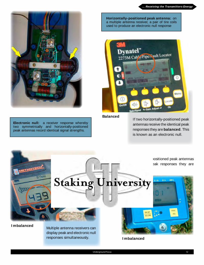
2) Digital depth validation
Obtain a digital depth mea-surement and then lift the receiver a known distance. Is the difference between the second depth reading and the first depth reading equal to the distance the receiver was lifted? If yes, the field is round. If no, the field is not round.
If the receiver was lifted 8” then this field is round.
If the receiver was lifted 8” then this field is not round.
Digital depth: a pipe or cable depth estimation utilizing at least two stacked-peak antennas situ-ated a fixed distance apart.
Lifting the receiver results in a lower peak reading.

23 Underground Focus
3) Triangulation
Next, the receiver is pulled away from the target line in perpendicular fashion until another balanced reading is obtained. A measurement is taken between the two balanced readings. The process is repeated on the opposite side of the line and the two measurements compared. If the two measurements are equal, the field is round. If not, the field is not round.
A balanced null reading is the result of a signal circle intersecting the antenna or antennas in an equal or symmetric manner.
After obtaining a balanced reading in the null mode over the line, the receiving antenna or antennas are positioned to form a 45-degree angle with the level ground. The receiver is now indicating an imbalanced reading.
Imbalanced reading
Balanced reading
... Determining Magnetic Field Shape

Underground Focus 24
4) Peak method
5) Null method
Next, the receiver is pulled away from the line along the ground in the opposite direction until the same peak reading is detected. A measurement to the original peak reading is made and compared to the measurement taken on the other side of the line. If the two measurements are equal, the field is round. If not, the field is not round.
In the null mode and at a balanced reading over the line, the instrument is lifted straight up. If there still exists a balanced reading, the field is round. If the receiver has to be moved perpendicularly from the line to achieve a balanced reading, the field is not round.
Finding the line in peak mode, the receiver is pulled a random distance away from the line in a perpendicular manner and placed on the ground. The peak reading is noted and the distance away from the original peak is measured.
... Determining Magnetic Field Shape

25 Underground Focus
Change the grounding system1. Change from conductive to inductive (or vice versa)2. Move the transmitter3. Change the frequency4.
1) Change the grounding system
Any attempt to increase the current level on a target line must be done at the transmitter. Any attempt to change a target line’s field shape from not-round to round must be done at the transmitter, too. There are only four things that can be changed at the transmitter:
Change the grounding system to increase the current level on the line by:
A. Increasing the length of the conductive transmitting antenna creates a larger conductive transmitting antenna, likely increasing the current level on a line.
B. Ground to a metallic object that has a lot of surface contact with earth, such as the fence in the background. A grounding device that has more surface area with earth becomes a larger transmitting antenna.
C. Connect to a grounding device that reaches deeper into earth. Earth may be dry at shallow levels but wetter at deeper levels. As soil moisture increases so does the size of the transmitting antenna.
A B
C
How to Use Locating Instruments: The Transmitter
There Are 4 Ways to Change Tracing Results with the Transmitter

26Underground Focus
Close-end: the end of a line leg where the transmitter is located.
Change the location of the grounding device to attempt to change a not-round field to a round field. Grounding over or near a non-target line may energize the non-target line thus creating fields that are not-round. Move the grounding device away from the location of non-target lines in order to influence field shape.
Every line has two ends so grounding system changes can be made at the far-end, too. These far-end grounding changes include un-bonding, which keeps the current from easily flowing onto other line legs.
Changing the grounding system at the far end.Un-bond: the physical detachment of one line leg from other line legs or a ground.
Caution: Un-bonding is a practice limited to communication cables, tracer and test wires, and other nonelectrical conductors.

27 Underground Focus
Close-end ground: metal making contact with earth at the end of a line leg where the transmitter is deployed.
Using a metal-to-metal antenna at a close-end ground location creates a path for current to quickly return to the transmitter. This leaves less energy to energize the target line.
If an insulated target line can be un-bonded from its close-end ground then there will be no energy lost to earth, increasing current levels on the target line.
Adding a jumper creates a far-end ground when there was not one beforehand.
Caution: Un-bonding is a practice limited to communication cables, tracer and test wires, and other nonelectrical conductors.
Far-end ground: a pipe or cable’s metal component making contact with earth at the far-end.
... Changing the Results with the Transmitter

28Underground Focus
2) Change from conductive to inductive (or vice versa)
In most instances there can be no more than two locations per line leg to utilize a conductive transmitting antenna. But an inductive antenna can be deployed anywhere along a line leg. Changing from conductive to inductive may increase the current on the line or change the target line’s field shape. The same is true if changing from inductive to conductive. A change of transmitter deployment changes the path of least resistance, which in turn can change line tracing results.
No matter whether a transmitter is used conductively or inductively, the resulting current flows in opposite directions each successive half-cycle. But what can make conductive and inductive results radically different from each other is the location along the line leg where the transmitter is deployed.
When changing from one method of energizing the line to the other, close-end and far-end grounding of the target line, as well as the number of line legs that are grounded to each other, determine whether conductive or inductive results will be superior.
... Changing the Results with the Transmitter

29 Underground Focus
3) Move the transmitter
Moving the transmitter from one conductive or inductive location to another location changes the path of least resistance. A change in the path of least resistance may change line tracing results, either resulting in a higher current level or a more round field shape.
... Changing the Results with the Transmitter

30Underground Focus
Different transmitter frequencies can and sometimes will do different things. That’s because what makes one frequency different from other frequencies is the amount of induced current. A change in induced current can change line tracing results.
4) Change the frequency
Signal split: a location along the pipe or cable where the transmitter’s energy can begin to travel on two or more new line legs.
In general, lower frequencies travel greater distances on insulated, continu-ously metallic and far-end grounded target lines. But if the target line is not grounded at the far-end, if the line is not contin-uously metallic, or if the line has signal splits, high frequencies can travel greater distances than low frequencies on the line leg that is to be traced.
If a target line is energized conductively at a close-end ground location, a lot of the current instantly returns to the grounding device and does not travel on the line. This is particularly troublesome when using the lowest transmitter frequencies. Changing to a higher frequency can solve this problem because the increased amount of induced current allows the transmitter’s energy to travel in multiple directions, which now includes the target line.
... Receiving The Transmitters Energy... Changing the Results with the Transmitter

31 Underground Focus
Using locating instruments boils down to two things: 1) assessing the current level along the target line and 2) assessing the target line’s magnetic field shape. But good current levels and round fields do not guarantee that the line being traced is the target line. The locating instrument is not capable of identifying the line; only the user of the locating instrument can confirm that the line being traced is the target line. This determination is made by following the trace to logical and visual endpoints.
Current
Endpoint
Shape
Locating is About Current, Shape and Endpoints

32Underground Focus