Embed Size (px)
Citation preview

INSTALL-MHS/SM: 99903053: PARTS-1
Crane Installation ManualModel 4/29Model 5/35Model 6/45
IOWA MOLD TOOLING CO., INC.BOX 189, GARNER, IA 50438-0189
641-923-3711TECHNICAL SUPPORT FAX: 641-923-2424
MANUAL PART NUMBER: 99903053
20111129
Iowa Mold Tooling Co., Inc. is an Oshkosh Corporation Company.
INSTALL-MHS/SM: 99903053: PARTS-2
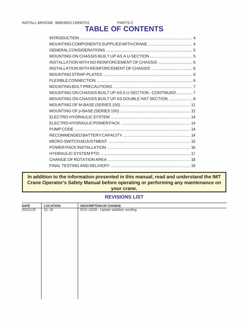
TABLE OF CONTENTSINTRODUCTION ................................................................................................... 4
MOUNTING COMPONENTS SUPPLIED WITH CRANE ....................................... 4
GENERAL CONSIDERATIONS ............................................................................ 5
MOUNTING ON CHASSIS BUILT UP AS A U-SECTION ..................................... 5
INSTALLATION WITH NO REINFORCEMENT OF CHASSIS .............................. 5
INSTALLATION WITH REINFORCEMENT OF CHASSIS .................................... 6
MOUNTING STRAP-PLATES ............................................................................... 6
FLEXIBLE CONNECTION .................................................................................... 6
MOUNTING BOLT PRECAUTIONS ...................................................................... 7
MOUNTING ON CHASSIS BUILT UP AS A U-SECTION - CONTINUED .............. 7
MOUNTING ON CHASSIS BUILT UP AS DOUBLE HAT SECTION ..................... 8
MOUNTING OF M-BASE (SERIES 150) ............................................................. 11
MOUNTING OF p-BASE (SERIES 150) .............................................................. 12
ELECTRO-HYDRAULIC SYSTEM ...................................................................... 14
ELECTRO-HYDRAULIC POWER PACK ............................................................. 14
PUMP CODE ...................................................................................................... 14
RECOMMENDED BATTERY CAPACITY ........................................................... 14
MICRO-SWITCH ADJUSTMENT ........................................................................ 15
POWER PACK INSTALLATION ......................................................................... 16
HYDRAULIC SYSTEM PTO ............................................................................... 17
CHANGE OF ROTATION AREA ......................................................................... 18
FINAL TESTING AND DELIVERY ...................................................................... 19
19990701
In addition to the information presented in this manual, read and understand the IMTCrane Operator's Safety Manual before operating or performing any maintenance on
your crane.
REVISIONS LIST
DATE LOCATION DESCRIPTION OF CHANGE20111129 10, 18 ECN 11628 - Update stabilizer wording

INSTALL-MHS/SM: 99903053: PARTS-3INTRODUCTIONA truck chassis and hydraulically operated crane(loader) are advanced technical products. When theseproducts are combined into one efficient tool, it isimportant that the installation of the crane on thechassis, reinforcement of the chassis, and choice ofpump and hydraulic connections be performed in aprofessional and correct manner.
Installation of the crane (loader), and reinforcement ofthe chassis, must be performed in accordance withthe instructions of the carrier vehicle manufacturerand the information provided in this InstallationManual.
WARNINGFAILURE TO ADHERE TO THE INSTRUCTIONSPROVIDED BY THE VEHICLE AND CRANEMANUFACTURER CAN RESULT IN EQUIPMENTFAILURE, SERIOUS INJURY, OR DEATH.
WARNINGREAD AND UNDERSTAND THE IMT CRANEOPERATORS SAFETY MANUAL AND ALL OTHERAPPLICABLE INSTRUCTION MANUALS WHICHACCOMPANIED YOUR CRANE. FAILURE TO DO SOMANY RESULT IN EQUIPMENT FAILURE, SERIOUSINJURY, OR DEATH.
MOUNTING COMPONENTS SUPPLIED WITH CRANE
DESCRIPTION QTY PART NO.LOCK NUT M20 4 30 894BOLT M20X290 4 66 038MOUNTING CLAMP 2 12 82 273MOUNTING BRACKET 2 12 82 303LOCK NUT M20 4 30 894COMPLETE KIT REF 12 80 520
DESCRIPTION QTY PART NO.BOLT M20X200 4 66 027MOUNTING CLAMP 2 12 31 453MOUNTING BRACKET 2 12 31 443LOCK NUT M20 4 30 894COMPLETE KIT REF 12 30 040
DESCRIPTION QTY PART NO.LOCK NUT M16 4 30 892WASHER 4 12 26 264BOLT M16X250 4 66 023MOUNTING CLAMP 1 12 26 234MOUNTING CLAMP 1 12 26 384MOUNTING BRACKET 2 12 11 784WASHER 4 12 26 264LOCK NUT M16 4 30 892COMPLETE KIT REF 12 29 110
DESCRIPTION QTY PART NO.LOCK NUT M16 4 30 892WASHER 4 12 26 264BOLT M16X250 4 66 023MOUNTING CLAMP 2 12 11 324MOUNTING BRACKET 2 12 11 784WASHER 4 12 26 264LOCK NUT M16 4 30 892COMPLETE KIT REF 12 10 160
Series150
Series 200
Series 250
Series 260
19990701

INSTALL-MHS/SM: 99903053: PARTS-4
In order to prevent the accumulation of rainwater ontop of the base, the upper part of the base must belocated either above or level with the deck. Seedrawing below.
GENERAL CONSIDERATIONSNormally the crane is mounted below the deck, which hasbeen cut out to accomodate the base. See drawing below.
MOUNTING ON CHASSIS BUILT UP ASA U-SECTIONWhen installing the crane to a wide chassis frame,theleft mounting bracket may, on some models, interferewith a 0.2" (5mm) reinforcement plate which has beenwelded under the cross members. To prevent thecrane from leaning to one side, the right mountingbracket is to be mounted 0.2" (5mm) higher than theleft. See drawing below.
INSTALLATION WITH NOREINFORCEMENT OF CHASSISTightening of bolts must be done in stages in order toensure that the clamp applies pressure evenlyagainst the cross members. See drawing below.
Number of M12 bolts in mounting bracketLOADER SIDE OPPOSITE SIDE
1.0-1.5tm 2x3 stk. 2x2 stk1.5-2.6 tm 2x4 stk. 2x3 stk.
19990701

INSTALL-MHS/SM: 99903053: PARTS-5INSTALLATION WITHREINFORCEMENT OF CHASSISThe drawing below shows mounting of subframefastened to the chassis by means of strap plates infront and flexible fasteners at the rear. The subframeis made of U-sections. Another, slightly lower 0.16"(4mm) U-section is welded across the frame andbetween the frame members and in-line with the frontmounting bolts. Aft, the U-sections are placed at adistance of 78.75" (2m) maximum.
MOUNTING STRAP-PLATES FLEXIBLE CONNECTION
19990701
From the rear mounting bolt towards the rear, thesubframe is fastened by means of strap-plates at adistance of approximately 31.5" (0.8m), then bymeans of flexible fasteners at a distance of 47.25"(1.2m) maximum to the rear. See drawing.
If the distance from the front mounting bolt to thefront edge of the subframe is more than 7.9"(200mm), a strap-plate should be mounted.

INSTALL-MHS/SM: 99903053: PARTS-6MOUNTING BOLT PRECAUTIONSNote that the mounting bolts are made of heat-treatedsteel of high quality, and that under no circumstancesshould they be bent or heated. The threads havebeen rolled and must not be lengthened by means ofcutting. Doing so will weaken the bolts.
Nuts must never be secured by tack welding.
The mounting fittings are bolted onto the chassisframe by means of driven bolt connections. It is veryimportant that special bolts are used, on which thesmooth part of the bolt shaft is able to reach almostthrough the mounting bracket and the chassis.
Drilling diameter for a .12mm bolt is 11.8mm (.465").
A hard washer (HB 200) must be placed under thehead of the bolt and nut.
MOUNTING ON CHASSIS BUILT UP ASA U-SECTION - CONTINUED
On very wide chassis frames, it may be necessary toplace the mounting clamps (or one part of it) on theinside of the chassis frame.
If the rotation system is blocking the mounting clamp,the mounting clamp must be split and welded to thebase. See drawing below.
19990701

INSTALL-MHS/SM: 99903053: PARTS-7MOUNTING ON CHASSIS BUILT UP ASDOUBLE HAT SECTIONProposal A
DESCRIPTION DIMENSION PART NO.Distance pipe Du =20mm (.8") 12 13 824
Di =12.5mm (.5")L =140mm (5.5")
Steel bolt M12x150 (5.9") 30 195M12x130 (5.1") 30 198
Lock nut M12 30 890Facet washer Ø24/Ø13x2.5 31 131
19990701

INSTALL-MHS/SM: 99903053: PARTS-8
Proposal B
If the chassis requires reinforcement, the followingmethod of installation may be employed.
The base of the crane must rest directly on both,mounting bracket and U-section. The U-section maybe clasped across the subframe and then weldedonto the frame.
The U-section may be made of 2 angular sectionswelded together, as shown below.
NOTESee information in Proposal A for information ondistance tube, bolt, lock nut and washer.
19990701

INSTALL-MHS/SM: 99903053: PARTS-9Proposal C To avoid deformation of the chassis, the length of
tube 1 and 2 should be adjusted in such a mannerthat the distance (a) is approximately 0.04" (1mm)when the fittings have been loosely placed around thechassis. See drawing below.
The U-section may be made of 2 angular sectionswelded together, as shown below.
19990701

INSTALL-MHS/SM: 99903053: PARTS-10MOUNTING OF M-BASE (SERIES 150)The drawing below shows two alternatives (A & B)which may be used depending on chassis spaceavailable.
DESCRIPTION PART NO.STABILIZER SET, INCL.FRAME 12 12 430STABILIZER SET, EXCL. FRAME 12 12 420
CAUTIONDO NOT WELD ON THE CHASSIS FRAME.
20111129

INSTALL-MHS/SM: 99903053: PARTS-11MOUNTING OF P-BASE (SERIES 150)The P-base has been designed in such a manner thatit does not have to be connected to the chassisframe. It is bolted directly to the deck.
CAUTIONIF THE VEHICLE HAS A WOODEN DECK OR IF THESECTIONAL PLATFORM IS TOO SOFT, IT SHOULDBE REINFORCED UNDER THE CRANE MAST ASSHOWN ON THE FOLLOWING PAGE.
19990701

INSTALL-MHS/SM: 99903053: PARTS-12CAUTION
THE FRONT OF THE PLATFORM SHOULD BEFASTENED TO THE CHASSIS SECURELYENOUGH THAT THE CRANE CANNOT LIFT THEPLATFORM FROM THE CHASSIS.
19990701

INSTALL-MHS/SM: 99903053: PARTS-13ELECTRO-HYDRAULIC SYSTEM
ELECTRO-HYDRAULIC POWER PACKElectric connections are protected against corrosionusing Tectyl 894, or equivalent.
Power consumption Recommended battery capacity
SERIES 12V 24V 12V 24VSeries 150 115 amp 55 amp 83 amp-hr 60 amp-hrSeries 200 155 amp 80 amp 120 amp-hr 60 amp-hrSeries 250 280 amp 140 amp 143 amp-hr 84 amp-hrSeries 260 280 amp 140 amp 143 amp-hr 84 amp-hr
19990701
PUMP CODE
SERIES 150 AND 200
CODE - stamped on pump housing: - - V - - - D - - - - - -
VOLTAGE
12 volt24 volt
PUMP CAPACITY
050 = 0.483 S.150130 = 0.973 S.200
MONTH
YEAR
SEIAL NUMBER
RECOMMENDED BATTERY CAPACITY

INSTALL-MHS/SM: 99903053: PARTS-14MICRO-SWITCH ADJUSTMENTThe micro-switch must be adjusted in such a mannerthat the motor starts at 0.31" - 0.39" (8-10mm) oflever travel. The switch is cut off when the spoolpresses on the roller.
Method of adjustment:
1. Unfasten the screw (a) and place the micro-switchin such a manner that the roller is placed preciselyunder the top of the spool.
2. The travel of the lever 0.31" - 0.39" (8-10mm) isadjusted by unfastening the screw (b or c) andremoving the spool or the micro-switch.
19990701

INSTALL-MHS/SM: 99903053: PARTS-15POWER PACK INSTALLATIONThe electro-hydraulic power pack is normally placedbehind the driver's seat in the cab, but may also beplaced between the side members. If it is placedbetween the side members, the power pack should beprotected using a protection plate.
NOTEALWAYS REFILL THE TANK AFTER BLEEDING OFTHE CYLINDERS.
When employing a separate power pack, the base ofthe crane must be filled with oil in order to protect therotation system against corrosion.
OIL CAPACITYSeries 150: 0.79 gallons (3 liters)
Series 200: 2.11 gallons (8 liters)
19990701

INSTALL-MHS/SM: 99903053: PARTS-16HYDRAULIC SYSTEM PTO
The electric system is connected as shown in thedrawing below (or see hydraulic diagram in theInstruction Manual).
Choose type of oil according to the table in theInstruction Manual, and fill tank with oil to the levelstated on the level-glass or oil pin.
NOTEALWAYS REFILL THE OIL TANK AFTER HAVINGBLED THE CYLINDERS.
NOTEIN GENERAL, THE EXTERNAL PUMP IS NOTSUPPLIED WITH THE CRANE, BUT CAN BEORDERED SEPARATELY.
19990701

INSTALL-MHS/SM: 99903053: PARTS-17CHANGE OF ROTATION AREA 1. Position the crane so that the rotation to bothsides is exactly the same (neutral position).
2. Empty the base of oil through the drain plug (5).
3. If the crane has two rotation cylinders (1), one isremoved. If the crane has four rotation cylinders (1),two are removed.
4. Pull out the slide block (4) by the threaded hole(M8).
5. Pull out the rack (3).
6. Manually turn the crane mast to the required "C"position ("C" indicates the middle of the rotation area- see Fig II).
7. Place the rack (3) in the rotation housing so thatthe distance shown in Figure II is observed,depending on the mutual mesh of the teeth.
8. Place the slide block (4) behind the rack (3) andremount the rotation cylinder (1)
9. The bolts (2) are lubricated using Loctite Normalor Loctite No. 242, and then remounted.
10. The drain plug (5) is remounted and the baserefilled with oil at the air filter (6).
19990701

INSTALL-MHS/SM: 99903053: PARTS-18FINAL TESTING AND DELIVERYWhen the crane has been mounted, the followingshould be done:
1. Fill the base of the crane with the specifiedamount of oil and lubricate the crane.
2. All functions of the crane should be bled.
3. Check the pressure setting with a pressure gauge.
4. Check that all adjustment screws are sealed.
5. Check, and if necessary, tighten all connections.
6. Check that all hydraulic hoses are free of twists,not stuck and are of the proper length to permit freemovement throughout the range of the crane.
7. Load and function test. Check that the micro-switches are correctly adjusted (see Micro-switchinformation previously discussed).
8. Top up the hydraulic oil.
When the crane is delivered, the following should bedemonstrated:
1. Use of stabilizer leg.
2. Operation of the loader.
3. Maintenance procedures.
An explanation of the above points can be found inthe Instruction Manual for each specific crane.
20111129

INSTALL-MHS/SM: 99903053: PARTS-1919990701

INSTALL-MHS/SM: 99903053: PARTS-20
IOWA MOLD TOOLING CO., INC.BOX 189, GARNER, IA 50438-0189
641-923-3711TECHNICAL SUPPORT FAX: 641-923-2424
MANUAL PART NUMBER: 99903053
20000707