Embed Size (px)
DESCRIPTION
Garden Tractor manual
Citation preview

L NUMBER 917.257720 OWNER'SMANUAL
AssemblyOperationCustomer ResponsibilitiesService and AdjustmentsRepair Parts
CAUTION: Read and follow all safety rules and instructions before operating this equipment,
Downloaded from www.Manualslib.com manuals search engine

SAFETY RULESSafe Operation Practices for Ride-On Mowers
IMPORTANT: THIS CUTTING MACHINE IS CAPABLE OFAMPUTATING HANDSAND FEETAND THROWING OBJECTS.FAILURE TO OBSERVE THE FOLLOWING SAFETY INSTRUCTIONS COULD RESULT IN SERIOUS INJURY OR DEATH.
L GENERAL OPERATION
* Read, understand, and follow all instructions in the manualand on the machine before starting.
Only allow responsible adults, who are familiar with theinstructions, to operate the machine.
Clear the area of objects such as rocks, toys, wire, etc.,which could be picked up and thrown by the blade.
* Be sure the area is clear of other people before mowing. Stopmachine if anyone enters the area.
, Never carry passengers.
- Do not mow in reverse unless absolutely necessary. Alwayslook down and behind before and while backing.
Be aware of the mower discharge direction and do not pointit at anyone. Do not operate the mower without either theentire grass catcher or the guard in place.Slow down before turning.
= Never leave a running machine unattended. Always turn offblades, set parking brake, stop engine, and remove keysbefore dismounting.
® Turn off blades when not mowing.
® Stop engine before removing grass catcher or uncloggingchute.
o Mow only in daylight or good artificial light.o Do not operate the machine while under the influence of
alcohol or drugs.
- Watch for traffic when operating near or crossing roadways.
- Use extra care when loading or unloading the machine intoa trailer or truck.
IL SLOPE OPERATION
Slopes are a major factor related to loss-of-control and tipoveraccidents, which can result in severe injury or death. All slopesrequire extra caution. If you cannot back up the slope or ifyou feeluneasy on it, do not mow it.
DO:o Mow up and down slopes, not across.* Remove obstacles such as rocks, tree limbs, etc.
® Watch for holes, ruts, or bumps. Uneven terrain couldoverturn the machine. Tafl grass can hide obstacles.
® Use slow speed. Choose a low gear so that you will not haveto stop or shift while on the slope.Follow the manufacturer's recommendations for wheelweights or counterweights to improve stability.
Use extra care with grass catchers or other attachments.These can change the stability of the machine.
Keep all movement on the slopes slowand gradual Do notmake sudden changes in speed or direction.
o Avoid starting or stopping on a slope. If tires lose traction,disengage the blades and proceed slowly straight down theslope.
DO NOT:
Do not turn onslopes unless necessary, and then, turn slowlyand gradually downhill, if possible.Do not mow near drop-offs, ditches, or embankments. Themower could suddenly turn over if a wheel is over the edgeof a cliff or ditch, or if an edge caves in.
, Do not mow on wet grass. Reduced traction could causesliding.
. Donottrytostabilizethemachinebyputtingyourfootontheground.
, Do not use grass catcher on steep slopes.
t11. CHILDREN
Tragic accidents can occur if the operator is not alert to thepresence of children. Children are often attracted to the machineand the mowing activity. Neverassume that children will remainwhere you last saw them.
* Keep children out ofthe mowing area and under the watchfulcare of another responsible adult.
* Be alert and turn machine off if children enter the area.
, Before and when backing, look behind and down for smallchildren.
, Never carry children. They may fall off and be seriouslyinjured or interfere with safe machine operation.
- Never allow children to operate the machine.
* Use extra care when approaching blind corners, shrubs,trees, or other objects that may obscure vision.
IV. SERVICE
- Use extra care in handling gasoline and other fuels. They areflammable and vapors are explosive.
Use only an approved container.
Never remove gas cap or add fuel with the enginerunning. Allow engine to cool before refueling. Do notsmoke.Never refuel the machine indoors.
Never store the machine or fuel container inside wherethere is an open flame, such as a water heater.
• Never run a machine inside a closed area.
Keep nuts and bolts, especially blade attachment bolts, tightand keep equipment in good condition.
Never tamper with safety devices. Check their properoperation regularly.
, Keep machine free of grass, leaves, or other debris build-up.Clean oil or fuel spillage. Allow machine to cool beforestoring.
• Stop and inspect the equipment if you strike an object.Repair, if necessary, before restarting.
, Never make adjustments or repairs with the engine running.
, Grass catcher components are subject to wear, damage, anddeterioration, which could expose moving parts or allowobjects to be thrown. Frequently check components andreplace with manufacturer's recommended parts, when nec oessary.Mower blades are sharp and can cut. Wrap the blade(s) orwear gloves, and use extra caution when servicing them.
- Check brake operation frequently. Adjust and service asrequired.
Look for this symbol to point out impor-tant safety precautions. It meansCAUTION!!! BECOME ALERT!!! YOURSAFETY IS INVOLVED.
CAUTION: Always disconnect sparkplug wire and place wire where it cannotcontact spark plug in order to preventaccidental starting when setting up,transporting, adjusting or makingrepairs,
2
Downloaded from www.Manualslib.com manuals search engine

CONGRATULATIONS on your purchase of a SearsTractor. It has been designed, engineered and manufac-tured to give you the best possible dependability andperformance.
Should you experience any problem you cannot easilyremedy, please contact your nearest Sears AuthorizedService Center/Department. We have competent, well-trained technicians and the proper tools to service or repairthis unit.
Please read and retain this manual. The instructions willenable you to assemble and maintain your unit properly.Always observe the "SAFETY RULES".
MODELNUMBER 917.257720
SERIALNUMBER
DATEOFPURCHASE
THE MODELANDSERIALNUMBERS WILL BE FOUNDON A PLATE UNDER THE SEAT.
YOU SHOULD RECORD BOTH SERIAL NUMBER ANDDATE OF PURCHASE AND KEEP IN A SAFE PLACEFOR FUTURE REFERENCE.
PRODUCT SPECIFICATIONSHORSEPOWER: 18.0
GASOM NE CAPACITY 3,5 GALLONSAND TYPE: UNLEADED REGULAR
OIL TYPE (API-SG): SAE 30 (above 32°F)SAE 5W-30 (below 32°F)
OILCAPACITY: W/FILTER: 4.0 PINTSW/O FILTER: 3.5 PINTS
SPARK PLUG: CHAMPION RV17YC(GAP: .025")
VALVE CLEARANCE: INTAKE: .003" - .006"EXHAUST: .016" - .019"
GROUND SPEED (MPH): Forward L.O Ht1st 0.8 1.82nd 1.4 3.43rd 2.4 5.6
Reverse 0.9 2.2
TRANSAXLE OIL 4 QUARTSCAPACITY AND TYPE: SAE 30 API-SG
TIRE PRESSURE: FRONT: 14PSIREAR: 10 PSI
CHARGING SYSTEM: 15 AMPS @ 3600 RPM
BLADE BOLT TORQUE: 30-35 FT. LBS.
MAINTENANCE AGREEMENT
A Sears Maintenance Agreement is available on this prod-uct. Contact your nearest Sears store for details.
CUSTOMER RESPONSNBILmTIES
o Read and observe the safety rules.
o Follow a regular schedule in maintaining, caring for andusing your unit.
Follow the instructions under "Customer Responsibili-ties" and "Storage" sections of this owner's manual.
WARNING: This unit is equipped with an internal combus-tion engine and should not be used on or near any unim-proved forest-covered, brush-covered or grass-coveredland unless the engine's exhaust system is equipped witha spark arrester meeting applicable local or state laws (ifany). If a spark arrester is used, it should be maintained ineffective working order by the operator.
In the state of California the above is required by law(Section 4442 of the California Public Resources Code).Other states may have similar laws. Federal laws apply onfederal lands. A spark arrester for the muffler is availablethrough your nearest Sears Authorized Service Center/Department (See REPAIR PARTS section of this manual).
LmMR'ED TWO YEAR WARRANTY ON ELECTRIC START RIDING EQUIPMENTFor two (2) years from the date of purchase, if this riding equipment is maintained, lubricated and tuned up according to theinstructions in the owner's manual, Sears will repair or replace, free of charge, any parts found to be defective in material orworkmanship.
This Warranty does not cover:
o Expendable items which become worn during normal use, such as blades, spark plugs, air cleaners and belts.
o Tire replacement or repair caused by punctures from outside objects, such as nails, thorns, stumps, or glass.o Repairs necessary because of operator abuse, negligence, improper storage or accident or the failure to maintain the
equipment according to the instructions contained in the owner's manual:
Riding equipment used for commercial or rental purposes.
LIMITED 90 DAY WARRANTY ON BATTERYFor ninety (90) days from date of purchase, if any battery included with this riding equipment proves defective in material orworkmanship and our testing determines the battery will not hold a charge, Sears will replace the battery at no charge.
WARRANTY SERVICE tS AVAILABLE BY RETURNING THE RIDING EQUIPMENT TO THE NEAREST SEARS SERVICECENTER/DEPARTMENT IN THE UNITED STATES.
This Warranty gives you specific legal rights, and you may also have other rights which may vary from state to state.
SEARS, ROEBUCK AND CO., D/817 WA, HOFFMAN ESTATES, ILLINOIS 60179
3
Downloaded from www.Manualslib.com manuals search engine

TA LE OF CON TSSAFETY RULES ............................................................ 2
PRODUCT SPECIFICATIONS ....................................... 3
CUSTOMER RESPONSIBILITIES ..................... 3, 15-18WAR RANTY ................................................................... 3TRACTOR ACCESSORIES ........................... . ............... 5ASSEMBLY .............................................................. 7-10OPERATION ........................................................... 11-14
MAINTENANCE SCHEDULE ...................................... 15SERVICE AND ADJUSTMENTS ............................ 19-25STORAGE .................................................................... 26TROUBLESHOOTING ............................................ 28=29REPAIR PARTS =TRACTOR ................................. 31-47REPAIR PARTS - ENGINE ..................................... 48°57PARTS ORDERING/SERVICE ................ BACK COVER
INDEXA
Accessories ........................................... 5
Adjustments:Brake ............................................ 21Carburetor .................................... 25Clutch Pulley ................................ 21Gauge Wheels ............................. 13Mower
Front-To-Back ........................ 20Side-To-Side ........................... 19
Throttle Control Cable .................. 25
Air Filter, Engine .................................. 18
Air Screen. Engine ............................... 18
Assembly .......................................... 7-10
BBattery:
Charging ......................................... 8Cleaning ....................................... 16Installation .................................... 10Levels ........................................ 8.16Preparation ..................................... 8Starting with Weak Battery ........... 21Storage ......................................... 24Terminals ...................................... 17
Belt:Motion Drive
Removal/Replacement ............ 22Mower Drive
Removal/Replacement ............ 20Mower Blade Drive
Removal/Replacement ............ 21Blade:
EElectrical:
Interlocks and Relays ................... 22Schematic ..................................... 30Wiring Diagram ............................. 32
Engine:Air Filter ........................................ 18Air Screen ..................................... 18Cooling Fins ................................. 18Oil Change ................................... 17Oil Level ....................................... 17Oil Type .................................. 13,17Preparation ................................... 13Repair Parts ............................ 48-57Starting .................................... 13.14Storage ......................................... 26
FFilter:
Air Filter ........................................ 18Fuel .............................................. 18Oil ................................................. 18
Fuel:Storage ......................................... 26Type ............................................. 14
Fuse .................................................... 22
H
Headlights ............................................ 24Hood Removal/Installation ................... 24
Sharpening ................................... 16
L
Leveling Mower Deck .......................... 19
Replacement ................................ 16 Lubrication:Chart ............................................. 15
Brake Adjustment ................................ 21Engine .......................................... 16
CCarburetor Adjustment ....................... 25
Clutch Pulley ........................................ 21Controls. Tractor .................................. 11
Customer Responsibilities .............. 15-18Engine:
Air Filter .................................... 18Air Screen ................................. 18Cooling Fins ............................. 18Engine Oil ............................ 13,16Fuel Filter ................................. 18Spark Plug(s) ............................. 18
Tractor:Battery ..................................... 17Blade ........................................ 14Lubrication Chart ...................... 15Maintenance Schedule ............. 15Tire Care .......................... 8,15,21Transaxle .................................. 16
Cutting Height, Mower ......................... 12
MMaintenance Schedule ........................ 15
Mower:Adjustment, Front-to-Back ............ 19Adjustment, Side-to-Side .............. 19
lade Replacement ...................... 16Blade Sharpening ......................... 16Cutting Height ............................... 12Installation .................................... 19Operation ...................................... 13Removal ....................................... 19
Mowing Tips ........................................ 14Muffler .................................................. 18
Spark Arrester ........................... 3,38
Oil:
O
Cold Weather Conditions ........ 13.17Engine .......................................... 17Storage ......................................... 26
4
Operation ........................................ 11-14
Operating Mower ................................. 13
Options:Accessories .................................... 5Spark Arrester ........................... 3,38
PParking Brake ................................. 11-12
Parts Bag ............................................... 6
Parts, Replacement/Repair ............ 31-47
Product Specifications ........................... 3
R
Repair Parts ................................... 3! -47
S
Safety Rules .......................................... 2Seat ...................................................... 8
Service and Adjustments ................ 19-25Carburetor .................................... 25Clutch Pulley ................................ 21Fuse ............................................ 23Hood Removal/Installation ........... 24Motion Drive Belt
Removal/Replacement ............ 22Mower Drive Belt
Removal/Replacement ............ 20Mower Blade Drive Belt
Removal/Replacement ............ 21Mower Adjustment
Front-to-Back ........................... 20Side-to-Side ............................. 19
Mower Removal/Installation ......... 18Tire Care ............................... 8.15,21
Slope Guide Sheet .............................. 59
Spark Plug(s) ....................................... 17
Specifications ........................................ 3
Starting the Engine ......................... 13-14
Steering Wheel ................................. 7,22
Stopping the Tractor ............................ 12
Storage ................................................ 26
TThrottle Control Cable Adjustment ...... 25Tires ............................................. 8.15.21
Troubleshooting Chart ................... 28-29Transax_e ................................... 16.46-47
WWarranty ................................................ 3
WiringDiagram .................................... 32
Wiring Schematic ................................. 30
Downloaded from www.Manualslib.com manuals search engine
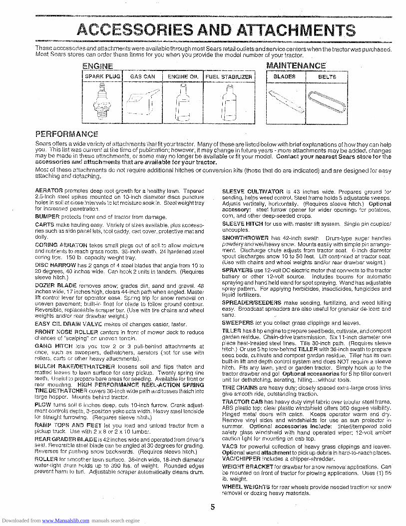
ESSORIES AND ATTAC ENTSThese accessories and attachments were available through most Sears retail outlets and service centers when the tractor was purchased.Most Sears stores can order these items for you when you provide the model number of your tractor.
ENGINE
SPARK PLUG GAS CAN FUEL STABiLiZER
MAINTENANCE
BLADES BELTS
PERFORMANCE
Sears offers a wide variety of attachments that fit your tractor. Many of these are listed below with brief explanations of how they can helpyou. This list was current at the time of publication; however, it may change in future years - more attachments may be added, changesmay be made in these attachments, or some may no longer be available or fit your model. Contact your nearest Sears store for theaccessories and attachments that are available for your tractor.
Most of these attachments do not require additional hitches or conversion kits (those that do are indicated) and are designed for easyattaching and detaching.
AERATOR promotes deep root growth for a healthy lawn. Tapered2.5-inch steel spikes mounted on 10-inch diameter discs punctureholes in soil at close intervals to let moisture soak in. Steel weight trayfor increased penetration_
BUMPER protects front end of tractor from damage.
CARTS make hauling easy. Variety of sizes available, plus accesso-ries such as side panel kits, toot caddy, cart cover, protective mat anddolly.
CORING AERATOR takes small plugs out of soil to allow moistureand nutrients to reach grass roots. 36-inch swath. 24 hardened steelcoring tips. 150 lb. capacity weight tray.
DISC HARROW has 2 gangs of 4 steel blades that angle from 10 to20 degrees, 40 inches wide. Can hook 2 units in tandem. (Requiressleeve hitch,)
DOZER BLADE removes snow; grades dirt, sand and gravel. 48inches wide, 17 inches high, clears 44-inch path when angled. Masterlift control lever for operator ease. Spring trip for snow removal onuneven pavement; built-in float for blade to follow ground contour,Reversible, replaceable scraper bar. (Use with tire chains and wheelweights and/or rear drawbar weight.)
EASY OHL DRAIN VALVE makes oil changes easier, faster.
FRONT NOSE ROLLER canters in front of mower deck to reducechances of "scalping" on uneven terrain.
GANG HF['OH lets you tow 2 or 3 pUll*behind attachments atonce, such as sweepers, dethatchers, aerators (not for use withrollers, carts or other heavy attachments).
MULCH RAKE/DETHATCHER loosens soil and flips thatch andmatted leaves to lawn surface for easy pickup. Twenty spring tineteeth. Useful to prepare bare areas for seeding. Available for front orrear mounting. HiGH PERFORMANCE REEL=ACTION SPRINGTINE DETHATCHER covers 36-inch wide path and tosses thatch intolarge hopper. Mounts behind tractor.
PLOW turns soil 6 inches deep, cuts 10-inch furrow. Crank adjust-ment controls depth, 3-position yoke sets width. Heavy steel lands!defor straight furrowing. (Requires sleeve hitch.)
RAMP TOPS AND FEET let you load and unload tractor from apickup truck. Use with 2 x 8 or 2 x 10 lumber.
REAR GRADER BLADE is 42 inches wide and operated from driver'sseat. Reversible steel blade can be angled at 30 degrees for grading.Reverses for pushing snow backwards. (Requires sleeve hitch.)
ROLLER for smoother lawn surface. 36-inch wide, 18-inch diameterwater-tight drum holds up to 390 Ibm. of weight. Rounded edgesprevent harm to turf. Adjustable scraper automatically cleans drum.
SLEEVE CULTWATOR is 43 inches wide. Prepares ground forseeding, helps weed control. Steel frame holds 5 adjustable sweeps.Adjusts vertically, horizontally. (Requires sleeve hitch.) Optionalaccessory: steel furrow opener for wider openings for potatoes,corn, and other deep-seeded crops.
SLEEVE HITCH for use with master lift system. Single pin couples/uncouples.
SNOWTHROWER has 42-inch swath. Drum-type auger handlespowdery and wet/heavy snow. Mounts easily with simple pin arrange-ment. Discharge chute adjusts from tractor seat. 6qnch diameterspout discharges snow 10 to 50 feet. Lift controlled at tractor seat.(Use with chains and wheel weights and/or rear drawbar weight.)
SPRAYERS use 12wott DC electric motor that connects to the tractorbattery or other 12wolt source. Includes booms for automaticspraying and hand held wand for spot spraying. Wand has adjustablespray pattern. For applying herbicides, insecticides, fungicides andliquid fertilizers.
SPREADER/SEEDERS make seeding, fertilizing, and weed killingeasy. Broadcast spreaders are also useful for granular de-icers andsand.
SWEEPERS let you collect grass clippings and leaves.
TILLER has 8 hp engine to prepare seed beds, cultivate, and compostgarden residue. Chain-drive transmission. Six 11-inch diameter onepiece heat-treated steel tines. Tills 30-inch path. (Requires sleevehitch.) Or use 5 hp tow-behind TILLER with 36-inch swath to prepareseed beds, cultivate and compost garden residue. Tiller has its ownbuilt-in lift and depth control system and does NOT require a sleevehitch. Fits any lawn, yard or garden tractor. Simply hook up to thetractor drawbar and go! OptionaU accessories for 5 hp tiller convertunit for dethatching, aerating, hilling...without tools.
TiRE CHAINS are heavy duty; closely spaced extra-large cross linksgive smooth ride, outstanding traction.
TRACTOR CAB has heavy duty vinyl fabric over tubular steel frame,ABS plastic top; clear plastic windshield offers 360 degree visibility.Hinged metal doors with catch. Keeps operator warm and dry.Remove vinyl sides and windshields for use as sun protector insummer, OptionaJ accessories incUude: tinted/tempered solidsafety glass windshield with hand operated wiper; 12-volt ambercaution light for mounting on cab top.
VACS for powerful collection of heavy grass clippings and leaves.Optional wand attachment to pick up debris in hard-to=reach places_VAC/CHIPPER includes a chipper-shredder.
WEIGHT BRACKET for drawbar for snow removal applications, canbe mounted on front of tractor for plowing applications. Uses (1) 55lb. weight.
WHEEL WEIGHTS for rear wheels provide needed traction for snowremoval or dozing heavy materials.
5
Downloaded from www.Manualslib.com manuals search engine

CONTENTS ,OF E PACK
Parts Bag contents shown full size......... 3
=
(1) Shoulder Bolt 5/16-18
(1) Knob
(1) Washer 17/32 x 1-3/!6 x 12 Gauge
_ etainer SpringsDouble Loop
=
(4) Retainer SpringsSingle Loop
(2) Hex Bolts 1/4-20 x 3/4
(2) Washers 9/32 x 5/8 x 16 Ga.
(2) Hex Nuts 1/4-20
(2) Lock Washers 1/4
(2) Wing Nuts 1/4-20
Parts packed separately in carton..... .- =
Seat
©
Battery acid
6
Steering Wheel
I 1Parts Bag
Battery
Owner's Manual
Parts bag contents not shown full size_ . =
(2) Gauge Wheels
(2) Shoulder Bolts
_t Link Assemblies
©(2)
(2) Washers Lock Nuts3/8 x 7/8 x 14 Gauge
(2) Battery Carriage Bolts 1/4-20 x 7-1/2
Steering Wheel insert
Terminal Guard
15° Slope Sheet...... =
(2) Keys
SteeringSleeve
/ \
r
Battery Capsand Instructions
Downloaded from www.Manualslib.com manuals search engine

BLYYour newtractor has been assembled at the factory with the exception of those parts left unassembled for shipping purposes,To ensure safe and proper operation of your tractor all parts and hardware you assemble must be tightened securely. Usethe correct tools as necessary to insure proper tightness,
TOOLS REQUIRED FOR ASSEMBLY
A socket wrench set will make assembly easier. Standardwrench sizes are listed.
(2) 7/16" wrenches Tire pressure gauge
(1) 1/2" wrench Utility knife
(1) 9/16" wrench
(1) 3/4" socket with drive ratchet
When right or left hand is mentioned in this manua, itmeans when you are in the operating position (seatedbehind the steering wheel).
TO REMOVE TRACTOR FROM CARTON
UNPACK CARTON
® Remove all accessible loose parts and parts cartonsfrom carton (See page 6).
® Cut, from top to bottom, along lines on all four cornersof carton, and lay panels flat.
o Remove mower and packing materials.
o Check for any additional loose parts or cartons andremove.
BEFORE ROLLING TRACTOR OFF SKID
STEERING WHEEL iNSERT
_jHEX BOLT
LOCK WASHER
,_!;,_// LARGE FLATWASHER
STEERINGWHEEL
STEERINGSHAFT
STEERINGSLEEVE
ATTACH STEERING WHEEL (See Fig. 1)
* Remove hex bolt, lock washer and large flat washerfrom steering shaft.
, Position front wheels of the tractor so they are pointingstraight forward,
o Slide steering sleeve over steering shaft,
o Position steering wheel so cross bars are horizontal(left to right) and slide onto steering wheel adapter.
o Secure steering wheel to steering shaft with hex bolt,Iockwasher and large flat washer previously removedTighten securely.
Snap steering wheel insert into center of steeringwheel.
Remove protective plastic from tractor hood and grill.
IMPORTANT: CHECK FOR AND REMOVE ANY STAPLESIN SKID THAT MAY PUNCTURE TIRES WHERE TRACTORIS TO ROLL OFF SKID.
FIG. 1
TO ROLL TRACTOR OFF SKiD (See Fig, 7)
o Raise attachment lift lever to its highest position.
o Release parking brake by depressing clutch/brakepedal.Place gearshift lever in neutral (N) position.
® Rol! tractor backwards off skid,
7
Downloaded from www.Manualslib.com manuals search engine

ASSEM LYHOW TO SET UP YOUR TRACTOR
PREPARE BATTERY (See Fig, 2)
CAUTION: Wear eye and face shield.
Wash Hands or clothing immediately ifaccidentally in contact with battery acid.
Do not smoke. Fumes from chargedbattery acid are e×pmosive.
Read the instructions included with thebattery vent caps. Always wear gloves,c_othing and goggles to protect yourHands, skin and eyes.
Your tractor has a battery charging system which is suffi-cient for normal use. However, periodic charging of thebattery with an automotive charger wilt extend its life.
o See instructions packed with vent caps in parts bag.
Fill battery with acid. Fill each cell until it reaches thebottom of the vent wells. Do not overfill.
Allow battery to stand and settle for at least thirtyminutes. After standing, check the battery cell acidlevel. If below the vent wells, add more acid until thecorrect level is reached.
While battery is standing (after adding acid) and later, whilebattery is being charged, continue with assembly of unit.
iMPORTANT: TO MAXIMIZE THE LIFE OF YOURBATTERY, IT IS NECESSARY THAT THE BATTERY BECHARGED BEFORE USE. FAILURE TO CHARGEBATTERY CAN RESULT IN A SHORTENED BATTERYLIFE.
o Charge battery at a rate of 6 amperes for 1 hour. Usea 12 volt battery charger. Observe all safety precau-tions required for battery charging.
o Check the acid level after the battery is charged. If theacid has fallen below the correct level, add distilled oriron free water_
Install the vent caps to cover the vent wells. Wash thetop of the battery with water to remove any acid, thenwipe dry.
® Check battery case for leakage to make sure that nodamage has occurred in handling.
• Dispose of excess battery acid. Neutralize acid fordisposal by adding it to two gallons of water in a fivegallon plastic container. Stir with a wooden or plasticpaddle while adding baking soda unti! the addition ofmore soda causes no more foaming.
o Follow instructions on how to install battery.
INSTALL SEAT (See Fig. 3)Adjust seat before tightening adjustment knob.
Remove cardboard packing on seat pan.
o Place seat on seat pan and assemble shoulder bolt.
• Assemble adjustment knob and flat washer loosely.Do not tighten.
, Tighten shoulder bolt securely.
• Lower seat into operating position and sit on seat.
o Slide seat until a comfortable position is reached whichallows you to press clutch/brake pedal all the waydown.
o Get off seat without moving its adjusted position.
o Raise seat and tighten adjustment knob securely.
SEAT PAN
SHOULDERBOLT
SEAT
\
FLAT WASHER
ADJUSTMENTKNOB
FIG. 3
CHECK TIRE PRESSURE
The tires on your tractor were overinflated at the factory forshipping purposes. Correct tire pressure is important forbest cutting performance.
• Reduce tire pressure to PSI shown in "PRODUCTSPECIFICATIONS" on page 3 of this manual.
CHECK BRAKE SYSTEM
After you learn how to operate your tractor, check to seethat the brake is properly adjusted. See "TO ADJUSTBRAKE" in the Service and Adjustments section of thismanual.
CUT AWAY ViEW _ VENT CAP
I_ _-_]>._ _ _@/ CELL ACiD
FiG. 2 8
Downloaded from www.Manualslib.com manuals search engine

LYINSTALL MOWER AND DRIVE BELT(See Figs. 4 and 7}Be sure tractor is on level surface. Engage parking brake.o Cut and remove tie down securing anti-sway bar.
Swing anti-sway bar to left side of mower deck., Relieve idler tension from belt. Push idler forward and
place a block (standard wood 2 x 4 or equivalent)behind idler pulley.
® Slide mower under tractor with discharge guard to rightside of tractor.
o Swing L.H. gauge wheel bar forward by removing rearretainer spnng and pin.Install one front link in top hole of the L.H. front mowerbracket and L.H. front suspension bracket. Retain withtwo single loop retainer springs as shown.Slide right side of mower deck forward, toward R.H.front tire.
IMPORTANT: CHECK BELT FOR PROPER ROUTINGINALL MOWER PULLEY GROOVES. INSTALL BELT INTOELECTRIC CLUTCH PULLEY GROOVE.
o Install second front link in the top hole of the R.H. frontmower bracket and R.H front suspension bracket.Retain with two single loop retainer springs as shown.
• Carefully remove block from behind idler pulley.Turn height adjustment knob counterclockwise unti! itstops.
o Lower mower linkage with attachment lift lever.
o Place the suspension arms on inward pointing deckpins. If necessary, rock and raise front of mower toalign deck pins with the holes in suspension arms.Retain with double loop retainer springs.
- Connect anti-sway bar to chassis bracket under leftfootrest and retain with double loop retainer spring.Turn height adjustment knob clockwise to removeslack from mower suspension.
® Raise deck to highest position.• Swing L.H. gauge wheel bar back towards rear of
mower and secure with pin and retainer spnng re-moved earlier.
o Assemble gauge wheels as shown using long shoulderbolts, 3/8 washers and nuts. Tighten securely.
® Adjust gauge wheels before operating mowerasshownin the Operation section of this manual.
CHECK DECK LEVELNESS
For best cutting results, mower housing should be properlyleveled. See "TO LEVEL MOWER HOUSING" in theService and Adjustments section of this manual.
CHECK FOR PROPER POSiTiON OF ALLBELTS
See the figures that are shown for replacing motion, mowerdrive, and mower blade drive belts in the Service andAdjustments section of this manual. Verify that the belts arerouted correctly.
CHASSISBRACKET
\\
\DOUBLE LOOP \RETAINER SPRING
\ \
L.H. GAUGE "_WHEEL BAR
SHOULDERBOLT
NUT
3/8 WASHER
ANTI-SWAYBAR
iDLERPULLEY
GAUGEWHEEL
DOUBLE LOOPRETAINER SPRING(inward pointingdeck pins)
BLOCK(Wood2x4orequiv.)
DISCHARGEGUARD
SUSPENSION FRONTARMS LINKS
FRONT
BRACKET
CLUTCHPULLEY
FRONTSUSPENSIONBRACKET
LOOP RETAINERSPRINGS
FRONT MOWERBRACKET
tF_Go4 9
Downloaded from www.Manualslib.com manuals search engine

ASSEMBLYINSTALL BATTERY (See Figs, 5 and 6)
CAUTION: Do not short battery termi-nares°Before installing battery, removemetam bracelets, wristwatch bands,rings, etc°
Positive terminal must be connectedfirst to prevent sparking from acciden-tal grounding.
- Lift hood to raised position.
o Be sure battery drain tube has not come loose and issecurely attached to drain in battery tray.
o Lower battery into battery tray with terminals to front oftractor.
o First connect RED battery cable to positive (+) batteryterminal with hex bolt, flat washer, lock washer and hexnut as shown. Tighten securely.
o Connect BLACK grounding cable to negative (-) batteryterminal with remaining hex bolt, flat washer, lockwasher and hex nut. Tighten securely.
o Slide the two battery bolts through the terminal guardand start the wing nuts onto the threads.
° Position terminal guard over battery as shown, lowerbattery bolts into key holes and slide square shafts ofbattery bolts into slots of key holes.
Tighten wing nuts by hand making sure battery boltsreman in slots of the key holes in the battery support.
o Be sure terminal access doors are closed.
Use terminal access doors for:
• Inspection for secure connections (to tighten hard-ware).
Inspection for corrosion.
® Testing battery.
o Jumping (if required).
o Periodic charging.
HEX
FLAT WASHER/
/ (POSITWE)/ / RED CABLE
HEX BOLT
LOCK WASHER
NEGATIVE)BLACK CABLE
DRAIN TUBE
KEY HOLE\
\
ACCESSDOORS
VENTCAPS
BATTERY TRAY
FIG. 6
v" CHECKMSTBEFORE YOU OPERATE AND ENJOY YOUR NEWTRACTOR, WE WISH TO ASSURE THAT YOU RECEIVETt lE BES T PERFORMANCE AND SA TISFA CTION FROMTHIS QUALITY PRODUCT,
PLEASE REVIEW THE FOLLOWING CHECKLIST:
,/ All assembly instructions have been completed.
¢' No remaining loose parts in carton.
v' Battery is properly prepared and charged. (Minimum1 hour at 6 amps).
,/ Seat is adjusted comfortably and tightened securely.
,/ All tires are properly inflated. (Forshipping purposes,the tires were overinfiated at the factory).
v" Be sure mower deck is properly leveled side-to-side/front-to-rear for best cutting results. (Tires must beproperly inflated for leveling).
,/ Check mower and drive belts. Be sure they are routedproperly around pulleys and inside all belt keepers.
v" Check wiring. See that all connections are still secureand wires are properly clamped.
WHILE LEARNING HOW TO USE YOUR TRACTOR,PAY EXTRA A TTEN TION TO THE FOL L0 WING IMPOR-TANT ITEMS:
,/ Engine oil is at proper level.
,/ Fuel tank is filled with fresh clean, regular unleadedgasoline.
v" Become familiar with all controls - their location andfunction. Operate them before you start the engine.
v" Be sure brake system is in safe operating condition.
FtGo 5
10
Downloaded from www.Manualslib.com manuals search engine

ERATIONKNOW YOUR TRACTOR
READ THiS OWNER'S MANUAL AND SAFETY RULES BEFORE OPERATING YOUR TRACTOR
Compare the illustrations with your tractor to familiarize yourself with the locations of various controls and adjustments, Savethis manual for future reference,
AMMETER
CHOKE CONTROL
LIGHT SWITCH
CLUTCH/BRAKEPEDAL
THROTTLECONTROL
ATTACHMENT CLUTCH SWITCHLiFT LEVER\ iGNiTiON SWITCH
LIFT LEVER
PARKING BRAKELEVER
HEIGHTADJUSTMENTKNOB
.//
//
//
#
GEARSHIFT LEVER
FIG, 7
Our tractors conform to the safety standards of the American National Standards Institute.
RANGE SHIFTLEVER
ATTACHMENT CLUTCH SWITCH- Used to engage mowerblades or other attachments mounted to your tractor.UFT LEVER- Used to raise and lower mower deck or otherattachments mounted to your tractor.
LIFT LEVER PLUNGER - Used to release attachement liftlever when changing its position.
CLUTCH!BRAKE PEDAL - Used for declutching andbraking the tractor and starting the engine.
GEARSHIFT LEVER oSelects the speed and direction oftractor,
THROTTLE CONTROL - Used to control engine speed.
11
RANGE SHIFT LEVER - Allows high (H) or low (L) speedfor all forward and reverse gears.
IGNITSON SWITCH - Used to start and stop the engine.
AMMETER - Indicates battery charging (+) or discharging(4.UGHT SWITCH - Turns the headlights on and off.
PARKmNG BRAKE LEVER - Locks clutch/brake pedal intothe brake position,
CHOKE CONTROL - Used when starting a cold engine,
HEIGHT ADJUSTMENT KNOB- Used to adjust the mowerheight.
Downloaded from www.Manualslib.com manuals search engine

OPERATI= _
The operation of any tractor can resumt in foreign objects thrown into the eyes, which can resumtin severe eye damage. Always wear safety g_asses or eye shieJds white operating your tractoror performing any adjustments or repairs, We recommend a wide vision safety mask for overthe spectacles or standard safety glasseso
HOW TO USE YOUR TRACTOR
TO SET PARKING BRAKE (See Fig. 8)• Depress clutch/brake pedal into full "BRAKE" position
and hotd.
Place parking brake lever in "ENGAGED" position andrelease pressure from clutch/brake pedal. Pedal shouldremain in "BRAKE" position° Make sure parking brakewill hold vehicle secure..
ATTACHMENTCLUTCH
iGNiTiON KEY SWITCHPARKING BRAKE "ENGAGED""ENGAGED" POSITIONPOSiTiON
CHOKE
THROTTLECONTROL
LEVER"DISENGAGED"POSITION
LEVER
GEARSHIFT
HEIGHT LEVERCLUTCH/ \ ADJUSTMENT
BRAKE \ KNOB \PEDAL \ "DaSENGAGED""BRAKE .... DRIVE" POSNTIONPOSKTJON POSITION
FIG. 8
STOPPING (See Fig, 8)MOWER BLADES -- Move attachment clutch switch to "DISENGAGED"
position.GROUND DRIVE -
, Depress clutch/brake pedal into full "BRAKE" position.* Move gearshift lever to neutral (N) position.ENGINE -
, Move throttle control to slow (,_) position,
NOTE: Failure to move throttle control to slow (,_)position and allowing engine to idle before stopping maycause engine to "backfire".
o Turn ignition key to "OFF" position and remove key.Always remove key when leaving tractor to preventunauthorized use.
Never use choke to stop engine.
NOTE: Under certain conditions when tractor is standingidle with the engine running, hot engine exhaust gases maycause "browning" of grass. To eliminate this possibility,always stop engine when stopping tractor on grass areas.
CAUTmON: Always stop tractor com-pletely, as described above, before leavoing the operator's position; to emptygrass catcher, etc.
TO USE THROTTLE CONTROL (See Fig, 8)Always operate engine at full throttle., Operating engine at less than full throttle reduces the
battery charging rate.o Full throttle offers the best mower performance.
TO USE CHOKE CONTROL (See Fig, 8)Use choke control whenever you are starting a cold engine.Do not use to start a warm engine.o To engage choke control, pull knob out. Slowly push
knob in to disengage.
TO MOVE FORWARD AND BACKWARD(See Fig. 8)The direction and speed of movement _scontrolled by thegearshift lever.o Start tractor with clutch/brake pedal depressed and
gearshift lever in neutral (N) position.- Move gearshift and range shift levers to desired posi-
fion.
° Slowly release clutch/brake pedal to star! movement.aMPORTANT: BRING TRACTOR TO A COMPLETE STOPBEFORE SHIFTING OR CHANGING GEARS. FAILURETO DO SO WILL SHORTEN THE USEFUL LiFE OF YOURTRANSAXLE
TO ADJUST MOWER CUTTING HEIGHT(See Fig. 8)
The cutting height is controlled by turning the height adjust-ment knob in desired direction.
o Turn knob clockwise (f-1) to raise cutting height.o Turn knob counterclockwise (V'_) to lower cutting
height.The cutting height range is approximately 1-1/4" to 4-1/4".The heights are measured from the ground to the blade tipwith the engine not running. These heights are approxi-mate and may vary depending upon soil conditions, heightof grass and types ol grass being mowed.• The average lawn should be cutto approximately 2-1/2
inches during the cool season and to over 3 inchesduring hot months. For healthier and better lockinglawns, mow often and after moderate growth.
o For best cutting performance, grass over 6 inches inheight should oe mowed twice. Make the first cutrelatively high; the second to desired height.
12
Downloaded from www.Manualslib.com manuals search engine

OP RAT
TO ADJUST GAUGE WHEELS (See Fig. 9)
® Adjust mower to desired cutting height.® Lower mower with lift control. Remove rear retainer
spring and clevis pin which secure each gauge wheel.
- Lower gauge wheels to ground. Raise gauge wheelsslightly to align holes in bracket and gauge wheel barand insert clevis pins. Gauge wheels should be slightlyoff the ground.
Replace retainer springs into clevis pins.
RETAINERSPRING
CLEVIS PIN
GAUGE WHEEL
GAUGEWHEEL
TO OPERATE MOWER (See Figs. 7 and 8)
Your unit is equipped with an operator presence sensingswitch. Any attempt by the operator to leave the seat withthe engine running and the attachment clutch engaged willshut off the engine.
o Select desired height of cut.o Lower mower with attachment lift control.
o Start mower blades by engaging attachment clutchcontrol.
o TO STOP MOWER BLADES - disengage attachmentclutch control.
CAUTION: Do not operate the mower _without either the entire grass catcher,on mowers so equipped, or the dis-charge guard in place.
RUNNER
_DISCHARGEGUARD
TO OPERATE ON HILLS
CAUTION: Do not drive up or downhills with slopes greater than 15 anddo not drive across any slope.
• Choose the slowest speed before starting up or downhills.
o Avoid stopping or changing speed on hills.• tf slowing is necessary, move throttle control lever to
slower position.If stopping is absolutely necessary, push clutch/brakepedal quickly to brake position and engage parkingbrake°
Move gearshift lever to I st gear and range shift lever tolow (L) position. Be sure you have allowed room for unitto roll slightly as you restart movement.To restart movement, slowly release parking brake andclutch/brake pedal.
• Make all turns slowly.
TO TRANSPORT
o Raise attachment lift to highest position with attach-ment lift control,
,, When pushing or towing yourtractor, be sure gearshiftlever is in neutral (N) position.
o Do not push or tow tractor at more than five (5) MPHNOTE: To protect hood from damage when transportingyour tractor on atruck or atrailer, be sure hood is closed andsecured totractor. Use an appropriate means of tying hoodto tractor (rope, cord, etc.).
BEFORE STARTING THE ENGINE
CHECK ENGINE OIL LEVEL (See Fig. 11)- The engine in your tractor has been shipped from the
factory, already filled with summer weight oil.® Check engine oil with tractor on level ground.
Remove oil fill cap/dipstick and wipe clean, reinsert thedipstick and push it all the way down into the tube, waitfor a few seconds, remove and read oil level. If,necessary, add oil until "FULL" mark on dipstick isreached. Do not overfill.
, For cold weather operation you should change oil foreasier starting (See "OIL VISCOSITY CHART" in theCustomer Responsibilities section of this manual).To change engine oil, see the Customer ResponsibiIFties section in this manual.
OIL FILL CAP/DIPSTICK
FiG. 10 FIG. 11
13
Downloaded from www.Manualslib.com manuals search engine

OPERATmON
ADD GASOUNE
Fill fuel tank. Use fresh, clean, regular unleadedgasoline. (Use of leaded gasoline will increase carbonand lead oxide deposits and reduce valve life).
iMPORTANT: WHEN OPERATING IN TEMPERATURESBELOW 32°F(0°C), USE FRESH, CLEAN WINTER GRADEGASOLINE TO HELP iNSURE GOOD COLD WEATHERSTARTING.
WARNING: Experience indicates that alcohol blendedfuels (called gasohol or using ethanol or methanol) canattract moisture which leads to separation and formation ofacids during storage. Acidic gas can damage the fuelsystem of an engine while in storage. To avoid engineproblems, the fue! system should be emptied before stor-age of 30 days or longer. Drain the gas tank, start theengine and let it run until the fuel lines and carburetor areempty. Use fresh fuel next season. See Storage Instruc-tions for additional information. Never use engine orcarburetor charier products in the fuel tank or permanentdamage may occur.
CAUTION: Fill to bottom of gas tankfiller neck. Do not overfiJL Wipe off anyspilled oH or fuel Do not store, spill oruse gasomine near an open flame°
TO START ENGINE (See Fig. 8)
When starting engine for the first time or if engine has runout of fuel, it will take extra cranking time to move fuel fromthe tank to the engine.
Depress clutch!brake pedal aria set parking brake.
Place gearshift lever in neutral (N) position.
® Move attachment clutch to "DISENGAGED" position.
Pult choke control out to choke (1",1)position for coldengine start For warm engine start do not use chokecontrol.
o Move throttle contro to midway between fast (@_)andslow (_) positions.
Insert key into ignition and turn key clockwise to"START"position and release key as soon as eng ne starts. Donot run starter continuously for more than fifteenseconds per minute. If engine does not start afterseveral attempts, move throttle control to fast (,@)position, wait a few minutes and try again.
• When engine starts, slowly push choke control in.
Move throttle control to fast (,_) position.
Allow engine to warm up for a Iew minutes beforeengaging drive or attachments.
NOTE: If at a high altitude tabove 3000 feet) or in coldtemperatures (below 32°F} the carburetor fuel mixturemay need to be adjusted for best engine performance See"TO ADJUST CARBURETOR' m _ne Service and Adjust-ments section of this manual.
MOWING TIPSTire chains cannot be used when the mower housingis attached to unit.
- Mower should be properly leveled for best mowingperformance. See "TO LEVEL MOWER HOUSING" inthe Service and Adjustments section of this manual.
- Use the runner on the right hand side of mower as aguide. The blade cuts approximately an inch outsidethe runner (See Fig. 10).
o The left hand side of mower should be used for trim-ming.
o Drive so that clippings are discharged onto the areathat has been cut. Have the cut area: to the right of themachine. This wilt result in a more even distribution ofclippings and more uniform cutting.
When mowing large areas, start by turning to the rightso that clippings will discharge away from shrubs,fences, driveways, etco After one or two rounds, mowin the opposite direction making left hand turns untilfinished (See Fig. 12).
• If grass is extremely tall, it should be mowed twice toreduce load and possible fire hazard from dried clip-pings. Make first cut relatively high; the second to thedesired height.
o Do not mow grass when it is wet. Wet grass will plugmower and leave undesirable clumps. Allow grass todry before mowing.
o Always operate engine at full throttle when mowing toassure better mowing performance and proper dis-charge of material. Regulate ground speed by select-ing a low enough gear to give the mower cuttingperformance as well as the quaIity of cut desired.
o When operating attachments, select a ground speedthat will suit the terrain and give best performance ofthe attachment being used.
FIG. !2
14
Downloaded from www.Manualslib.com manuals search engine

CUSTOME RESPONSiBiLiTiES
MAINTENANCE SCHEDULEFILL IN DATESAS YOU COMPLETEREGULAR SERVICE SERVICE DATES
Check Brake OperationCheck Tire Pressure
T i Check for Loose Fasteners
Sharpen!ReplaceMower BladesAC I Lubrication ChartT I Check Battery,Level/Recharge
O Clean Battery and Terminals. Check Transaxle cooling
Adjust Blade Belt(s) Tension
Adjust Motion Drive Belt(s) Tension
E!NGJ
NEl
Check Engine Oil Level
Change Engine Oil
Clean Air Filter
Clean Air Screen
Inspect Muffler/Spark Attester
Replace Oil Filter (If equipped)
Clean Engine Cooling Fins
Replace Spark Plug
Replace Air Fitter Paper Cartridge
Replace Fuel Filter
Change more often when operating under a heaw load or in high ambient temperatures.- Service more often when operating in dirty or dusty conditions.
GENERAL RECOMMENDATIONS
The warranty on this tractor does not cover items that havebeen subjected to operator abuse or negligence. Toreceive fu!l value from the warranty, operator must maintaintractor as instructed in this manual.
Some adjustments wit! need to be made periodically toproperly maintain your tractor.
All adjustments in the Service and Adjustments section ofthis manual should be checked at least once each season.
Once a year you should replace the spark plug, cleanor replace air filter, and check blades and belts forwear, A new spark plug and clean air filter assureproper air-fuel mixture and help your engine run betterand last longer.
BEFORE EACH USE
o Check engine oil level.
o Check brake operation.
,, Check tire pressure.
Check for loose fasteners.IMPORTANT: DO NOT OIL OR GREASE THE PIVOTPOINTS WHICH HAVE SPECIAL NYLON BEARINGS.VISCOUS LUBRICANTS WILL ATTRACT DUST AND DI RTTHAT WILL SHORTEN THE LIFE OF THE SELF-LUBRICATING BEARINGS. tF YOU FEEL THEY MUSTBE LUBRICATED, USE ONLY A DRY, POWDEREDGRAPHITE TYPE LUBRICANT SPARINGLY.
3 - tf equipped with oil filter, change oil every 50 hours.4 - Replace blades more often when mowing in sandy soil.
5 - If equipped with adjustable system.
LUBRICATION CHART
(_)TIE ROD BALL JOINTS
(_) FRONT WHEEL ::::::: ::::: : FRONT WHEEL Q
SECTOR GEAR ENGINE (_)TEETH
TRANSAXLEFLUID
15
(_SAE 30 MOTOR OiL API. SG
(_) GENERAL PURPOSE GREASE
(_) REFER TO CUSTOMER RESPONSIBILITIES "ENGINE" SECTION
OSPRAY SILICONE LUBRICANT (MOVE BOOTS TO LUBRICATE)
Downloaded from www.Manualslib.com manuals search engine

l
CUSTOME RESPO LITIES
TRACTOR • The blade can be sharpened with a file or on a grinding
Always observe safety rules when performing any mainte-nance.
BRAKE OPERATION
If unit requires more than six (6) feet stopping distance athigh speed in highest gear, then brake must be adjusted.(See "TO ADJUST BRAKE" in the Service and Adjust-ments section of this manual).
TIRES
,, Maintain proper air pressure in al! tires (See "PROD-UCT SPECIFICATIONS" on page 3 of this manual).
o Keep tires free of gasoline, oil, or insect control chemi-cals which can harm rubber.
o Avoid stumps, stones, deep ruts, sharp objects andother hazards that may cause tire damage.
BLADE CARE
For best results mower blades must be kept sharp. Re-place bent or damaged blades.
BLADE REMOVAL (See Fig. 13)
° Raise mower to highest position to allow access toblades.
• Remove hex bolt, lockwasher and flat washer securingblade.
o Install new or resharpened blade with trailing edge uptowards deck as shown;
o Reassemble hex bolt, lock washer and flat washer inexact order as shown.
o Tighten bolt securely (30-35 Ft. Lbs. torque).IMPORTANT: BLADE BOLT IS GRADE 8 HEATTREATED.
NOTE: We do not recommend sharpening blade- but if youdo, be sure the blade is balanced.
MANDRELBLADE ASSEMBLY
LOCK WASHER
FIG. 13
TO SHARPEN BLADE (See Fig° 14)
Care should be taken to keep the blade balanced. Anunbalanced blade will cause excessive vibration and even-tual damage to mower and engine.
wheel. Do not attempt to sharpen while on the mower.
• To check blade balance, you will need a 5/8" diametersteel bolt, pin, or acone balancer. (When using aconebalancer, follow the instructions supptied with bal-ancer).
o Slide blade on to an unthreaded portion of the steel boltor pin and hold the bolt or pin parallel with the ground.If blade is balanced, it should remain in a horizontalposition. If either end of the blade moves downward,sharpen the heavy end until the blade is balanced.
NOTE: Do not use a nail for balancing blade. The lobes ofthe center hole may appear to be centered, but are not.
CENTER HOLE
518" BOLT BLADE
OR PIN j
FIG. ! 4
V-BELTS
Check V-belts for deterioration and wear after 100 hoursand replace if necessary. The belts are not adjustable.Replace belts if they begin to slip from wear.
TRANSAXLE COOMNG
Keep transaxte free from build-up of dirt and chaff whichcan restrict cooling.
CHECK TRANSAXLE OIL LEVEL
(See Fig. 15)• Block up rear axle securely or use a tractor jack.
o Remove left rear wheel by removing hub bolts.
o Remove filler plug from transaxle. Oil level must beeven with plug threads. If necessary, fill with SAE 30motor oil, API-SG. Replace filler plug.
o Reassemble wheel to hub.
• For approximate capacity see "PRODUCT SPECIFI-CATIONS" on page 3 of this manual.
oo
TRANSAXLEFILLER PLUG
NG. 15
16
Downloaded from www.Manualslib.com manuals search engine

CUSTO Sl LITIES
BATTERY (See Fig. 16)Your unit has a battery charging system which is sufficientfor normal use However, periodic charging of the batterywith an automotive charger will extend its life,
- Acid solution level in each battery cell should be evenwith bottoms of vent wells. Add only distilled or iron freewater if necessary. Do not overfill.
° Keep battery and terminals clean.
Keep battery bolts tight.
Keep vent caps tight and small vent holes in caps open.
o Recharge at 6 amperes for 1 hour.TO CLEAN BATTERY AND TERMINALS -
Corrosion and dirt on the battery and terminals can causethe battery to "leak" power.
Remove terminal guard.
• Disconnect BLACK battery cable first then RED bat-tery cable and remove battery from tractor.
• Wash battery with solution of four tablespoons ofbaking sodato one gallon of water. Be careful notto getthe soda solution into the cells.
o Rinse the battery with plain water and dry.
• Clean terminals and battery cable ends with wire brushuntil bright.
o Coat terminals with grease or petroleum jelly.
Reinstall battery (See "INSTALL BATTERY" in theAssembly section of this manual).
CUT AWAY VIEW
L__q::::C:=:ZT__I j VENTvENTCAP
WELL
BATTERYCELL ACIDLEVEL
FiG. 16
ENGmNE
LUBRiCATiON
Only use high quality detergent oi rated with API serviceclassification SG. Select the oil's SAE viscosity gradeaccording to your expected operating temperature.
SAE VISCOSITY GRADES
:)o 30 ° 60 ° 80 _
-20 < - 10° 0' 10' 20' 30' 40 °
qEMPERATURE RANGE AN3 r CiPATED BEFORE NEXT OIL CHANGE
NOTE: Although multi-viscosity oils (5W30, !0W30 etc.)mprove starting in cold weather, these multi-viscosity oilswill result in increased oil consumption when used above32°F. Check your engine oil level more frequently to avoidpossible engine damage from running low on oil.
Change the oil after the first two hours of operation andevery 50 hours thereafter or at least once a year if thetractor is not used for 50 hours in one year.
Check the crankcase oil level before starting the engineand after each eight (8) hours of operation. Tighten oil fillcap/dipstick securely each time you check the oil level.
TO CHANGE ENGINE OIL (See Figs. 17 and 18)
Determine temperature range expected before oil change.All oil must meet API service classification SG.
o Be sure tractor is on level surface.
• Oil wil drain more freely when warm.- Catch oi! in a suitable container,
® Remove oil fill cap/dipstick. Be careful not to allow dirtto enter the engine when changing oil.
• Remove drain plug.
° After oil has drained corn pletely, replace oil drain plugand tighten securely.
Refill engine with oil through oil fill dipstick tube. Pourslowly. Do not overfill. For approximate capacity see"PRODUCT SPECIFICATIONS" on page 3 of thismanual.
Use gauge on oil fill cap/dipstick for checking level, Besure dipstick is in all the way for accurate reading.Keep oil at "FULL" line on dipstick.
OIL DRAIN PLUG
\\\
OIL FILLCAP/DIPSTICK
FIG. 18
FIG, 17
17
Downloaded from www.Manualslib.com manuals search engine
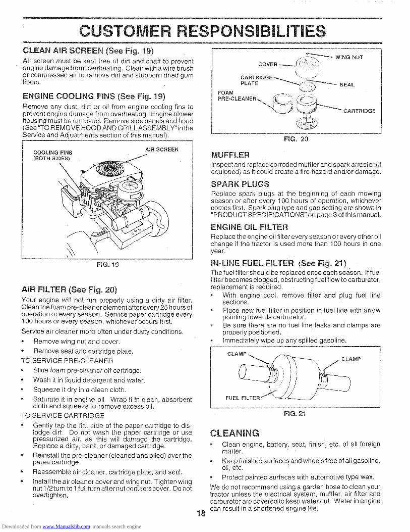
CUSTOME PONSI ILITIESCLEAN AmR SCREEN (See Fig. 19)Air screen must be kept free of dirt and chaff to preventengine damage from overheating. Clean with a wire brushor compressed air to remove dirt and stubborn dried gumfibers.
ENGINE COOLING FINS (See Fig, 19)
Remove any dust, dirt or oil from engine cooling fins toprevent engine damage from overheating. Engine blowerhousing must be removed. Remove side panels and hood(See "TO REMOVE HOOD AND GRILL ASSEMBLY" in theService and Adjustments section of this manual).
WING NUT
CARTRIDGEPLATE _S_'_ SEAL
FOAM _'_J JJ
FIG. 20
COOLING FINS(BOTH S_DES)
A_R SCREEN
\
\
FIG. 19
AIR FmLTER (See Fig. 20)
Your engine will not run properly using a dirty air filter.Clean the foam pre-cleaner element after every 25 hours ofoperation or every season. Service paper cartridge every100 hours or every season, whichever occurs first.
Service air cleaner more often under dusty conditions.
,, Remove wing nut and cover.
• Remove seal and cartridge plate.TO SERVICE PRE-CLEANER
,, Slide foam pre-cteaner off cartridge.
o Wash it in liquid detergent and water.• Squeeze it dry in a clean cloth.
, Saturate it in engine oil. Wrap it in clean, absorbentcloth and squeeze to remove excess oil.
TO SERVICE CARTRIDGE
, Gently tap the flat side of the paper cartridge to dis-lodge dirt. Do not wash the paper cartridge or usepressurized air, as this will damage the cartridge.Replace a dirty, bent, or damaged cartridge.
Reinstall the pre-cleaner (cleaned and oiled) over thepaper cartridge.
® Reassemble air cleaner, cartridge plate, and seal.
,, Install the air cleaner cover and wing nut. Tighten wingnut 1/2turn to 1fullturn after nut contactscover. Do notovertighten.
MUFFLER
inspect and replace corroded muffler and spark arrester (ifequipped) as it could create a fire hazard and/or damage.
SPARK PLUGS
Replace spark plugs at the beginning of each mowingseason or after every 100 hours of operation, whichevercomes first. Spark plug type and gap setting are shown in"PRODUCT SPECIFICATIONS" on page 3 of this manual.
ENGINE OIL FILTERReplace the engine oil filer every season or every other oilchange if the tractor is used more than !00 hours in oneyear.
IN-LINE FUEL FILTER (See Fig. 21)The fue! filter should be replaced once each season. If fuelfilter becomes clogged, obstructing fuel flow to carburetor,replacement is required.o With engine cool, remove filter and plug fuel line
sections.• Place new fuel filter in position in fuel line with arrow
pointing towards carburetor.o Be sure there are no fuel line leaks and clamps are
property positioned.Immediately wipe up any spilled gasoline.
CLAMP
FUEL FILTER
FMGo21
18
CLEANING
° Clean engine, battery, seat, finish, etc. of all foreignmatter.
• Keep finished surfaces and wheels free of all gasoline,oil, etc.
• Protect painted surfaces with automotive type wax.
We do not recommend using a garden hose to clean yourtractor unless the electrical system, muffler, air filter andcarburetor are covered to keep water out. Water in enginecan result in a shortened engine life.
Downloaded from www.Manualslib.com manuals search engine

SERVICE ADJU NTS
CAUTION: BEFORE PERFORMING ANY SERVICE OR ADJUSTMENTS:
Depress dutch/brake pedal fully and set parking brake,- Place gearshift lever in neutral (N) position=o Place attachment ctutch in "DISENGAGED" position.• Turn ignition key "OFF" and remove key.o Make sure the blades and all moving parts have completely stopped,- Disconnect spark plug wire from spark plug and place wire where it cannot come in contact
with plug.
TRACTOR TO LEVEL MOWER HOUSING
TO REMOVE MOWER (See Fig, 22)• Place attachment clutch in "DISENGAGED" position.• Turn height adjustment knob to !owest setting.• Lower mower to its lowest position.• Remove retainer spnng holding anti-swaybar to chas-
sis bracket and disengage antioswaybar from bracket.• Remove retainer springs from suspension arms at
deck and disengage arms from deck., Raise attachment lift to its highest position.• Remove two retainer springs from each front link and
remove links.• Slide mower forward and remove belt from electric
clutch pulley., Slide mower out from under right side of tractor.IMPORTANT: IF AN ATTACHMENT OTHER THAN THEMOWER DECK IS TO BE MOUNTED ON THE TRACTOR,REMOVE THE FRONT LINKS.
TO iNSTALL MOWER
Follow procedure described in "INSTALL MOWER ANDDRIVE BELT" in the Assembly section of this manual,
FRONTSUSPENSIONBRACKETADJUSTMENT \
SUSPENSION NUTS LIFT \ARMS LINKS \
CHASSISBRACKET
FRONT MOWERBRACKET
Adjust the mower while tractor is parked on level ground ordriveway. Make sure tires are properly inflated (See"PRODUCT SPECIFICATIONS" on page 3 of this manual)If tires are over or undednflated, you will not properly adjustyour mower.SIDE-TO-SIDE ADJUSTMENT (See Figs. 22 and 23)- Raise mower to its highest position.• Measure height from bottom of deck cud to ground
level at front corners of mower. Distance "A" should bethe same.
° tf distance "A" needs to be changed, make adjustmenton one side of mower only,
• Raise one side of mower by tightening lift link adjust-ment nut on that side.
Lower one side of mower by loosening lift link adjust-ment nut on that side.
NOTE: Each half turn of adjustment nut will change decklevel about 1/4".
• Recheck level after adjusting.
ELECTRICCLUTCHPULLEY
/RETAINER
SPRING //
ANTFSWAYBAR
FIG. 22
19
RETAINERSPRINGS
FRONTSUSPENSIONBRACKET
MOWERBRACKET
\
\
Downloaded from www.Manualslib.com manuals search engine

SERVICE AND AOJ STMENTS
FRONT-TO-BACK ADJUSTMENT (See Figs. 24 and 25) -iMPORTANT: DECK MUST BE LEVEL SIDE-TO-SIDE. IFTHE FOLLOWING FRONT-TO-BACK ADJUSTMENT ISNECESSARY, BE SURE TO ADJUST BOTH FRONT LINKSEQUALLY SO MOWER WILL STAY LEVEL SIDE-TO°SIDE.To obtain the best cutting results, the mower housingshould be adjusted so the front is approximately 1/8" to 1/2"lower than the rear when the mower is in its highestposition.Check adjustment on right side of tractor. Measure dis-tance ',F" directly in front of and behind the mandrel atbottom edge of mower housing as shown., Before making any necessary adjustments, checkthat
both front links are equal in length:• If links are not equal in length, adjust one link to same
length as other link.To lower front of mower housing, loosen nut"G" on bothfront links an equal number of turns.
® When distance "F" is 1/8" to 1/2" lower at front thanrear, tighten nut"H" against trunnion on both front links.
. To raise front of mower housing, loosen nut "H" fromtrunnion on both front links. Tighten nut "G" on bothfront links an equal number of turns.When distance "F" is 1/8" to 1/2" lower at front thanrear, tighten nut "H" against trunnion on both frontlinks.
NOTE: Each full turn of nut "G" will change dim. "F" byapproximately 3/8"o• Recheck side-to-side adjustment.
TO REPLACE MOWER DRIVE. BELT
MOWER DRIVE BELT REMOVAL (See Fig. 26) o
• Park tractor on a level surface. Engage parking brake.• Remove four screws from L.H. mandrel cover and
remove cover.
Rol! belt over the top of L.H. mandrel pulley.
o Remove belt from electric dutch pulley.
• Remove belt from idler pulleys.
o Remove any dirt or grass clippings which may haveaccumulated around mandrels and entire upper decksurface.
o Check primary idler arm and two idlers to see that theyrotate freely.
o Be sure spring is securely hooked to primary idler armand bolt in mower housing.
MOWER DRIVE BELT INSTALLATION (See Fig. 26) -• Install belt in both idlers. Make sure belt is in both belt
keepers at the idlers as shown.
o Install new belt onto electric clutch pulley.
- Roll belt into upper groove of L.H. mandrel pulley.
Carefully check belt routing making sure belt is in thegrooves correctly and inside belt keepers.
o Reassemble L.H. mandrel cover.
"F" _ _ "F"G ROU N_DL_NE
/Z7Z?77-77777777_/ 7_;:_:(:7 iTZ777-_T77*777777-T/7
FIG. 24
BOTH FRONT LINKS SHOULD BE EQUAL IN LENGTH
NUT "H"
FRONT LINKS
FiG. 25
2O
SCREWSSPRING
FIG, 26
i:iii!_
BOLT IN
HOUSING
Downloaded from www.Manualslib.com manuals search engine

SE CETO REPLACE MOWER BLADE DRIVE BELT(See Fig. 27)Park the tractor on level surface. Engage parking brake,
Remove mowerdrive belt (See'qO REPLACE MOWERDRIVE BELT" in this section of this manual),
o Remove mower (See "TO REMOVE MOWER" in thissection of this manual).
o Remove four screws from R.H. mandrel cover andremove cover. Unhook spring from bolt on mowerhousing.
o Carefully roll belt off R.H. mandrel pulley.- Remove belt from center mandrel pulley, idler pulley,
and L.H. mandrel pulley.o Remove any dirt or grass which may have accumu-
lated around mandrels and entire upper deck surface.• Check secondary idler arm and idler to see that they
rotate freely.Be sure spring is hooked in secondary idler arm andsway-bar bracket.
o Install new belt in lower groove of L.H. mandrel pulley,idler pulley, and center mandrel pulley as shown.
• Roll belt over R.H. mandrel pulley. Make sure belt is inall grooves properly.Reconnect spring to bolt in mower housing and rein-stall R.H. mandrel cover.Reinstall mower to tractor (See"TO INSTALL MOWER"in the Assembly section of this manual).
o Reassemble mower drive belt (See "TO REPLACEMOWER DRIVE BELT" in this section of this manual).
ADJUSTMENTS
CENTERMANDREL
COVER
tSCREW/
iDLER ARM ,°
SPRING j
SWAY-BARBRACKET
iDLERPULLEY
FIG. 27
TO ADJUST ATTACHMENT CLUTCH(See Fig. 28)The electric clutch should provioe years of service. The_tutch has a bulk-in brake that stops the pulley within 53econds. Eventually, the internal brake will wear whichmay cause the mower blades to not engage, or, to not stopas required. Adjustments should be made byyour nearestadthorized service center/department.° Make sure atta chment clutch and ignition switches are
in "OFF" position.° Adjust the three nylon Iocknuts until space between
clutch plate and rotor measures .0t2" at all three slotlocations cut inside of brake plate.
NOTE: After installing a new electric clutch, run tractor atfull throttle and engage and disengage electric clutch 10cycles to wear unclutch plate
NYLON LOCKNUT (3) BRAKE PLATE
FIG, 28
TO ADJUST BRAKE (See Fig. 29)
Your tractor is equipped with an adjustable brake systemwhich is mounted on the left side of the transaxie.
If tractor requires more than six (6)feet stopping distanceat high speed in highest gear, then brake must be adjusted.
• Depress clutch/brake pedal and engage parking brake.
• Measure distance between brake operating arm andnut "A" on brake rod.
- If distance is other than 1-3/4", loosen jam nut and turnnut 'A until distance becomes 1-3/4". Retighten jamnut against nut "A".
• Road test tractor for proper stopping distance as statedabove. Readjust if necessary. If stopping distance isstill greater than six (6) feet in highest gear, furthermaintenance is necessary. Contact your nearest au-thorized service center/department.
WiTH PARKING BRAKE "ENGAGE"
\ NUT "A"
OPERATINGARM NUT
\
FiG, 29
21
Downloaded from www.Manualslib.com manuals search engine

SERVICE AND ADJUSTMENTS
TO REPLACE MOTION DRmVE BELT(See Fig, 30}
Park the tractor on level surface. Engage parking brake.For ease of service there is a belt installation guide decal onbottom of left footrest. It is not necessary to remove mower.BELT REMOVAL-
• Raise hood and disconnect BLACK (grounding) bat-tery cable.
o Set parking brake (to get belt slack).
, Remove mower drive belt from electric clutch pulleyonly (See "TO REPLACE MOWER DRIVE BELT" inthis section of this manual).
Roll motion drive belt Off transaxle pulley.
Roll belt off clutching idler pulleys, then off enginepulley and front V-idler pulley.
• Pull belt out of all belt keepers.BELT INSTALLATION -
Place V part of belt into grooves on engine pulley andfront V-idler, making sure to route belt inside of beltkeepers.
, Put belt coming from V-idler above midspan belt keeper,then onto clutching idler pulleys as shown.
Make sure "V" part of belt engages "V" idler°
Place belt around transaxle pulley, beginning at top."V" part of belt should engage transaxle pulley.
- Place long lower section of belt through loop in midspanbelt keeper.
Check to be sure belt is on proper side of all beltkeepers.
o Reinstall mower drive belt onto electric clutch pulley.
• Release parking brake.IMPORTANT: CHECK BRAKE ADJUSTMENT.
ENGINEPULLEY
TRACTOR VoBELT DRIVE SCHEMATaCVIEWED FROM L;H. SlOE OF TRACTOR
CLUTCHBNG_DLER
BELTCLUTCHINGFLAT gDLER
ABOVE
PULLEY
BELTTWISTS
BELT TRANSAXLEKEEPER PULLEY
VqDLER
AS VIEWED FROM BOTTOM
RG. 30
TO ADJUST STEERING WHEEL ALIGNMENT
If steering wheel crossbars are not horizontal (left to right)when wheels are positioned straightforward, remove steer-ing wheel and reassemble per instructions in the Assemblysection of this manual.
FRONT WHEEL TOE-IN ADJUSTMENT
Front wheel toe-in is required for proper steering operation.Toe-in was set at the factory and adjustment should not benecessary. If parts in the front axle or steering mechanismhave been replaced or damaged, check toe-in and adjustif necessary.
TO CHECK TOE-IN (See Fig. 31) -
• Position front wheeis straight ahead.• Measure distance between wheels at front and rear of
tires (dimensions "A" and "B").Front dimension "A" should be 1/8" to 1/4" less thanrear dimension "B".
TO ADJUST TOE-IN (See Figs. 31 and 32) -
• Loosen jam nuts at adjustment sleeves on tie rod.
• Adjusttieroduntildimenslon"A"isl/8"tol/4"lessthandimension "B".
o Tighten jam nuts securely.
B
_ FRONT OF TRACTOR _
FIG. 31
ADJUSTMENT SLEEVES
TIE ROD
JAM NUTS/\
FIGo 32
FRONT WHEEL CAMBER
The front whee camber is not adjustable on your tractor. Ifdamage has occurred to affect the front wheel camber,contact your nearest authorized service center/depart-ment.
22
Downloaded from www.Manualslib.com manuals search engine

SE CE AN A USTMENTS
TO REMOVE WHEEL FOR REPAIRS
FRONT WHEEL (See Fig. 33) =
• Block up axle securely.
o Remove axle cover, retaining ring and washers to allowwheel removal.
Repair tire and reassemble.
o Replace washers and snap retaining Hng securely inaxle groove.
o Replace axle cover.
WASHERS
RETAINING
RING \
AXLE \
covE_ \
FiG. 33
REAR WHEEL -
o Block rear axle securely.
• Remove five (5) hub bolts to allow wheel removal.
Repair tire and reassemble. Replace and tighten hubbolts securely.
TO START ENGINE WITH A WEAK BATTERYSee Figs. 34 and 35)
CAUTION: Lead-acid batteries gener=ate e×plosive gases. Keep sparks, flameand smoking materials away from bat-teries. Always wear eye protectionwhen around batteries.
If your battery is too weak to start the engine, it should berecharged. If "jumper cables" are used for emergencystarting, follow this procedure:
IMPORTANT: YOUR TRACTOR iS EQUIPPED WITH A 12VOLT NEGATIVE GROUNDED SYSTEM. THE OTHERVEHICLE MUST ALSO BE A 12 VOLT NEGATIVEGROUNDED SYSTEM. DO NOT USE YOUR TRACTORBATTERY TO START OTHER VEHICLES.
TO ATTACH JUMPER CABLES -
o Connect each end of the RED cable to the POSITIVE(+) terminal of each battery, taking care not to shortagainst chassis,
o Connect one end of the BLACK cable to the NEGA-TIVE (-) terminal of fully charged battery.
Connect the other end of the BLACK cable to a panelbolt on the left side of the tractor, away from fuel tankand battery.
TO REMOVE CABLES, REVERSE ORDER -
BLACK cable first from chassis and fully chargedbattery.
o RED cable last from both batteries.
POSTVEI NEGATVE(+) (-)
FiG. 34
PANEL
° °FiG. 35
TO REPLACE HEADLIGHT BULB
- Raise hood.
- Pull bulb holder out of the hole in the backside of thegrill.
o Replace bulb in holder and push bulb holder securelyback into the hole in the backside of the grill.
- Close hood.
INTERLOCKS AND RELAYS
Loose or damaged wiring may cause your tractor to runpoorly, stop running, or prevent it from starting.
Check wiring. See electrical wiring diagram _nRepairParts section of this manual.
TO REPLACE FUSE
Replace with 30 amp automotive-type plug-in fuse, Thefuse holder is located behind the dash,
23
Downloaded from www.Manualslib.com manuals search engine

E CE AND ADJUSTMENTS
TO ADJUST ATTACHMENT LiFT SPIRING(See Fig. 36)• While holding spring bushing with wrench, loosen jam
nut.
• Turn adjustment bolt clockwise to extend spring andreduce lift effort (for heavier attachments).
,, Turn adjustment bolt counterclockwise for lighter at-tachments.
Retighten jam nut against spring bushing.
IMPORTANT: DO NOT ADJUST FOR MAXIMUM SPRINGTENSION WHEN USING LIGHT ATTACHMENTS SUCHAS A MOWER. ADJUST LIFT LEVER SPRING TO AID INLIFTING ATTACHMENT. DO NOT OVERPOWER SPRING.WHEN REMOVING ATTACHMENT, ALWAYS ADJUSTSPRING TENSION TO ITS LOWEST POSITION.
ADJUSTMENT SPRING BUSHINGBOLT
® ATTACHMENTJAM NUT UFT SPRMNG
o ®
FiG. 36
TO REMOVE HOOD AND GRILL ASSEMBLY
(See Fig. 37)• Raise hood.
,, Unsnap headlight wire connector.
• Stand in front of tractor. Grasp hood at sides, tilt towardengine and lift off of tractor°
o To replace, reverse above procedure.
HOOD
//
,/
WIRECONNECTION
/
FNG.37
24
Downloaded from www.Manualslib.com manuals search engine

SERVICE A ADJU ENTS
ENGINE
TO ADJUST THROTTLE CONTROL CABLE(See Fig. 38 & 39)The throttle control has been preset at the factory andadjustment should not be necessary. Check adjustment asdescribed below before loosening cable. If adjustment isnecessary, proceed as follows:
With engine not running, move throttle control lever tofast ('¢ep)position.
o Check that speed control lever is against stop screw. Ifit is not, loosen casing clamp screw and pull throttlecable until lever is against screw. Tighten clamp screwsecurely.
TO ADJUST CARBURETOR (See Fig. 40)
The carburetor has been present at the factory and adjust-ment should not be necessary. However, minor adjustmentmay be required to compensate for differences in fuel.temperature, altitude or load. If the carburetor does notneed adjustment, proceed as follows:
in general, turning the adjusting needles in (clockwise)decreases the supply of fuel to the engine giving a leanerfuel/air mixture. Turning the adjusting needles out (coun-terclockwise) increases the supply of fuel to the engnnegiving a richer fuel/air mixture.IMPORTANT: DAMAGE TO THE NEEDLES AND THESEATS IN CARBURETOR MAY RESULT IF SCREW ISTURNED IN TOO TIGHT.
PRELIMINARY SETTING -
* Be sure you have a clean air filter, and the throttlecontrol cable is adjusted properly (see above).
o With engine off turn idle fuel adjusting needle in (clock-w_se)closing it finger tight and then turn out (counter-clockwise) 1-1/4 turns.
Turn main fuel adjusting needle in (clockwise) closingfinger tight and then turn out (counterclockwise) 1turn.
FINAL SETTING -
o Start engine and allow to warm for five minutes. Makefinal adjustments with engine running and shift/motioncontrol lever in neutral (N) position.
• With throttle control lever in fast ( ,1_ ) position, turnmain fuel adjusting needle in (clockwise) until enginebegins to die then turn out (counterclockwise) untilengine runs rough. Turn needle to a point midwaybetween those two positions
• Idle s_p_eedsetting - With throttle control lever in slow(,_!) position, engine should idle at 1400 RPM. Ifengine idles too slow or fast turn idle speed adjustingscrew in or out until correct idle is attained.
Idle fuel needte setting - With throttle control lever inslow (_) position, _urn idle fuel adjusting needle in(clockwise) until engine begins to die and then turn out(coun[erclockwise) until engine runs rough° Turn needleto a point midway between those two positions.
Recheck idle speed, Readjust if necessary.
25
ACCELERATION TEST -
• Move throttle control lever from slow (-_) to fast (,@)
position. If engine hesitates or dies, turn idle mixturescrew out (counterclockwise) I/8 turn. Repeat test andcontinue to adjust, if necessary, until engine acceler-ates smoothly.
High speed stop is factory adjusted. Do not adjust-damagemay result.
IMPORTANT: NEVER TAMPER WITH THE ENGINEGOVERNOR WHICH IS FACTORY SET FOR PROPERENGINE SPEED. OVERSPEEDING THE ENGINE ABOVETHE FACTORY HIGH SPEED SETTING CAN BEDANGEROUS IFYOUTHINKTHEENGINE-GOVERNEDHIGH SPEED NEEDS ADJUSTING. CONTACT YOURNEAREST AUTHORIZED SERVICE CENTER!DEPARTMENT. WHICH HAS PROPER EQUIPMENT ANDEXPERIENCE TO MAKE ANY NECESSARYADJUSTMENTS.
CASING STOP SCREW SPEED CONTROLCLAMP \ / j" LEVER
/li;?1FIG. 38
STOP
SPEEDCONTROLLEVER
FroG.39
IDLE SPEEDADJUSTINGSCREW -o
FIG, 40
Downloaded from www.Manualslib.com manuals search engine

STORAGE
Immediately prepare your tractor for storage at the end ofthe season or if the tractor will not be used for 30 days ormore.
TRACTOR
Remove mower from tractor for winter storage Whenmower is to be stored for a period of time. clean it thor-oughly, remove all dirt, grease, leaves, etc. Store in aclean, dry area.
- Clean entire tractor (See "CLEANING" in the CustomerResponsibilities section of this manual).
o Inspect and replace belts, if necessary (See belt re-placement instructions in the Service and Adjustmentssection of this manual).
Lubricate as shown in the Customer Responsibilitiessection of this manual.
o Be sure that all nuts, bolts and screws are securelyfastened. Inspect moving parts for damage, breakageand wear. Replace if necessary.
o Touch up all rusted or chipped paint surfaces: sandlightly before painting.
®
o
BATTERY
- Fully charge the battery for storage.
o After a period of time in storage, battery may requirerecharging.
- To help prevent corrosion and power leakage duringlong periods of storage, battery cables should bedisconnected and battery cleaned tho roughly (see "TOCLEAN BATTERY AND TERMINALS" in the Cus-tomer Responsibilities section of this manua ).
- After cleaning, leave cables disconnected and placecables where they cannot come Jncontact with batteryterminals.
Be sure battery drain tube is securely attached.
If battery is removed from tractor for storage, do notstore battery directly on concrete or damp surfaces.
ENGINE
FUEL SYSTEM
iMPORTANT: IT IS IMPORTANT TO PREVENT GUMDEPOSITS FROM FORMING IN ESSENTIAL FUELSYSTEM PARTS SUCH AS CARBURETOR FUEL FILTER,FUEL H©SE. OR TANK DURING STORAGE. ALSO,EXPERIENCE INDICATES THAT ALCOHOL BLENDEDFUELS ICALLED GASOHOL OR USING ETHANOL ORMETHANOL) CAN ATTRACT MOISTURE WHICH LEADSTO SEPARATION AND FORMATION OF ACIDS DURINGSTORAGE. ACIDIC GAS CAN DAMAGE THE FUELSYSTEM OF AN ENGINE WHILE IN STORAGE.
Q
e
Drain the fuel tank.
Start the engine and tet it run until the fuel lines andcarburetor are empty.
Never use engine or carburetor cleaner products in thefuel tank or permanent damage may occur.Use fresh fuel next season.
NOTE: Fuel stabilizer is an acceptable alternative inminimizing the formation of fuel gum deposits during stor-age. Add stabilizer to gasoline in fuel tank or storagecontainer. Always follow the mix ratio found on stabilizercontainer. Run engine at least 10 minutes after addingstabilizer to allow the stabilizer to reach the carburetor. Donot drain the gas tank and carburetor if using fuel stabilizer.
ENGINE OIL
Drain oil (with engine warm) and replace with clean engtneoil. (See "ENGINE" in the Customer Responsibilitiessection of this manuab.
CYUNDERS
o Remove spark plug(s).
, Pour one ounce of oil through spark plug hole(s) intocylinder(s).
• Turn ignition key to"START" position for a few secondsto distribute oil.
o Replace with new spark plug(s).
OTHERo Do not store gasoline from one season to another.
Replace your gasoline can if your can starts to rust.Rust and/or dirt in your gasoline will cause problems
o If possible, store your tractor indoors and cover it togive protection from dust and dirt.
o Cover your tractor with a suitable protective cover thatdoes not retain moisture Do not use plastic. Plasticcannot breathe which allows condensation to form andwill cause your tractor to rust.
iMPORTANT: NEVER COVER TRACTOR WHILE ENGINEAND EXHAUST AREAS ARE STILL WARM.
26
Downloaded from www.Manualslib.com manuals search engine

m
PROBLEM
Wiml not start
Hard to start
Engine will not turn over
Engine clicks but will notstart
Loss of power
Excessive vibration
T iOUBLESHOOTING TSCAUSE
1. Out of fuel,
2. Engine not "CHOKED" properly.3. Engine flooded.4. Bad spark plug.5. Dirty air filter.6. Dirty fue! filter.7. Water in fuel.
8. Loose or damaged wiring.9. Carburetor out of adjustment.
10. Engine valves out of adjustment,
1. Dirty air filter.2. Bad spark plug.3. Weak or dead battery.4. Dirty fue! filter.5. Stale or dirty fuel.6. Loose or damaged wiring.7. Carburetor out of adjustment.8, Engine valves out of adjustment.
CORRECTION
1. Fill fuel tank.
2, See "TO START ENGINE" in Operation section.3. Wait several minutes before attempting to start.4. Replace spark plug.5. Clean/replace air filter,6. Replace fuel filter.7. Drain fuel tank and carburetor, refill tank with fresh
gasoline and replace fuel filter.8, Check all wiring.9. Contact an authorized service center/department.
10. Contact an authorized service center/department.
1. Clean/replace air filter,2. Replace spark plug.3. Recharge or replace battery.4. Replace fuel filter.5. Drain fuel tank and refill with fresh gasoline.6. Check al! wiring.7. Contact an authorized service center/department.8. Contact an authorized service center/department.
1. Clutch/brake pedal not depressed.2. Attachment clutch is engaged.3. Weak or dead battery.4. Blown fuse.
5. Corroded battery terminals.6. Loose or damaged wiring.7, Faulty ignition switch.8. Faul[y solenoid or starter.9. Faulty operator presence switch(es).
1, Weak or dead battery.2. Corroded battery terminals.3. Loose or damaged wiring.4. Faulty solenoid or starter.
1. Cutting too much grass/too fast.2. Throttle in "CHOKE" position,3. Build-up of grass, leaves and trash under mower,4, Dirty air filter.5. Low oil level/dirty oil.6. Faulty spark plug.7. Dirty fuel filter.8. Stale or dirty fuel.9. Water in fuel.
10. Spark plug wire loose.!1, Dirty engine air screen/fins,12. Dirty/clogged muffler.13. Loose or damaged wiring.14. Carburetor out of adjustment,15. Engine valves out of adjustment,
1. Worn, bent or loose blade.2. Bent blade mandrel.3, Loose/damaged part(s).
1. Depress clutch/brake pedal.2, Disengage attachment clutch.
3. Recharge or replace battery.4. Replace fuse.5. Clean battery terminals.6. Check all wiring.7. ChecWreplace ignition switch.8. ChecWreplace solenoid orstarter,
9. Contact an authorized service center/department.
1. Recharge or replace battery.2. Clean battery terminals,3. Check aft wiring.4. Check/replace solenoid or starter.
!, Set in "Higher Cut" position/reduce speed.2. Adjust throttle control.3. Clean underside of mower housing.4, Clean/replace air filter.5. Check oil level/change oil.6. Clean and regap or change spark plug.7. Replace fuel filter.8, Drain fuel tank and refill with fresh gasoline.9. Drain fuel tank and carburetor, refill tank with fresh
gasoline and replace fuel filter.10. Connect and tighten spark plug wire.11. Clean engine air screen/fins.12. Clean/replace muffler,
3. Check all wiring.!4. Contact an authorized service center/department.15. Contact an authorized service center/department.
1. Replace blade. Tighten blade bolt.2. Replace blade mandrel.3. Tighten loose part(s). Replace damaged parts.
28
Downloaded from www.Manualslib.com manuals search engine

TROU LESH OTI POINTS
PROBLEM
Engine continues to runwhen operator leaves seatwith attachment clutch
engaged
Poorcut-uneven
Mower blades wiii notrotate
Poor grass discharge
Headlight(s) not working(if so equipped)
Battery will not charge
Engine "backfires"when turning engine"OFF"
CAUSE
1 Faulty operator-safety presence control system,
1. Worn. bent or loose blade.2. Mower deck not level.
3. Buildup of grass, leaves, and trash under mower.4. Bent blade mandrel.
5. Clogged mower deck vent holes from buildup ofgrass, leaves, and trash around mandrels.
1. Obstruction ir clutch mechanism.
2. Worn/damaged mower drive belt.3. Frozen idler pulley.4. Frozen blade _nandrel,
1. Engine speed too slow.2. Travel speed too fast.3. Wet grass,4. Mower deck not level.5. Low/uneven tire air pressure.6. Worn, bent or loose blade,7. Buildup of grass, leaves and trash under mower.8, Mower drive belt worn.9. Blades improperly installed.
t0, Improper bladeS used11. Clogged mower deck vent holes from buildup of
grass. Eeaves, and trash around mandrels.
1. Switch is "OFF",2. Bulb(s) burned out.3. Faulty light switch.4. Loose or damaged wiring.5, Blown fuse.
1. Bad battery cell(s).2. Poor cable connections.3. Faulty regulator (if so equipped).4. Faulty alternator.
1 Engine throttle control not set at "SLOW"position for 30 seconds before stopping engine,
CORRECTION
1, Check wiring, switches and connections. If netcorrected, contact an authorized service center/department.
1. Replace blade. Tighten blade bolt.2. Level mower deck.
3, Clean unaerside Of mower housing.4. Replace blade mandrel.5. Clean around mandrels to open vent holes.
1 Remove obstruction,
2, Replace mower drive belt.3, Replace idler pulley.4 Replace blade mandrel.
1 Place throttle control in "FAST" position,2, Shift to slower speed,3, Allow grass to dry before mowing.4, Level mower deck,
5 Check tires for proper air pressure.6. Replace/sharpen blade. Tighten blade bolt.7 Clean underside of mower housing.8 Replace mower drive belt,9 Reinstall blades sharp edge down.
10. Replace with blades listed in this manual.11 Clean around mandrels to open yen1 holes.
1. Turn switch "ON".2, Replace bulb(s),3. Check/replace light switch.4. Check wiring and connections.5. Replace fuse.
1. Replace battery.2. Check/clean all connections.
3. Replace regulator.4. Replace alternator.
1, Move throttle control to "SLOW" position and allowto idle for 30 seconds before stopping engine.
29
Downloaded from www.Manualslib.com manuals search engine

18 HP 44" TRACTOR = MODEL NUMBER 917.257720SCHEMATIC
RED
BATTE RY
BLACK
AMMETER
RED
WHITE
FUSE 30 AMP. \
RED RED
[c---; ......... , _ : STARTER,_ _ I , WH,TEhi @_ BLAO,.
; ("_) I _ L__ SOLENO,DF
CLUTCH / BRAKE(PEDAL UP)
IGNITION SWITCH
CIRCUIT
_-- M+G
BLACK
RED
ORANGE
ELECTRIC CLUTCHt
REDo--_a a X a /--O_L!I
SEAT SWITCH(NOT OCCUPIED)
t 1
I I
q- I--
L __
GROUNDINGCONNECTOR
(_ IGNITIONUNIT
3LACK _D
CHARGING SYSTEM OUTPUT15 AMP DC @ 3600 RPM
28 VOLTS AC @ 3600 RPM,REGULATOR DISCONNECTED
I!SPARK 9_----_ _
PLUGS _ D
I
_i_._ BROWN ___ _ BLACKHEADLIGHT
SWITCH (OFF)
HEADLIGHTS
• ONON-REMOVABLE REMOVABLECONN ECTtONS CONN ECTIONS
WIRING iNSULATED CLIPS
NOTE: IF WIRING INSULATEDCLIPS WERE REMOVED FORSERVICING OF UNIT, THEYSHOULD BE REPLACED TOPROPERLY SECURE YOUR WIRING
_D
G FC
If0E H_BD IUAPTO SWITCH
POSITION l CIRCUIT4
OFF ! C _ G
ON JC+F,B=E,A+D
30
Downloaded from www.Manualslib.com manuals search engine

REPAIR
DECALS
PARTS18 HP 44" TRACTOR - - MODEL NUMBER 917.257720
13
18 6 3 7 15 !5
\ /8 \8\
2/
/
7 4 13
10
11 12
14,
KEY PARTNO. NO.
1 1389552 1422543 1380424 1380436 1336447 1380488 1422439 128314
10 137537!1 4900J12 138435
KEY PARTDESCRIPTION NO. NO.
DecalDecalDecalDecalDecalDecalDecal
Operating Instruction 13 105567XGrill GT6000 USA Black !4 139346Hood, Craftsman, RH 15 142242Hood, Craftsman, LH 17 138834Maintenance 18 132266Side Panel 19 138047Side Panel 23 I06202X
- - 138311Decal, Fender, CraftsmanDecal, CautionDecal, Clutch/BrakeDecal, V-Belt Drive Schematic . =
140330140331
DESCRIPTION
Decal, Chassis, 6 Speed/44"Decal, V-Belt SchematicDecal Hood Insert Hd GTDecal, DashDecal, Insert StrgDecal, BatteryReflector, TaillightDecal, Handle Lft Height Adjust(Lift Handle)Manual, Owner's (Eng)Manual, Owner's (Span)
WHEELS & TIRES
2 _ /3
74
/
5/
8/
//
//
KEY PARTNO. NO, DESCRIPTION
1 591922 651393 106228X427
106277X4274 8134H
7154J5 106230X
105588X6 278H
6856M7 9040H8 104757X
136327
Cap, Valve, TireStem ValveRim Assembly, FrontRim Assembly, RearTube, Front (Service Item Only)Tube, Rear (Service Item Only)Tire, FrontTire RearFitting, Grease (Front Wheel Only)Fitting, GreaseBearing, Flange (Front Wheel Only)Cap, Axle (Front Wheel Only)Cover, Axle (Rear Wheel Only)
NOTE: All component dimensions given in U.S. inches1 inch = 25.4 mm
31
Downloaded from www.Manualslib.com manuals search engine

REPAIR PARTS18 HP 44" TRACTOR - MODEL NUMBER 917.257720
ELECTRICAL
23J
41
22
24\
\
42
11
9
7
19 33
\,
25
1245
1
38/
54
\
32
Downloaded from www.Manualslib.com manuals search engine

REPAIR PARTS18 HP 44" TRACTOR --MODEL NUMBER 917,257720
ELECTRICAL
KEY PARTNO. NO. DESCRmPTION
1 !21537X Battery2 74760412 Bolt, Hex 1/4-20 x 3/43 STD551025 Washer 9/32 x 5/8 x 16 Ga.4 STD551125 Washer, Lock 1/45 121264X Caps, Battery6 STD541025 Nut, Hex 1/4-207 7697J Tube, Drain8 7603J Tray, Battery9 109596X Clamp, Hose
10 72240460 Bolt, Carriage 1/4-20 x 7-1/211 !02476X Guard, Terminal12 123198X Nut, Wing 1!4-20!9 10090400 Washer, Lock 1/420 73350400 Nut, Hex Jam 1/4-2021 127441X Harness, Light Socket22 4152J Bulb, Headlight23 1!150400 Washer, Lock, tnt. Tooth24 4799J Cable Battery25 4799J Cable Battery26 108824X Fuse28 121080X Cable, Ground29 121305X Switch, Plunger30 140399 Switch, Ignition31 140400 Nut, Ignition32 141226 Cover, Switch Key33 140403 Key, Ignition34 1107t2X Switch, Light38 140660 Harness Adapter40 140428 Harness, Ignition41 17720408 Screw, Hex Washer Head, Thread
Cutting 1/4-20 x 1/242 131563 Cover, Terminal43 138406 Solenoid45 122822X Ammeter50 140404 Switch, P.T.O.51 140405 Ring Retainer PTO53 71031008 Screw, Hex Washer Head #10-
32xl/254 73951000 Nut, Keps #10-3255 104445X Switch, lntlk CI Grd Gry 2 Term
NOTE: All component dimensions given in U.S. inches1 inch = 25.4 mm
33Downloaded from www.Manualslib.com manuals search engine

REPAIR PARTS18 HP 44" TRACTOR = MODEL NUMBER 917.257720
CHASSIS AND ENCLOSURES
59
92
3793
17
19
3\
932O
58
14 18\
\\ \\
52
43
34
49
68
4725
73
//
94
78
5O
86
85/
6721 94/,_
25
39
7O
24
34
Downloaded from www.Manualslib.com manuals search engine

REPAIR PARTS18 HP 44" TRACTOR - MODEL NUMBER 917i257720
CHASSIS AND ENCLOSURES
KEY PART KEY PARTNO. NO. DESCRmPTION NO. NO. DESCRAPTION
1 140505 Rail, Frame RH 44 1369402 140506 Drawbar, Gt 45 1384603 136671X459 Panel Asm., Side LH 46 100404004 73800700 Nut, Lock Hex 7/16 Unc 47 174906085 136696 Dash, Plastic Black 48 1368146 139420 Dash Asm., Lower 49 1368137 17720408 Screw, Thd Cut 1/4-20 x !/2 50 1365758 137563 Support, Battery 5! 721405069 108067X Nut, Pa 52 73800500
10 19092016 Washer 9/32 x lq/4 x 16 Ga. 53 1373041! 137270 Rivet, Ratchet Male 54 126470X12 137269 Washer, Nylon 56 13846113 137271 Rivet, Ratchet Female 57 7351040014 136673X459 HoodAsm, Pnt 58 13711315 136374 Lens. Bar Clear 59 7418041216 121794X Cover, Access 60 1749062017 17490612 Screw, Thdrol 3/8-16 x 3/4 62 7211060818 136373X428 Grille 63 1913161419 19131312 Washer 13/32x 13/16x 12Ga. 64 1004060020 74760616 Bolt, Fin Hex 3/8-16 x 1 65 7322060021 73800600 Nut, Lock Hex W/Wsh 3/8-16 Unc 66 105466X22 136670X459 Panel Asm., Side RH 67 13715723 121045X Panel, Dash Side RH 68 1749050824 105464X459 Footrest, RH 69 13921225 17490612 Screw, Thdrol 3/8-16 x 3/4 70 13715926 17490512 Screw, Thdrol 5/16-18 x 3/4 72 7418051227 12!046X Panel, Dash Side LH 73 7478061628 105465X459 Footrest, LH 77 13730829 138193 Bracket, Support Dash 78 1772040830 137143X014 Saddle, Slkscr Vgt 84 !3895231 137556 Brace, Support Steering 85 120404X32 136742 Bracket Asm., Frame Pivot Lh 86 7476071633 136741 Bracket Asm., Frame Pivot Rh 88 1004070034 136963 Bracket, Engine Support Rear 90 1105060035 19111116 Washer 11i32xll/16x16Ga. 91 14050436 74780512 Bolt, Fin Hex 5/16-18 x 3/4 92 140941X01337 121642X459 Fender, Pnt° 93 1749060838 19091216 Washer 9/32 x 3/4 x 16 Ga. 94 100207K39 136961 Bracket, Axte Front 95 105531X40 136962 Bracket, SupportAxle/Engine 96 8022J41 74760408 Bolt Fin Hex 1/4-20 Unc x 1/2 97 13737342 72140608 Bolt Carriage 3/8-16 x 1 106 1758052043 136939 Bracket, Spnsn Front Lh
Bracket, Spnsn Front RhBracket Asm., Susp Chassis RhWasher, Lock Hvy Helical 1/4Screw Thdrol. 3/8-16 x 1/2Bracket Asm., Pivot Hood LhBracket Asm., Pivot Hood RhBracket, Chassis FrontBolt, Carriage 5/16-18 x 3/4Locknut, Hex W/Ins 5/16-18 UncRod, Support HoodClip, InsulatedBracket Asm., Susp Chassis LhNut, Keps Hex 1/4-20Bracket Asm.. FenderScrew, Mach Cr 1/4-20 x 3/4Screw Thdrol. 3/8-16 x 1-1/4Bolt, Carriage 3/8-16 x 1 Gr. 5Washer 13/32 x 1 x 14 Ga.Washer, Lock Hvy Hlcl Spr 3/8Nut, Fin Hex 3/8-16 UncPad, FootrestGuide, Belt T/AScrew Thdrol. 5/16-18 x 1/2Shield HeatGuide, Belt Mid SpanScrew, Mach Trhd 5/16-18 x 3/4Bolt, Fin Hex 3/8-16 x 1 Gr. 5Shield, FrontScrew, Thd. Cut 1/4-20 x 1/2Stop, Over Center MowerBracket, Support TransaxleBolt, Fin Hex 7/16-!4 Uric x 1Washer, Lock Hvy HIcl Spr 7/16Washer, Lock External Tooth 3/8Rail, Frame LhPlate, Silkscreen DashScrew, Thdroi 3/8-16 x 1/2Clip, Fue! LinePush Nut, NylonPlug, HoleShield, Heat, EngineBolt 5/16-18 x 1-!!4
NOTE: All component dimensions given in U.S. inches1 inch = 25.4 mm
35Downloaded from www.Manualslib.com manuals search engine

REPAIR PARTS18 HP 44" TRACTOR - MODEL NUMBER 917.257720
GROUND DRIVE
i ': 38=,, 37 6 31
36
/
<,._..
64
_ 68
37 /38
5O
56
36Downloaded from www.Manualslib.com manuals search engine
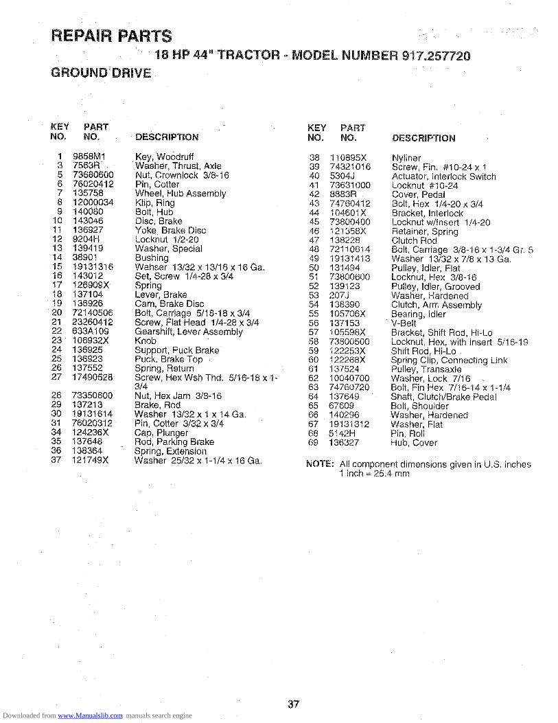
REPAIR PARTS18 HP 44" TRACTOR - MODEL NUMBER 917.257720
GROUND DRIVE
KEY PART KEY PARTNO. NO. DESCRiPTiON NO. NO. DESCRiPTiON
1 9858M1 Key, Woodruff 38 110895X3 7563R Washer, Thrust Axle 39 743210165 73680600 Nut, Crownlock 3/8-16 40 5304J6 76020412 Pin, Cotter 41 736310007 135758 Wheel, Hub Assembly 42 8883R8 12000034 Klip, Ring 43 747604129 140080 Bolt, Hub 44 104601X
10 143046 Disc, Brake 45 7380040011 136927 Yoke, Brake Disc 46 121358X12 9204H Locknut 1/2-20 47 13822813 139419 Washer, Special 48 7211061414 38901 Bushing 49 1913141315 19131316 Wahser 13/32 x 13/16x 16 Ga. 50 13149416 143012 Set, Screw 1/4-28 × 3/4 51 7380060017 126909X Spring 52 13912318 137104 Lever, Brake 53 207J!9 136926 Cam, Brake Disc 54 13839020 72140506 Bolt, Carriage 5/18-18 x 3/4 55 105706X21 23260412 Screw. Flat Head 1/4-28 x 3/4 56 13715322 633A109 Gearshift, Lever Assembly 57 105598X23 106932X Knob 58 7380050024 136925 Support, Puck Brake 59 122253X25 136923 Puck. Brake Top 60 122268X26 137552 Spring, Return 61 13752427 17490528 Screw, Hex Wsh Thd. 5/16-18 x 1- 62 10040700
3/4 63 7476072028 73350600 Nut, Hex Jam 3/8-16 64 13764929 137213 Brake, Rod 65 6760930 19131614 Washer 13/32 x 1 x 14Ga. 66 14029631 76020312 Pin, Cotter 3/32 x 3/4 67 1913131234 124236X Cap, Plunger 68 5!42H35 137648 Rod, Parking Brake 69 13632736 138364 Spring, Extension37 121749X Washer 25/32 x 1-1/4 x 16 Ga.
NylinerScrew, Fin. #10-24 x !Actuator, Interlock SwitchLocknut #10-24Cover, PedalBolt, Hex 1/4-20 x 3/4Bracket, InterlockLocknut w/Insert 1/4-20Retainer, SpringClutch RodBolt, Carriage 3/8-16 x 1-3/4 Gr. 5Washer 13/32 x 7/8 x 13 Ga.Pulley, Idler, FlatLocknut, Hex 3/8-16Pulley, Idler, GroovedWasher, HardenedClutch, Arm AssemblyBearing, IdlerWBeltBracket, Shift Rod, Hi-LoLocknut. Hex, with Insert 5/16-19Shift Rod, Hi-LoSpring Clip, Connecting LinkPulley, TransaxleWasher. Lock 7/16Bolt, Fin Hex 7/16-14 x 1-1/4Shaft, Clutch/Brake PedalBolt, ShoutderWasher, HardenedWasher, FlatPin. RollHub, Cover
NOTE: All component dimensions given in U.S. inches1 inch = 25.4 mm
37Downloaded from www.Manualslib.com manuals search engine

REPAIR PARTS18 HP 44" TRACTOR = MODEL NUMBER 917.257720
STEERING ASSEMBLY
26f
/
24
34
/27
23
22/
31/
/
/
3332
19
27 /6 /
/
/16
5
//
38Downloaded from www.Manualslib.com manuals search engine
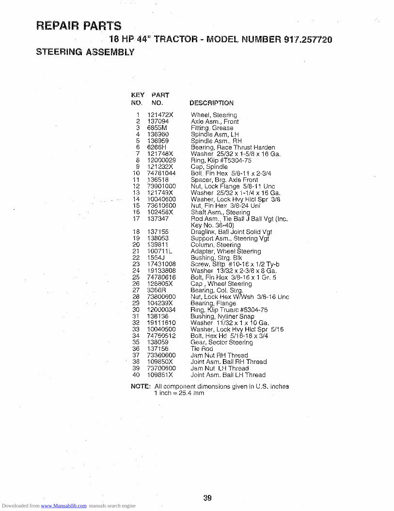
REPAIR PARTS18 HP 44" TRACTOR = MODEL NUMBER 917.257720
STEERING ASSEMBLY
KEY PARTNO. NO. DESCRIPTION
! 121472X2 1370943 6855M4 1369605 1369596 6266H7 121748X8 120000299 121232X
10 7478104411 13651812 7390100013 121749X14 1004060015 7361060016 102458X17 137347
18 13715519 13805320 13981121 100711L22 1554J23 1743100824 1913380825 7478061626 126805X27 3366R28 7380060029 104239X30 1200003431 13813632 1911161033 1004050034 7476051235 13805936 13715637 7336060038 109850X39 7370060040 109851X
Wheel, SteeringAxle Asm., FrontFitting, GreaseSpindle Asm, LHSpindle Asm., RHBearing, Race Thrust HardenWasher 25/32 x 1-5/8 x 16 Ga.Ring, Klip #T5304-75Cap, SpindleBolt, Fin Hex 5/8-11 x 2-3/4Spacer, Brg. Axle FrontNut Lock Flange 5/8-11 UncWasher 25/32 x 1-1/4 x 16 Ga.Washer, Lock Hvy Hlcl Spr 3/8Nut, Fin Hex 3/8-24 UnfShaft Asm,, SteeringRod Asm., Tie Ball J Ball Vgt (Inc.Key No. 36_40)Draglink, Ball Joint Solid VgtSupport Asm., Steering VgtColumn, SteeringAdapter, Wheel SteeringBushing, Strg. BIkScrew, Slftp #10-16 x 1/2 Ty-bWasher 13/32 x 2-3/8 x 8 Ga.Bolt, Fin Hex 3/8-16 x 1 Gr. 5Cap, Wheel SteeringBearing, Col. Strg.Nut, Lock Hex W/Wsh 3/8-16 UncBearing, FlangeRing, Klip Truarc #5304-75Bushing, Nyliner SnapWasher 11/32 x 1 x lOGa.Washer, Lock Hvy Hlcl Spr 5/16Bolt, Hex Hd 5/16-18 x 3/4Gear, Sector SteeringTie RodJam Nut RH ThreadJoint Asm. Ball RH ThreadJam Nut LH ThreadJoint Asm. Ball LH Thread
NOTE: All component dimensions given in U.S. inches1 inch = 25.4 mm
39Downloaded from www.Manualslib.com manuals search engine

'REPA_ PA_'T$
!8 HP 44!' "TRACTORENGIN,E
•" MODEL NUMBER 917.257720
• , ...... 13 32
...............•f
1718
. _ ,S '/
"1:5
28
37
2O
/
/
/i
/
/
3O
i
12 19
43 42 41
4O
9
29
[ SPARK: ARRESTEF_ K_T]
34,
4ODownloaded from www.Manualslib.com manuals search engine

REPAIR
ENGINE
PARTS18 HP 44" TRACTOR = MODEL NUMBER 917.257720
KEY PARTNO. NO.
12
14! 948144110
3 132403004 132803285 1320030O6 1381298 121361X9 138559
10 105432X11 13714012 13690713 13848614 13848715 127334X16 109227X17 106082X18 123549X19 13290300
2O 13343921 17720410
KEY PARTDESCRiPTiON NO. NO. DESCRiPTiON
Engine Kohler 18 Mag Vt 22Muffler Asm Kohler VGT (Inc. Key 23No. 34) 24Elbow Street 3/8 NPT 25Nipple Pipe 3/8NPT X 3 - 1/2 26Elbow STD 90 Degree 3/8 - 18 NPT 27Clamp Tube Double Engine 28Pulley V-Idler 29Stop Keeper Asm VGT 30Bushing 32Clutch Electric 34Pulley Engine VGT Elect Clutch 35Baffle Air LH Koh VGT 36Baffle Air RH Koh VGT 37Tank Fuel W/Sym Vented 38Pad Spacer 39Pad Spacer 40Cap Asm Fuel W/Sym, Vented 41Plug Oil Drain (Order From Engine 42Manufacturer) 43Control ThrottleScrew Hex Thd Cut 1/4 - 20 X 5/8
1386721913261611050600736106003645J1392777834R
105037X17490508177204081004050074570512123487X110506001749062417490652126197X1004070071170768
Control ChokeWasher 13/32 X 1 - 5/8 X 16 GaWasher Ext Tooth 3/8Nut Fin Hex 3/8 - 24 UNFBushingStem Tank FuelFuel LineSpark Arrester KitStrip FoamScrew Thdrol 5/16 - 18 X 1/2Screw Thd Cut 1.4 - 20 x 1/2Washer Lock 5/16Screw Hex 5/16 - 16 UNC X 3/4Clamp HoseLockwasher Ext Tooth 3/8Screw Thdrol 3/8 - 16 X 1 - 1/2 TTScrew Thdrol 3/8 - 16 X 3 - 1/4Washer 1-1/20D X 15/32 ID X .250Washer Lock 7/16Bolt Hex 7/16 - 20 X 4 - 1/4 Ga 5
NOTE: All component dimensions given in U.S. inches1 inch = 25.4 mm
.J
41Downloaded from www.Manualslib.com manuals search engine

REPAIR PARTS18 HP 44" TRACTOR - MODEL NUMBER 917,257720
SEAT ASSEMBLY
J
\\\
54
\\
18
\19 ),
12
8--.._ G__/=°
9_-__ S 8
7_ pj_-9
- 4L"
" - " : - - ""'.-.rJ: - ;-.
/5 "'-.
KEYNO.
123456789
!012t3
PARTNO.
127439140551140675127018X14040773680600t24181X1749050819131614140552121246X121248X
DESCRiPTiON
SeatBracket, Pivot SeatStrap, FenderBolt, Shoulder 5/16o18 x .62Clip, Push InNut, Crownlock 3/8-16 UncSpring, Seat CprsnScrew. Thdrol 5/16-18 X 1/2Washer 13/32 X 1 X 14 Ga.Pan, SeatBracket, Mounting SwitchBushing, Snap
K EY PARTNO. NO.
14 7205041115 12!249X16 123740X17 123976X!8 1917191219 120068X20 124238X21 13988822 73680500
DESCRiPTiON
Bolt, Carriage 1/4-20 X 1-3/8Spacer, SplitSpring, CprsnNut, Lock 1/4 Lge Ftg Gr. 5Washer 17/32 × !-3/16 x 12 Ga.Knob, Seat 1/2-13 UncCap, Spring SeatBolt, Shoulder 5/16-18Nut, Crownlock 5/16-18 Uric
NOTE: All component dimensions gwen in U.S. inches1 inch = 25.4 mm
42
Downloaded from www.Manualslib.com manuals search engine

REPAIR PARTS18 HP 44"
LiFT ASSEMBLY
TRACTOR .. MODEL NUMBER 917.257720
KEYNO.
123456789
!0111213!4151617181920212223
23
4042 43 3
39
41 /42
<
13
_23
\11
23
2
2625
/
//
6
1\
\\
\\
\
7/
//
//
//
/
\ \
12 16
13
2212
20 19"18 15
PARTNO.
!21006X137295121002X120000221929201674780624125631X122365X122364X2876H1380203146R13986714030273800600674A247733506005329J191313165328J747606161272184939M
DESCRIPTION
Rod Asm., LeverShaft Asm., Lift VgtLever Asm., Lift RhEoRing Truarc #5133-87Washer 29/32 x 1-1/4 x 16 Ga,Bolt, Fin Hex 3/8-16 x 1-1/2Grip, Handle FlutedButton, PlungerPlunger, Lever LiftSpring 2-1/8"Link LiftRetainer, SpringArm, Suspension VgtBearingNut, Lock Hex WfWsh 3/8-16 UncSpring Asm., Assist LiftNut, Hex Jam 3/8-16 UnoBracket Spring AssistWasher 13/32 x 13/16 x 16 Ga.Bolt, Adjust Spring AssistBolt, Fin Hex 3/8-16 x 1Link, FrontRetainer, Spring
43
KEY PARTNO. NO. DESCRIPTION
24 73350800 Nut, Jam Hex 1/2-13 Unc25 130171 Trunnion26 73800800 Nut, LockW/Wsh !/2-13 Uric27 12000037 Ring, Ktip #T5304-3728 19151216 Washer 15/32x3/4x16Ga.29 110810X Trunnion Dp Stop Dbl Thds Pit30 1!0807X Nut. Special31 19131016 Washer 13/32x5/8x 16 Ga.32 137150 Spring, Compression Inf Hgt33 76020308 Pin, Cotter 3/32 x !/234 137167 Rod, Adj Lift35 138057 Knob, Inf 3/8-16 Unc36 17490612 Screw, Thdrol 3/8-16 x 3/437 120529X Washer, Nylon38 !23933X505 Pointer, Pnt Height Indicator39 123935X Plug, Hole40 74780516 Bolt, Fin Hex 5/16-1 8 x 141 10040500 Washer, Lock Hvy HIcl Spr 5/1642 19112410 Washer 11i32xl-1/2x10Ga.43 123934X Scale, Indicator Height
NOTE: All component dimensions given in U.S. inches1 inch = 25,4 mm
Downloaded from www.Manualslib.com manuals search engine

REPAIR PARTS18 HP 44" TRACTOR - MODEL NUMBER 917.257720
44" MOWER DECK
6O5960
58 \57
55
I
/64
4553
48 38 29
3O
32
47
2
24
546 \
10
42\26 18
17
/23
22
44Downloaded from www.Manualslib.com manuals search engine

REPAIR PARTS!8 HP 44" TRACTOR .-MODEL NUMBER 9! 7,257720
44" MOWER DECK
KEYNO.
123456789
10111213
14151617181920212223242526272829303132
[qq 1- ec, e, oloPART KEY PARTNO. DESCRIPTION NO. NO.
136471738O050072110506763tj1384574939M13083285085710030600129962130652129895137553
137152110485X136929106735X19111016105304Xt23713X137607110452X109785X13632'119111216721106141913131613282373800600133776137266129861
Deck Asm., Mower 44" VentedLocknut, Hex W/Ins 5/16-18 UncBolt, Carriage 5/16-18 x 3/4Runner, Mower LHBracket Asm., Sway BarRetainer, SpringArm Suspension, RearBolt 3/8-24 x 1.25 Gr. 8 PatchedWasher, Lock Hvy 3/8 UnplatedWasher, Hard Blade Mower VentedBladeBearing, Ball #6204 (Mandrel)Shaft Asm., W/Lower Brg (includesKey No. 12)Housing, Mandrel 44" VentBearing, Ball MandrelStripper, Mower VentedRod, HingeWasher 11/32 x 5/8 x 16 Ga,Cap, SleeveSpring, Torsion DeflectorBracket, DeflectorNut, PushShield, Deflector MowerRunner, RHWasher 11/32 x 3/4 x 16 Ga.Bolt, Carriage 3/8-16 x 1-3/4 Gr. 5Washer 13/32 x i3/16 x 16 Ga.Spacer, Spring Stop idlerNut, Lock Hex W_sh 3/8-16 UncBolt 5/16-18 x 1,25Nut, Fig Top Lock Cntr 9/16Pulley, Mandrel
33 12996334 7214061035 7211061636 7211060837 13716638 13755439 13149440 13657242 7214050643 13646044 122052X45 7368060046 7476062847 13720048 13772949 13657450 13727251 13727352 13924553 13778954 13126455 1312905613868757 13657758 13395759 13764460 1390316t 13657362 13394363 7211061264 1912141467 73930600
DESCRIPTION
Washer, Spacer Mower VentedBolt, Carriage 3/8-16 x 1-1/4Bolt, Carriage 3/8-!6 x 2Bolt, Carriage 3/8-16 x 1 Gr. 5Stiffener, Arm IdlerKeeper, Belt IdlerPulley, Idler FlatPulley, DrivenBolt, Carriage 5/16-18 Unc x 3/4Arm, idler SecondarySpacer, RetainerNut, Crownlock 3/8-16 UricBolt, Fin Hex 3/8-16 Uric x 1-3/4Cover, Mandrel RHScrew, Thd RoW 1/4-20 x 5/8Cover, Mandrel LHArm, Idler PrimarySpring, SecondaryPulley, idler V GrooveShield, IdlerV-Belt, Mower PrimaryV-Bek, Mower SecondarySpring, PrimaryBar Asm., Wheel GaugeWheel, GaugeBolt, ShoulderPin, ClevisBracket, Wheel GaugeWasher HardenedBolt Cardage 3/8-16 x 1-1/2Washer 3/8 x 3/4 x 14GaNut, Centerlock 3/8-16
NOTE: All component dimensions given in U.S. inches1 inch = 25.4 mm
45Downloaded from www.Manualslib.com manuals search engine

REPAIR PARTS18 HP 44" TRACTOR ° MODEL NUMBER 917.257720
TRANSAXLE
7O
73
86 _85
88_'__87
_94
15
7
,_.----9 7
48
Downloaded from www.Manualslib.com manuals search engine

REPAIR PARTS18 HP 44" TRACTOR =
TRANSAXLE
MODEL NUMBER 917.257720
KEY PARTNO, NO. DESCRiPTiON
1 4197R2 120000343 4199R4 4216R5 4215R6 4217R7 6256H8 74020652
91011121314!516171819202122232425262728293031
32333435363739
4O414546495051
7392M1372614985R6266H4212R1371256276H633A638118M8740H1122238X4218R6252H17810H6262H7393R992R11391114986R122254X6269H5855H139538
6277H4225R7396H4198R4200R7395H139536
13320400175805206271H130602004895H4222R1529R
Axle ShaftRetaining RingFinal Drive GearDifferential GearDifferential PinionDifferential CarrierAxle Thrust WasherBolt, Hex Head 3/8-24 x 3-1/4(1" Thread Length)Steel BallSpring Shift Fork DetentShift Fork. High-Low RangeThrust Bearing Race4th Reduction PinionShaft, BrakeSnap Ring, Crescent TypeHigh-Low Range GearsNeedle BearingSintered iron BearingShift Fork Shaft, High-Low RangeDifferential Pinion SpacerDifferential Pinion BushingGripco Centerlock Nut 3/8-24Shift Fork, R.H.Oil Sea!Sintered Iron BearingShift Fork ShaftShift Fork, L.H.Shift Shaft, High-Low RangeOil SealPressure Relief ValveGearcase, Reverse Idler Shaft andBearings, R.H. (includes Key No.'s17,18, 25, 33, 50, 63, 77 and 82)Dowel PinNeedle BearingThrust Bearing Race4th Reduction Gear Shaft4th Reduction Gear SpacerThrust Bearing RaceGearcase and Bearings, L.H.(Includes Key Numbers 18, 25, 49,50 (2), 51 and 52)Pipe Plug 1/2-14 N.P.T.Bolt, Hex 5/16-18 UNC x 1-1/4Oil SealPipe Plug 1/4-18 N.P.T.Needle BearingNeedle BearingNeedle Bearing
KEY PARTNO. NO. DESCRiPTiON
52 8119M53 4220R54 4209R55 4213R56 4442R57 4195R58 42t4R59 4194R60 7528R61 4208R62 4207R63 7398H64 4203R
65 4204R66 2898J67 1200003368 4205R69 4206R70 1370H71 633A69
72 13912073 4201R74 1200000875 1153R77 6803J79 1167R80 7336070081 6270H82 13698484 5384J85 2978J86 633A8587 8739H!88 4924H89 1915151690 110542X91 1918151192 75J93 6274H94 7602041295 1004050096 7476051497 633A10998 139535
Needle BearingThrust Bearing Race3rd Reduction Pinion, Low4th Reduction Gear3rd Reduction Pinion Spacer2nd Reduction Gear ShaftFina! Drive Pinion1st Reduction Gear Shaft1st Reduction Shaft Spacer3rd Reduction Pinion Hlgh2nd Reduction GearNeedle BearingLow Speed Gear and 2ndReduction Pinion ClusterReverse GearKey, Hi-Pro !/8 x 17/32Klip RingIntermediate Speed GearHigh Speed GearThrust Bearing RaceIntermediate and High SpeedCluster PinionsInput ShaftLow Speed PinionE-RingReverse Idler GearNeedle BearingSealing WasherNut, Hex, ,Jam 7/16-20Oil SealReverse Idler ShaftGearshift Lever, BentGearshift CapGearshift Ball Cover and PinShift Lever Guide Ball, KeyedSpringWasher 15/32 x 15/16 x 16 GaugeShift Mechanism SeatWasher 9/16 x !5/16 x 12 GaugeGearshift Gate and ReinforcementShift Ball Cover GasketCotter Pin 1/8 x 3/4Washer, Lock 5/16Bolt, Hex Head 5/16-18 UNC x 7/8Gearshift Lever AssemblyTransaxle Assembly(Less Brake Drum and Shift Lever)
NOTE: All component dimensions given in U.S. inches1 inch = 25.4 mm
47
Downloaded from www.Manualslib.com manuals search engine

REPAIR PARTS18 HP 44" TRACTOR - MODEL NUMBER 917.257720
KOHLER ENGINE - MODEL NUMBER MV18S, TYPE NUMBER 58560
/1/
2 m
_3
Jo 5
--8
BAFFLES AND SHROUD
/8 /
7
/
5
,%/
4
BREATHER AND VENT
11/lilt I_+ -+ +++++-
48
Downloaded from www.Manualslib.com manuals search engine

REPAIR PARTS18 HP 44" TRACTOR = MODEL NUMBER 917.257720
KOHLER ENGINE = MODEL NUMBER MV18S, TYPE NUMBER 58580
AiR INTAKE BAFFLES & SHROUD
KEY PART DESCRIPTION KEY PARTNO. NO. NO. NO,
!2
X-276-7 Wing Nut t/4-20 1 52 063 4152 755 83 Kit, Cover and Tube 2 52 313 05
(Includes Key Numbers 3 and 4) 3 52 063 42Cover, Air Cleaner 4 X-67-833 52 096 35
4 52 123 2!5 2310326 52 082 047 45 083 018 45 083 029 237423
!0 X-67-98
11 52 201 0612 27709313 52 054, 3914 X-25-7915 X-50-37
16 X-50-57
17 X-22-9
Tube, Air IntakeSea!, Element CoverCover, Air Cleaner ElementPre-CleanerElementSeal, Air Cleaner CoverScrew, Hex Washer Head#10-32 x 9/16 (4)Base, Air CleanerGasket, Air Cleaner (2)Elbow, Air IntakeWasher, Plain #10Screw, Slotted Pan Head#10-32 x 2-1/4Screw, Slotted Pan Head#10-32 x 1_3/4 (2)Washer, Lock, Interna Tooth#10 (2)Gasket, Air Cleaner Elbow18 25 04! 06
NOT ILLUSTRATED- - 25 113 15 Decal, Air Cleaner-- 5211330 Decal
DESCRIPTION
5 52 755 70
6 52 217 017 52 468 168 52 086 119 52 124 23
Baffle, #2 Cylinder HeadGrommet (2)Baffle, Fuel PumpScrew, Hex Washer Head1/4_20 x 7/16 (14)Kit, Blower Housing('Includes Key Numbers 6 thru 8)Support, Upper HousingWasher, Flat (2)Screw 1/4_20 x 5/8 (6)Baffle, #1 Cylinder Head
NOT ILLUSTRATED- - 52 113 46 Decal, Horsepower (3)
BREATHER & VENT
KEY PARTNO, NO,
DESCRiPTiON
1 X=81-12 X-25-123 52 096 184 52 055 015 X-352-39
6 52 326 127 52 096 088 52 032 049 52 462 01
10 52 096 2211 275220
Nut, Hex !/4-20 (2)Washer, Plain 1/4 (2)Cover #2 Cylinder ValveGasket. Cover (3)Stud, #2 Cylinder Valve Cover1/4-20 x 2-1/4Hose, BreatherCover, #1 Upper Cylinder ValveSeal, BreatherValve, UmbrellaCover, #! Lower Cylinder ValveStud, #1 Cylinder Valve Cover1/4-20 x 3q/4
NOTE: All component dimensions given in U.S° inches1 inch = 25.4 mm
49
Downloaded from www.Manualslib.com manuals search engine

REPAIR PARTS18 HP 44" TRACTOR - MODEL NUMBER 917,257720
KOHLER ENGINE - MODEL NUMBER MV18S, TYPE NUMBER 58560
3
17/ 18
' /
5
5O
Downloaded from www.Manualslib.com manuals search engine

REPAIR PARTS18 HP 44" TRACTOR = MODEL NUMBER 9! 7.257720
KOHLER ENGINE = MODEL NUMBER MV18S, TYPE NUMBER 58560
CRANKCASE CARBURETOR
KEY PART DESCRiPTiON KEY PART DESCRIPTIONNO. NO. NO. NO,
1 X-82-2 Nut, Hex 5/16-18 (12) 1 52 041 092 52 468 12 Washer, Flat 5/16 (12) 2 52 755 913 82 755 16 Kit, #1 Cylinder Barrel
3 52 164 154 52 016 05 4 X-21=15 52 031 01 5 X-6-296 52 316 06 6 X-75-237 52 755 508 52 072 12 7 235778
8 X-67-979 25 086 12
10 X-269-4311 52 078 0512 52 030 10
52 030 1152 030 12
13 25 086 10
14 25 086 13
!5 52 141 0216 52 139 0817 25 086 11
18 52 032 1019 82 755 17
0 - = -
(Includes Key Numbers 4 thru 6)Valve, ExhaustInsert, Valve Seat (2)Guide, Valve (2)Kit, Oil ReliefStep Stud 5/16-18 x 3/4,3/8-16 x 5/8, 2" Long (12)Screw, Hex Flange 5/16-18 x 2 (2)Ring, RetainingShaft, GovernorBearing, Sleeve, Standard (2)Bearing, Sleeve .010" (2)Bearing, Sleeve .020" (2)Screw, Hex Flange5/16-18 x 1-1/2 (3)Screw, Hex Flange3/8-16 x 3-5/8 (2)O-RingPlugScrew, Hex Flange5/16-18 x 3-1/2 (8)Seal, Oil, FrontKit. #2 Cylinder Barrel(Includes Key Numbers 4 thru 6)Crankcase (Service with ShortBlock, Part Number 82 522 30)
9 41 072 1910 52 063 4011 25 155 0212 52 853 25
13 27103014 52 053 54
15 25 041 0616 X-77-217 23286718 X-67-62
19 25 086 2720 25 146 0321 52 144 2422 25 368 0123 25 089 0224 25 086 2625 25 089 0426 25 368 0327 25 089 0228 52 090 1329 25 089 0330 25 194 0131 25 146 0232 25 041 0433 25 757 0934 25 104 0135 25 041 0336 25 100 05
Gasket, Intake (2)Kit, Manifold(includes Key Numbers 3 thru 8)Manifold, intakeWasher, Lock 5/16 (4)Screw, Hex Cap 5/16-18 x 2 (4)Plug, Hex, Countersunk1/8 N.P.T.F.Clamp, Cable (2)Screw, Hex Washer Head#10-24 x 3/8 (2)Stud 5/16-18 x 1 (2)Baffle, CarburetorConnector, HoseKit, Carburetor with Gasket(Includes Key Numbers 12 thru 14)Gasket, Carburetor (2)Carburetor Assembly (informationOnly - Not Available Separately)(includes Key Numbers 18 thru 35)Gasket, Air CleanerNut 5/16 (2)Strap, LiftingScrew, Hex Washer Head1/4-20 x 3/4Screw, Throttle and Choke Plate (4)Plate, ChokeShaft, Throttle with Lever and SeaNeedle, Idle Fuel AdjustSpring, Idle, FuelScrew, Idle Speed AdjustSpring, Idle SpeedNeedle, Main FuelSpring, Main FuelLever, ChokeSpring, Choke, FrictionBall, Choke, FrictionPlate, ThrottleGasket, BowlKit, FloatBowl, Fue!Gasket, Bowl Retainer ScrewScrew, Bowl Retainer
NOT ILLUSTRATED- - 25 757 11 Kit, Carburetor Repair- - 25 757 23 Kit, Bowl Baffle
NOTE: All component dimensions given in U.S. inches1 inch = 25.4 mm
51Downloaded from www.Manualslib.com manuals search engine
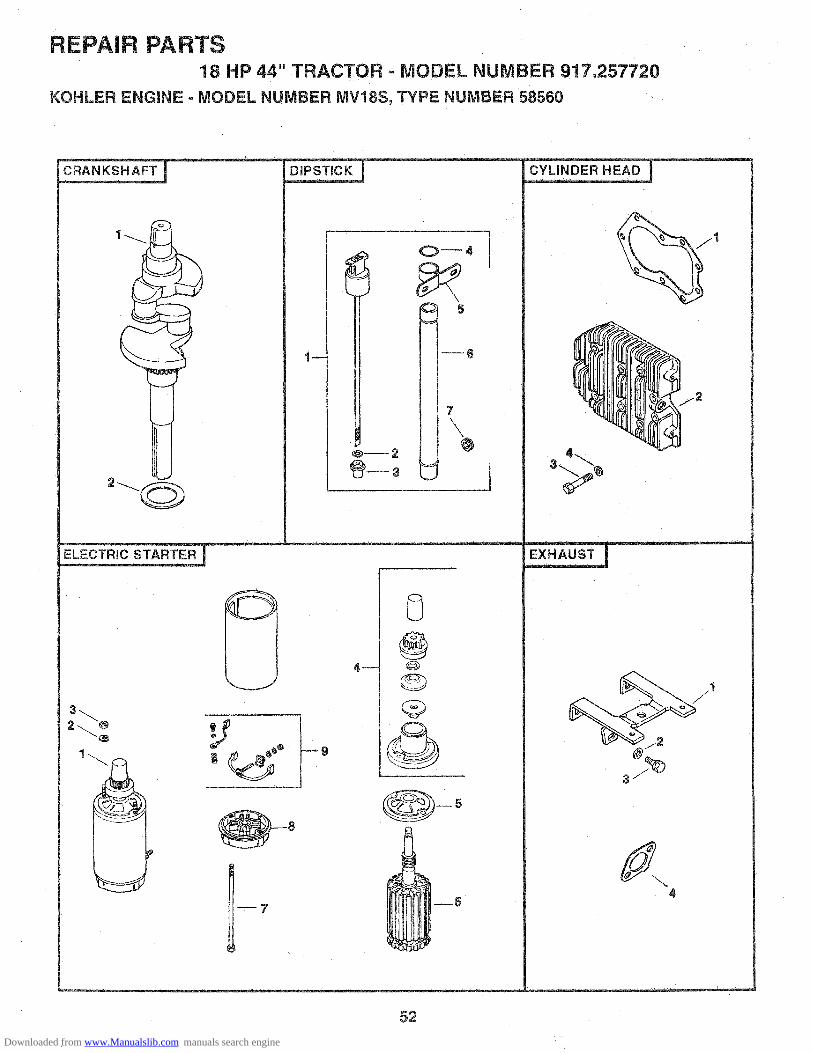
REPAIR PARTS18 HP 44" TRACTOR o MODEL NUMBER 917.257720
KOHLER ENGINE - MODEL NUMBER MV18S, TYPE NUMBER 58560
O_4
6
7
1
J
2
1
:14_
8®@-D
Q@
--6
52
Downloaded from www.Manualslib.com manuals search engine

REPAIR PARTS18HP 44" TRACTOR .. MODEL NUMBER 917.257720
KOHLER ENGINE ° MODEL NUMBER MV18S, TYPE NUMBER 58560
CRANKSHAFT ELECTRIC STARTER
KEY PART DESCRiPTiON KEY PARTNO. NO. NO, NO.
1 52 014 932 52 468 03
52 468 0452 468 05
DiPSTiCK
KEY PARTNO. NO.
1 52 038 14
2 X-25-443 52 032 144 41 153 015 52 126 116 52 123 207 47 139 01
CYLINDER HEAD
KEY PARTNO, NO,
CrankshaftWasher, Thrust .119/.122 (A.R.)Washer, Thrust .128/.131Washer, Th rust .137/. 140 (A. R,)
DESCRiPTiON
Dipstick AssemblyIncludes Key Numbers 2 and 3)asher, Plain 5/16
Seal, RubberQ-RingBracket, Oil Tube SupportTube, Oil Fill 11-7/8Plug, Hex, Countersunk3/4 N.P.T.F.
DESCRiPTiON
Gasket, Head (2)Cylinder Head (2)Washer. Plain 5/16 (18)Screw, Hex Head5/16-18 x 1-1/2 (18)
1 52 04.1 202 52 015 083 2205344 41 086 02
DESCRIPTmON
1 52 098 12
2 X-20-13 X-81-14 82 755 265 52 081 076 52 170 057 52 211 018 52 227 109 82 755 28
Starter Assembly(Includes Key Numbers 4 thru 9)Washer, Lock 1/4 (2)Nut, Hex 1/4-20 (2)Kit, DriveCap, Drive EndArmatureBolt, Thru (2)Cap, Commutator EndKit, Brush
NOT ILLUSTRATED- - 25 450 03 Tag, Caution
EXHAUST
KEY PARTNO. NO,
DESCRiPTiON
1234
52 126 12X-25-7252 086 1152 041 14
BracketWasher, Plain (3)Screw 1/4-20 x 5/8 (3)Gasket, Exhaust (2)
NOTE: All component dimensions given in U.S. inches1 inch = 25.4 mm
53
Downloaded from www.Manualslib.com manuals search engine

REPAIR PARTS18 HP 44" TRACTOR- MODEL ,NUMBER 917o257720
KOHLER ENGINE oMODEL NUMBER MV18S, TYPE NUMBER 58560
iGNiTiON
4
11 _ -_14
10 --_]
9 8
FUEL PUMP
\s \ 1
!o C/ \g
6_3
8
54
Downloaded from www.Manualslib.com manuals search engine

REPAIR PARTS18 HP 44" TRACTOR - MODEL NUMBER 917.257720
KOHLER ENGINE - MODEL NUMBER MVlSS, TYPE NUMBER 58560
FLYWHEEL FUEL PUMP
KEY PART DESCRIPTION KEY PART DESCRIPTIONNO. NO. NO. NO.
1 25 162 01 Screen. Grass2 25 086 21 Screw Hex Washer Head
1/4-20 x 5/8 (4)3 25 112 04 Spacer (4)4 2515701 Fan5 25 086 24 Screw, Hex Machine 3/8-24 x 1-1/46 52 468 15 Washer_ Plain7 X-286-17 Key, Square 3/16 x 7/88 52 025 36 Flywheel
GOVERNOR
KEY PART DESCRIPTIONNO. NO.
1 2313552 X-25-123 2370224 A-235743-S5 52 O78 046 X_25-1027 X-269-288 X-25-729 52 090 23
10 27734111 52 158 0712 25 086 15
13 52 089 0714 X-81-115 X-25-6316 52 186 0917 52 211 04
18 25 141 0319 25 158 0820 52 079 0721 52 O79 0622 52 090 1423 52 089 0824 25 086 21
25 X-67-97
26 23577827 25 431 0128 X-70-329 52 086 05
Pin, Governor StopWasher, Plain 1/4Washer, ThrustKit, Governor GearShaft, Governor CrossWasher, Plain 1/4 (2)Retainer, GovernorWasher, Plain 1!4 (2)Lever_ Speed ControlWasher, TensionBushing, Throttle Control LeverScrew. Hex Washer Head1/4-20 x 1Spring, GovernorNut, Hex 1/4-20Washer, Plain 1/4Arm, GovernorScrew, Round Head, Square Neck1/4-20 x 1Ring, Retaining (4)Bushing, Linkage Retaining (4)Linkage, GovernorLinkage, ThrottleLever. ThrottleSpring, TorsionScrew, Hex Washer Head1/4-20 x 5/8Screw. Hex Washer Head#10-24 x 3/8 (3)Clamp, Cable (3)Bushing, Speed Control LeverNut. Hex #10-32Screw, Hex Head #10-32 x 7/8
1 47 086 08
2 52 559 01
3 X-380-14 X-25-635 25 041 096 25 155 027 X-426-98 52 353 189 25 050 03
10 15 353 04
Screw, Pozidriv, Truss Head1/4-20 x 5/8 (2)Pump, Fuel Assembly(Includes Key Numbers 3 thru 6)Connector, StraightWasher, Plain 1/4 (2)Gasket Fuel PumpConnector, HoseClamp, Hose (4)Line, Fuel, 8"Filter, FuelLine, Fuel, 11-1/2"
iGNiTION
KEY PARTNO. NO.
DESCRiPTiON
25 755 03
2 X-132-53 2366024 2378785 X-67-516 2102817 X-67-64
89
10111213
1415
41 155 0322029752 3!3 0252 132 0252 126 0825 086 15
52 584 0225 086 16
Kit, Rectifier-Regulator(Includes Key Number 2)Screw, Hex Cap 1/4-20 x 5/8 (2)Connector, 3 ContactKit, Stator (Includes Key Number 5)Screw, Hex Cap #10-24 x 3/4 (2)Clip (2)Screw, Hex Washer Head#10-32 x 7/16Connector, 2 ContactGrommet, RubberGrommetSpark Plug (2)Bracket, ModuleScrew, Hex Washer Head!/4-20 x 1 (2)Module, IgnitionScrew, Hex Washer Head1/4-20 x 7/8 (2)
NOT ILLUSTRATED47 518 33 Lead, Violet, Rectifier-Regulator
(11", 14 Gauge, Uninsulated PushOn Tab Terminals)
52 518 !9 Lead, White, Module To Connector(19-1/2", 14 Gauge, Insulated PushOn Tab, Uninsulated Push On TabTerminals)
NOTE: All component dimensions given in U.S, inches1 inch = 25.4 mm
55
Downloaded from www.Manualslib.com manuals search engine

REPAIR PARTS18 HP 44" TRACTOR - MODEL NUMBER 917.257720
KOHLER ENGINE = MODEL NUMBER MV18S, TYPE NUMBER 58560
OiL PAN _ 2
--3
J
CAMSHAFT AND VALVES
2
6
OiL FILTER
r__%\°
L____T_____2
__2
7_ -6
4
56
Downloaded from www.Manualslib.com manuals search engine

REPAIR PARTS18 HP 44" TRACTOR - MODEL NUMBER 917.257720
KOHLER ENGINE - MODEL NUMBER MV18S_ TYPE NUMBER 58560
OIL PAN
KEY PART DESCRIPTIONNO. NO.
1 X-67-64
2 52 050 033 52 199 144 X-702-145 52 054 076 X-75-38
7 X-75o108 52 086 12
9 52 032 10
OiL FILTER
KEY PARTNO. NO.
1 52 050 022 82 755 23
3 X_55-15
4 X-75-23
5 52 041 16
PISTON & ROD
KEY PARTNO. NO.
1 52 067 6752 067 68
2 52 874 1152 874 1252 874 !352 874 !452 874 15
3 2300044 52 108 09
52 108 10 Ring Set o010" (2)52 108 11 Ring Set .020" (2)52 108 12 Ring Set .030" (2)
LOW OIL PRESSURE SWITCH
Screw, Hex Washer Head KEY PART#10-32 x 7/16 (2) NO. NO.Filter, Oil PickupOil Pan (Includes Key #4 thru 6) 1 X-75o23Plug, Cup 1-1/16Elbow, StreetPlug, Hex, Countersunk1/4 N.P.T.F.Plug, Square Head 3/8 N,P.T.F. (2) KEY PARTScrew, Hex Washer Head NO, NO.5/16-18 x 1-1/4 (9)Seal, Oil, Rear
DESCRIPTION
OIl FilterKit, Oil Filter Adaptor(Includes Key Numbers 3 thru 5)Screw, Hex Socket Head5/16-18 x !-1/4 (2)Plug, Hex, Countersunkt/8 NP.T.F.Gasket, Oil Filter
DESCRIPTION
Connecting Rod, Standard (2)Connecting Rod ,010" (2)Piston with Ring Set, Standard (2)Piston with Ring Set .003" (2)Piston with Ring Set .010" (2)Piston with Ring Set .020" (2)Piston with Ring Set .030" (2)Retainer, Piston Pin (4)Ring Set, Standard and .003" (2)
DESCRIPTION
Plug, Pipe 1/8 N.P.T.F.
CAMSHAFT & VALVES
DESCRIPTION
1 52 012 092 52 019 033 41 755 104 52 413 015 25 089 016 52 016 057 52 0!7 088 52 032 139 230011
CamshaftTappet (4)Kit, Retainer (4)Rotator, Exhaust Valve (2)Spring, Valve (4)Valve, Exhaust (2)Valve, Intake (2)Seal, Intake Valve Stem (2)Retainer, intake Valve (2)
OiL PUMP
KEY PARTNO. NO.
DESCRIPTION
1 X-280-252 52 144 053 52 422 01
4 52 043 055 52 393 096 52 096 037 X-67-64
Pin, RollShaft, Oil PumpSpacer, Shim(As Required, Maximum of 2)Gear, Oil PumpRotor SetCover, Oil PumpScrew, Hex Washer Head#10-32 x 7/16 (4)
NOT ILLUSTRATED
- - 82 522 30- _ 52 755 94
Short BlockGasket Set
RPM Settings: Low Speed: 1150-1650High Speed: 3200-3400
NOTE: All component dimensions given in U.S. inches1 inch = 25.4 mm
57
Downloaded from www.Manualslib.com manuals search engine

SUGGESTED GUIDE FOR SiGHTiNG SLOPES FOR SAFE OPERATION
SIGHTINGGUIDE
_OUT 0"-
ONLY RIDE UP AND DOWN HILL,NOT ACROSS HiLL
SIGHT AND HOLD THiS LEVEL WiTHSKY LiNE OR TREE=
ilili_F='-_ Operate yourTroa---------v---ctor- up and down the face of slopes (not '!iii| ,_ greater than 15 ), never across the face. Make turns gradu-il _ ally to prevent tipping or loss of control. Exercise extreme_iigi caution when changing direction on slopes.
Downloaded from www.Manualslib.com manuals search engine

A AL
MODEL NO.917.257720
IF YOU NEEDREPAIR SERVICE
OR PARTS:
FOR REPAIR SERVICE, CALLTHIS TOLL FREE NUMBER:
1-800-4-REPAIR(!-800-473-7247)
FOR REPLACEMENT PARTSINFORMATION AND
ORDERING, CALL THISTOLL FREE NUMBER:
1-800-FON-PART(1-80_66-7278)
®
18.0 HP ICELECTRIC START44" MOWER6 SPEED TRANS_LEGARDEN TRA CTOR
Each tractor has its own model number. Each engine hasits own model number.
The model number for your tractor will be found on themodel plate located under the seat.
The model number for your engine wil! be found on theblower housing of the engine.
All parts listed herein may be ordered from any Sears,Roebuck and Co. Service Center/Department and most Re-tail Stores.
WHEN ORDERING REPAIR PARTS, ALWAYS GIVE THEFOLLOWING iNFORMATiON:
,, PRODUCT- TRACTOR
', MODEL NUMBER - 917.257720
,, ENGINE MODEL NO. - MV18S-58556
®PART NUMBER
,, PART DESCRIPTION
Your Sears merchandise has added value when youconsider Sears has service units nationwide staffed withSears trained technicians.., professional techniciansspecifically trained to insure that we meet our pledge toyou, we service what we sell.
140330 Rev, 1 3.04,94 Printed in U.S.A.
Downloaded from www.Manualslib.com manuals search engine


