Embed Size (px)
Citation preview

Crafted With Purpose TM
Batch Bicycles8889 Gander Creek Dr.
Dayton, OH 45342
833.789.8899batchbicycles.com
PLEASE VISIT YOUR AUTHORIZED BATCH RETAILER FOR
SERVICE AND QUESTIONS.
Crafted With Purpose TM
© Batch Bicycles Ltd 2018IBD-Cruiser EN 08-01-18 m0521
OWNER’S MANUALfor Cruiser Bikes
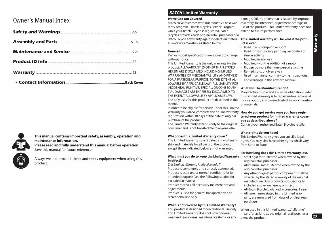
Owner’s Manual Index
Safety and Warnings ...........................................................................................2-5
Assembly and Parts ..............................................................................................6-15
Maintenance and Service ............................................................................ 16-21
Product ID Info .............................................................................................................22
Warranty .............................................................................................................................23
• Contact Information .............................................................Back Cover
This manual contains important safety, assembly, operation and
maintenance information.
Please read and fully understand this manual before operation.
Save this manual for future reference.
Always wear approved helmet and safety equipment when using this product.
23
BATCH Limited Warranty
We’ve Got You Covered
Batch Bicycles comes with our industry’s best war-ranty program – Batch Bicycles Service Program. Once your Batch Bicycle is registered, Batch Bicycles provides each original retail purchaser of a Batch Bicycle a warranty against defects in materi-als and workmanship, as stated below:
General:
Part or model specifi cations are subject to change without notice.This Limited Warranty is the only warranty for the product. ALL WARRANTIES OTHER THAN STATED HEREIN ARE DISCLAIMED INCLUDING IMPLIED WARRANTIES OF MERCHANTABILITY AND FITNESS FOR A PARTICULAR PURPOSE, TO THE EXTENT AL-LOWABLE BY APPLICABLE LAW. ALL LIABILITY FOR INCIDENTAL, PUNITIVE, SPECIAL, OR CONSEQUEN-TIAL DAMAGES ARE EXPRESSLY DISCLAIMED, TO THE EXTENT ALLOWABLE BY APPLICABLE LAW. The only uses for this product are described in this manual. In order to be eligible for service under this Limited Warranty you MUST complete the on-line warranty registration within 30 days of the date of original purchase of the product.The Limited Warranty extends only to the original consumer and is not transferable to anyone else.
What does this Limited Warranty cover?
This Limited Warranty covers defects in workman-ship and materials for all parts of the product except those indicated below as not warranted.
What must you do to keep the Limited Warranty
in eff ect?
This Limited Warranty is eff ective only if:Product is completely and correctly assembled.Product is used under normal conditions for its intended purpose (see the following section for excluded activities).Product receives all necessary maintenance and adjustments.Product is used for general transportation and recreational use only.
What is not covered by this Limited Warranty?
This product is designed for recreational use only. This Limited Warranty does not cover normal wear and tear, normal maintenance items, or any
damage, failure, or loss that is caused by improper assembly, maintenance, adjustment, storage, or use of the product. This limited warranty does not extend to future performance.
This Limited Warranty will be void if the prod-
uct is ever:
• Used in any competitive sport• Used for stunt riding, jumping, aerobatics or
similar activity• Modifi ed in any way• Modifi ed with the addition of a motor• Ridden by more than one person at a time• Rented, sold, or given away• Used in a manner contrary to the instructions
and warnings in this Owner’s Manual
What will The Manufacturer do?
Manufacturer’s sole and exclusive obligation under this Limited Warranty is to repair and/or replace, at its sole option, any covered defect in workmanship or materials.
How do you get service once you have regis-
tered your product for limited warranty cover-
age as described above?
Contact your authorized Batch Bicycles retailer.
What rights do you have?
This Limited Warranty gives you specifi c legal rights. You may also have other rights which vary from State to State.
For how long does this Limited Warranty last?
• Steel rigid fork: Lifetime when owned by the original retail purchaser.
• Aluminum Frame: Lifetime when owned by the original retail purchaser.
• Any other original part or component shall be covered by the stated warranty of the original manufacturer. Any products not specifi cally included above are hereby omitted.
• All Batch Bicycle parts and accessories: 1 year• All time frames stated in this Limited War-
ranty are measured from date of original retail purchase.
When used in this Limited Warranty, “Lifetime” means for as long as the original retail purchaser owns the product.
Wa
rra
nty
22
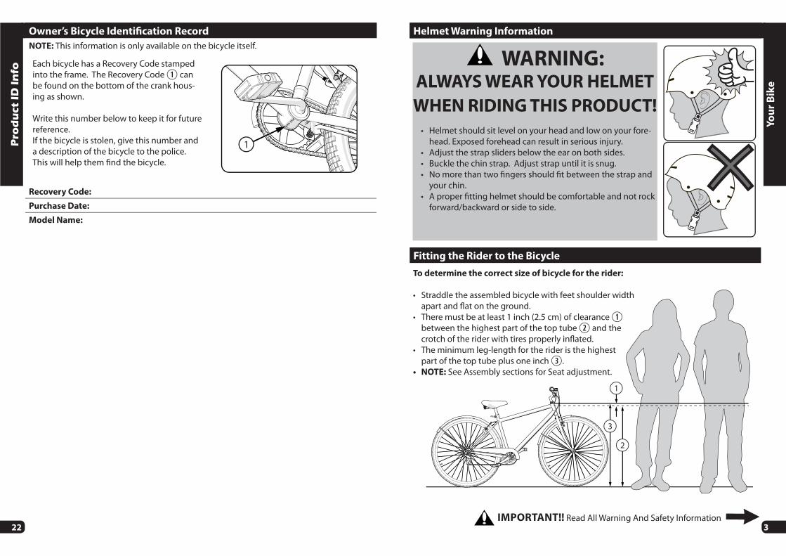
Owner’s Bicycle Identifi cation Record
NOTE: This information is only available on the bicycle itself.
Each bicycle has a Recovery Code stamped into the frame. The Recovery Code can be found on the bottom of the crank hous-ing as shown.
Write this number below to keep it for future reference.If the bicycle is stolen, give this number and a description of the bicycle to the police. This will help them fi nd the bicycle.
1
Recovery Code:
Purchase Date:
Model Name:
Pro
du
ct I
D I
nfo
3
3
1
2
To determine the correct size of bicycle for the rider:
• Straddle the assembled bicycle with feet shoulder width apart and fl at on the ground.
• There must be at least 1 inch (2.5 cm) of clearance between the highest part of the top tube and the crotch of the rider with tires properly infl ated.
• The minimum leg-length for the rider is the highest part of the top tube plus one inch .
• NOTE: See Assembly sections for Seat adjustment.
Fitting the Rider to the Bicycle
Yo
ur
Bik
e
IMPORTANT!! Read All Warning And Safety Information
Helmet Warning Information
WARNING:ALWAYS WEAR YOUR HELMET
WHEN RIDING THIS PRODUCT!
• Helmet should sit level on your head and low on your fore-head. Exposed forehead can result in serious injury.
• Adjust the strap sliders below the ear on both sides.• Buckle the chin strap. Adjust strap until it is snug.• No more than two fi ngers should fi t between the strap and
your chin.• A proper fi tting helmet should be comfortable and not rock
forward/backward or side to side.
4
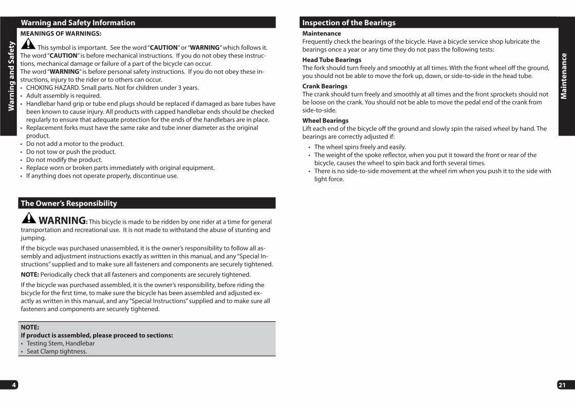
Warning and Safety Information
The Owner’s Responsibility
WARNING: This bicycle is made to be ridden by one rider at a time for general transportation and recreational use. It is not made to withstand the abuse of stunting and jumping.
If the bicycle was purchased unassembled, it is the owner’s responsibility to follow all as-sembly and adjustment instructions exactly as written in this manual, and any “Special In-structions” supplied and to make sure all fasteners and components are securely tightened.
NOTE: Periodically check that all fasteners and components are securely tightened.
If the bicycle was purchased assembled, it is the owner’s responsibility, before riding the bicycle for the fi rst time, to make sure the bicycle has been assembled and adjusted ex-actly as written in this manual, and any “Special Instructions” supplied and to make sure all fasteners and components are securely tightened.
NOTE:
If product is assembled, please proceed to sections:
• Testing Stem, Handlebar• Seat Clamp tightness.
MEANINGS OF WARNINGS:
This symbol is important. See the word “CAUTION” or “WARNING” which follows it.The word “CAUTION” is before mechanical instructions. If you do not obey these instruc-tions, mechanical damage or failure of a part of the bicycle can occur.The word “WARNING” is before personal safety instructions. If you do not obey these in-structions, injury to the rider or to others can occur.• CHOKING HAZARD. Small parts. Not for children under 3 years.• Adult assembly is required.• Handlebar hand grip or tube end plugs should be replaced if damaged as bare tubes have
been known to cause injury. All products with capped handlebar ends should be checked regularly to ensure that adequate protection for the ends of the handlebars are in place.
• Replacement forks must have the same rake and tube inner diameter as the original product.
• Do not add a motor to the product.• Do not tow or push the product.• Do not modify the product.• Replace worn or broken parts immediately with original equipment.• If anything does not operate properly, discontinue use.
Wa
rnin
g a
nd
Sa
fety
21
Inspection of the Bearings
Maintenance
Frequently check the bearings of the bicycle. Have a bicycle service shop lubricate the bearings once a year or any time they do not pass the following tests:
Head Tube Bearings
The fork should turn freely and smoothly at all times. With the front wheel off the ground, you should not be able to move the fork up, down, or side-to-side in the head tube.
Crank Bearings
The crank should turn freely and smoothly at all times and the front sprockets should not be loose on the crank. You should not be able to move the pedal end of the crank from side-to-side.
Wheel Bearings
Lift each end of the bicycle off the ground and slowly spin the raised wheel by hand. The bearings are correctly adjusted if:
• The wheel spins freely and easily.• The weight of the spoke refl ector, when you put it toward the front or rear of the
bicycle, causes the wheel to spin back and forth several times.• There is no side-to-side movement at the wheel rim when you push it to the side with
light force.
Ma
inte
na
nce

20
Tires
Maintenance:
• Frequently check the tire infl ation pressure because all tires lose air slowly over time. For extended storage, keep weight off of the tires.
• Do not use unregulated air hoses to infl ate the tire/tubes. An unregulated hose can sud-denly over infl ate tires and cause them to burst.
• Replace worn tires.
WARNING: Do not ride or sit on the unit if a tire is under infl ated. This can damage the tire, inner tube and rim.
Infl ating the Tires:
• Use a hand or a foot pump to infl ate the tires.
• Service station meter-regulated air hoses are also acceptable.
• The maximum infl ation pressure is shown on the tire sidewall. • If two infl ation pressures are on the tire sidewall, use the higher pressure for on-road riding
and the lower pressure for off -road riding. • The lower pressure will provide better tire traction and a more comfortable ride.
Before adding air to any tire, make sure the edge of the tire (the bead) is the same distance from the rim, all around the rim, on both sides of the tire A. If the tire does not appear to be seated correctly, release air from the inner tube until you can push the bead of the tire into the rim where necessary. Add air slowly and stop frequently to check the tire seating and the pressure, until you reach the correct infl ation pressure.
A
Ma
inte
na
nce
5
Rules of the Road
WARNING: Failure of the rider to obey the following “Rules of the Road” can result in injury to the rider or to others.• Obey all traffi c regulations, signs, and signals.• Always wear a bicycle helmet that meets safety standards, as well as local safety standards.• Ride on the correct side of the road, in a single fi le, and in a straight line.• If possible, avoid riding at night, dusk, dawn and any other time of poor visibility.• If you must ride at night or at time of poor visibility:
• Purchase, install, and use a headlight and taillight.• Headlights are required by all states for nighttime riding and taillights are required in
some states.• Battery-powered lights or fl ashing safety lights are also recommended.
• Refl ectors: For your own safety, do not ride the bicycle if the refl ectors are incorrectly installed, damaged, or missing. Make sure the front and rear refl ectors are vertical. Do not allow the visibility of the refl ectors to be blocked by clothing or other articles. Dirty refl ec-tors do not work well. Clean the refl ectors, as necessary, with soap and a damp cloth.• Make yourself more visible to motorists.
• Wear light-colored or refl ective clothing, such as a refl ective vest and refl ective bands for your arms and legs.
• Use refl ective tape on your helmet.• Do not let anything cover the refl ectors.
• Use extra caution in wet weather:
• Ride slowly on damp surfaces because the tires will slide more easily.• Allow increased braking distance in wet weather.
• Avoid these hazards to prevent loss of control or damage to your wheels:
• Be aware of drain grates, soft road edges, gravel or sand, pot holes or ruts, wet leaves, or uneven paving.
• Cross railroad tracks at a right angle to prevent the loss of control.• Avoid unsafe actions while riding.• Do not carry any passengers.• Do not carry any items or attach anything to your bicycle that could hinder your vision,
hearing, or control.• Do not ride with both hands off the handlebar.• Do not add a motor to the product.• Do not tow or push the product.• Do not modify the product.• Replace worn or broken parts immediately with original equipment.• If anything does not operate properly, discontinue use.
Wa
rnin
g a
nd
Sa
fety

6
9
6 5
8
27
14
15
7
21
25 26201
1910
16 24
18
11
13
281712
3 6
2 22 23
22 23
45
Pa
rts
Ass
em
bly
Vie
wParts View
NO
TE
: A
ll fe
atur
es, c
ompo
nent
s an
d ac
cess
orie
s ar
e no
t inc
lude
d on
all
mod
els.
19
Ma
inte
na
nce
Chain Adjustment
WARNING: • The chain must remain on the sprock-
ets. If the chain comes off the sprock-ets, the coaster brake will not operate.
• Do not attempt chain repairs. If there is a problem with the chain, have a bicycle service shop make any repairs.
Adjustment:
The chain must be at the correct tightness. If too tight, the bicycle will be diffi cult to pedal. If too loose, the chain can come off the sprockets.When the chain C is at the correct tightness, you can rotate the crank freely and you can pull it no more than one-half inch A away from a straightedge B as shown.Adjust the tightness of the chain as follows:
• Loosen the axle nuts of the rear wheel.• Move the rear wheel forward or backward as necessary.
NOTE: Make sure the rear wheel is in the center of the bicycle frame.
• Hold the wheel in this position and tighten securely.
C
B A

18
Ma
inte
na
nce
Coaster Brakes
These models are equipped with a rear ‘coaster’ brake that is operated by rotating the crank backwards.
Operate the coaster brake as follows:• Push the pedals backward to move the
chain backward• The chain activates the coaster brake
mechanism that is inside the rear wheel hub
• As you push the pedals backward with increasing force, the braking action of the coaster brake increases.
7 Pa
rts
Ass
em
bly
Lis
t
No
.D
esc
rip
tio
nN
o.
De
scri
pti
on
1Fr
ame
16Re
ar F
ende
r
2Fr
ont W
heel
Ass
embl
y17
Fron
t Refl
ect
or
3Fr
ont F
ende
r18
Rear
Refl
ect
or
4W
heel
Ret
aine
r (x2
)19
Peda
l Set
5A
xle
Nut
(x4)
20Ch
ain
6Fe
nder
Bra
ce B
olt (
x4)
21Fo
rk
7Ch
ain
Gua
rd22
Tire
(x2)
8Fr
ont F
ende
r Mou
nt H
ardw
are
23Tu
be (x
2)
9Re
ar F
ende
r Mou
nt H
ardw
are
24Re
ar W
heel
Ass
embl
y
10Ki
ckst
and
25Cr
ank
/ Spr
ocke
t Set
11G
rips
Set
26Cr
ank
Bear
ings
12H
andl
ebar
27H
ead
Set B
earin
g
13H
andl
ebar
Ste
m28
Seat
Pos
t / H
ardw
are
14Se
at
15Se
at C
lam
p H
ardw
are
Parts List
8
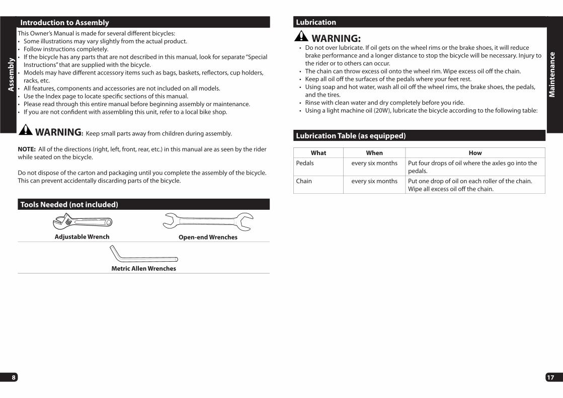
Introduction to Assembly
This Owner’s Manual is made for several diff erent bicycles: • Some illustrations may vary slightly from the actual product. • Follow instructions completely.• If the bicycle has any parts that are not described in this manual, look for separate “Special
Instructions” that are supplied with the bicycle.• Models may have diff erent accessory items such as bags, baskets, refl ectors, cup holders,
racks, etc.• All features, components and accessories are not included on all models.• Use the Index page to locate specifi c sections of this manual.• Please read through this entire manual before beginning assembly or maintenance.• If you are not confi dent with assembling this unit, refer to a local bike shop.
WARNING: Keep small parts away from children during assembly.
NOTE: All of the directions (right, left, front, rear, etc.) in this manual are as seen by the rider while seated on the bicycle.
Do not dispose of the carton and packaging until you complete the assembly of the bicycle. This can prevent accidentally discarding parts of the bicycle.
Ass
em
bly
Tools Needed (not included)
Adjustable Wrench Open-end Wrenches
Metric Allen Wrenches
17
Ma
inte
na
nce
Lubrication
WARNING: • Do not over lubricate. If oil gets on the wheel rims or the brake shoes, it will reduce
brake performance and a longer distance to stop the bicycle will be necessary. Injury to the rider or to others can occur.
• The chain can throw excess oil onto the wheel rim. Wipe excess oil off the chain.• Keep all oil off the surfaces of the pedals where your feet rest.• Using soap and hot water, wash all oil off the wheel rims, the brake shoes, the pedals,
and the tires.• Rinse with clean water and dry completely before you ride.• Using a light machine oil (20W), lubricate the bicycle according to the following table:
Lubrication Table (as equipped)
What When How
Pedals every six months Put four drops of oil where the axles go into the pedals.
Chain every six months Put one drop of oil on each roller of the chain. Wipe all excess oil off the chain.

16
Repair and Service
WARNING:
• Inspect the product frequently. Failure to inspect the product and to make repairs or adjustments, as necessary, can result in injury to the rider or to others. Make sure all parts are correctly assembled and adjusted as written in this manual and any “Special Instructions”.
• Immediately replace any damaged, missing, or badly worn parts with original equipment.
• Make sure all fasteners are correctly tightened as written in this manual and any “Special Instructions”. Parts that are not tight enough can be lost or operate poorly. Over tightened parts can be damaged. Make sure any replacement fasteners are the correct size and type.
NOTE: Have a bicycle service shop make any repairs or adjustments for which you do not have the correct tools or if the instructions in this manual or any “Special Instructions” are not suffi cient for you.
Ma
inte
na
nce
9
Ass
em
bly
Front Wheel Install:
WARNING: • Do NOT use Axle Nuts A without serrations to attach the front wheel.• Ensure wheel spins freely without contacting fork or fender.• Failure to obey these steps can allow the front wheel to loosen while riding. This can cause
injury to the rider or to others.
A
B
C
1. If the Axle Nuts A are already attached to the front wheel axle, begin by removing them and Shoulder Washers B and set aside.
2. Set the wheel fully into the front fork Dropouts C 3. Place a Shoulder Washer B on each end of Axle with small shoulder facing IN as shown.4. Install Axle Nuts A with serrated surface facing IN.5. With the wheel in the center of the fork and tighten both Axle Nuts securely.
10
Ass
em
bly
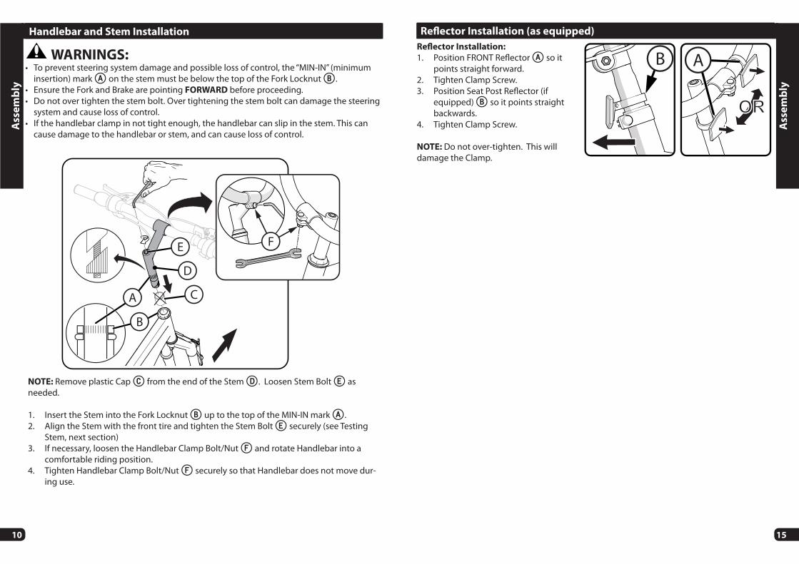
Handlebar and Stem Installation
NOTE: Remove plastic Cap C from the end of the Stem D. Loosen Stem Bolt E as needed.
1. Insert the Stem into the Fork Locknut B up to the top of the MIN-IN mark A.2. Align the Stem with the front tire and tighten the Stem Bolt E securely (see Testing
Stem, next section)3. If necessary, loosen the Handlebar Clamp Bolt/Nut F and rotate Handlebar into a
comfortable riding position.4. Tighten Handlebar Clamp Bolt/Nut F securely so that Handlebar does not move dur-
ing use.
WARNINGS: • To prevent steering system damage and possible loss of control, the “MIN-IN” (minimum
insertion) mark A on the stem must be below the top of the Fork Locknut B. • Ensure the Fork and Brake are pointing FORWARD before proceeding.• Do not over tighten the stem bolt. Over tightening the stem bolt can damage the steering
system and cause loss of control.• If the handlebar clamp in not tight enough, the handlebar can slip in the stem. This can
cause damage to the handlebar or stem, and can cause loss of control.
D
C
E
A
B
F
15
Refl ector Installation (as equipped)
Refl ector Installation:
1. Position FRONT Refl ector A so it points straight forward.
2. Tighten Clamp Screw.3. Position Seat Post Refl ector (if
equipped) B so it points straight backwards.
4. Tighten Clamp Screw.
NOTE: Do not over-tighten. This will damage the Clamp.
B A
Ass
em
bly

14
Pedal Installation
CAUTION: There is a RIGHT pedal marked R and a LEFT pedal marked L.
NOTE: A Pedal Wrench is preferred for attaching Ped-als. A thin open-endwrench can also be used.
• The pedal marked R has right-hand threads. Tighten it in a clockwise direction.
• The pedal marked L has left-hand threads. Tighten it in a counterclockwise direction (anti-clockwise).
• Turn the right pedal marked R into the right side of the crank arm, and the left pedal marked L into the left side of the crank arm.
Tighten the pedals:
• Make sure the threads of each pedal are fully into the crank arm.
WARNING: Ensure pedals are secure in crank arms so they will not loosen. Periodically check tightness.
L
RThree-Piece Cranks (various models)
Maintenance: Both Crank Arms A were tightened to the spindle B at the factory. After riding the bicycle the fi rst few times, make sure the crank arms have not loosened. If either crank arm has loosened during this “break-in” period, re-tighten or have it tightened by a bicycle service shop.
Frequently check the tightness of the crank arms. If loose, tighten or have them tightened by a bicycle service shop.
WARNING: If you ride the bicycle with a loose crank arm, the crank arm may fall off . The spindle may also damage the crank arm.
A
B
Ass
em
bly
11
Testing Stem and Handlebar Tightness
TO TEST THE TIGHTNESS OF THE STEM:
• Straddle the front wheel between your legs.• Try to turn the front wheel by turning the handlebar.• If the handlebar and stem turn without turning the front
wheel, realign the stem with the wheel and tighten the stem bolt(s) tighter than before (about 1/2 revolution only at a time).
• Do this test again, until the handlebar and stem do not turn without turning the front wheel.
TO TEST THE TIGHTNESS OF THE HANDLEBAR CLAMP:
• Hold the bicycle stationary and try to move the ends of the handlebar up and down.
CAUTION: Do not exceed 100 lbs (45 kg) downward force.
• If the handlebar moves, loosen the bolt(s) of the handlebar clamp.
• Put the handlebar in the correct position and tighten the bolt(s) of the handlebar clamp tighter than before.
• If the handlebar clamp has more than one bolt, tighten the bolts equally.• Do this test again, until the handlebar does not move in the handlebar clamp.
Ass
em
bly

12
Ass
em
bly
WARNING: To prevent the Seat coming loose and possible loss of control, the “MIN-IN” (minimum insertion) mark A on the Seat Post must be BELOW the top of the Seat Tube B.
STEP 1- INSERT SEAT POST INTO SEAT
TUBE:
• If needed, loosen Seat Post Clamp Screw D.• Point the Seat forward and put the Seat Post C into the Seat Tube B with the “MIN-IN” marks BELOW the top of the Seat Tube as shown.
STEP 2 - BOLT SEAT CLAMP:
• With Seat Post C inserted according to STEP 1 - Tighten Screw D securely so Seat supports the rider without moving.
Seat Installation
A
A
D
1
2
C
B
C
13
Testing Seat Clamp and Post Clamp Tightness
To test the tightness of the seat clamp and the post clamp:
• Try to turn the seat side-to-side and to move the front of the seat up and down.• If the seat moves in the Seat Clamp:
• Loosen the Seat Clamp Nut.• Put the seat in the correct position and tighten the Seat Clamp tighter than before.• Do this test again, until the seat does not move in the Seat Clamp.
• If the Seat Post moves in the Seat Tube Clamp:
• Loosen the Seat Clamp Lever.• Put the Seat Post in the correct position and tighten the Seat Clamp Nut tighter than
before.• If necessary, tighten or loosen Hand Nut so that Quick Release tightens securely.
• Do this test again, until the Seat Post does not move in the Seat Tube Clamp.
Seat Bolt Saddle Adjustment (various models)
SINGLE BOLT CLAMP:
1. Loosen the Clamp Bolt A suffi ciently to allow any Serrations B on the mechanism to disen-gage before changing the saddle’s angle.
2. With serrations fully re-engaged and saddle in a comfortable riding position, tighten the Clamp Bolt A securely to ensure the saddle will not come loose.
WARNING: Serrations on the mat-ing surfaces of the Clamp can wear with use and adjustment. Check that the Clamp is tight and secure before each ride.
DUAL CLAMP:
3. Loosen Clamp Bolt/Nut C as needed and adjust Seat to a comfortable riding position.
4. With Clamp fully on Seat Post as shown, tighten Bolt/Nut C securely so that seat does not move when in use.
A
C
B
Ass
em
bly