Embed Size (px)
Citation preview

Crack patterns in thin ®lms
Z. Cedric Xiaa, John W. Hutchinsonb,*aFord Research Laboratory, Manufacturing Systems Department, Dearborn, MI 48121, USA
bHarvard University, Division of Engineering and Applied Sciences, 29 Oxford Street, Cambridge,
MA 02138, USA
Received 16 February 1999
Abstract
A two-dimensional model of a ®lm bonded to an elastic substrate is proposed forsimulating crack propagation paths in thin elastic ®lms. Speci®c examples are presented for
®lms subject to equi-biaxial residual tensile stress. Single and multiple crack geometries areconsidered with a view to elucidating some of the crack patterns which are observed todevelop. Tendencies for propagating cracks to remain straight or curve are explored as aconsequence of crack interaction. The existence of spiral paths is demonstrated. 7 2000
Elsevier Science Ltd. All rights reserved.
Keywords: Crack propagation; Thin ®lms; Integral equations
1. Introduction
Films and coatings bonded to substrates often develop in-plane tensile stresseslarge enough to cause cracking. A ®lm deposited at a high temperature and thencooled will develop biaxial in-plane tensile stresses if the thermal expansioncoe�cient of the ®lm exceeds that of the substrate. This is usually the case formetal or polymer ®lms deposited on ceramic substrates, and it is often thesituation for glazes on pottery. Tensile stresses develop in coatings such as paintsand lacquers due to solvent evaporation producing a tendency for the coating to
0022-5096/00/$ - see front matter 7 2000 Elsevier Science Ltd. All rights reserved.
PII: S0022 -5096 (99)00081 -2
Journal of the Mechanics and Physics of Solids
48 (2000) 1107±1131
www.elsevier.com/locate/jmps
* Corresponding author. Tel.: +1-617-495-2848; fax: +1-617-495-9837.
E-mail address: [email protected] (J.W. Hutchinson).

shrink were it is not bonded to the substrate. In much the same way, tensilestresses develop in a constrained layer of mud as drying takes place.
Glaze cracks, mud cracks, crack formations such as the Devils Postpile and theGiant's Causeway, and other crack patterns have long held a fascination formankind. Nevertheless, in most instances, the understanding underlying theevolution of such crack patterns is qualitative at best. In this paper, the focus willbe on cracking behavior in biaxially stressed thin elastic ®lms and coatings thatare well bonded to thick elastic substrates. A two-dimensional model for the ®lm-substrate system is proposed which permits an analytical investigation of a widevariety of ®lm cracking phenomena. A number of solutions based on the modelwill be presented in this paper with the intent of providing the mechanicsunderlying crack path and pattern evolution. These include several interactione�ects, such as conditions establishing crack spacing and the behavior of onecrack advancing toward another. Insight is also provided into the tendency forcracks to kink or curve due to the presence of a neighboring crack. One intriguingtheoretical prediction is the existence of spiral crack paths under conditions wherethe ®lm is subject to equi-biaxial tension. Spiral paths in ®lms do not appear to becommonly observed, but a good example is contained in an early paper by Argon(1959). Dillard et al. (1994) have reported many examples of spiral cracks in thinbrittle adhesive layers bonding together glass plates. Observations of otherunusual crack paths and patterns in thin ®lms and coatings can be found inarticles by Chen and Chen (1995) and Garino (1990).
Crack propagation in a ®lm bonded to a substrate is a three-dimensionalprocess. As depicted in Fig. 1, a crack initiates at a ¯aw and spreads bychanneling. One of the few fully three-dimensional studies of ®lm cracking is thatof Nakamura and Kamath (1992) who analyze an isolated ®nite length through-®lm crack, including its approach to steady-state propagation wherein conditionsat the crack edge become independent of the length of the crack. Remarkably,their results show that a crack whose length is only slightly greater than several®lm thicknesses is already close to steady state, for the case of a ®lm on a rigidsubstrate. The energy release rate G of a steady-state channeling crack in Fig. 1can be obtained from a two-dimensional plane strain analysis, even though theprocess itself is three-dimensional. By considering the energy di�erence betweensections of the ®lm/substrate system far ahead and far behind the crack edge, onecan rigorously obtain results for the energy release rate averaged over the crackedge in terms of plane strain solutions for cracked ®lms. Solutions for steady-statechanneling in ®lms have been presented by Beuth (1992), and further relevantmechanics and results are summarized in the review article by Hutchinson andSuo (1992).
Beuth's (1992) result for the energy release rate averaged over the advancingfront of a semi-in®nite isolated crack is
G � p2
�1ÿ n2�hs02E
g�a, b� �1�
Z.C. Xia, J.W. Hutchinson / J. Mech. Phys. Solids 48 (2000) 1107±11311108

where h is the ®lm thickness, E and n are the Young's modulus and Poisson'sratio of the ®lm, respectively. The Dundur's parameters, a and b, characterizingthe elastic mismatch between the ®lm and the substrate are
a ��Eÿ �Es
�E� �Es
and b � 1
2
m�1ÿ 2ns � ÿ ms�1ÿ 2n�m�1ÿ ns � � ms�1ÿ n� �2�
where Es and ns are the elastic constants of the substrate, respectively, m �E=�2�1� n�� denotes a shear modulus, and �E � E=�1ÿ n2� is a plane strain tensilemodulus. Eq. (1) applies for cracks extending down to the ®lm/substrate interfacewith s0 as the uniform prestress in the ®lm acting normal to the crack line. Theprestress has no shear component acting parallel to the crack, and thus mode-Iconditions hold on the crack edge. The function g�a, b� is presented in Fig. 1.
With Gc as the mode-I fracture toughness of the ®lm measured in units ofenergy per unit area, the condition for propagation of an isolated crack across abrittle ®lm is
G � Gc �3�This condition provides a robust condition to design against extensive ®lmcracking because short cracks and crack-like ¯aws will have energy release rateswhich fall below the steady-state rate (1). When only small ¯aws are present, ®lmcracks will not begin to spread until the prestress and/or ®lm thickness exceeds the
Fig. 1. Steady-state channeling crack in a thin ®lm. The function g�a, b� and the normalized length
de®ning the in-plane resistance of the substrate, l=h, for b � 0 (the dependence on b is weak).
Z.C. Xia, J.W. Hutchinson / J. Mech. Phys. Solids 48 (2000) 1107±1131 1109

steady-state requirement (3). On the other hand, the Nakamura±Kamath studyshows that any crack-like ¯aws must be small compared to the ®lm thickness ifcrack spreading is likely to be postponed to stress/thickness levels signi®cantlyabove the steady-state requirement (3). Film cracking is frequently in¯uenced byenvironmental factors, producing some degree of time-dependence of crackgrowth. Humidity a�ects the propagation of cracks in glasses, and curing anddrying are inherently time-dependent.
The steady-state energy release rate (1) is modi®ed by various e�ects. If thesubstrate is very sti� compared to the ®lm, the channeling crack may not reachthe interface with the substrate. This possibility and the determination of thedepth attained by the crack is discussed by Beuth (1992). Conversely, dependingon the elastic mismatch and the toughness of the substrate relative to the ®lm, thecrack may penetrate into the substrate (Ye et al., 1992). Another commonlyobserved phenomenon is ®lm debonding accompanying the channeling crack (Yeet al., 1992) which can occur if the interface toughness is su�ciently lowcompared to that of the ®lm and substrate. There exists a range of the interfacetoughness, relative to the ®lm toughness, such that the debonded region leftbehind by the advancing crack front has a well de®ned width on either side of the®lm crack. Plastic yielding in the substrate induced by the ®lm crack also resultsin a modi®cation of G (Hu and Evans, 1989; Beuth and Klingbeil, 1996).
Each of the above mentioned e�ects can in¯uence ®lm crack interaction and thepaths that cracks follow. There are instances, for example, in which a propagating®lm crack induces a interface debond on one side of the crack but not the other.This produces a strong asymmetry with respect to the crack tip, causing the crackto follow a curved trajectory. Such auxiliary e�ects will not be considered in thispaper. Attention will be limited to ®lm cracks unaccompanied by substratecracking, interface debonding or substrate yielding.
2. The model
2.1. Formulation
A uniform, isotropic elastic ®lm bonded to an isotropic substrate is modeled asa sheet of thickness h attached to an elastic foundation. Prior to cracking, the ®lmis uniformly stressed such that sab � s0ab: A plane stress approximation is used todescribe the in-plane deformation of the ®lm in the presence of cracks, withua�x1, x2� as the in-plane displacements averaged through the thickness of the ®lmand measured relative to the uniform prestressed state. The associated average in-plane strains are. eab�1=2�ua;a�ub;b�: The average stresses in the ®lm are
sab � s0ab � Dsab �4a�
where Dsab is the average through the thickness of the stress changes due tocracking. The average stress changes are related to the average strain changes by
Z.C. Xia, J.W. Hutchinson / J. Mech. Phys. Solids 48 (2000) 1107±11311110

Dsab � E
1ÿ n2��1ÿ n�eab � neggdab
� �4b�
where any e�ect of Ds33 has been neglected. Greek subscripts range from 1 to 2 inthe usual convention for plane stress.
Denote the in-plane components of the restoring force per unit area exerted onthe ®lm by the substrate by fa: Equilibrium requires that the stress averagesexactly satisfy hsab, b � fa � 0: The elastic restoring force per unit area exerted bythe substrate on the ®lm is modeled by fa � ÿkua where the spring constant k willbe identi®ed later. The associated Navier equations governing the displacements ofthe ®lm are
1
2�1ÿ n�ua, bb � 1
2�1� n�ub, ba �
�1ÿ n2�kEh
ua �5�
A traction-free crack must satisfy sabnb � 0 at every point along the crack, wherenb is the unit normal to the crack line, such that the average traction changescancel the pre-tractions, i.e. Dsabnb � ÿs0abnb:
According to the model, an elastic substrate does not alter the character of thedominant singular behavior at the tip of the crack in the ®lm. The stress changesat the crack tip governed by Eq. (5) have the conventional mode I and II inversesquare root singularities of plane stress with amplitudes KI and KII de®ned in thestandard manner. The strain energy per area per unit thickness of ®lm is
W �W 0 � DW
where DW ��s0abeab �
1
2sabeab
�� 1
2
�k
h
�uaua
�6�
with W 0 as the elastic energy density stored in the ®lm prior to cracking. Theelastic energy per unit area in the model ®lm/substrate system is hW. Energycontributions in the ®lm from through-thickness variations departing from theaverage stresses and strains are neglected in Eq. (6). With the strain energy of thesystem de®ned as the area integral of Eq. (6),
�hW dA, the principle of minimum
potential energy for the model leads precisely to Eq. (5) as the associated Eulerequations. The energy release rate of the crack (energy release per unit of crackadvance per unit thickness of ®lm) is related to the stress intensity factors by theclassical plane stress relation G � �K 2
I � K 2II�=E: A path-independent J-integral
exists for the model whose value coincides with G:
J ��C
�Wn1 ÿ sabnbua,1
�ds �7�
where C is any contour circling the tip in the counter-clockwise sense with na asits outward unit normal and ds as its element of length. The x1-axis must bealigned parallel to the crack line at the tip.
The fracture behavior of the ®lm is assumed to be isotropic with Gc as the
Z.C. Xia, J.W. Hutchinson / J. Mech. Phys. Solids 48 (2000) 1107±1131 1111
mode-I toughness. In applying the model to predict a crack propagation pathunder quasi-static conditions, the path is required to evolve such that pure mode-Iconditions �KII � 0� are maintained at the tip with G � Gc: A pre-existing ®lmcrack subject to increasing prestress may experience combined mode-I and -IIconditions at its tip. The crack will initiate growth by kinking in the direction forwhich KII of the putative crack increment vanishes. Once growth has beeninitiated, however, the path is expected to evolve smoothly such that KII � 0: Theemphasis in this paper in the ®rst instance is not on the prediction of detailedpaths, but rather on the production of a variety of crack solutions which willsupply qualitative insight into the way crack paths are expected to develop in thin®lms. To this end, solutions to the model will be presented for a variety of crackgeometries in the form of the crack tip intensity measures, KI and KII: Most of theresults will be presented for ®lms subject to an equi-biaxial stress state, s0ab �s0dab:
2.2. Solution for a semi-in®nite straight crack and calibration of model
Consider an isolated semi-in®nite straight crack coincident with the negative x1-axis and subject to initial stresses with s012 � 0: Symmetry dictates that mode-Iconditions prevail at the tip. Far behind the tip, the displacement ®eld isindependent of x1. The solution to the Navier equations (5) is readily obtained as
u1 � 0 and u2 � s022
�������h
�Ek
reÿ�����������k
�Ehx 2
r�8�
where �E � E=�1ÿ n2�: The associated stress changes far behind the tip are
Ds12 � 0, Ds11 � nDs22 and Ds22 � ÿs022eÿ�����������k
�Ehx 2
r�9�
The remote changes do not depend on s011: The energy release rate can beobtained either by a simple energy argument, accounting for the energy changedue to a unit advance of the crack tip, or by a direct evaluation of J using acontour remote from the tip. The result is
G ��������h
�Ek
rs0
2
22 �10�
The model is calibrated with the exact solution for the semi-in®nite mode-I crackgiven in Section 1. We choose the substrate spring constant k such that G in Eq.(10) coincides with Eq. (1) with the result that k must satisfy:������
�E
kh
s� p
2g�a, b� �11�
Z.C. Xia, J.W. Hutchinson / J. Mech. Phys. Solids 48 (2000) 1107±11311112

If the ®lm is very compliant relative to the substrate, the ®lm crack may not reachthe interface with the substrate, as discussed in Section 1. Beuth's (1992) resultsmay be used to adjust Eq. (11) to account for crack depths which are less than h,but this is generally a small correction.
It is convenient to introduce the reference length l, characterizing theexponential decay of the changes transverse to the crack in Eqs. (8) and (9):
l ���������Eh
k
s� p
2g�a, b�h �12�
In the absence of any elastic mismatch between ®lm and the substrate �a � b � 0�,l � 1:98h: From the plot in Fig. 1, it can be seen that l will greatly exceed the ®lmthickness h when the ®lm is very sti� compared to the substrate �a11� and will beof the order of h when the ®lm is very compliant relative to the substrate �a1ÿ1�:
3. Integral equation formulations
The Navier equations (5) can be written in a dimensionless form such that h, Eand k are absorbed into the dimensionless displacements ua=l4ua and coordinatesxa=l4xa as
1
2�1ÿ n�ua, bb � 1
2�1� n�ub, ba � ua �13�
In this section and in Appendix A, dimensionless displacements and coordinateswill be used, and k will enter into the results only through l, which is absorbedinto the dimensionless variables. In the other sections, dimensional quantities willbe used. With these dimensionless quantities, eab � 1
2�ua;b � ua;b�, and the stressesare still given by Eq. (4). Let f and c be two scalar functions of the coordinates,and introduce the Helmholtz representation, ua � f;a � eabc,b, where eab is thepermutation tensor. The Navier equations (13) then can be rewritten as
ÿr2fÿ f
�,a�eab
�1
2�1ÿ n�r2cÿ c
�,b� 0 �14�
with stress changes due to cracking as
Ds11 �ÿE=�1ÿ n2�
��f,11 � nf,22 � �1ÿ n�c,12
�Ds22 �
ÿE=�1ÿ n2�
��f,22 � nf,11 ÿ �1ÿ n�c,12
�
Z.C. Xia, J.W. Hutchinson / J. Mech. Phys. Solids 48 (2000) 1107±1131 1113

Ds12 �ÿE=�1ÿ n���f,12 ÿ
1
2
ÿc,11 ÿ c,22
�� �15�
Integral equation formulations will be used to construct solutions to the problemsconsidered in this paper which cannot be solved analytically. In conventionalcrack problems in two-dimensional elasticity, integral equations are formulatedusing dislocations as the kernel functions (e.g. Rice, 1968), leading to integralswith Cauchy singularities. For the present model of ®lm cracking, a formulationbased on dislocation doublets is more natural than one based on dislocations.Stresses due to a dislocation in the ®lm are ®nite at in®nity on each side of thedislocation line due to interaction with the underlying substrate, while the stressesproduced by a dislocation doublet fall o� exponentially far from the doublet. Thedoublet formulation has integrals with kernels whose singularities are of order1=r2: This class of integral equations has been labeled `strongly singular', andmethods analogous to those for Cauchy equations have recently come availablefor computing numerical solutions (Kaya and Erdogan, 1987; Willis and Nemat-Nasser, 1991).
3.1. Doublet solution
To de®ne the dislocation doublets, introduce two dislocations of equalmagnitude but opposite sense on the x1-axis spaced a distance 2e apart. With theamplitude of the dislocation on the right speci®ed by b, bring the dislocationstogether such that d � lim
e40�2eb�: (Here, b and d are dimensionless. The
dimensional quantities are scaled by l and l2, respectively.) The dominantsingularity of the doublet is una�ected by interaction with the substrate andtherefore the same as in plane stress. With �r, y� as polar coordinates centered atthe doublet and d � �d1, d2�, the dominant singularity is
Ds11 � E
4pr2�ÿ d1�sin 2y� sin 4y� � d2cos 4y
�
Ds22 � E
4pr2�ÿ d1�sin 2yÿ sin 4y� � d2�2cos 2yÿ cos 4y�
�
Ds12 � E
4pr2�ÿ d1cos 4y� d2�sin 4yÿ sin 2y�
��16�
The corresponding Helmholtz functions are
f � 1
8p
�d1�1ÿ n�sin 2y� d2
ÿ2�1� n�ln rÿ �1ÿ n�cos 2y
��
c � 1
4p� ÿ d1cos 2yÿ d2sin 2y� �17�
Z.C. Xia, J.W. Hutchinson / J. Mech. Phys. Solids 48 (2000) 1107±11311114

The full doublet solution satis®es Eq. (14) and must approach Eqs. (16) and (17)as r40: The exact representation for the doublet was found after lengthymanipulation; it is
f � 1
p
�ÿ d1
o2F�r�sin 2y� d2
4
�ÿ �1� n�K0�r� � 4
o2F�r�cos 2y
��
c � 1
p
�d1F�or�cos 2y� d2F�or�sin 2y
� �18a�
where
F�r� � 1
rK1�r� � 1
2K0�r� ÿ 1
r2and o �
������������2
1ÿ n
r�18b�
with K0 and K1 as Bessel functions of the second kind of order zero and one,respectively. The associated stresses are written in a form to expose the singularnature of the doublet solution
Ds11 � E
4p
8>>>><>>>>:ÿd1
��1
r2� B1�r�
�sin 2y�
�1
r2� B2�r�
�sin 4y
��d2
��c1ln r� C1�r�� �
�1
r2� B2�r�
�cos 4y
�9>>>>=>>>>;
Ds22 � E
4p
8>>>><>>>>:ÿd1
��1
r2� B1�r�
�sin 2yÿ
�1
r2� B2�r�
�sin 4y
��d2
��c2ln r� C2�r�� � 2
�1
r2� B1�r�
�cos 2yÿ
�1
r2� B2�r�
�cos 4y
�9>>>>=>>>>;
Ds12 � E
4p
8>>>><>>>>:ÿd1
��c3ln r� C3�r�� ÿ
�1
r2� B2�r�
�cos 4y
��d2
�ÿ�1
r2� B1�r�
�sin 2y�
�1
r2� B2�r�
�sin 4y
�9>>>>=>>>>; �19�
The ®ve functions Bi�r� and Ci�r� are regular functions of r at r � 0: Thesefunctions, along with the three constants ci, are given in Appendix A. The rÿ2
singularity in the stresses is seen to coincide with Eq. (16), and the next mostsingular terms are logarithmic. There are no contributions of order rÿ1: All theother contributions are well behaved at the doublet origin. It should beemphasized that Eq. (19) holds for a dislocation pair on the x1-axis. Results forother orientations of the pair can be obtained by coordinate transformation.
Z.C. Xia, J.W. Hutchinson / J. Mech. Phys. Solids 48 (2000) 1107±1131 1115

3.2. Formulation for a single straight crack
Consider a crack in the ®lm of length 2a (i.e. of dimensional length 2al�extending from ÿa to a along the x1-axis. The prestress in the ®lm is s0ab � s0dab:A distribution of doublets, d1 � 0 and d2 � d�Z� for jZj < a, along x1-axiscanceling the normal traction due to the prestress can be used to construct thesolution for the crack. The resulting integral equation for the d�Z� is
E
4p
�aÿa
"1
�xÿ Z�2 � c2lnjxÿ Zj � A�xÿ Z�#d�Z� dZ � ÿs0 for jxj < a �20�
where A�r� � C2�r� � 2B1�r� ÿ B2�r� is analytic at r � 0: The representation (20) isformal in that the term containing the kernel, �xÿ Z�ÿ2, is unbounded withoutspecial de®nition. A ®nite contribution can be de®ned to give the equation precisemeaning (Kaya and Erdogan, 1987; Kaw, 1991; Willis and Nemat-Nasser, 1991).The solution to Eq. (20) will be given in the next section.
3.3. An alternative formulation
When the crack is curved, terms of order rÿ1 arise in the kernel due tocoordinate transformations along with those of order rÿ2, and the existingnumerical methods are not applicable as they stand. Therefore, it has beennecessary to recast the equations by reducing the order of the singularity to aCauchy-type singularity. Consider a crack of length a, straight or curved, and let sbe the length measured from one end with ds as the line element. Let x be anypoint in the plane o� the crack, and let Dsab�x� be the stress at that point due tothe distribution of doublets d�s� along the crack. Write Dsab�x� as
Dsab�x� ��a0
hS0ab
ÿx, x 0
� � d�s 0 � � S1ab
ÿx, x 0
� � d�s 0 �i ds 0 �21�
where x 0 is the position vector to the crack at s 0: Further, takeP0
ab to representonly the terms with singularity rÿ2 in Eq. (19) (i.e. the stresses in Eq. (16)) and letP1
ab represent the remaining terms. By virtue of the fact that Eq. (16) is the planestress dislocation doublet solution, the contribution from the integrand,� P0
ab �d ds, is precisely the same as is obtained from distributing dislocations b�s�along the crack according to�a
0
hS0
ab
ÿx, x 0
� � d�s 0 �i ds 0 ��a0
hS0
ab
ÿx, x 0
� � b�s 0 �i ds 0 �22�
where b�s� � ÿdd=ds and S0ab is the classical stress ®eld of a dislocation in plane
stress.With d�s� � � as b�s 00 � ds 00, the second contribution in Eq. (21) is
Z.C. Xia, J.W. Hutchinson / J. Mech. Phys. Solids 48 (2000) 1107±11311116

�a0
hS1ab
ÿx, x 0
� � d�s 0 �i ds 0 ��a0
�S1ab
ÿx, x 0
� � �as
b�s 00 � ds 00�
ds 0 �23�
Noting that the integration on the right-hand side of Eq. (23) is over a triangle inthe �s 0, s 00 � plane, interchange the order of integration to obtain�a
0
hS1ab
ÿx, x 0
� � d�s 0 �i ds 0 ��a0
�S1ab
ÿx, x 0
� � �as
b�s 00 � ds 00�
ds 0 �24�
where
S1ab
ÿx, x 00
� � �s}0
S1ab
ÿx, x 0
�ds 0 �25�
It follows, therefore, the doublet representation (21) can be replaced by an integralof a distribution of dislocations b�s� according to
sab�x� ��a0
hS0ab
ÿx, x 0
�� S1ab
ÿx, x 0
�i � b�s 0 � ds 0 �26�
where S0ab is the stress distribution (23) for a dislocation with singularity �xÿ
x 0 �ÿ1 and the contribution to the kernel from S1ab�x, x 0 � is bounded as x4x 0:
Integral equations formed from Eq. (26) are of the classical Cauchy-type anddirectly amenable to numerical solution by methods such as those detailed byErdogan and Gupta (1972). The relation of the stress intensity factors to thedislocation distributions at the ends of the cracks is the same as in the classicalplane stress formulation.
4. Straight cracks
Solutions to a number of problems for straight ®lm cracks will be presented inthis section. With two exceptions, where analytical results have been obtained, thesolutions have been obtained numerically based on one of the two integralequation formulations described in the previous section. The selection of problemsis intended to provide insight into interactions between ®lm cracks and their rolein establishing cracking patterns. The subsections consider: a single ®nite crack;arrays of parallel semi-in®nite cracks; mixed mode interactions among parallelcracks; and interactions between perpendicular cracks.
4.1. Single ®nite crack
The integral equation (20) employing the doublet distribution was solvednumerically using methods developed in the references cited earlier. The prestressin the ®lm is equi-biaxial tension with s0ab � s0dab: Symmetry dictates the crack tobe in mode I �KII � 0�: The near tip ®eld is thus characterized by KI: Results will
Z.C. Xia, J.W. Hutchinson / J. Mech. Phys. Solids 48 (2000) 1107±1131 1117

also be presented for the contribution from the next order in the hierarchy ofcrack tip ®elds, the T-stress, s11 � T, which is ®nite at the tip. The dependence ofKI=s0
��lp
and T=s0 on the normalized crack half-length, a=l, is shown in Fig. 2.The results have been computed for n � 0:3, as will be the case for all thenumerical results presented in the paper. For a=l � 1, the stress intensity factor isalready close to the asymptotic limit for a semi-in®nite crack
KI
s0��lp �
�����������������1ÿ n2�
p�27�
which is obtained from Eqs. (10)±(12). Recall that l has been de®ned in Eq. (12)such that this limiting result is exact. The trend shown in Fig. 2 is in accord withthe three-dimensional result of Nakamura and Kamath (1992) quoted in Section1. One end of the crack ceases to be a�ected by the other end when the cracklength is larger than about 2l, i.e., about four times the ®lm thickness in theabsence of elastic match between the ®lm and substrate. The elastic mismatchbetween the ®lm and the substrate makes its presence felt through l, which isplotted as l=h in Fig. 1.
The T-stress is also plotted in Fig. 2. The prestress component s011 � s0 actingparallel to the crack is accounted for in this result. (When the prestress is notequi-biaxial, the e�ect of s011 on T is readily adjusted by superposition. This samecomponent has no e�ect on KI:) The interaction of the crack with the substrategives rise to a positive T-stress. The corresponding plane stress problem for asheet unattached to a substrate tension has T � 0: A positive T-stress hasimplications for the con®gurational stability of the straight crack (Cotterell andRice, 1980), giving rise to the possibility that small perturbations may cause thecrack path to depart from its initial direction. A stability analysis for the full ®lm/
Fig. 2. Stress intensity factor and T-stress for a ®lm crack subject to equi-biaxial tension �n � 0:3�:
Z.C. Xia, J.W. Hutchinson / J. Mech. Phys. Solids 48 (2000) 1107±11311118

substrate model has not been performed, and thus the role of T may not be thesame as for a free standing ®lm.
4.2. Parallel semi-in®nite cracks, including sequential cracking
Consider the in®nite array of equally spaced semi-in®nite ®lm cracks withaligned tips shown in Fig. 3. Symmetry again dictates that each crack tip is inmode I. The energy release rate of each crack tip is readily calculated byimagining all the cracks to advance by an unit increment, thereby, equivalently,transferring a unit increment of the ®lm far ahead of the tips to the remote wake.The solution to Eq. (13) in the remote wake depends only on x2 and is easilyproduced. The requisite energy accounting gives
G � ls02
�Etanh
�H
2l
�or
KI
s0��lp �
�����������������1ÿ v2�
p ��������������������tanh
�H
2l
�s�28�
This result approaches the result for an isolated semi-in®nite crack in Eq. (10) orEq. (27) when the crack spacing H exceeds approximately 3l: Elastic mismatch,appearing through l, has a fairly strong in¯uence on the interaction. Cracks in a®lm which is sti� relative to its substrate interact across greater distances than viseversa.
Exact results for G for the array of equally spaced cracks channeling in steady-state across the ®lm can be obtained from the plane strain solution for periodic
Fig. 3. Energy release rate at each crack tip for steady-state channeling of parallel ®lm cracks. The
upper curve applies to simultaneous advance of all the cracks, while the lower curve applies to the
sequential process where a new set of cracks propagates midway between a previously formed set of
cracks.
Z.C. Xia, J.W. Hutchinson / J. Mech. Phys. Solids 48 (2000) 1107±1131 1119

edge cracks in the ®lm. Denote the solution for the energy release rate for thetwo-dimensional plane strain problem for cracks of length a (where aRh� withspacing H by Gps�a�: A simple energy argument (Hutchinson and Suo, 1992)provides the connection between the two energy release rates as
G � 1
h
�h0
Gps�a� da �29�
Solutions for Gps�a� are not available for periodic crack arrays in ®lms with elasticproperties which di�er from the substrate, but accurate numerical results areavailable for homogeneous, isotropic elastic solids (Tada et al., 1985). Evaluationof Eq. (29) using these accurate numerical results reveals that the approximateestimate of G for the present model (28) for the case of no elastic mismatch isaccurate to within a few percent over the entire range of H=l:
The energy release rate for an idealized sequential cracking process which ismore in accord with the way ®lm cracks appear can also be obtained simply.Consider the semi-in®nite mode-I cracks in Fig. 3 advancing midway betweenpreviously formed in®nite cracks. Because the solution to Eq. (13) is far aheadand far behind the current location of the crack tips is elementary, it is verysimple to do the energy accounting necessary to obtain the energy released byeach semi-in®nte crack. The results is
G � ls02
�E
�2tanh
�H
2l
�ÿ tanh
�H
l
���30�
Alternatively, following the procedure of Hutchinson and Suo (1992), denote theresult from Eq. (28) for aligned semi-in®nite cracks in Fig. 3 spaced a distance 2Hapart by G 0�2H �: The energy released by propagation of the ®rst set of cracks farahead of the current set of crack tips in Fig. 3 is G 0�2H �, per height 2H in the x2direction, while that released far behind the tips is 2G 0�H � per height 2H. Theenergy release rate per tip is therefore precisely G � 2G 0�H � ÿ G 0�2H �: Eq. (30)follows immediately using Eq. (28). It is worth recording that the connection G �2G 0�H � ÿ G 0�2H � is exact within the context of three-dimensional elasticity. Anyerror in Eq. (30) follows from the fact that Eq. (28) is derived from the presentmodel which approximates the ®lm/substrate interaction for the periodic cracks.
The two results, (28) and (30), are compared in Fig. 3. The energy release forcracks nucleated sequentially is signi®cantly less than the prediction for an arrayof crack imagined to appear simultaneously. This di�erence has importantimplications for the relation between crack spacing and residual stress. Delannayand Warren (1991) and Thouless et al., 1992 carried out experiments to obtain theevolution of average crack spacing in brittle ®lms under conditions where theprestress was continuously increased. In both papers, the experiential data wascompared to a theoretical prediction for sequential cracking similar, but notidentical to Eq. (30). If Gc is the mode-I ®lm toughness and if 2H is the currentcrack spacing, then Eq. (30) with G � Gc speci®es the stress s0 at which the next
Z.C. Xia, J.W. Hutchinson / J. Mech. Phys. Solids 48 (2000) 1107±11311120

set of cracks will channel halfway between the current set according to theidealized sequential processes.
4.3. Mixed mode interactions among parallel cracks
The problems posed in this subsection are intended to provide insight intocracking trajectories when ®lm cracks are within interaction distance. The primaryemphasis is the mix of mode I and II at the tip, from which the direction of crackadvance can be inferred. The fracture properties of the ®lm are taken to beisotropic. The solutions to the problems posed below were produced using themethod of Section 3.3. As in the previous two subsections, it is assumed that theprestress in the ®lm is equi-biaxial tension. However, the component s011 has noin¯uence on the stress intensity factors in these problems if the cracks are parallelto the x1.
A pair of aligned ®lm cracks of length 2a lying side by side a distance 2H apartis considered in Fig. 4. Stress intensity factors, KI and KII, of the right-hand tip ofthe upper crack are shown. There is some interaction when H=l � 2, but, forH=l � 5, KI is nearly identical to the result for the isolated crack in Fig. 2 andKII � 0: The cracks become e�ectively semi-in®nite as far as the stress intensityfactors are concerned when a=l > 2: The mode-II stress intensity factor KII of theupper, right-hand tip is negative. This implies that a putative crack advancingfrom that tip would kink upward. Crack paths evolving from these two startercracks will spread apart rather than come together. In this sense, the two alignedcracks `repel' each other.
Results illustrating the behavior expected for cracks propagating towards eachother can be inferred from the results displayed in Fig. 5. A semi-ini®nite crackadvancing to the right encounters two aligned semi-in®nite cracks advancing inthe opposite direction. The middle crack lies precisely half way between the twoouter cracks and is therefore in mode I. The outer cracks shield the middle crack(Fig. 5(a)) when the tip of the middle crack passes between the outer cracks. Thestress intensity factors for the upper crack are shown in Fig. 5(b) and (c). Theenergy release rate (not shown) of this crack also drops as the tips pass eachother. The mode-II stress intensity factor of the upper crack changes sign as thetips pass each other. (For the upper crack with the tip pointing to the left, apositive KII is de®ned such that it produces a positive shear stress component, s12,directly to the left of the tip.) The trend of KII shown in Fig. 5(c) implies that theouter cracks tend to veer away from the middle crack as the tips approach eachother, and then switch direction and veer toward the middle crack after the tipshave passed.
Crack paths in unsupported thin sheets and plates have been addressed usingelastic fracture mechanics by a number of authors. In particular, Melin (1983) hasshown that the behavior noted above for ®lm cracks approaching each other alsooccurs in brittle free standing sheets. Broberg (1987) provides general discussion ofcrack paths and a comprehensive list of references.
Z.C. Xia, J.W. Hutchinson / J. Mech. Phys. Solids 48 (2000) 1107±1131 1121

4.4. Interaction between perpendicular cracks
Consider a semi-in®nite crack approaching an in®nite crack at a right angle asshown in Fig. 6(a). The pre-stress in the ®lm is equi-biaxial tension s0: Symmetrydictates the advancing crack to be mode I. When the tip of the advancing crack iswithin 3l from the other crack, its stress intensity factor begins to drop below Eq.(27), falling to a minimum at a distance of 0:3l: The intensity factor then increasessharply as the remaining ligament is reduced to zero. The present model may notbe reliable in the range for x=l < 0:3: Three-dimensional e�ects are expected tobecome important when size of the controlling region is of the order of the ®lmthickness. The trend in Fig. 6(a) suggests that an advancing crack may arrest at a
Fig. 4. Mode I and II stress intensity factors for the upper right hand crack tip for two aligned parallel
cracks �n � 0:3�:
Z.C. Xia, J.W. Hutchinson / J. Mech. Phys. Solids 48 (2000) 1107±11311122

Fig. 5. Stress intensity factors for parallel cracks approaching one another �n � 0:3�:
Z.C. Xia, J.W. Hutchinson / J. Mech. Phys. Solids 48 (2000) 1107±1131 1123
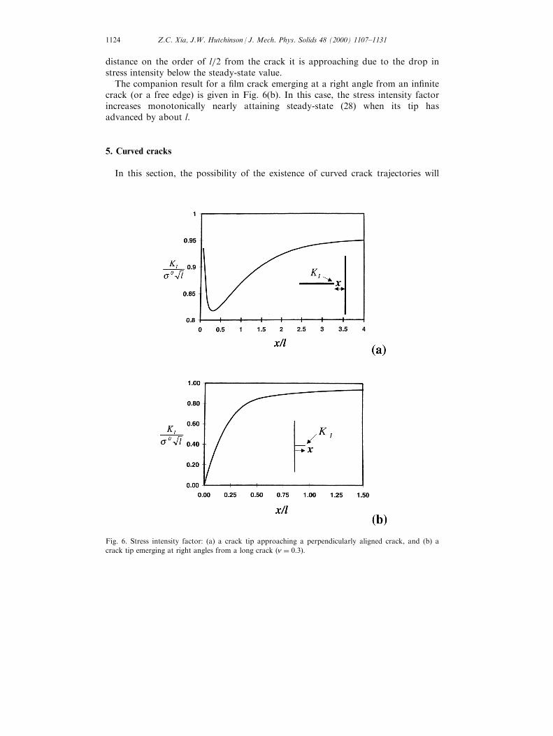
distance on the order of l=2 from the crack it is approaching due to the drop instress intensity below the steady-state value.
The companion result for a ®lm crack emerging at a right angle from an in®nitecrack (or a free edge) is given in Fig. 6(b). In this case, the stress intensity factorincreases monotonically nearly attaining steady-state (28) when its tip hasadvanced by about l.
5. Curved cracks
In this section, the possibility of the existence of curved crack trajectories will
Fig. 6. Stress intensity factor: (a) a crack tip approaching a perpendicularly aligned crack, and (b) a
crack tip emerging at right angles from a long crack �n � 0:3�:
Z.C. Xia, J.W. Hutchinson / J. Mech. Phys. Solids 48 (2000) 1107±11311124

be explored, and it will be demonstrated that a crack propagating in a spiral pathis possible.
5.1. Circular arc cracks
Consider the ®lm crack in Fig. 7 in the shape of a circular arc of radius R withsubtended angle 2y: The prestress in the ®lm is equi-biaxial tension s0: Theintegral equation formulation of Section 3.3 was used to generate the numericalresults for the stress intensity factors which are presented for the right hand tip.For cracks having R=lr5, the curvature ceases to have any noticeable e�ect, andnear mode I conditions prevail at the tip. At crack radii less than this level, theenergy release rate falls below the rate for an isolated straight crack (27). The signof KII is such that the crack would kink or turn outward from the circular arc, i.e.
Fig. 7. Stress intensity factors for a circular ®lm crack �n � 0:3�:
Z.C. Xia, J.W. Hutchinson / J. Mech. Phys. Solids 48 (2000) 1107±1131 1125

upwards in Fig. 7. This is the same trend predicted for a plane stress crack in asheet under equi-biaxial biaxial stressing. The plane stress results for a circular arcin a biaxially stressed thin sheet (Tada et al., 1985) are approached by the presentsolution when R=l becomes very small, providing a check on the present numericalprocedures. The curves in Fig. 7 for R=l � 0:1 are reasonably well approximatedby this limiting result. This small cracks are not expected to realisticallycharacterized by the present model because three-dimensional e�ects becomedominant.
The sign of KII of the circular arc crack is such it would evolve in such a waythat it would reduce its curvature and asymptote to a straight path once criticalconditions are met. When this observation is combined with the tendency of a tipof a straight crack to be `attracted' to any crack it parallels (cf. Fig. 5), a clue forstarting conditions which might lead to a spiraling crack emerges. Consider thetwo circular arc cracks having common center shown in Fig. 8. The inner crack issu�ciently long (subtending a total angle of 1808) such that its ends do notinteract with each other or with the ends of the outer crack. It could equally wellbe taken as a full circular crack. The radius of the outer crack is R + H, and itslength is also su�ciently great such that the intensity factors at one end have noe�ect on those at the other end. When H is small enough, the tip of the outercrack is expected to be attracted to the inner crack, on the grounds cited above.However, as H increases, the sign of KII must change such that when H is largeenough the tip will de¯ect outward when propagation occurs. By continuity, theremust exist a spacing H such that KII � 0: At this spacing, the tip of the outercrack will advance smoothly in a circular arc and maintain its distance h from theinner crack, either until it senses the ends of the inner crack or it senses its ownends had the inner crack been taken as a full circle.
The problem posed for the circular arc cracks in Fig. 8 has been solved usingthe method of Section 3.3. For speci®ed values of R=l, the stress intensity factorsfor the tips of the outer crack were computed as a function of H=l: The value ofH=l for which KII � 0 was determined. This value is plotted as a function of R=lin Fig. 8(a) over the range of values for which the model is expected to havephysical validity. The corresponding value of KI is shown in Fig. 8(b). Nocorresponding location exists with KII � 0 when the shorter crack lies inside thelonger crack. Then, the two trends cited in the previous paragraph each act so asto attract the tip of the shorter crack towards the longer crack.
The results of Fig. 8(a) for the location of a mode-I tip are now employed tomake an approximate prediction for the path of a spiral crack. The fundamentalassumption is that the crack tip must maintain mode-I conditions at its tip �KII �0� as it advances. Denote the result for spacing between the tip and the innercrack in Fig. 8(a) by H=l � f�R=l�: In planar polar coordinates �r, y�, let r�y� bethe equation of the spiral where y increases monotonically. The path isapproximated by the following equation:
r�y�lÿ r�yÿ 2p�
l� f
�r�yÿ 2p�
l
��31�
Z.C. Xia, J.W. Hutchinson / J. Mech. Phys. Solids 48 (2000) 1107±11311126

where the tip is currently at �r�y�, y�: In applying the solution of Fig. 8(a), thedistance H has been identi®ed as r�y� ÿ r�yÿ 2p�, and the radius of curvature ofthe loop of the crack path is directly opposite the tip is approximated as r�yÿ 2p�:An initial spiral-like loop must pre-exist to initiate a full spiral. As an illustration,assume an initial spiral crack has the form
r
l� r0
l� f
�r0l
�y2p
for 0RyR2p �32�
The starter loop (32) only satis®es (31) exactly at y � 2p: For yr2p, Eq. (32) isused to generate the spiral. An example is shown in Fig. 9 for the startingcondition r0=l � 3: It is evident that the approximation (31) will be virtually
Fig. 8. Stando� H for KII � 0 and associated mode-I stress intensity factor for a circular arc crack
outside a circular crack �n � 0:3�:
Z.C. Xia, J.W. Hutchinson / J. Mech. Phys. Solids 48 (2000) 1107±1131 1127

una�ected if the actual radius of curvature of the loop segment opposite the tip isused in place of r�yÿ 2p�:
Arguments for the existence of spiral cracks have been made on the groundsthat they supply a very e�cient mechanism for relieving the elastic energy storedin the ®lm. That argument is insu�cient, however, because it does not take intoaccount the fact that a crack in a brittle ®lm grows at its tip, advancingcontinuously such that mode-I conditions are maintained. The present modelshows that spiral mode-I paths can exist in biaxially stresses ®lms if spiral-shaped¯aws are present to get them started. An isolated spiral crack was photographedby Argon (1959) in a surface layer under residual tension on a Pyrex glass plate.We are indebted to Argon for calling this pattern to our attention as it providedthe initial motivation behind the present e�ort to seek a theoretical explanationfor spirals. Profuse spiral tunnel cracking has been observed by Dillard et al.(1994) in brittle adhesive layers bonding together glass plates. An example isdisplayed in Fig. 10, where the crack is photographed through one of the plates.As the adhesive cures, biaxial tensile stress develops ®rst producing `mud cracks'that subdivide the adhesive into polygonal regions. With further curing, spiralcracks nucleate and form within the polygonal regions. Most of these cracksappeared to nucleate at or near the polygonal boundary and then spiral inward.These cracks are unlike the ®lm cracks contemplated in the present model in otherrespects as well. While the `mud cracks' extend all the way through the adhesiveat right angles to the adhesive/glass interfaces, each spiral crack is con®ned nearone interface and propagates at an inclined angle to the interface. It is thisinclination which makes the crack opening appear so large.
Fig. 9. Spiral crack pattern satisfying KII � 0 as it evolves �n � 0:3�:
Z.C. Xia, J.W. Hutchinson / J. Mech. Phys. Solids 48 (2000) 1107±11311128

Acknowledgements
This work was supported in part by NSF Grants CMS-96-34632 and DMR-94-00396 and in part by the Division of Engineering and Applied Sciences, HarvardUniversity.
Appendix A. Details of the doublet solution
The functions Bi�r� and Ci�r� in Section 3.1 are de®ned as follows.
C1�r� ��
1ÿ n4�1� n� ÿ
1� n2�1ÿ n�
�K0�r� � 1
1ÿ n2K0�or� ÿ c1ln r �A1�
C2�r� � ÿ�
1ÿ n4�1� n� �
1� n2�1ÿ n�
�K0�r� ÿ 1
1ÿ n2K0�or� ÿ c2ln r �A2�
C3�r� � 1
2
�C1�r� ÿ c2�r�
� �A3�
B1�r� ��K1�r�r� 1
2K0�r�
�ÿ 1
r2�A4�
Fig. 10. Spiral crack in brittle adhesive bonding two glass plates (Dillard et al., 1994).
Z.C. Xia, J.W. Hutchinson / J. Mech. Phys. Solids 48 (2000) 1107±1131 1129

B2�r� � 2
1� n
��1ÿ n�A1�r�
r2ÿ 2
A1�or�r2
�ÿ 1
r2�A5�
where
A1�r� � 1
8
�r2K0�r� � 8rK1�r� � 48F�r�
��A6�
and
c1 � n2 � 6nÿ 3
4�1ÿ n2 � , c2 � 3n2 � 2n� 7
4�1ÿ n2� , c3 � 1
2�c1 ÿ c2 � �A7�
References
Argon, A.S., 1959. Surface cracks on glass. Proc. Roy. Soc. A250, 472±481.
Beuth, J.L., 1992. Cracking of thin bonded ®lms in residual tension. Int. J. Solids Structures 29, 1657±
1675.
Beuth, J.L., Klingbeil, N.W., 1996. Cracking of thin ®lms bonded to elastic-plastic substrates. J. Mech.
Phys. Solids 44, 1411±1428.
Broberg, K.B., 1987. On crack paths. Engng. Fracture Mech. 28, 663±679.
Chen, S.-Y., Chen, I.-W., 1995. Cracking during pyrolysis of oxide thin ®lms±phenomenology,
mechanisms and mechanics. J. Am. Ceram. Soc. 78, 2929±2939.
Cotterell, B., Rice, J.R., 1980. Slightly curved or kinked cracks. Int. J. Fracture 16, 155±169.
Delannay, F., Warren, P., 1991. On crack interaction and crack density in strain-induced cracking of
brittle ®lms on ductile substrates. Acta Metall. Mater. 39, 1061±1072.
Dillard, D.A., Hinkley, J.A., Johnson, W.S., St.Clair, T.L., 1994. Spiral tunneling cracks induced by
environmental stress cracking in LARC-TPI adhesives. J. Adhesion 44, 51±67.
Erdogan, F., Gupta, G.D., 1972. On the numerical solution of singular integral equations. Q. Appl.
Math., 523-534.
Garino, T.J., 1990. The cracking of sol-gel ®lms during drying. In: Mat. Res. Soc. Symp. Proc.,
Materials Research Society, vol. 180, 497±502.
Hu, M.S., Evans, A.G., 1989. The cracking and decohesion of thin ®lms on ductile substrates. Acta
Metall. 37, 917±925.
Hutchinson, J.W., Suo, Z., 1992. Mixed mode cracking in layered materials. Adv. Appl. Mech. 29, 63±
191.
Kaya, A.C., Erdogan, F., 1987. On the solution of integral equations with strongly singular kernels. Q.
Appl. Math. 45, 105±122.
Kaw, A.K., 1991. On evaluating integrals with strongly singular integrands. Adv. Eng. Software 13,
84±101.
Melin, S., 1983. Why do cracks avoid each other? Int. J. Fracture 23, 37±45.
Nakamura, T., Kamath, S., 1992. Three-dimensional e�ects in thin ®lm fracture. Mech. Materials 13,
67±77.
Rice, J.R., 1968. Mathematical analysis in the mechanics of fracture. In: Leibowitz, H. (Ed.), Fracture,
vol. 2. Academic Press, New York, pp. 191±311.
Tada, H., Paris, P.C., Irwin, G.R., 1985. The Stress Analysis of Cracks Handbook. Del Research Corp,
St Louis, MO.
Thouless, M.D., Olsson, E., Gupta, A., 1992. Cracking of brittle ®lms on elastic substrates. Acta
Metall. Mater. 40, 1287±1292.
Z.C. Xia, J.W. Hutchinson / J. Mech. Phys. Solids 48 (2000) 1107±11311130

Ye, T., Suo, Z., Evans, A.G., 1992. Thin ®lm cracking and the role of substrate and interface. Int. J.
Solids Structures 29, 2639±2648.
Willis, J.R., Nemat-Nasser, S., 1991. Singular perturbation solution of a class of singular integral
equations. Q. Appl. Math. 48, 741±753.
Z.C. Xia, J.W. Hutchinson / J. Mech. Phys. Solids 48 (2000) 1107±1131 1131

![Power-law scaling for solid-state dewetting of thin films: an ...arXiv:2001.09331v1 [cond-mat.mtrl-sci] 25 Jan 2020 Power-law scaling for solid-state dewetting of thin films: an](https://img.dokumen.tips/doc/110x75/5f9fb055509d0c5e633b296a/power-law-scaling-for-solid-state-dewetting-of-thin-ilms-an-arxiv200109331v1.jpg)


