Embed Size (px)
Citation preview
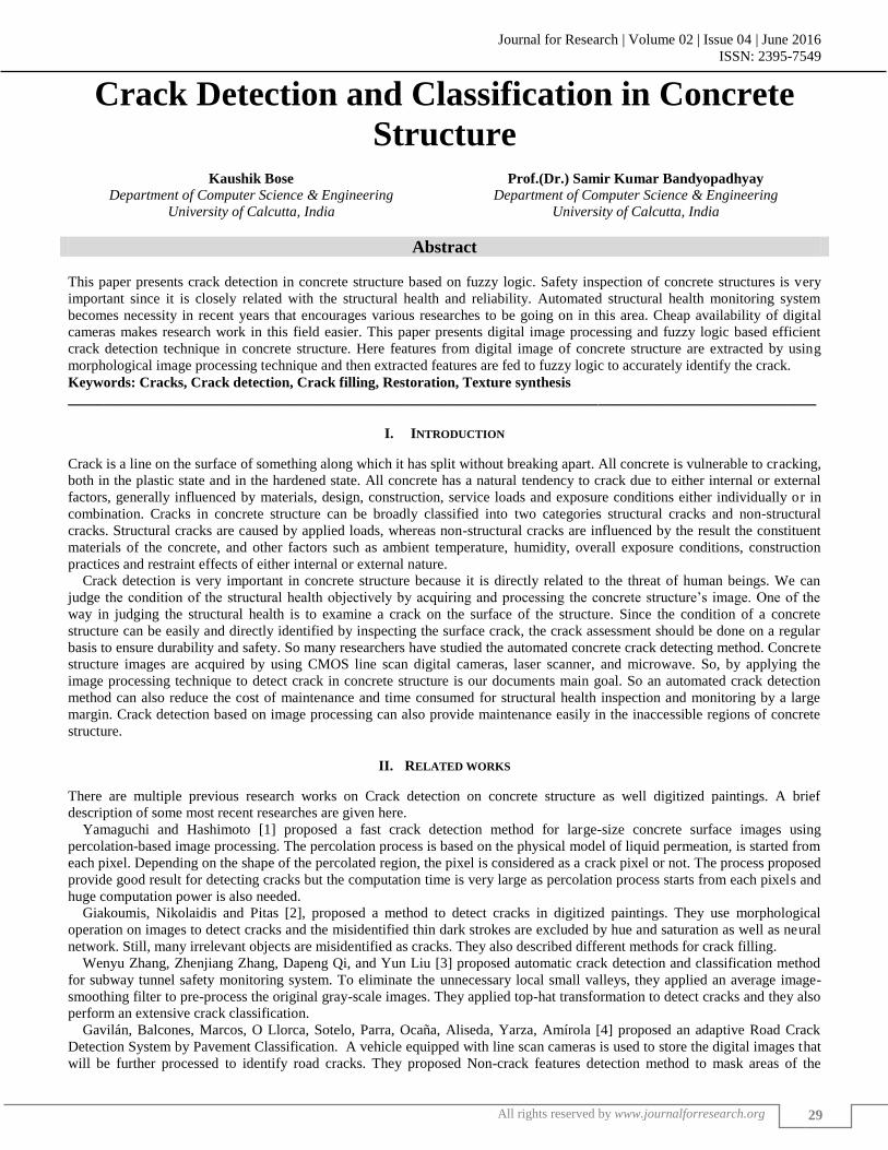
Journal for Research | Volume 02 | Issue 04 | June 2016
ISSN: 2395-7549
All rights reserved by www.journalforresearch.org
29
Crack Detection and Classification in Concrete
Structure
Kaushik Bose Prof.(Dr.) Samir Kumar Bandyopadhyay
Department of Computer Science & Engineering Department of Computer Science & Engineering
University of Calcutta, India University of Calcutta, India
Abstract
This paper presents crack detection in concrete structure based on fuzzy logic. Safety inspection of concrete structures is very
important since it is closely related with the structural health and reliability. Automated structural health monitoring system
becomes necessity in recent years that encourages various researches to be going on in this area. Cheap availability of digital
cameras makes research work in this field easier. This paper presents digital image processing and fuzzy logic based efficient
crack detection technique in concrete structure. Here features from digital image of concrete structure are extracted by using
morphological image processing technique and then extracted features are fed to fuzzy logic to accurately identify the crack.
Keywords: Cracks, Crack detection, Crack filling, Restoration, Texture synthesis
_______________________________________________________________________________________________________
I. INTRODUCTION
Crack is a line on the surface of something along which it has split without breaking apart. All concrete is vulnerable to cracking,
both in the plastic state and in the hardened state. All concrete has a natural tendency to crack due to either internal or external
factors, generally influenced by materials, design, construction, service loads and exposure conditions either individually or in
combination. Cracks in concrete structure can be broadly classified into two categories structural cracks and non-structural
cracks. Structural cracks are caused by applied loads, whereas non-structural cracks are influenced by the result the constituent
materials of the concrete, and other factors such as ambient temperature, humidity, overall exposure conditions, construction
practices and restraint effects of either internal or external nature.
Crack detection is very important in concrete structure because it is directly related to the threat of human beings. We can
judge the condition of the structural health objectively by acquiring and processing the concrete structure‘s image. One of the
way in judging the structural health is to examine a crack on the surface of the structure. Since the condition of a concrete
structure can be easily and directly identified by inspecting the surface crack, the crack assessment should be done on a regular
basis to ensure durability and safety. So many researchers have studied the automated concrete crack detecting method. Concrete
structure images are acquired by using CMOS line scan digital cameras, laser scanner, and microwave. So, by applying the
image processing technique to detect crack in concrete structure is our documents main goal. So an automated crack detection
method can also reduce the cost of maintenance and time consumed for structural health inspection and monitoring by a large
margin. Crack detection based on image processing can also provide maintenance easily in the inaccessible regions of concrete
structure.
II. RELATED WORKS
There are multiple previous research works on Crack detection on concrete structure as well digitized paintings. A brief
description of some most recent researches are given here.
Yamaguchi and Hashimoto [1] proposed a fast crack detection method for large-size concrete surface images using
percolation-based image processing. The percolation process is based on the physical model of liquid permeation, is started from
each pixel. Depending on the shape of the percolated region, the pixel is considered as a crack pixel or not. The process proposed
provide good result for detecting cracks but the computation time is very large as percolation process starts from each pixels and
huge computation power is also needed.
Giakoumis, Nikolaidis and Pitas [2], proposed a method to detect cracks in digitized paintings. They use morphological
operation on images to detect cracks and the misidentified thin dark strokes are excluded by hue and saturation as well as neural
network. Still, many irrelevant objects are misidentified as cracks. They also described different methods for crack filling.
Wenyu Zhang, Zhenjiang Zhang, Dapeng Qi, and Yun Liu [3] proposed automatic crack detection and classification method
for subway tunnel safety monitoring system. To eliminate the unnecessary local small valleys, they applied an average image-
smoothing filter to pre-process the original gray-scale images. They applied top-hat transformation to detect cracks and they also
perform an extensive crack classification.
Gavilán, Balcones, Marcos, O Llorca, Sotelo, Parra, Ocaña, Aliseda, Yarza, Amírola [4] proposed an adaptive Road Crack
Detection System by Pavement Classification. A vehicle equipped with line scan cameras is used to store the digital images that
will be further processed to identify road cracks. They proposed Non-crack features detection method to mask areas of the

Crack Detection and Classification in Concrete Structure (J4R/ Volume 02 / Issue 04 / 07)
All rights reserved by www.journalforresearch.org
30
images with joints, sealed cracks and white painting that usually generate false positive cracking and provide a seed-based
approach to deal with road crack detection combining Multiple Directional Non-Minimum Suppression (MDNMS) with a
symmetry check. The system performs well for road crack detection.
Miss Vidya Vinayak Khandare and Prof. Mr. Nitin B. Sambre [5] proposed a crack detection and removal method in digitized
painting. The cracks are identified and detected by Gabor which is an integrated methodology for removal of cracks. First, they
filter the selected crack image using 8 differently oriented Gabor filters for the purpose of feature extraction to represent a crack
network from sets of local orientation features. They used resultant features for crack filling with median filter and weighted
median filter. Their methodology has been shown to perform well on digitized paintings suffering from cracks.
Gajanan K.Choudhary and Sayan Dey [6] proposed crack detection in concrete surface using image processing based on fuzzy
logic and neural network. They use feature extraction that is crack like regions detection based on edge detection procedure and
then apply fuzzy and neural network approach to classify crack and noise.
Fujita et al. [7] proposed a method which involves image pre-processing using subtraction of smooth images and a hessian
matrix based line filter then cracks are detected by applying a threshold operation.
III. PROPOSED METHOD
The total procedure of crack detection and classification consists of five steps as shown in figure 1
Fig. 1: Flowchart of the proposed method
Image Acquisition: A.
Images of concrete structure can be acquired by using CMOS line scan digital cameras. For image acquisition purpose a machine
that can roll on with built in cameras can be used such that when machine moves on the concrete surface it captures images for
detection purpose. In case of huge concrete structure or historical buildings of concrete, picture taken from satellite can also be
used.
In our research work total 30 images are used and most of them were downloaded from different sources by searching internet.
In the process of image collection for our work we only considered the images that do not have any other object other than
concrete structure because if images contain other objects then that object can be considered as crack. Also cracks has to be at
least visible by human eye though there may be huge amount of noises else no crack will be detected by this method.
Image Pre-processing: B.
The original image may contain some useless details that can be removed by using some basic image processing that we consider
here as image pre-processing. Various steps of image pre-processing used here, all of which are given below.
Image Resizing: 1)
First all the images are resized to the width of 512 pixels and the height was adjusted such that original image aspect ratio
maintained to maintain uniformity of the system such that all images have same criteria for crack detection procedure.
Maintaining uniformity is necessary in image classification stage where fuzzy logic is used.
RGB to Grayscale Image Conversion: 2)
For pre-processing of image, the RGB image first of all is converted into grayscale image which makes the process much easier,
because here we need not to maintain three matrixes for three colour component red(R), green(G), Blue(B). In grayscale image
each pixel is represented by a single value between 0 to 255. This value is called luminance or intensity of that pixel. The
standard NTSC conversion formula that is used for calculating the effective luminance of a pixel:
Image Smoothing: 3)
Original image may contain some useless details. Images can also be affected by some extent of noise, that is unexplained
variation in data disturbances in image intensity which are either uninterpretable or not of interest. Simply by applying linear
averaging filter for image smoothing a huge percentage of these unintended or useless details and noise can be removed.
Crack Detection and Classification in Concrete Structure (J4R/ Volume 02 / Issue 04 / 07)
All rights reserved by www.journalforresearch.org
31
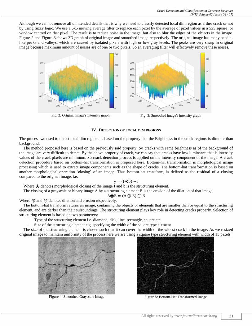
Although we cannot remove all unintended details that is why we need to classify detected local dim region as either crack or not
by using fuzzy logic. We use a 5x5 moving average filter to replace each pixel by the average of pixel values in a 5x5 square, or
window centred on that pixel. The result is to reduce noise in the image, but also to blur the edges of the objects in the image.
Figure-2 and Figure-3 shows 3D graph of original image and smoothed image respectively. The original image has many needle-
like peaks and valleys, which are caused by isolated pixels with high or low gray levels. The peaks are very sharp in original
image because maximum amount of noises are of one or two pixels. So an averaging filter will effectively remove these noises.
Fig. 2: Original image's intensity graph
Fig. 3: Smoothed image's intensity graph
IV. DETECTION OF LOCAL DIM REGIONS
The process we used to detect local dim regions is based on the property that the Brightness in the crack regions is dimmer than
background.
The method proposed here is based on the previously said property. So cracks with same brightness as of the background of
the image are very difficult to detect. By the above property of crack, we can say that cracks have low luminance that is intensity
values of the crack pixels are minimum. So crack detection process is applied on the intensity component of the image. A crack
detection procedure based on bottom-hat transformation is proposed here. Bottom-hat transformation is morphological image
processing which is used to extract image components such as the shape of cracks. The bottom-hat transformation is based on
another morphological operation ‗closing‘ of an image. Thus bottom-hat transform, is defined as the residual of a closing
compared to the original image, i.e.
( ) Where denotes morphological closing of the image f and b is the structuring element.
The closing of a grayscale or binary image A by a structuring element B is the erosion of the dilation of that image,
( )
Where and denotes dilation and erosion respectively.
The bottom-hat transform returns an image, containing the objects or elements that are smaller than or equal to the structuring
element, and are darker than their surroundings. The structuring element plays key role in detecting cracks properly. Selection of
structuring element is based on two parameters:
Type of the structuring element i.e. diamond, disk, line, rectangle, square etc.
Size of the structuring element e.g. specifying the width of the square type element
The size of the structuring element is chosen such that it can cover the width of the widest crack in the image. As we resized
original image to maintain uniformity of the process here we are using a square type structuring element with width of 15 pixels.
Figure 4: Smoothed Grayscale Image
Figure 5: Bottom-Hat Transformed Image

Crack Detection and Classification in Concrete Structure (J4R/ Volume 02 / Issue 04 / 07)
All rights reserved by www.journalforresearch.org
32
V. CRACK SEPARATION
The output of the bottom-hat transform is a grayscale image where pixels with higher intensity value are considered as crack
pixels. So to separate crack from rest of the image thresholding operation on bottom-hat transformed grayscale image in done.
For thresholding operation is done based one the global image threshold level value using Otsu's method which chooses the
threshold value to minimize the intra-class variance of the thresholded black and white pixels. This turns out to be the same as
maximizing the between-class variance. Operates directly on the graylevel histogram, so it‘s fast (once the histogram is
computed). The output image replaces all pixels in the input image with luminance greater than threshold level obtained by using
Otsu‘s [8] method with the value 1 (white) and replaces all other pixels with the value 0 (black).
OTSU: ASSUMPTIONS: A.
Histogram (and the image) is bimodal.
No use of spatial coherence, nor any other notion of object structure.
Assumes stationary statistics, but can be modified to be locally adaptive. (exercises)
Assumes uniform illumination (implicitly), so the bimodal brightness behavior arises from object appearance differences only.
The weighted within-class variance is:
Where the class probabilities are estimated as:
And the class means are given by:
Finally, the individual class variances are:
Now, we could actually stop here. All we need to do is just run through the full range of t values [1,256] and pick the value
that minimizes .
But the relationship between the within-class and between-class variances can be exploited to generate a recursion relation that
permits a much faster calculation.
After some algebra, we can express the total variance as:
Since the total is constant and independent of t, the effect of changing the threshold is merely to move the contributions of the
two terms back and forth.
Thus Otsu shows us that minimizing the intra-class variance is the same as maximizing inter-class variance.
Figure 6: Bottom-Hat Thresholded image
w
2(t) q
1(t)
1
2(t) q
2(t)
2
2(t)
1
2( t ) [i
1(t )]
2 P( i)
q1(t )i1
t
2
2( t ) [i
2(t )]
2 P (i)
q2(t )i t 1
I

Crack Detection and Classification in Concrete Structure (J4R/ Volume 02 / Issue 04 / 07)
All rights reserved by www.journalforresearch.org
33
Crack Identification: B.
After the thresholding operation in the previous section we are able to remove most of the miss-identified regions but still some
irrelevant unintended image details which we call as noise are preserved as cracks. All the connected regions of the image are
considered as an object. So an object can be either crack or noise. So crack identification is very important and final step of our
process. This crack identification consists of three stages:
Detection of objects and its necessary properties
Creation of Fuzzy Model and finding fuzzy output value for each object
Convert the fuzzy output value to crisp output value
Detection of Objects with its Necessary Properties: C.
Objects of an image are basically connected components found in the binary image. Connected-component labelling is used to
detect connected regions in binary digital image. In image processing and image recognition, pixel connectivity is the way in
which pixels in 2-dimensional images relate to their neighbours. Here we use 8-connected neighbourhood technique to find
connected components in an image. In an 8-connected neighbourhood, all of the pixels that touch the pixel of interest are
considered, including those on the diagonals. This means that if two adjoining pixels are on, they are part of the same object,
regardless of whether they are connected along the horizontal, vertical, or diagonal direction.
Fig. 7: A 8-Connected Neighbourhood model
Fig. 8: Image With Identified Objects
Now we need to identify some object properties which will form the basis to the fuzzy model of crack detection. So the
properties must be chosen such that they all together provide substantial difference between crack and noise. So only one or two
properties may not be sufficient to differentiate between crack or noise that all the three properties need to be considered
together. In our model we use three properties to detect crack which are given below:
Area: 1)
Area is a scalar value which specifies total number of pixels in a particular object. Area is chosen because in general number of
pixels in crack i.e. area is higher than noise.
Ratio of Major and Minor Axis: 2)
‗MajorAxisLength‘ is a scalar value that specifies the length (in pixels) of the major axis of the ellipse that has the same
normalized second central moments as the region where as ‗MinorAxisLength‘ is a scalar value that specifies the length (in
pixels) of the minor axis of the ellipse that has the same normalized second central moments as the region. We use the ratio of
‗MajorAxisLength‘ and ‗MinorAxisLength‘. This property is chosen such that in general cracks elongated structure so the ratio
of major and minor axes lengths should be higher compared to noise.
Ratio of Boundingbox-area and object-area: 3)
'Bounding Box' is the smallest rectangle containing the object. So the bounding box-area is the scaler value which specifies the
number of pixel can have in that bounding box, we will get this easily by multiplying the width and height of the bounding box.
Object-area is the area specified above that is the number of pixel in an object. We use this property because though in general
cracks are elongated structure but in some cases cracks may have branches in that cases ratio of major and minor axes will be
lower and also in some cases noises can also have higher area, so in these situation ratio of boundingbox-area and object-area
will be higher in case of crack than noise.
Fuzzy Logic Model: D.
Fuzzy logic, introduced by L. A. Zadeh [9] in 1965. Fuzzy logic had however been studied since the 1920s, as infinite-valued
logic—notably by Łukasiewicz and Tarski. Over the past few decades, fuzzy logic has been used in a wide range of problem
domains such as process control, management and decision making, operations research, economies and, for this paper the most
important, pattern recognition and classification. The natural description of problems, in linguistic terms, rather than in terms of
relationships between precise numerical values is the major advantage of this theory.

Crack Detection and Classification in Concrete Structure (J4R/ Volume 02 / Issue 04 / 07)
All rights reserved by www.journalforresearch.org
34
Fuzzy logic is almost synonymous with the theory of fuzzy sets, a theory which relates to classes of objects with un-sharp
boundaries in which membership is a matter of degree that is a fuzzy set is a set without a crisp, clearly defined boundary. It can
contain elements with only a partial degree of membership. Fuzzy logic includes 0 and 1 as extreme cases of truth (or "fact") but
also includes the various states of truth in between so that, for example, fuzzy logic also permits in-between values like 0.4 and
0.56 etc.
We use MATLAB‘s fuzzy logic toolbox to create Mamdani-type fuzzy logic model to classify crack and noise. Mamdani's
fuzzy inference method expects the output membership functions to be fuzzy sets. After the aggregation process, there is a fuzzy
set for each output variable that needs defuzzification. For our fuzzy logic model the input variables are ‗Area‘, ‗Major-Minor
Axes Ratio‘ and ‗Bounding box Area-Object Area Ratio‘. So each object‘s these three properties are feed to fuzzy model to get
fuzzy output. The range of each variable is given in the table. The input variables ‗Area‘, ‗Major-Minor Axes Ratio‘ and
‗Bounding box Area-Object Area Ratio‘ have three, two and two subsets respectively where the output has two subsets. Each
subset needs one single membership function. The membership functions used here for all the input variables and output variable
are trapezoidal-type. Trapezoidal membership function is defined by a lower limit a, an upper limit d, a lower support limit b,
and an upper support limit c, where a < b < c < d.
Fig. 9: Trapezoidal membership Function Representation
Table – 1
Membership function values For the fuzzy logic Model
Variables Variable Range Membership Function Trapezoidal Value
a b c d
‘Area’ [0-20000]
Low 0 0 200 400
Medium 200 400 600 2000
High 600 20000 20000 20000
‘Major-Minor Axes Ratio’ [0-200] Low 0 0 4.5 5.5
High 4.5 5.5 200 200
‘BoundingboxArea-ObjectArea Ratio’ [0-500] Low 0 0 5 6
High 5 6 500 500
‘Output’ [0-1] Noise 0 0 0.45 0.55
Crack 0.45 0.55 1 1
Fuzzy sets and fuzzy operators are the subjects and verbs of fuzzy logics. If x is A Then y is B where x and y are fuzzy
variables and A and B are fuzzy values. The if-part of the rule "x is A" is called the antecedent or premise, while the then-part of
the rule "y is B" is called the consequent or conclusion. Statements in the antecedent (or consequent) parts of the rules may well
involve fuzzy logical connectives such as ‗AND ‗OR‘ and ‗NOT‘. For our Fuzzy model we only use ‗AND‘ operator. The rules
have been given in table-2. Table – 2
Fuzzy Inference Rule Set
Rule No. Area Major-Minor Axes Ratio BoundingboxArea-ObjectArea Ratio Output
1 High High Crack
2 High Low High Crack
3 Medium High Crack
4 Medium Low High Crack
5 Low High Noise
6 Low High Noise

Crack Detection and Classification in Concrete Structure (J4R/ Volume 02 / Issue 04 / 07)
All rights reserved by www.journalforresearch.org
35
Fuzzy output value to crisp output value Conversion
As we are using Mamdani's fuzzy inference method for our system we will get fuzzy output value that is output value can be
any value from 0 to 1 this means output value can be fraction type. But we need crisp output that is 1 for crack and 0 for noise.
For this defuzzification process we need a threshold value such that below that value output means objet is noise else crack. To
obtain the threshold value we need to consider two criteria.
We want to increase the detection rate to 1 and decrease detection error to 0. But Detection Rate and Detection error are
disproportional to each other. But we need to give priority to high detection rate over reduced detection error because if some
cracks are not detected it may bring casualties for human being. So taking both the criteria in concern we are getting best
performance at threshold value of 0.74 which gives 99.2% accuracy in detection rate with 1.95% detection error. Now one thing
we must be consider that if some very small portion of a bigger crack is not detected we are neglecting this because as main
crack is detected then it will go for the manual inspection to civil engineering department.
Algorithm: E.
1) STEP 1: Read the image.
2) STEP 2: If the image is not grayscale than convert it to grayscale image. Resize the image to maintain uniformity and
perform image smoothing by applying linear averaging filter.
3) STEP 3: Define the structural element by specifying structural element type and size. In most of the cases square type
structural element is beneficial for crack detection and defines its size approximately as the size of the widest crack width.
4) STEP 4: Perform the bottom-hat transformation using the defined structural element in step-3.
5) STEP 5: Compute the global image threshold level value using Otsu‘s [8] method which chooses the threshold value to
minimize the intra-class variance of the thresholded black and white pixels.
6) STEP 6: Convert the bottom-hat transformed image into binary image by thresholding using the threshold level value from
step-5.
7) STEP 7: Identify each objects that is each connected component in the image and find its properties like ‗Area‘, ‗Major-
Minor Axes Ratio‘ and ‗BoundingboxArea-ObjectArea Ratio‘.
8) STEP 8: Use the properties stated in step-7 as the input variables to create a fuzzy model based on membership function
value shown in table-1 and ‗if-then-else‘ inference rule set in table-2.
9) STEP 9: Feed each objects properties to the fuzzy model created in step-8 to get fuzzy output.
10) STEP 10: Convert to fuzzy output to crisp output based on the threshold value 0.74 to identify which is crack and which is
noise.
VI. EXPERIMENTAL RESULTS
Result Set 1: A.
Fig. 10: Original Image
Fig. 11: Grayscale Image

Crack Detection and Classification in Concrete Structure (J4R/ Volume 02 / Issue 04 / 07)
All rights reserved by www.journalforresearch.org
36
Fig. 12: Smoothed Grayscale image
Fig. 13: Bottom-Hat Transformed image
Fig. 14: Bottom-Hat Thresholded Image
Fig. 15: Image With Identified Objects
Fig. 16: Image with Identified Cracks
Result Set -2: B.
Fig. 17: Original Image
Fig. 18: Grayscale Image

Crack Detection and Classification in Concrete Structure (J4R/ Volume 02 / Issue 04 / 07)
All rights reserved by www.journalforresearch.org
37
Fig. 19: Smoothed Grayscale image
Fig. 20: Bottom-Hat Transformed image
Fig. 21: Bottom-Hat Thresholded Image
Fig. 22: Image With Identified Objects
Fig. 23: Image with Identified Cracks
VII. CONCLUSIONS
This paper presents a crack detection and classification technique for concrete structure based on the images of the concrete
surface. Images are analyzed by applying several images processing technique and finally crack classification is done by
applying fuzzy logic. This method of crack detection and classification can also be applied on several different situations other
than concrete surface like cracks on paintings. In the image classification process, we are not considering whole image at a time
to classify all the cracks in the image instead we apply object approach that is each connected component in the image has been
checked individually, by doing this we are getting more accurate result though it is little more time consuming than identifying
all the cracks in the image at a time.
REFERENCES
[1] Yamaguchi, T.; Hashimoto, S. ―Fast crack detection method for large-size concrete surface images using percolation-based image processing‖. Mach. Vis. Appl. 2010, 21, 797–809.
[2] Giakoumis, I.; Nikolaidis, N.; Pitas, I. ―Digital image processing techniques for the detection and removal of cracks in digitized paintings‖. IEEE Trans.
Image Process. 2006, 15, 178–188. [3] Wenyu Zhang; Zhenjiang Zhang; Dapeng Qi; and Yun Liu. ―Automatic Crack Detection and Classification Method for Subway Tunnel Safety
Monitoring‖. Sensors 2014, 14, 19307-19328
[4] Gavilán, M.; Balcones, D.; Marcos, O.; Llorca, D.F.; Sotelo, M.A.; Parra, I.; Ocaña, M.; Aliseda, P.; Yarza, P.; Amírola, A. ―Adaptive Road Crack Detection System by Pavement Classification‖. Sensors 2011, 11, 9628–9657.
[5] Khandare Vidya Vinayak Khandare; Sambre Nitin B. ―Detection & Removal of Cracks in Digitized Paintings Based on Image Processing‖. International Journal of Engineering Research & Technology (IJERT)2014 ISSN: 2278-0181 Vol. 3 Issue 1, 2014

Crack Detection and Classification in Concrete Structure (J4R/ Volume 02 / Issue 04 / 07)
All rights reserved by www.journalforresearch.org
38
[6] Gajanan K. Choudhary and Sayan Dey. ―Crack Detection in Concrete Surfaces using Image Processing, Fuzzy Logic, and Neural Networks‖. 2012 IEEE
fifth International Conference on Advanced Computational Intelligence(ICACI) October 18-20, 2012
[7] Byoung Jik Lee, and Hosin ―David‖ Lee, ―Position-Invariant Neural Network for Digital Pavement Crack Analysis,‖ Computer-Aided Civil and
Infrastructure Engineering, Volume 19, Issue 2, pages 105–118, March 2004.
[8] N.Otsu (1979) ―A threshold selection method form gray-level histograms‖. Proceedings of the 1986 IEEE Transactions Systems, Man and Cybernetics, Vol.9, No. 1, 62-66
[9] L. A. Zadeh, "Fuzzy sets," Information and Control, vol. 8, pp. 338-353, 1965.
[10] Y. Fujita, and Y. Hamamoto, ―A robust method for automatically detecting cracks on noisy concrete surfaces,‖ Next-Generation Applied Intelligence. 22nd International Conference on Industrial, Engineering and Other Applications of Applied Intelligent Systems IEA/AIE 2009, pp. 76–85, June 2009, Tainan,
Taiwan.
[11] Rafael C. Gonzalez, Richard E. Woods and Steven L.Eddins ―Digital Image Processing Using Matlab,‖ Pearson Education, Second Impression,2007. [12] MATLAB Functions in Fuzzy Logic Toolbox, www.mathworks.in/help/fuzzy/functionlist.html