Embed Size (px)
DESCRIPTION
Cognitive wireless mesh
Citation preview

168 IEEE JOURNAL ON SELECTED AREAS IN COMMUNICATIONS, VOL. 26, NO. 1, JANUARY 2008
Cognitive Wireless Mesh Networks with DynamicSpectrum Access
Kaushik R. Chowdhury, Student Member, IEEE, and Ian F. Akyildiz, Fellow, IEEE
Abstract—Wireless Mesh Networks (WMNs) are envisaged toextend Internet access and other networking services in personal,local, campus, and metropolitan areas. Mesh routers (MR) formthe connectivity backbone while performing the dual tasks ofpacket forwarding as well as providing network access to themesh clients. However, the performance of such networks is lim-ited by traffic congestion, as only limited bandwidth is availablefor supporting the large number of nodes in close proximity. Thisproblem can be alleviated by the cognitive radio paradigm thataims at devising spectrum sensing and management techniques,thereby allowing radios to intelligently locate and use frequenciesother than those in the 2.4 GHz ISM band. These promisingtechnologies are integrated in our proposed COgnitive MeshNETwork (COMNET) algorithmic framework, thus realizing anintelligent frequency-shifting self-managed mesh network. Thecontribution of this paper is threefold: (1) A new approach forspectrum sensing is devised without any change to the workingof existing de facto mesh protocols. (2) An analytical model isproposed that allows MRs to estimate the power in a givenchannel and location due to neighboring wireless LAN traffic,thus creating a virtual map in space and frequency domains.(3) These models are used to formulate the task of channelassignment within the mesh network as an optimization problem,which is solved in a decentralized manner. Our analytical modelsare validated through simulation study, and results reveal thebenefits of load sharing by adopting unused frequencies for WMNtraffic.
Index Terms—Analytical Modeling, Cognitive Radio, SpectrumSensing, Spectrum Sharing, Wireless Mesh Networks
I. INTRODUCTION
W IRELESS Mesh Networks (WMNs) are envisaged tobe a key technology that allows ubiquitous connectiv-
ity to the end user. A typical WMN consists of mesh routers(MRs) forming the backbone of the network, interconnectedin an ad-hoc fashion. Each MR can be considered as an accesspoint serving a number of users or mesh clients (MCs) [2].The MCs could be mobile users, stationary workstations orlaptops that exchange data over the Internet. They direct theirtraffic to their respective MRs, which then forwards it overthe backbone, in a multi-hop manner, to reach the gatewaythat links to the Internet. Thus, WMNs promise communitywide network access at affordable monetary and infrastructurecosts.
While WMNs enhance performance with flexible networkarchitectures, easy deployment and configuration, and faulttolerance, the high density of nodes may lower the network
Manuscript received March 1, 2007; revised August 24, 2007.Kaushik R. Chowdhury and Ian F. Akyildiz are with the Broadband
Wireless Networking Laboratory, School of Electrical and Computer Engi-neering, Georgia Institute of Technology, Atlanta, GA, 30332 USA (e-mail:kaushikc,[email protected]).
Digital Object Identifier 10.1109/JSAC.2008.080115.
capacity. From the analytical results in [11], it follows thatthe throughput capacity per node reduces significantly whenthe node density increases. In addition, the 2.4 GHz ISMband currently used by mesh based architectures is shared bymost single access-point based Wireless Local Area Network(WLAN) devices, Bluetooth [26], radiation from microwaveovens, amongst others. Urban areas are affected most by thischannel congestion [13], and thus there is a strong motivationto identify unused portions of the spectrum which can be usedto carry the mesh network traffic. This effectively reducesthe node density per transmission channel, thus improvingthroughput and can be attractive as lower frequencies, espe-cially in the MHz range, exhibit better propagation character-istics. In this work, we use the terminology secondary band forthe ISM band and secondary users for mesh network devicesoperating in that band.
The need for intelligent and network aware spectrum selec-tion can be addressed by the recently emerging cognitive radioparadigm. These radios may decide transmission parameterssuch as channel, power, modulation type, and transmissionrate through local coordination based on their perception ofthe surrounding environment [1]. The Federal Communica-tions Commission (FCC) has encouraged work in spectrumsharing issues by initiating steps to free up unused portionsof the spectrum and advocating the use of digital televisionover its analog counterpart. This may free up bandwidthin the 54 − 72 MHz, 76 − 88 MHz, 174 − 216 MHz, and470− 806 MHz bands [7]. We consider the more general sce-nario, in which the entire frequency ranges are not completelyvacated, but may experience occasional transmissions by thelicensed users. Also, certain frequencies may be reserved forspecial communication needs, such as emergency services andmilitary, which may see a burst of network activity followedby a long duration for which the channel lies unused. We referto these bands as primary bands and the licensed operators inthem as primary users in the subsequent discussion.
In this paper we explore ways in which secondary usersequipped with tunable radios may share the primary band,thus coexisting with the licensed users of that band. It isimperative that primary users in these bands have priorityin communication and their operation must not be hinderedby spectrum sharing techniques. Thus, the key challengesthat must be addressed include identifying which portionsof the spectrum are free for use, resolving contentions withthe licensed users operating in those frequencies and loadbalancing over the entire available spectrum.
Our proposed COgnitive wireless Mesh NETwork (COM-NET) suite of spectrum sensing and sharing algorithms takes
0733-8716/08/$25.00 c© 2008 IEEE

CHOWDHURY and AKYILDIZ: COGNITIVE WIRELESS MESH NETWORKS WITH DYNAMIC SPECTRUM ACCESS 169
Fig. 1. Example mesh architecture with mesh routers (MRs) and meshclients (MCs) under them. The mesh components are located in a spatiallyoverlapped region with primary transmitter stations.
the first step in leveraging the benefits of cognitive radiotechnology in the area of WMNs. We adhere to the standardassumptions of WMNs [2] in terms of the nature and numberof available interfaces at each mesh node, save the additionalability to transmit at either the primary or secondary bandat a given time. Thus, our solution can be easily integratedinto an existing mesh scenario with little change to thedeployed infrastructure. Specifically, the contributions madein this paper are as follows:
• We propose a scheme that allows MCs, equipped with asingle tunable transceiver, to monitor the primary chan-nels while continuing operation in the secondary band.
• We devise a theoretical framework for identifying pri-mary transmitter frequencies through time domain sam-pling. We achieve this by formulating the task of sensingas a linear programming problem based on receivedsignal strength values on any given channel.
• While sensing is used to locate empty portions of thespectrum, it is necessary to evaluate the additional powerinjected before actually shifting the secondary users in theprimary band. For this, we propose an analytical modelof estimating interference caused at any arbitrary locationand frequency due to the mesh traffic.
• We formulate the task of channel assignment as anoptimization problem that is solved at each MR using theempty channels identified through sensing and analyticalpower estimations for the mesh operation.
The rest of this paper is organized as follows. In Section II,we list our assumptions and give an overview of the workingof our proposed COMNET algorithms. In Section III, we layout our analytical framework for spectrum sensing. Section IVpresents our analytical model for calculating the interferencedue to neighboring mesh activity and Section V proposes aspectrum sharing algorithm based on this model. Our modelsare thoroughly evaluated in Section VI. Section VII describesthe related work in this area and Section VIII discussessome issues related to our approach. Finally, we conclude our
work in Section IX while pointing out directions for furtherresearch.
II. ARCHITECTURE AND SYSTEM OPERATION
The COMNET design aims to embed intelligent spectrumsensing capability in a standard mesh scenario without ad-vanced hardware/software techniques such as (i) widebandfilters that can sense bandwidth of several hundreds of MHzand (ii) the use of a priori knowledge of the sender’s trans-mission content [1]. While these advancements, if present, willundoubtedly enhance cognitive radio operation, our aim is touse off-the-shelf components that are commercially available,like the legacy IEEE 802.11 WLAN cards operating in thesecondary band. We now explain the mesh architecture thatis used by our algorithms followed by an explanation of theworking of the system.
A. Architecture Description
As seen in Figure 1, a given mesh router (MR) has severalclients (MCs) under it and these jointly form a cluster. Thestandard mesh network architecture consists of several suchclusters, and all uplink/downlink flows are directed fromthe individual MCs towards its own MR and forwarded ina multihop fashion towards the gateway connected to theInternet. Each cluster can be visualized to be a single WLANsystem, with the MR as the access point and the MCs asnodes served by it. Peer to peer communications between meshclients belonging to different clusters may also be carried outwithout passing through the gateway.
Each MR and MC is equipped with a single IEEE 802.11 bbased transceiver. Using typical assumptions of a frequencyagile radio [1], this is tunable to any one of the allowedfrequencies (channels) in the primary or the secondary band ata given time. This reduces the cost and complexity typicallyassociated with two-transceiver nodes. In addition, the MRsare considered to be resource rich and can undertake com-putational overheads. MR-MR multi-hop links are achievedthrough out of band communication on a different channel,and is not subject to contention from the remaining nodes[2]. While the number of MCs in a cluster may changedynamically, each MR has a fixed location that is known toall the other MRs in the mesh system.
We assume the primary transmitters to be stationary ra-dio/television towers in this work, and shall henceforth referto them as primary stations. There is no restriction on themobility of the primary receivers. As an indicative primaryband, we consider 16 channels with 5 MHz spacing, andranging from 712 − 787 MHz with similar transmission andpower mask restrictions1 as the ISM band. These valuescan be easily changed to suit any other band and networkrequirements in a specific primary user system.
Our algorithm requires an MC to calculate its distancefrom the primary stations when required. This cannot beaccomplished by received signal strength (RSSI) calculationsbased on primary station power, as the received power in
1FCC imposed constraint on the leakage power as a function of distancefrom the center transmission frequency

170 IEEE JOURNAL ON SELECTED AREAS IN COMMUNICATIONS, VOL. 26, NO. 1, JANUARY 2008
Fig. 2. The radio may switch to the primary channel for the duration of thepacket transfer during the freeze duration, if it is not the intended recipient.
that band is a summation of several different transmitterswhose frequencies are unknown. Instead, we use localizationtechniques like triangulation in the ISM band by tuning insuccession to the MC’s own channel and that of a neighboringcluster. As all occupied ISM channels and locations of thefixed MRs are known in advance, unlike in the primary band,the interference effects from other MRs can be accounted forin the calculation.
B. System Operation
We now summarize the working of the system with anexample scenario shown in Figure 1. The MCs periodicallytune to a pre-decided channel in the primary band and sensethe total received power for a short duration. These sensedvalues are communicated by the MCs, along with their dis-tances from the primary stations, to the MRs of their respectiveclusters by piggybacking over data packets. However, in theevent that only peer to peer communication exists in thenetwork without involving the gateway, MRs need to sendtheir statistics specially at a pre-decided frequency to it. Thus,MCs x′, y′ and z′ in cluster C1 measure the received poweron channel 9, say, and report it back to their MR. Each MR ofa cluster then uses our proposed sensing solution, explainedin Section III, to identify the primary station frequencies.
This information about the detected primary frequencies ata cluster is included in packets directed towards the gate-way from the MRs, and updated in a centralized databaseat the gateway. This database also contains the numberof active transmitting nodes in a cluster, which is eas-ily obtained as every traffic stream from a given MC ofa cluster passes through the gateway. The data tuple inthe form of 〈 cluster ID, primary frequenciesdetected, number of nodes〉 for all the clusters inthe network is included at regular intervals in the downstreampackets from the gateway. This mechanism allows dissemi-nation of the primary station data to all the clusters in thenetwork, i.e., C1, C2 and C3 in our example, without the useof additional packets or delays.
Based on these received values and our analytical modelpresented in Section IV, each MR can then calculate an ap-proximate measure of interference introduced by its own clus-ter, as well as the others, at any arbitrary geographical locationand channel. As each MR has the same input conditions and is
TABLE ISIMULATION PARAMETERS FOR THE 3 TRANSMITTER SCENARIO
Primary Tx Distance from x′ Channel Frequency(m) (MHz)
1 230 9 752
2 230 9 752
3 500 13 772
subjected to the same constraints, they independently solve anoptimization problem of deciding which of them should shifttheir operation in the primary band and the frequency that maybe used in that band. Thus, clusters as a whole remain in theISM band or switch to the primary band so that the networkload is balanced, and the primary band interference is withinallowed limits. In the event that C1 is identified as the clusterthat must shift to the primary band, the MR and x′, y′, z′
under it, must together change to a new frequency returned asa solution to the optimization problem. We next describe theproblem of spectrum sensing, i.e., identifying the frequenciescurrently being used by primary stations, so that they may beavoided when a device shifts into the primary band.
III. SPECTRUM SENSING
Our proposed method for channel sensing based on timedomain sampling is outlined is Section III-A. We then applyit in centralized and distributed approaches in Sections III-Band III-C respectively.
A. Use of the backoff interval for channel sensing
At the physical layer (PHY), the IEEE 802.11 standard [25]provides a backoff timer that chooses a random number, r, in[0, CW ], where CW stands for contention window. The nodesets the timer to the value 20 µs× r and counts down to zeroas shown in Figure 2 after the completion of the time givenby the Distributed Inter Frame Spacing (DIFS) [25]. Now,during this countdown interval, the channel is still sensed bythe radio. If it is found busy at any particular slot, the backoffcounter is frozen for the duration that the channel is found tobe occupied. In our approach, the MC decodes the header atthe MAC layer while the channel is still sensed busy by thePHY. If it is not the intended recipient of the packet, it doesnot need to monitor the channel any further for the durationspecified in the header. The MC now switches to the primarychannel for sensing the spectrum usage in that band. However,the classical approach of tuning individually to all availablechannels and gathering channel statistics has the followinglimitations:
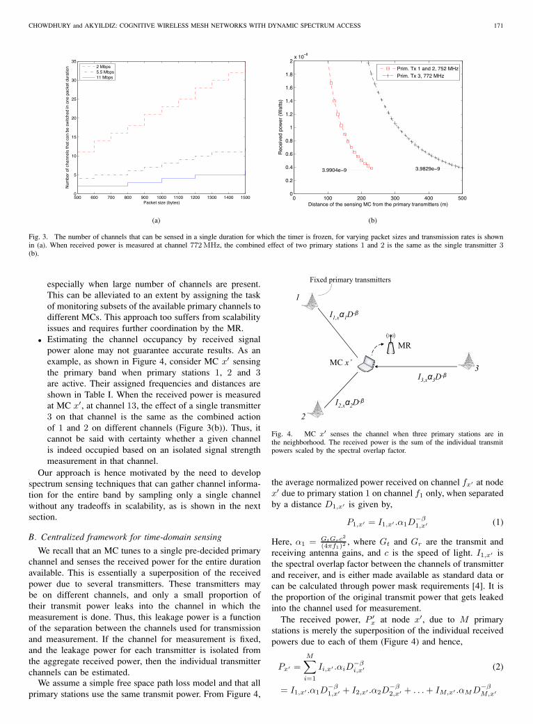
• The short time duration for which the timer is frozenposes an upper limit on the number of channels thatmay be sensed in succession. Assuming the sensing timein each channel is 20 µs, the channel switching timemay range from 100 µs to 200 µs for real devices [14].Figure 3(a) shows the number of channels that may besampled by a single node during one packet transmissiontime. We see that for low packet sizes like 512 bytes andthe typically used 11 Mbps link, less than 3 channels canbe sampled indicating the inadequacy of direct sampling,
CHOWDHURY and AKYILDIZ: COGNITIVE WIRELESS MESH NETWORKS WITH DYNAMIC SPECTRUM ACCESS 171
500 600 700 800 900 1000 1100 1200 1300 1400 15000
5
10
15
20
25
30
35
Packet size (bytes)
Num
ber
of c
hann
els
that
can
be
switc
hed
in o
ne p
acke
t dur
atio
n
2 Mbps5.5 Mbps11 Mbps
(a)
0 100 200 300 400 5000
0.2
0.4
0.6
0.8
1
1.2
1.4
1.6
1.8
2x 10
−8
Distance of the sensing MC from the primary transmitters (m)
Rec
eive
d po
wer
(W
atts
)
Prim. Tx 1 and 2, 752 MHzPrim. Tx 3, 772 MHz
3.9904e−9 3.9829e−9
(b)
Fig. 3. The number of channels that can be sensed in a single duration for which the timer is frozen, for varying packet sizes and transmission rates is shownin (a). When received power is measured at channel 772 MHz, the combined effect of two primary stations 1 and 2 is the same as the single transmitter 3(b).
especially when large number of channels are present.This can be alleviated to an extent by assigning the taskof monitoring subsets of the available primary channels todifferent MCs. This approach too suffers from scalabilityissues and requires further coordination by the MR.
• Estimating the channel occupancy by received signalpower alone may not guarantee accurate results. As anexample, as shown in Figure 4, consider MC x′ sensingthe primary band when primary stations 1, 2 and 3are active. Their assigned frequencies and distances areshown in Table I. When the received power is measuredat MC x′, at channel 13, the effect of a single transmitter3 on that channel is the same as the combined actionof 1 and 2 on different channels (Figure 3(b)). Thus, itcannot be said with certainty whether a given channelis indeed occupied based on an isolated signal strengthmeasurement in that channel.
Our approach is hence motivated by the need to developspectrum sensing techniques that can gather channel informa-tion for the entire band by sampling only a single channelwithout any tradeoffs in scalability, as is shown in the nextsection.
B. Centralized framework for time-domain sensing
We recall that an MC tunes to a single pre-decided primarychannel and senses the received power for the entire durationavailable. This is essentially a superposition of the receivedpower due to several transmitters. These transmitters maybe on different channels, and only a small proportion oftheir transmit power leaks into the channel in which themeasurement is done. Thus, this leakage power is a functionof the separation between the channels used for transmissionand measurement. If the channel for measurement is fixed,and the leakage power for each transmitter is isolated fromthe aggregate received power, then the individual transmitterchannels can be estimated.
We assume a simple free space path loss model and that allprimary stations use the same transmit power. From Figure 4,
1
I1,xα1D-β
I3,xα3D-β
I2,xα2D-β
Fixed primary transmitters
2
MR
MC x’3
Fig. 4. MC x′ senses the channel when three primary stations are inthe neighborhood. The received power is the sum of the individual transmitpowers scaled by the spectral overlap factor.
the average normalized power received on channel fx′ at nodex′ due to primary station 1 on channel f1 only, when separatedby a distance D1,x′ is given by,
P1,x′ = I1,x′ .α1D−β1,x′ (1)
Here, α1 = GtGrc2
(4πf1)2 , where Gt and Gr are the transmit andreceiving antenna gains, and c is the speed of light. I1,x′ isthe spectral overlap factor between the channels of transmitterand receiver, and is either made available as standard data orcan be calculated through power mask requirements [4]. It isthe proportion of the original transmit power that gets leakedinto the channel used for measurement.
The received power, P ′x at node x′, due to M primary
stations is merely the superposition of the individual receivedpowers due to each of them (Figure 4) and hence,
Px′ =M∑i=1
Ii,x′ .αiD−βi,x′ (2)
= I1,x′ .α1D−β1,x′ + I2,x′ .α2D
−β2,x′ + . . . + IM,x′ .αMD−β
M,x′

172 IEEE JOURNAL ON SELECTED AREAS IN COMMUNICATIONS, VOL. 26, NO. 1, JANUARY 2008
TABLE IISPECTRAL OVERLAP AS A FUNCTION OF CHANNEL SEPARATION
Ω Values 0 1 2 3 4 5 6
Spectral Overlap 1 0.8 0.5 0.2 0.1 0.001 0
Similarly, if any M MCs out of the total number in a clustermeasure the transmitted power due to M different primarystations, the received power Pi at each of them can be writtenas,
P1 = I1,1.α1D−β1,1 + . . . + IM,1.αMD−β
M,1
P2 = I1,2.α1D−β1,2 + . . . + IM,2.αMD−β
M,2
...
PM = I1,M .α1D−β1,M + . . . + IM,M .αMD−β
M,M (3)
As each MC tunes to the same channel for sensing, thefractional power overlap between its own channel and thatof any one primary station is the same for all of them. Asan example, with respect to the primary station at channel1 and using the same notation as in equation (1), for MCs1, 2, . . . , M , we have I1,1 = I1,2 = I1,3 = . . . = I1,M . Wecan express this precisely as follows: Let the set of primarystations as UP and the set of MCs of a given cluster berepresented as C. As all the MCs tune to the same channel,for any such two of them, i and j, the power overlap is thesame with a given primary station. Thus,
If i = k , Ii,j = Ik,l ∀i, k ∈ UP , j, l ∈ C (4)
However, the channel adds a finite noise η to the idealpower (Pideal = Px′ ) in equation (2) to give the true receivedpower (Ptrue = Pideal + η). Though we describe the idealcase, the error introduced as a result of this simplificationand addressed by undertaking noise correcting measures areexplored in Section VI. Using (4), we can now express the setof equations in (3) in the matrix form DX = Y,⎡⎢⎢⎢⎢⎣
D−β1,1 D−β
2,1 . . . D−βM,1
D−β1,2 D−β
2,2 . . . D−βM,2
...D−β
1,M D−β2,M . . . D−β
M,M
⎤⎥⎥⎥⎥⎦⎡⎢⎢⎢⎣
I1,1α1
I2,1α2
...IM,1αM
⎤⎥⎥⎥⎦ =
⎡⎢⎢⎢⎣P1
P2
...PM
⎤⎥⎥⎥⎦(5)
Here, the distances of each of the primary stations (rep-resented by matrix D) is known to the MCs measuring thereceived signal power, as discussed earlier. The column vectorY is the received signal power, inclusive of noise. Hence, wecan solve for X as, X=D−1Y. For each entry i of the columnvector X, substituting α and assuming gains Gt = Gr = 1 wecan write,
Ii,1.αi = φi (6)
Ii,1c2
(4πfi)2= φi (7)
We estimate the channel frequency fi that minimizes theerror between the observed and the calculated values as shownin (8). The spectral overlap factor is formally expressed as a
1 2 3 M …….
f(x2 ,x3, x4, ..., xM) f(x3, x4, ..., xM) f(x4, ..., xM) f(xM)
xM x2, x3, x4,…, xM x3, x4,…, xM x4,…, xM x1, x2,…, xM
To the MR
Forward path Backward path
Fig. 5. Each hop reduces the number of variables by 1 and forwards it tothe next hop. The return path is initiated at the M th node, and each time,all the solved values of the variables obtained are sent to the previous hop.This continues till all the unknowns are solved and finally communicated tothe MR.
function, Ω, of channel separation in (9), where f is theinter-channel spacing.
fi = argk min[Ik,1
c2
(4πfk)2− φi
](8)
Ii,1 = Ω( |fi − f1|
f
)(9)
As an example, sample values for Ω, for IEEE 802.11bwith f = 5 MHz, are listed in Table II. These values areobtained through empirical measurements using two Linuxlaptops equipped with NETGEAR MA401 802.11b wirelesscards in an indoor setting and found to be in accordancewith analytical values in [4]. As the center frequencies of theprimary channels are known a priori, and f1 is pre-decided,the best fit can be easily computed in (8). The predictionaccuracy can be increased by introducing noise correctionfactors and averaging results obtained from a number of setsof such linear equations. We explore the benefits and tradeoffsof these approaches in Section VI.
C. Distributed approach to sensing
In this section we modify the centralized scheme so that thecost of computation is equally shared amongst all the M MCs.This approach is analogous to a distributed implementation ofthe classical Gauss elimination technique for solving linearequations [17].
We begin by substituting the variable x for the spectraloverlap factor I and α from the path loss model defined inequation (1),
xi = Ii,j .αi ∀i ∈ UP , j ∈ C (10)
Substituting xi in (3), and using the relation between thespectral overlap factors defined in (4), the power received atMCs 1,2,. . . ,M is given by,
P1 = x1D−β1,1 + x2D
−β2,1 + . . . + xMD−β
M,1 (11)
P2 = x1D−β1,2 + x2D
−β2,2 + . . . + xMD−β
M,2 (12)
...
PM = x1D−β1,M + x2D
−β2,M + . . . + xMD−β
M,M (13)
Now, expressing (11) in terms of x1,
x1 = P1(1
D1,1)−β − x2(
D2,1
D1,1)−β + . . . − xM (
DM,1
D1,1)−β
(14)

CHOWDHURY and AKYILDIZ: COGNITIVE WIRELESS MESH NETWORKS WITH DYNAMIC SPECTRUM ACCESS 173
TABLE IIIDESCRIPTION OF THE NEW FIELDS ADDED IN THE HEADER
Field Description
Dest_MC The next hop node along the chain that shouldoverhear the packet
X_Values Variables of the set of linear equationscalculated till current MC
Equation Equation obtained by eliminating 1 variable asshown in (14)
Hops Number of hops to be completed
In (14), we have managed to express x1 in terms ofthe (M − 1) other variables. This is basically the step ofelimination of a single variable in the Gauss eliminationmethod. The expression for x1 can be now substituted in (12)which now has a total of (M − 1) unknowns. In the nextiteration, we write x2 in terms of the other (M −2) variables,x3, . . . , xM , thus eliminating a second unknown. Thus, at theend of (M − 1) such iterations, we are left with a singlevariable that is trivially solved, say xM . This value can nowbe substituted in the expression for xM−1, which we recall, isa function of a single unknown variable, xM . This process ofbacktracking by re-substituting and obtaining the value of anew unknown is carried on till the value of x1 is obtained, ina manner similar to the classical Gauss elimination technique.
In the practical implementation, the information requiredfor solving the equations hop-by-hop is inserted in the MACheader through the additional fields listed in Table III. EachMC reduces the number of variables by 1 and forwards thenew expression in the field Equation to its one-hop neighboridentified in Dest_MC. Note that nodes still continue to directtheir traffic towards the MR as before, but now also snoop onthe header field to identify whether they are the intended nexthop in the distributed sensing process. This continues till achain of M MCs is formed, as shown in Figure 5. At theM th node, the value of xM is trivially obtained, which isthen propagated backwards along the chain. Each hop alongthe backward path now solves for one variable and forwardsall other values received by it, in the field X_Values, tothe preceding MC. When the MC that initiated the chainfinally receives the backtracking packet on the reverse path, itsends the estimated channel values to the MR. This distributedscheme performs exactly similar to the centralized one, but atan additional time cost associated with the forwarding andbacktracking operations along a chain of M nodes.
While sensing is used to locate empty portions of thespectrum, it is necessary to evaluate the additional powerinjected before actually shifting the secondary users in theprimary band. For this, we propose an analytical model forestimating interference caused at any arbitrary location andfrequency due to the mesh traffic.
IV. ANALYTICAL INTERFERENCE MODEL
In this section, we develop an analytical model for thetotal power received at a given location due to a nearbyWLAN activity. This allows each MR to solve the optimizationproblem discussed in Section V for band/channel assignment
D
R
D −R
DB,A R+
BAdx
B,A
x
B,A
Fig. 6. Calculation of received power at user located at A due to a clusterof N nodes under MR B.
TABLE IVSYMBOLS USED IN THE ANALYTIC APPROXIMATION OF RECEIVED POWER
Symbol Description
σ Single slot duration (20 µsec)
τ Probability of transmission in a single slotptr Probability at least one node transmitting in a
clusterm Maximum value of the backoff stageW Minimum value of the contention windowp Packet collision probabilityN Total nodes in a sample clusterρ Node density in a clusterDi,j Distance of location j from cluster i
R Transmission radius of the MRTpkt Average transmission durationTtotal Average time for which channel is occupied,
inclusive of sensing timestp Time taken to transmit data packetta Time taken to transmit ACKH Time taken to transmit MAC headerTs Channel busy time under successful packet
transmissionTc Channel busy time under packet collision
independently, while arriving at the same solution. For ease ofrepresentation, the important symbols used in the subsequentdiscussion are summarized in Table IV.
Under the assumption that all transmitting nodes are insaturation and using the same notations as in [5], the stationaryprobability that a station transmits in a generic time slot isdefined as τ , which is in turn, a function of the packet collisionprobability p. Derived in [5], (15) and (16) formally establishthese relations while (17) gives the probability of at least one

174 IEEE JOURNAL ON SELECTED AREAS IN COMMUNICATIONS, VOL. 26, NO. 1, JANUARY 2008
station transmitting in the WLAN cluster.
τ =2
1 + W + pW∑m−1
i=1 (2p)i(15)
p = 1 − (1 − τ)N−1 (16)
ptr = 1 − (1 − τ)N (17)
The instantaneous transmitted power E[Px] from a givennumber of nodes can then be derived from the followingtheorem.
Theorem 1: The instantaneous power transmitted by nnodes in a small considered strip in the WLAN coverage area,in any given slot, each with maximum transmission power Ptx
is given by E[Px]=Ptxnτ .
Proof: Proof is included in the Appendix.
In order to calculate the total received power at a given pointA, we first consider the trivial case of one cluster. The MRB for that cluster is at a distance DB,A away from it (Figure6) with a coverage radius of R. We assume that N MCs aredistributed uniformly around MR B, in circle of radius R.We also observe that the MCs associated with MR B are at aclosest distance of DB,A − R and at the furthest distance ofDB,A + R from A. The node density is ρ = N
πR2 in the areacovered by the cluster with B as its MR. Consider a thin stripof infinitesimal width dx as shown at a distance x from A.The length of arc la,b and the area under the strip is,
lab =x.2θ
dAab =labdx = x.2θdx (18)
The number of nodes in this area is hence given by,
dAabρ =ρx.2θdx (19)
Applying the Cosine rule to ∆AaB, we get,
θ = arccos(x2 + D2
B,A − R2
2xDB,A) (20)
From Theorem 1 and equation (19), the power contributed bythe strip is,
dP =Ptxτρ × 2xθdx (21)
We assume that the received power is measured at a userlocated at A, tuned to a frequency fA. We use the same pathloss formula described earlier in equation (1) that scales downthe received power by accounting for spectral overlap betweentransmitter and receiver frequencies.
Also, from substituting from equation (20) and using Ψ =IB,A2αPtxτρ, we get the received power at location A as,
dPdx,A(fB, fA) = Ψ.x1−β cos−1
(x2 + D2
B,A − R2
2xDB,A
)dx
(22)
Hence, we get the instantaneous power contribution of allnodes under MR B, P fB ,fA
B,A , by integrating over the circle
defined by its transmission radius.
P fB ,fA
B,A =∫ DB,A+R
DB,A−R
dPdx,A(fB, fA)dx
= Ψ.
∫ DB,A+R
DB,A−R
x1−β cos−1
(x2 + D2
B,A − R2
2xDB,A
)dx
(23)
We note that the channel may be idle for several slots ina given interval and hence the expression for instantaneouspower needs to be averaged over time. Under the basicscheme, each node of the cluster may either transmit a datapacket directed at the MR or send an ACK in response to anincoming packet from the MR. Thus, the average duration forthe transmission, Tpkt, given the probability that at least onetransmission has occurred, is
Tpkt =ptr(tp + ta
2) (24)
where tp and ta are the times taken to transmit a data packetand an ACK respectively.
Here, we do not distinguish between successful transmissionand collision conditions as our aim is to calculate the totalreceived power for all cases. In the event of a collision, thenode completes transmitting all the bytes of a message andthen suffers an ACK timeout. This timeout duration, Tc, isthe same as that taken for a successful transmission, Ts, in thebasic access scheme. Along the lines of [5], the time durationto complete one data transfer inclusive of the sensing timesand receiving a reply is,
Ttotal =(1 − ptr)σ + ptrTs + ptrTc (25)
where according to our assumptions, and ignoring propagationtimes,
Ts =Tp (26)
Ts =H + DIFS + tp + ta + SIFS
Here, DIFS is defined earlier in Section III-A and SIFS isthe Short Inter Frame Spacing [25]. Thus, the average receivedpower P fB ,fA
avg (B, A) sensed by user located at A on channelfA due to a mesh cluster centered at B, using channel fB canbe calculated using (23), (24) and (25) as,
P fB ,fAavg (B, A) =P fB ,fA
B,A × Tpkt
Ttotal(27)
Let US be set of all the clusters in the region. Now, the totalreceived power seen by the user at A due to all the clustersi, i ∈ US can be derived by summing up their individualaverage power contributions obtained from equation (27).
PA−total =∑
∀i∈US
P fA,fiavg (i, A) (28)
Having obtained an analytical model that gives the powerreceived at a given location and frequency, each MR canestimate the effect of the other clusters without explicit mes-saging. This allows the formulation of a decentralized channelallocation scheme described in Section V.
CHOWDHURY and AKYILDIZ: COGNITIVE WIRELESS MESH NETWORKS WITH DYNAMIC SPECTRUM ACCESS 175
TABLE VSYMBOLS USED IN THE ILP
Symbol Description
UP Set of primary stationsUS Set of all mesh based clustersUp
S Set of clusters shifted to the primary bandUs
S Set of clusters remaining in the unlicensed bandIi,j(fi, fj) Spectral overlap at location i between
frequency fi and transmitter frequencyfj
Pi,j Received power at location i
due to transmitter j at frequency fj
B Set of numbered blocks, of side l
F Set of possible primary channels
V. THE BAND AND CHANNEL SWITCHING ALGORITHM
In this section, we use the models developed in Sections IIIand IV to develop a scheme that allows shifting some ofthe clusters into the primary band so that the network loadis shared equally between the primary and secondary bands.These clusters must also be allotted operating frequenciesthat introduce tolerable interference in the primary band,while considering the already occupied channels identifiedthrough sensing in Section III. We model this as an IntegerLinear Program (ILP) [3] that must satisfy load sharing andinterference constraint equations.
As discussed in Section II, the inputs in our problemformulation are the primary frequency information and thenumber of transmitting nodes in a cluster. This is disseminatedthrough the downstream packets to all the clusters servedby the gateway. The optimization problem described next issolved at each MR and as the same constraints and inputs arepresent with all of them, they independently arrive at the samesolution.
We assume that the extent of the region in which the radiosoperate is known, and without loss of generality this is takenas a square of side L units. This square is further dividedinto blocks each of length l, which are then numbered from1, · · · , l2. The received power at a particular block is measuredat the center of the block. We now formulate the ILP by usingthe notations explained in Table V.
Given : UP , US , fi∀i ∈ UP , F, B, I
To find : UpS , fj ∀j ∈ Up
S (29)
Subject to :∑j∈UP ,fj =fi
Pi,jIi,j(fi, fj) +∑
k∈UpS
Pi,kIi,k(fi, fk) < Tth,
∀i ∈ B, ∀fi ∈ F (30)∑k∈Up
S
Pi,k −∑
q∈UsS
Pi,s < Pth, ∀i ∈ B (31)
||UpS | − |Us
S || < Nth (32)
From (29), we observe that the parameters to be found are(i) the clusters that shift to the primary band, and (ii) theiroperating frequencies. However, this choice has to be made insuch a way that the total interference caused by the currentlytransmitting primary stations and the clusters newly introduced
in the band must be within permissible bounds for each ofthe primary channel frequencies, and throughout the region ofinterest.
• The constraint (30) ensures that total interference powerfrom the primary stations (indicated by the first summa-tion) and the shifted clusters (second summation term)is checked against a threshold Tth for each block in theregion, and again for all the primary band frequencies forthat block. Here, we exclude the cases where the primaryfrequency that is being checked for in a block is alreadybeing used by a primary station.
• The desired aim of shifting some of the clusters into theprimary band is to balance the network load between theprimary and secondary bands for the mesh system. Thus,the total interference power contributed by the clustersin the two bands is divided in (31) in a manner that thedifference in network load, measured as the function ofthe difference in their received power for all blocks, iswithin a threshold Pth. For the purpose of calculation,the transmit frequencies of all the clusters are fixed to apre-determined channel in the secondary band.
• In order to avoid a single dominant cluster from shiftinginto the primary band, we also balance the number ofclusters in the two bands in (32) through the clusterdifference threshold, Nth.
The solution that adheres to this set of constraints balancesthe network load in the two bands and also allocates thechannels for the secondary users. If the decision to switch achannel is taken, then the MR intimates the MCs in its cluster.The channel to be switched to and the time after which thenew channel will be active is included in this information.In the current implementation, the clusters revert back to thesecondary band after a time-out period and further intelligentre-assignment schemes can be developed over this framework.
VI. PERFORMANCE EVALUATION
In this section, we first present simulation results to validatethe models proposed in Sections III and IV. We then demon-strate the advantages of the proposed load distribution schemediscussed in Section V with the associated overheads.
We used the J-Sim simulator [24] for our study. Each MC ofa cluster is driven into saturation by generating UDP packetswith an inter-arrival time of 10−4 seconds. The MAC layeris IEEE 802.11b at 11 Mbps with the RTS/CTS handshakingmechanism disabled for the basic access scheme. The packetsgenerated are each of 512 bytes at the MAC layer, which afterinclusion of the MAC PLCP header and preamble attains atotal size of 598 bytes. We account for the fact that the PHYpreamble is always transmitted at 1 Mbps while calculatingthe total duration for which the received power is observed.The transmission radius of the MR is considered as 150meters, and the entire region of study is limited to a squareof side 900 meters. The antenna gains are assumed unity,the transmission power for both the primary and secondarystations is 0.1 Watts, and the path loss exponent, β is taken as2. The primary band structure is described in Section II-A. The

176 IEEE JOURNAL ON SELECTED AREAS IN COMMUNICATIONS, VOL. 26, NO. 1, JANUARY 2008
0
0.5
1
1.5
2
2.5
3
3.5
4
4.5
5
Mean Noise Power (W)
Inco
rrec
tly d
etec
ted
prim
ary
chan
nels
for
10 tr
ansm
itter
s
0 0.5e−11 2e−11 8e−11 14e−11
Error without noise correctionError with noise correction
(a)
2e−11 8e−11 14e−110
0.5
1
1.5
2
2.5
3
3.5
4
4.5
5
Mean Noise Power (W)
Inco
rrec
tly d
etec
ted
prim
ary
chan
nels
for
10 tr
ansm
itter
s
Error with 12 setsError with 50 sets
(b)
020
4060
80100
5
10
15
205
10
15
20
25
Number of setsPrimary users
Min
imum
num
ber
of n
odes
(c)
Fig. 7. Effect of noise power on the accuracy of the analytically predictedfrequencies used by the primary stations, for a constant number of sets (a)and the improvement in accuracy of prediction of the channels used by theprimary stations with increasing number of sets (b). Graph (c) shows therelationship between the number of minimum required sensing nodes, for agiven number of required sets and primary stations.
optimization problem presented in Section V was implemented
5 6 7 8 9 10 11 12 13 140.02
0.04
0.06
0.08
0.1
0.12
0.14
0.16
0.18
Number of distinct sensing MCs
Ave
rage
tim
e ta
ken
(sec
)
15 MCs25 MCs60 MCs
(a)
5 6 7 8 9 10 11 12 13 140
2
4
6
8
10
12
Hop numbers, each representing a distinct MC
Ave
rage
tim
e ta
ken
(sec
)
15 MCs 25 MCs 60 MCs
(b)
5 6 7 8 9 10 11 12 13 140
50
100
150
200
250
Number of distinct sensing MCs
Ave
rage
tim
e ta
ken
(sec
)
15 MCs25 MCs60 MCs
(c)
Fig. 8. The time overhead for the centralized (a) and distributed (c) schemesis compared . The time taken at each hop of the chain propagation for thedistributed approach is shown in (b).
in AMPL [9], and solved with CPLEX [23].

CHOWDHURY and AKYILDIZ: COGNITIVE WIRELESS MESH NETWORKS WITH DYNAMIC SPECTRUM ACCESS 177
A. Spectrum Sensing
In order to study the accuracy of the spectrum sensingmethod proposed in Section III, we uniformly distributed 10continuously operational primary stations for one run of thesimulation, and averaged over 50 such trials. Again, eachtransmitter was randomly assigned any one of 16 possiblechannels in the primary band. A single cluster of 40 MCswas considered, and these nodes were distributed uniformlyin the transmission region of its MR.
Figure 7(a) shows the effect of increasing noise powers onthe accuracy of the channel frequency estimation. The noiseis modeled as a Gaussian distributed variable with varyingmeans and a standard deviation of 0.25 × 10⁻¹¹. Typically,the noise power with a mean of 2×10⁻¹¹ Watts is consideredhigh and we show performance results upto the extreme caseof 14 × 10−11 Watts. As expected, the sensing accuracy ofthe system decreases with increasing ambient noise. We haveevaluated both the naive scheme wherein the receiver has noknowledge of the channel noise and when a constant meannoise value is subtracted from each of the received powerreadings. We call the latter approach as noise correction inwhich this constant mean value of noise is obtained throughambient noise sampling or provided beforehand based on theenvironment of deployment. Our sensing scheme identifies theprimary channels correctly when noise is neglected and suffersabout 10% inaccuracy under the moderate channel noise valueof 0.5 × 10⁻¹¹ Watts.
The sensing results can be improved as shown in Figure7(b) by taking several sets of measurements, and consideringthe primary station frequencies detected maximum number oftimes. This performance improvement, as an example by 22%under high noise conditions of 2 × 10⁻¹¹ Watts, comes at acomputation cost as several sets of 10 linear equations needs tobe solved each time. These results can also be used to computethe probability of incorrect detection for varying noise powersand measurement sets by dividing the channels in error by thetotal number of primary stations in the network.
The relationship between the number of primary stations(M ), the user defined metric of number of sets that determinesaccuracy (S), and the minimum required sensing MCs (n), isshown in Figure 7(c). This graph is computed as follows: Weneed a minimum of n sensing MCs such that we can generatea new set of M linear equations by choosing M nodes out ofn each time. As S sets are required, nCM = S. We observethat the minimum MCs needed for a given number of setsscales nearly linearly with the increasing number of primarystations. However, there is no significant overhead introducedin terms of the number of nodes communicating their sensedvalues even for a very large number of sets. From the observedvalues, we see that even for 100 sets, with 20 independentlytransmitting primary stations, 22 sensing MCs are sufficient.
We next compare the time overhead of the centralizedsensing scheme (Section III-B) with the distributed scheme(Section III-C) in clusters of varying sizes. We define thelatency metric as the time taken by the minimum requirednumber of MCs to sense the channel power and communicatethese values to the MR. The low latency of the centralizedscheme as seen in Figure 8(a) makes its suitable for dynamic
primary networks, though at a higher computational complex-ity at the MR. For the distributed scheme, the MCs piggybackinformation for 1-hop neighbors on the data packets directedto the MR. We modified the IEEE 802.11 MAC header inJ-Sim to include the additional fields specified in Table III.The distributed approach involves the formation of chains ofMCs, and the link level delay measured at each hop, fromhop number 5 to 14 is shown in Figure 8(b). When repeatedfor different cluster sizes, results reveal that this delay getslarger with increasing nodes owing to progressively greatercontention. This has a direct bearing on the total time takento complete a full round of communication comprising ofpropagating packets forward and backward along the chain.For a single such chain, from Figure 8(c), we observe thatthere is a high time overhead with increasing cluster nodes.This problem can be alleviated by adopting a flexible nexthop approach, instead of rigidly binding a specific node in theDEST_MC field. This will allow any node in receiving distanceto undertake the next stage of Gauss elimination, and we leavefurther investigation in this direction as future work.
B. Validation of the analytical model for received powerestimation
Our proposed model for estimating the received power at agiven location due to WLAN cluster is validated by varying(i) the number of nodes in the cluster to 7 and 25, (ii) thedistance between the MR and the chosen location, and (iii)the transmit power used. We observe from Figure 9(a) that theanalytical results are in good agreement with the simulationones, and become more accurate with the increasing distance.This is because at the ratio of the transmission radius R tothe measurement distance D decreases, the circular sourceregion (Figure 6) appears to shrink and in the limiting case,i.e., at infinite distance, it becomes a point source. Thus,the dependency on the approximation obtained by integratingover the entire circle defined by R decreases with increasingdistance, giving accurate results. Figure 9(a) also shows thatthe model is a better representation of the cluster when thenode density is high. The power received from the cluster of25 nodes is better estimated than that of 7 nodes as morenodes result in a truly uniform distribution over the entirecircle defined by R.
Figure 9(b) measures the effect of changing transmissionpower on the power received at the chosen location. Weobserve that the system behaves linearly, and again, theestimate proves to be better for larger number of nodes.
C. Performance of the band/channel selection algorithm
In order to verify the benefits of the band switching andchannel allocation algorithm described in Section V, we con-sider a sample topology as shown in Figure 11. The thresholdsTth, Pth, and Nth are empirically chosen as 4× 10⁻⁹ Watts,2.2×10−10 Watts, and 2 respectively, given the network size. Itis possible to have a finer control over this algorithm by tuningthese parameters according to desired performance constraints.The triangles represent 25 node clusters in the consideredarea of 900 × 900 m2 with the MRs at the marked positions.The squares indicate the fixed stationary primary stations.

178 IEEE JOURNAL ON SELECTED AREAS IN COMMUNICATIONS, VOL. 26, NO. 1, JANUARY 2008
200 250 300 350 400 450 5000
0.5
1
1.5
2
2.5
3
3.5
4
4.5
5x 10
−11
Distance in meters
Ave
rage
rec
eive
d po
wer
(W
atts
)
Sim. 7Analt. 7Sim. 25Analt. 25
(a)
0.04 0.06 0.08 0.1 0.12 0.14 0.160
0.5
1
1.5
2
2.5
3
3.5
4
4.5x 10
−11
Tx power (Watts)
Ave
rage
rec
eive
d po
wer
(W
atts
)
Sim. 7Analt. 7Sim. 15Analt. 15Sim. 25Analt. 25
(b)
Fig. 9. The analytical model presented in Section IV is verified for increasing distance (a) and transmit power (b).
Both of these are uniquely identified in their respective bandsby the ID in the superscript. Similarly, the channel numberis indicated in the parenthesis, also in the subscript. Notethat two network components may have the same channelnumber but lie in different bands, like cluster 1 and primarystation 1. Their individual transmission channels are, however,centered at 2412 MHz and 712 MHz respectively and thus theycoexist without affecting each other. The clusters, when in thesecondary band, and the primary stations are assigned channelsin the best possible manner, so that their individual operationis not affected by the others2. Some of these clusters (2, 3,and 6), move into the primary band as a result of the solutioncomputed for the optimization problem in Section V. Theirnew channel numbers in this band are indicated in squarebrackets in the subscript. For the subsequent discussion andpower measurements, we consider the central region of thearea marked by the coordinate (450, 450).
We observe in Figure 10(a) that the power in the primarychannels due to cluster activity is located in the portions of thespectrum which are comparatively free of the effect of primarystation transmissions. Channels 9−12 already experience highpower leakage from the ongoing transmission on channel 11,and are avoided by our channel allocation algorithm, makingit sensitive to primary station activity. We next comparethe simulation and analytical values for the received powerin the secondary band before (Figure 10(b)) and after theexecution of the optimization problem (Figure 10(c)). Evenwhen the original channel assignment was optimally best, aftershifting three clusters in the primary band, each channel nowexperiences reduced leakage power due to spectral overlap.Additionally, we observe that the total power seen in allthe channels in the secondary band is approximately halved,indicating good load balancing between the bands. Theseresults also serve in validating the received power predicted bythe analytical model in Section IV in a more general scenario.
2Channels 1, 6, 11 are considered to be totally non-overlapping and thecarrier sense threshold is double of the transmission radius, R, taken as 150meters.
VII. RELATED WORK
Most sensing techniques can be classified into singleuser detection and cooperative detection. The former canbe achieved by either simply sensing the energy over timein a channel and comparing with a threshold [6][18] or byleveraging primary user information like modulation type,pulse shape, packet format [18]. Our approach is along thelines of [10][20], in which information from multiple sourcesis used cooperatively to estimate channel usage leading to alower rate of false negatives. However, the work presentedin [10] is limited in applicability as it addresses the specialcase of two users and a single primary transmitter usinga TDMA like protocol. An auxiliary sensor network solelyresponsible for sensing is deployed in [20], thus making itsrealization difficult in practical scenarios.
An interesting solution to the problem of sensing usesinterference as a tool for gathering channel information. Theterm interference temperature limit is defined for receiversin [8], in which the aggregate sum of all RF power must bebelow this cap to be classified as noise. Though we incorporatethis measure in our optimization solver, our sensing algorithmuses the power spectral leakage in adjacent channels at thetransmitter. This is fundamentally different from the detectorproposed in [21] where the local oscillator leakage poweremitted by the RF front-end is used for detection.
Analogous to the spectrum sensing, spectrum sharing tech-niques have been investigated in cooperative [22][16] and non-cooperative or selfish approaches [19]. In the former method,interference measurements are collected from the sensingdevices and this information is shared amongst the othersduring detection. Our work follows the assumptions in [16],in which, primary transmitter locations and transmit powerare assumed to be known and the solution is modeled as anoptimization problem. However, [16] considers a flat topologyand is limited to spectrum allocation amongst secondary users,as primary user constraints are not included. Thus, it canbe used to supplement our proposed approach by allocatinga fresh set of channels to the clusters that remain in the

CHOWDHURY and AKYILDIZ: COGNITIVE WIRELESS MESH NETWORKS WITH DYNAMIC SPECTRUM ACCESS 179
1 2 3 4 5 6 7 8 9 10 11 12 13 14 15 160
0.5
1
1.5
2
2.5
3
3.5
4x 10
−9
Channel numbers (712−787 MHz)
Ave
rage
rec
eive
d P
ower
(W
atts
)
Prim. Rx powerSec. Rx power
(a)
1 2 3 4 5 6 7 8 9 10 110
0.5
1
1.5
2
2.5
3
3.5x 10
−11
Channel numbers (2.4 GHz)
Ave
rage
rec
eive
d P
ower
(W
atts
)
SimAnalt.
(b)
1 2 3 4 5 6 7 8 9 10 110
0.5
1
1.5
2
2.5
3
3.5x 10
−11
Channel numbers (2.4 GHz)
Ave
rage
rec
eive
d P
ower
(W
atts
)
SimAnalt.
(c)
Fig. 10. The received power in each of the 16 channels of the primary bandfor the primary and secondary transmitters in shown in (a). The received powerat each of the 11 channels of the secondary band at the central location isshown before (b) and after (c) the shift of the clusters 2, 3 and 6, into theprimary band.
secondary band. Non-cooperative solutions perform less better
0 100 200 300 400 500 600 700 800 900
0
100
200
300
400
500
600
700
800
900
Sec. clusters Pri. clusters Pri. Transmitters
424.26 m
300 m
1 2
7
6 5
4
3
(1) (11) (6)
(1)
(11)
(6)
[1] [16]1
[6](1)
2
3
45(1)
(6)
(11)
(16)
(11)
Fig. 11. The topology considered for investigating the gains obtained throughthe band/channel shifting scheme.
as they use only localized information, but significantly reducetime and energy expended in disseminating sensed values.Recently, game theoretic analysis has also been used whereinit is shown that cooperative approaches can be modeled as anexact potential game, with a fast converging Nash equilibriumsolution [15]. Bargaining is another related technique whichused to solve this problem [22]. However, most game theoreticapproaches need periodic interaction between the players orthe spectrum sensing devices, and thus incur a high commu-nication overhead.
VIII. DISCUSSION
Our work attempts to describe the functioning of a WMNin a cognitive radio environment. While we have tried toaddress the practical concerns to the best of our knowledge,this section lists some issues that can be further improvedupon and qualifies them in light of the assumptions made inthis paper.
• We assume stationary primary transmitters in the form oftelevision and radio broadcast towers. As television/radiostations are well defined and towers have precise loca-tions, it is possible to have an accurate fix on primaryuser coordinates. Future work in this direction wouldbe to incorporate primary user mobility in the proposedalgorithm framework. Note that secondary user mobilitydoes not affect our approach as the sensing processis typically completed in a single packet transmissionduration (few hundred microseconds). This short timeperiod does not translate to large physical displacementthat may cause a perceptible change in the signal strength.
• For purposes of modelling, we have assumed a saturationcondition at each MC, where a node always has apacket to send. This is true for most Internet applicationsinvolving use of multimedia and file upload/downloadoperations. We are in process of extending this work tonon-saturated conditions as well, which may account forlow or sporadic traffic conditions.

180 IEEE JOURNAL ON SELECTED AREAS IN COMMUNICATIONS, VOL. 26, NO. 1, JANUARY 2008
• In the current approach, the values sensed by any MMCs may be used for determining used primary channels.However, as each MC experiences different ambient noiselevels, a biased selection may help in improving theestimation accuracy.
• Our work assumes a lookup table that gives the fractionaloverlap in the primary station channels, i.e. how muchpower is leaked into a given channel when transmissionoccurs in any other channel in the same band. This can beeasily obtained through a one-time offline measurementor as standard data published by the primary user. Inthis work we have assumed similar band structure andspectral overlap in the primary band as in the ISM band,as this data is readily available. Our work can be modifiedto suit any other primary user network by appropriatelychanging Table II and the transmit power.
IX. CONCLUSIONS
Our proposed COMNET solution suite integrates cognitiveradio functionalities in a WMN architecture. A novel spectrumsensing method is proposed that allows identifying primaryuser frequencies without additional transceivers and changingthe de facto IEEE 802.11 standard for WMNs. We have alsodevised an analytical model to estimate power received atpoint due to a cluster operation in its neighborhood, whichis used to decide channel and band allocations. Though wehave addressed specifically the concerns of wireless meshnetworking, our solutions can be easily applied to other gen-eral purpose ad-hoc networks. As other complex optimizationtechniques for channel usage like adaptive modulation, ratecontrol, power control, amongst others, are devised, they canbe incorporated transparently to the operation of the COMNETalgorithms. Our distributed approach for channel selectionmakes our scheme scalable and is specially considerate ofprimary station interference tolerances. Future work consistsof using unsaturated traffic models and extending this protocolsuite to the network and transport layers. Thus, the spectrumallocation and management functions can be combined withend-to-end congestion and reliability parameters, or routingschemes can be devised that choose the next hop based onprimary station activity in the area. We envisage an integratednetworking solution that will necessarily be cross-layered andhave cognitive abilities embedded at every stage.
ACKNOWLEDGMENT
This material is based upon work supported by the USNational Science Foundation under Grant No: CNS-07251580.
APPENDIX APROOF OF THEOREM 1
Proof: Let the probability of i simultaneous transmissionsbe denoted by pi, where,
pi = nCiτi(1 − τ)n−i (33)
Note that this is different from the expression for packetcollision probability p in equation (16). Now, the expectedvalue of the transmitted power is,
E[Ptx] = p1Ptx + p22Ptx + p33Ptx + ... + pnnPtx (34)
From (33) and (34), we get,
E[Ptx] =n∑
i=1
nCiτi(1 − τ)n−iiPtx
=nC1τ(1 − τ)n−1Ptx + nC2τ2(1 − τ)n−22Ptx + ...+
τnnPtx (35)
In order to simplify (35), consider the expression for binomialexpansion,
(p + q)n =nC1pqn−1 + nC2p2qn−2 + ... + nCnpn
Differentiating w.r.t p, and multiplying with pPtx, i.e.,
pPtxd
dx(p + q)n =pPtx
nC1qn−1 + 2pPtx
nC2p1qn−2 + ...+
pPtxnnCnpn−1
(36)
Substituting p = τ and q = 1 − τ in equation (36),
Ptxnτ =nC1τ(1 − τ)n−1Ptx + nC2τ2(1 − τ)n−22Ptx + ...+
τnnPtx (37)
Comparing (35) and (37), we see that E[Ptx] = Ptxnτ .
REFERENCES
[1] I. F. Akyildiz, W. Y. Lee, M. C. Vuran, and S. Mohanty. NeXt Gener-ation/Dynamic Spectrum Access/Cognitive Radio Wireless Networks: ASurvey. Elsevier Computer Networks Journal, 50:2127–2159, September2006.
[2] I. F. Akyildiz, X. Wang, and W. Wang. Wireless mesh networks: a survey.Elsevier Computer Networks Journal, 47(4):445–487, November 2005.
[3] R. K. Ahuja, T. L. Magnanti, and J. B. Orlin. Network Flows: Theory,Algorithms, and Applications. Prentice Hall, Englewood Cliffs, NewJersey, February 1993.
[4] A.Mishra, V. Shrivastava, S. Banerjee, and W. Arbaugh. Partially over-lapped channels not considered harmful. ACM SIGMETRICS Perform.Eval. Rev., 34(1):63–74, 2006.
[5] G. Bianchi. Performance analysis of the IEEE 802.11 DCF. IEEE Journalon Selected Areas of Communications, 18(3):535–547, March 2000.
[6] F. Digham, M. Alouini, and M. Simon. On the Energy Detection of Un-known Signals Over Fading Channels. IEEE Trans. on Communications,55(1):21–24, January 2007.
[7] FCC Spectrum Policy Task Force. Report of spectrum efficiency workinggroup. [Online]. Avaiable: First note and Order, Federal CommunicationsCommission, ET-Docket 98-153, Adopted February 14, 2002, releasedApril 22, 2002.
[8] FCC Spectrum Policy Task Force. Report of spectrum efficiency workinggroup. ET Docket No 03-237 Notice of Inquiry and Notice of ProposedRulemaking .
[9] R. Fourer, D. M. Gay, and B. W. Kernighan. AMPL: A ModelingLanguage for Mathematical Programming. Duxbury Press / Brooks/ColePublishing Company, 2002.
[10] G. Ganesan and Y. G. Li. Cooperative Spectrum Sensing in CognitiveRadio Networks. In Proc. of IEEE International Symposium on DynamicSpectrum Access Networks, pages 137–143, November 2005.
[11] P. Gupta and P. R. Kumar. The Capacity of Wireless Networks. IEEETrans. on Information Theory, 46(2):388–404, March 2000.
[12] Joseph Mitola III. Cognitive Radio: An Integrated Agent Architecturefor Software Defined Radio. Ph.D Thesis, KTH Royal Institute ofTechnology, 2000.
[13] P. Kyasanur and N. H. Vaidya. Capacity of multi-channel wirelessnetworks: Impact of number of channels and interfaces. In Proceedingsof ACM MobiCom 2005, Cologne, Germany, August 2005.
[14] J. Mo, H. S. W. So, and J. Walrand. Comparison of Multi-channelMAC Protocols. In Proc. 8th ACM international symposium on Modeling,analysis and simulation of wireless and mobile systems, pages 209–218,New York, NY, USA, 2005.

CHOWDHURY and AKYILDIZ: COGNITIVE WIRELESS MESH NETWORKS WITH DYNAMIC SPECTRUM ACCESS 181
[15] N. Nie and C. Comaniciu. Adaptive Channel Allocation SpectrumEtiquette for Cognitive Radio Networks. In Proc. of IEEE InternationalSymposium on Dynamic Spectrum Access Networks, pages 269–278,November 2005.
[16] C. Peng, H. Zheng, and B. Y. Zhao. Utilization and Fairness in SpectrumAssignment for Opportunistic Spectrum Access. ACM Mobile Networksand Applications (MONET), 11(4):555–576, 2006.
[17] William H. Press, William T. Vetterling, Saul A. Teukolsky, and Brian P.Flannery. Numerical Recipes in C++: the art of scientific computing.2002.
[18] A. Sahai, N. Hoven, and R. Tandra. Some Fundamental Limits inCognitive Radio. In Proc. of Allerton Conf. on Commun., Control andComputing 2004, October 2004.
[19] S. Sankaranarayanan, P. Papadimitratos, A. Mishra, and S. Hershey. ABandwidth Sharing Approach to Improve Licensed Spectrum Utilization.In Proc. of IEEE International Symposium on Dynamic Spectrum AccessNetworks, pages 279–288, November 2005.
[20] S. Shankar. Spectrum Agile Radios: Utilization and Sensing Architec-ture. In Proc. of IEEE International Symposium on Dynamic SpectrumAccess Networks, pages 160–169, November 2005.
[21] B. Wild and K. Ramchandran. Detecting Primary Receivers forCognitive Radio Applications. In Proc. of IEEE International Symposiumon Dynamic Spectrum Access Networks, pages 124–130, November 2005.
[22] J. Zhao, H. Zheng, and G.-H. Yang. Spectrum Agile Radios: Utilizationand Sensing Architecture. In Proc. of IEEE International Symposium onDynamic Spectrum Access Networks, pages 259–268, November 2005.
[23] CPLEX solver. [Online]. Available: http://www.cplex.com.[24] J-Sim Network Simulator. http://www.j-sim.org/.[25] IEEE Std 802.11b-1999/Cor 1-2001, 2001.[26] Specification of the bluetooth system - version 1.1b, specification
volume 1 & 2. Bluetooth SIG, February 2001.
Kaushik R. Chowdhury received his B.E. degree inElectronics Engineering with distinction from VJTI,Mumbai University, India, in 2003. He received hisM.S. degree in computer science from the Universityof Cincinnati, OH, in 2006, graduating with the bestthesis award. He is currently a Research Assistantin the Broadband Wireless Networking Laboratoryand pursuing his Ph.D. degree at the School of Elec-trical and Computer Engineering, Georgia Instituteof Technology, Atlanta, GA. His current researchinterests include cognitive radio architectures, and
resource allocation in wireless multimedia sensor networks. He is a studentmember of IEEE.
Ian F. Akyildiz (M’86-SM’89-F’96) received theB.S., M.S., and Ph.D. degrees in Computer Engi-neering from the University of Erlangen-Nuernberg,Germany, in 1978, 1981 and 1984, respectively.
Currently, he is the Ken Byers DistinguishedChair Professor with the School of Electrical andComputer Engineering, Georgia Institute of Tech-nology, Atlanta, and Director of Broadband WirelessNetworking Laboratory. He is an Editor-in-Chief ofComputer Networks Journal (Elsevier) as well asthe founding Editor-in-Chief of the AdHoc Network
Journal (Elsevier) and the Physical Communication Journal (Elsevier). Hiscurrent research interests are in cognitive radio wireless networks, wirelesssensor networks, and wireless mesh networks.
He received the “Don Federico Santa Maria Medal” for his services tothe Universidad of Federico Santa Maria, in 1986. From 1989 to 1998,he served as a National Lecturer for ACM and received the ACM Out-standing Distinguished Lecturer Award in 1994. He received the 1997 IEEELeonard G. Abraham Prize Award (IEEE Communications Society) for hispaper entitled “Multimedia Group Synchronization Protocols for IntegratedServices Architectures” published in the IEEE Journal of Selected Areasin Communications (JSAC) in January 1996. He received the 2002 IEEEHarry M. Goode Memorial Award (IEEE Computer Society) with the citation“for significant and pioneering contributions to advanced architectures andprotocols for wireless and satellite networking”. He received the 2003 IEEEBest Tutorial Award (IEEE Communication Society) for his paper entitled ”ASurvey on Sensor Networks,” published in IEEE Communications Magazine,in August 2002. He also received the 2003 ACM Sigmobile OutstandingContribution Award with the citation “for pioneering contributions in the areaof mobility and resource management for wireless communication networks”.He received the 2004 Georgia Tech Faculty Research Author Award for his”outstanding record of publications of papers between 1999-2003”. He alsoreceived the 2005 Distinguished Faculty Achievement Award from School ofECE, Georgia Tech. He has been a Fellow of the Association for ComputingMachinery (ACM) since 1996.


![Sizes Payload Compensation path XY up to 20 kg - Comoso · Compensation path XY ... Material CR CR CR CR NBR CR CR CR CR CR CR NBR NBR NBR NBR NBR ... Bending [Nm/rad] 474 552 1025](https://img.dokumen.tips/doc/110x75/5af1b3557f8b9ac57a903b0d/sizes-payload-compensation-path-xy-up-to-20-kg-path-xy-material-cr-cr-cr-cr.jpg)