Embed Size (px)
Citation preview

ZX-T Series
Cat. No. I201E-EN-01D
CR_UGD4_XXL1300H Series
USER´S MANUAL
Delta 3+1 RobotIP65 protection class


CONTENTS CR_UGD4_XXL1300HUser's Manual
T-1
Safety Instructions
1. Attention S-1
2. Explanation of warnings and notes S-1
3. Safety information S-2
3.1 General S-23.2 Qualifiedpersonnel S-23.3 Liability S-23.4 Installationandoperatingconditions S-23.5 Residualrisks S-23.5.1 Releasedevice S-3
3.5.2 Transport S-3
3.5.3 Assemblyandstart-up S-3
3.5.4 Maintenanceandrepair S-3
3.5.5 Systemintegrator S-4
Chapter 1 Introduction
1. Introduction 1-1
1.1 Descriptionoftherobot 1-11.2 Typecodeexplanation 1-1
2. Identification 1-1
3. Part names 1-2
Chapter 2 Model overview
1. Overview 2-1
Chapter 3 Installation
1. Unpacking 3-1
1.1 Unpackingtheshippingbox 3-11.2 Checkthedamage 3-11.3 Liftingandtransportation 3-1
2. Mounting the robot 3-3
3. Mounting the motors and cabling 3-4
3.1 Mountingthemotors 3-43.2 Connectingthecables 3-4

CONTENTS CR_UGD4_XXL1300HUser's Manual
T-2
3.3 Mountingthemotorcovers 3-53.4 Mountingtherotationmotororgearboxwithhisadaptorring 3-6
4. Assembling the secondary arms 3-7
4.1 Makeanassembly 3-74.2 Mountthearmassemblyontherobot 3-8
5. Mounting the rotational axis on the gearbox shaft 3-9
6. Calibration 3-10
7. Gripper interface 3-11
7.1 Withrotationalaxis 3-117.2 Withoutrotationalaxis 3-12
Chapter 4 Maintenance
1. Periodic maintenance 4-1
1.1 Springs 4-11.2 Ballbearingcups 4-21.3 Rotationalaxis 4-2
2. Cleaning the robot 4-4
3. Spare parts 4-4
Chapter 5 Robot settings
1. Kinematics 5-1
2. Workspace 5-2
3. Software limits 5-3
Chapter 6 Specifications
1. Basicspecifications 6-1
1.1 Cycletime 6-1
2. External view and dimensions 6-2
3. Designspecifications 6-3
3.1 Occupationareaofrobot 6-33.2 Softwaredesign 6-43.2.1 Dimensionsandlimits 6-5

Contents
1. Attention S-1
2. Explanation of warnings and notes S-1
3. Safety information S-23.1 General S-2
3.2 Qualified personnel S-2
3.3 Liability S-2
3.4 Installation and operating conditions S-2
3.5 Residual risks S-2
3.5.1 Releasedevice S-33.5.2 Transport S-33.5.3 Assemblyandstart-up S-33.5.4 Maintenanceandrepair S-33.5.5 Systemintegrator S-4
Safety Instructions


Sa
fety Instruc
tions
S-1
1. AttentionInformationinthisdocumentcanchangewithoutpriornotice.
OMRONEUROPEB.V.cannotbeholdresponsibleforanydamagetotheenvironment,tothemachineortothefunctioningofthemachineoccurredbyerrorsormissingdataintheillustrations,drawingorspecifications.
Nopartofthismanualandaddeddocumentationmaybecopied,reproducedortranslatedintoanotherlanguagewithoutpriorwrittenapproval.
Readandunderstandthematerialcontainedinthisuser'smanualbeforeyouworkontheCR_UGD4_XXL1300Hrobotforthefirsttime.Thisuser'smanualissupposedtohelpyouusethecapabilitiesoftheCR_UGD4_XXL1300Hrobotsafelyandproperly.
2. Explanation of warnings and notesThismanualusesthefollowingsafetyalertsymbolsandsignalwordstoprovidesafetyinstructionsthatmustbeobservedandtodescribehandlingprecautions,prohibitedactions,andcompulsoryactions.Makesureyouunderstandthemeaningofeachsymbolandsignalwordandthenreadthismanual.
DANGER THISINDICATESANIMMEDIATELYHAZARDOUSSITUATIONWHICH,IFNOTAVOIDED,WILLRESULTINDEATHORSERIOUSINJURY.
WARNING THISINDICATESAPOTENTIALLYHAZARDOUSSITUATIONWHICH,IFNOTAVOIDED,COULDRESULTINDEATHORSERIOUSINJURY.
NOTE Explainsthekeypointintheoperationinasimpleandclearmanner.

Sa
fety Instruc
tions
S-2
3. Safety information3.1 General
This´3. Safety information´subchaptercontainsinformationregardingworkingwiththeCR_UGD4_XXL1300Hrobot.QualifiedpersonnelworkingwiththeCR_UGD4_XXL1300HrobotmusthavereadandunderstoodtheCR_UGD4_XXL1300Hrobotdocumentation,includingthesafetyinformationchapter.
3.2 Qualified personnel
Thesearepeoplewho,duetherespecialisttraining,knowledgeandexperience,andtheirfamiliarizationwiththerelevantstandards,areabletoassesstheworktobecarriedoutanddetectanypotentialhazards.
3.3 Liability
TheCR_UGD4_XXL1300Hrobotisbuildusingstate-of-the-arttechnologyandinaccordancewiththerecognizedsafetyrules.Nevertheless,misuseoftheCR_UGD4_XXL1300HrobotmayconstitutearisktolifeandlimborcausedamagetotheCR_UGD4_XXL1300Hrobotandtoothermaterialproperty.
3.4 Installation and operating conditions
Youmayonlyusethecomponentsinaccordancewiththeinstallationandoperatingconditionsdescribedinthedocumentation.Theoperatingconditionsattheinstallationlocationmustbecheckedandmaintainedinaccordancewiththerequiredtechnicaldata.WithinthemeaningoftheMachineryDirectivetheCR_UGD4_XXL1300Hrobotisanincompletemachine.CommissioningisprohibiteduntiltheusablemachineorsysteminwhichtheCR_UGD4_XXL1300HrobotisinstalledmeetsallrequirementsoftheMachinedirective2006/42/EC.
FortheCR_UGD4_XXL1300Hrobotyouhavetoobservethefollowingstandards,directivesandregulations:
• ENISO10218-1:2011Robotsandroboticdevices-Safetyrequirementsforindustrialrobots-Part1:Robots.• ENISO10218-1:2011Robotsandroboticdevices-Safetyrequirementsforindustrialrobots-Part2:Robotsystems andintegration.
3.5 Residual risks
Safetyandhealthrisksarisingfromtherobotmechanicshavebeenreducedbymeansofsafetytechnologyanddesignengineering.Howeveraresidualriskremains,sincetherobotmechanicswillbemovebyanautomatedcontrolsystem.
Thefollowingaretypicalwarningsconcerningresidualriskswhichcannotbeassignedtoaspecificaction.Theexpressionofsafetylabelsisidenticaltothesafetyinformation.

Sa
fety Instruc
tions
S-3
3.5.1 Release device
Therobotmechanicsarenotsuppliedwithanreleaseswitchtocontrolthebrakesofthemotors.
WARNING • MOUNTARELEASESWITCHONTHEMACHINESOTHEARMS(MOTOR)OFTHEROBOTCOULDBEMANUALLY MOVED. • MOVINGANAXISWITHANIMPROPERLYWORKINGRELEASESWITCHCANDAMAGETHEMOTORBRAKE.THIS CANRESULTINPERSONALINJURYANDMATERIALDAMAGE. • BEFORERELEASINGTHEBRAKE,YOUHAVETOBESURETHATNOONEISINTHEHAZARDAREAOFTHEROBOT.
3.5.2 Transport
Theprescribedtransportpositionoftherobotmustbeobserved.Transportationmustbecarriedoutinaccordancewiththetransportationinstructionsorassemblyinstructionsoftherobot.
WARNING • ONLYUSEAUTHORIZEDHANDLINGEQUIPMENTWITHASUFFICIENTLOAD-BEARINGCAPACITYTOTRANSPORT THEROBOT. • WEARSUITABLEPROTECTIVECLOTHINGIFNECESSARY.
3.5.3 Assembly and start-up
Beforestartingupsystemsanddevicesforthefirsttime,acheckmustbecarriedouttoensurethatthesystemanddevicesarecompletedandoperational,thattheycanbeoperatedsafelyandthatanydamageisdetected.
Thevalidnationalorregionalworksafetyregulationsmustbeobservedforthischeck.Thecorrectfunctioningofallsafetycircuitsmustalsobetested.
Thefollowingtestsmustbecarriedoutbeforestart-upandrecommissioning.Itmustbeensuredthat:
• Therobotiscorrectlyinstalledandfastenedinaccordancewiththespecificationsintheassemblyinstructions.• Therearenoforeignbodiesorloosepartsontherobot.• Allrequiredsafetyequipmentiscorrectlyinstalledandoperational.
WARNING • AWRONGINSTALLEDROBOTMAYTHROWOFFHISARMS. • WEARSUITABLEPROTECTIVECLOTHINGIFNECESSARY.
3.5.4 Maintenance and repair
Aftermaintenanceandrepairwork,checksmustbecarriedouttoensuretherequiredsafetylevel.Thevalidnationalorregionalworksafetyregulationsmustbeobservedforthischeck.Thecorrectfunctioningofallsafetycircuitsmustalsobetested.
Thepurposeofmaintenanceandrepairworkistoensurethatthesystemiskeptoriginalor,intheeventofafault,toreturnthesystemtoanoperationalstate.Repairworkincludestroubleshootinginadditiontotheactualrepairitself.
Thefollowingsafetymeasuresmustbecarriedoutwhenworkingontherobot:
• Switchofthemachine(system)wheretherobotisbuilt-in(e.g.withapadlock)topreventitfrombeingswitchedon again• Labelthemachine(system)withasignindicationthatworkisinprogress.Thissignmustremaininplace,even duringtemporaryinterruptionstothework.• Theemergencystopfromthemachine(system)mustremainactive.Ifsafetyfunctionsorsafeguardsaredeactivated duringmaintenanceorrepairwork,theymustbereactivatedimmediatelyaftertheworkiscompleted.

Sa
fety Instruc
tions
S-4
3.5.5 System integrator
Therobotissafelyintegratedintoacompletesystembythesystemintegrator.Thesystemintegratorisresponsibleforthefollowingtasks:
• Installingtherobot• Performingriskassessment• Implementingtherequiredsafetyfunctionsandsafequards• Issuingthedeclarationofconformity• AttachingtheCEmark• Creatingtheoperatinginstructionsforthecompletesystem

Chapter 1 Introduction
Contents
1. Introduction 1-11.1 Description of the robot 1-1
1.2 Type code explanation 1-1
2. Identification 1-1
3. Part names 1-2


1-1
1
Introd
uctio
n
1. IntroductionCongratulationswiththepurchaseofyourhighspeedDeltarobotXXL.Thisisahighspeedpickandplacerobotwhichusesstate-of-the-artcarboncompositematerialsandthelatestservodrivetechnologytobeputinuseinthemostdemandingpickandplaceapplications.
Thismanualshouldbereadbeforethecommissioningoftherobot.Bymechanicalengineersinthedesignphaseduringtheintegrationoftherobotinthemachineandbysoftwareengineerstochecktheperformanceenvelopeoftherobot.
ThismanualdescribesthemainversionsoftheCR_UGD4_XXL1300Hrobot,andalloptions.Whereapplicablechecktheappropriatedataforyourrobottype,thetypecanbefoundontheidentificationtagoftherobot.
1.1 Description of the robotTheCR_UGD4_XXL1300HDeltarobotisahighspeedpickandplacerobotwhichusesstate-of-the-artcarboncompositematerialsandthelatestservodrivetechnologytobeputinuseinthemostdemandingpickandplaceapplications.Therobotisdesignedasa3-axis(optional4throtationalaxis)Deltakinematicsystem.
Characteristicsoftherobot:• Requiresverylowmaintenance• 3+1(rotationalaxisoptional)degreesoffreedom• Compactdesignformountinginamachine• Lownoiselevel<68dB(A)
1.2 Type code explanationCR_UGD4_XXL1300H_R:3+1axes(withrotationalaxis),1300mmworkingrange,max.payload:8kgCR_UGD4_XXL1300H_NR:3axes(withoutrotationalaxis),1300mmworkingrange,max.payload:8kg
2. IdentificationOntherobotbaseplateanidentificationtagismounted,importantdataonthisplate:• Robottype• Totalweightoftherobot• Yearofproduction• Serialnumber,importantfororderingspareparts

1-2
Introd
uctio
n
1 3. Part names
CR_UGD4_XXL1300H
Primary arm
TCP (Tool Center Point)
Cable entry plate Rotary servo motor
Motor cover
Secondary arm
Rotational axis
TheCR_UGD4_XXL1300HrobotconsistsofthreeradiallyplacedaxiswhichgivetheTCPfreedomtomoveinthreedirections,X,YandZ.Anoptionalfourthaxiscantakecareoftherotation,Rz,oftheTCP.
Theprimaryandsecondaryarmsoftherobotareconstructedfromanodizedaluminumendsandcarboncompositematerial;theyaredirectlymountedonadouble-stagegearboxtoguaranteehighstiffness.ThesecondaryarmsaremountedwithhardenedstainlesssteelballjointbearingstotheprimaryarmsandtheTCP,thisguaranteeslowwearandfrictionandisveryeasytoservice.
Optionallytherobotisequippedwithanextraservomotorfortherotationalaxis,theslidingshaftisconstructedoftitaniumtomaintainthehighlydynamiccharacteroftherobot.

Chapter 2 Model overview
Contents
1. Overview 2-1


2
Mo
de
l overview
2-1
1. OverviewTheCR_UGD4_XXL1300Hhasaworkingrangeof1300mm.Thespecificationsaregiveninthebelowfigure,ifspecificationsdifferformodels,forinstancewith-orwithoutrotationaxis,itisindicatedinthespecificationlist.TheDeltarobotisdeliveredstandardwithsanitarysecondaryarms,thismeanstheyarefullyclosedtopreventanycontaminationontheinsideofthesecondaryarms.
CR_UGD4_XXL1300H (1300 mm)
300
150
900
with
rota
tiona
l axi
s85
1 w
ithou
t rot
atio
nal a
xis
780
1300
NOTE Notethattherotationservomotor,onthetopoftherobot,isoptional.


Chapter 3 Installation
Contents
1. Unpacking 3-11.1 Unpacking the shipping box 3-1
1.2 Check the damage 3-1
1.3 Lifting and transportation 3-1
2. Mounting the robot 3-3
3. Mounting the motors and cabling 3-43.1 Mounting the motors 3-4
3.2 Connecting the cables 3-4
3.3 Mounting the motor covers 3-5
3.4 Mounting the rotation motor or gearbox with his adaptor ring 3-6
4. Assembling the secondary arms 3-74.1 Make an assembly 3-7
4.2 Mount the arm assembly on the robot 3-8
5. Mounting the rotational axis on the gearbox shaft 3-9
6. Calibration 3-10
7. Gripper interface 3-117.1 With rotational axis 3-11
7.2 Without rotational axis 3-12


3
Installa
tion
3-1
1. Unpacking1.1 Unpacking the shipping boxTherobotcomesinaspecialshippingbox.
Thefollowingstepmustbecarriedouttoremovetheshippingbox:• Unscrewthescrewsfromthecoverofthewoodenbox• Nowremovethecover
1.2 Check the damageFirsttakeouttheindividualcomponentsfromthepackageandcheckthateverythingiscompleteaccordingtothefollowinglist:• 1xrotationalaxis(incaseofCR_UGD4_XXL1300H_Rmodel)• 1xadaptorringfortherotationalaxisgearormotor(incaseofCR_UGD4_XXL1300H_Rmodel)• 1xTCP-ToolCenterPoint(incaseofCR_UGD4_XXL1300H_NRmodel)• 6xsecondaryarms• 6xspringpackage(12xspringbracketsand6xspring)
Checkallthecomponentsandtherobotfortransportationdamage.
1.3 Lifting and transportationBeforetherobotislifted,itmustbeensuredthatitisfreefromobstructions.Removeallthescrewswheretherobotismountedwithinthebox.
1
No. Description
1 3xscrewswithprotectionmaterial
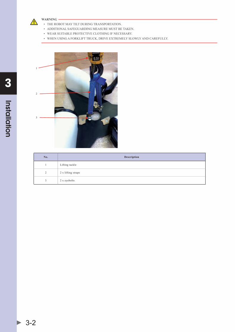
Therobotmustbeliftedandtransportedbyusingliftingtackleorforklifttruck.Twoliftingstrapshastobeattachedintotwoeyeboltsthatarescrewedintothebaseplate.Theliftingstrapshastobelongenoughandmustberoutedinsuchawaythattherobotisnotdamaged.
3
Installa
tion
3-2
WARNING • THEROBOTMAYTILTDURINGTRANSPORTATION. • ADDITIONALSAFEGUARDINGMEASUREMUSTBETAKEN. • WEARSUITABLEPROTECTIVECLOTHINGIFNECESSARY. • WHENUSINGAFORKLIFTTRUCK,DRIVEEXTREMELYSLOWLYANDCAREFULLY.
1
2
3
No. Description
1 Liftingtackle
2 2xliftingstraps
3 2xeyebolts

3
Installa
tion
3-3
2. Mounting the robotThemountingsurfacefortherobotmustbemachinedandofanappropriatequality.It'salsopossibletousealevellingelementtoaligntherobot.ThreeM20boltsareneededtomountingtherobottotheframe,exactboltlengthdependsonframelayout.ThetighteningtorqueofaM206.8boltis300Nm.
Thebelowfigureshowsthemountingpatternfromtherobot.
NOTE Itisadvisabletoputonemotoroftherobotinlinewiththedirectionofthetransportbelttomakeprogrammingeasier.
3
Installa
tion
3-4
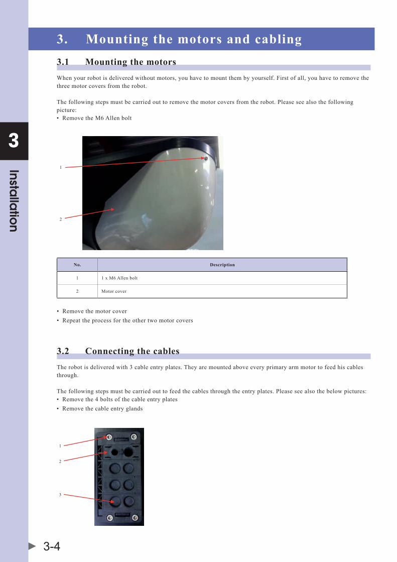
3. Mounting the motors and cabling3.1 Mounting the motorsWhenyourrobotisdeliveredwithoutmotors,youhavetomountthembyyourself.Firstofall,youhavetoremovethethreemotorcoversfromtherobot.
Thefollowingstepsmustbecarriedouttoremovethemotorcoversfromtherobot.Pleaseseealsothefollowingpicture:• RemovetheM6Allenbolt
1
2
No. Description
1 1xM6Allenbolt
2 Motorcover
• Removethemotorcover• Repeattheprocessfortheothertwomotorcovers
3.2 Connecting the cablesTherobotisdeliveredwith3cableentryplates.Theyaremountedaboveeveryprimaryarmmotortofeedhiscablesthrough.
Thefollowingstepsmustbecarriedouttofeedthecablesthroughtheentryplates.Pleaseseealsothebelowpictures:• Removethe4boltsofthecableentryplates• Removethecableentryglands
1
2
3

3
Installa
tion
3-5
No. Description
1 4xM5Allenbolt
2 Cableentryglands
3 Blindthule
• Insertthecablesintotheopeningofthemotorcover• Connectthecables
• Clampthecableentryglandsaroundthecableandslideitbackintothecableentryplate.Afterwardsalsoslidethe blindthulebackintothecableentryplate• Mountthecableentryplateonthebaseplate,usingthe4M5Allenbolts
3.3 Mounting the motor covers• Mountthecoverinthemachinedgroove• InstalltheAllenM6boltinthecoverbracketandtighten• Repeattheprocessfortheothertwomotorcovers• Themotorcoversarenowmounted
2
1
No. Description
1 Coverbracket
2 Machinedgroove

3
Installa
tion
3-6
3.4 Mounting the rotation motor or gearbox with his adaptor ringThissectionisapplicableonlytotheCR_UGD4_XXL1300H_Rmodel(withrotationalaxis).Dependentonthetypeofrotationmotororgearboxwithrotationmotor,aspecialadaptorringformountingisincluded.
1
2
No. Description
1 Gearboxormotor
2 Adaptorring
Nowmounttheadaptorring(withthemotororgearbox)onthelowersideofthebaseplatefromtherobotwiththeincludedboltsandrings.
1
2
No. Description
1 Lowersideofthebaseplate
2 Rotationadaptorringwithmotororgearbox

3
Installa
tion
3-7
4. Assembling the secondary arms4.1 Make an assemblyBeforemountingthesecondaryarmsontherobot,wehavetopre-assemblethemasshownonthebelowfigure,sothatwegetanarmassembly.
1
2
3
No. Description
1 Sanitarycupholderincl.ballbearingcup
2 Springpackage
3 Secondaryarm
Repeatthisactionfortheother2armsets.
WARNING • INCORRECTMOUNTEDSPRINGSCANJUMPAWAY. • WEARSUITABLEPROTECTIVECLOTHINGANDSAFETYGLASSES. • NEVERPULLTHESPRINGSFURTHERAPARTTHANNECESSARYWHENMOUNTINGTHEARMASSEMBLYONTHE PRIMARYARMORTCPBALLJOINTS. • REPLACESPRINGSAFTEROVERSTRETCHING.

3
Installa
tion
3-8
4.2 Mount the arm assembly on the robotFormounting,pullasecondaryarmwithhiscupholderovertheballjointoftheprimaryarm.Nowpullthearmsapartwiththeincluded"secondaryarmexpander"againsttheforceofthespringinordertoputthesecondarmoverthesecondballjointoftheprimaryarm.
No. Description
1 Secondaryarmexpander
ThenrepeatthisactionfortheTCP(seebelowpicture).
1
No. Description
1 TCP-ToolCenterPoint(withorwithoutrotationalaxis)
Repeatthisactionfortheother2secondaryarmassembly's.Nowyourrobotmechaniciscompletelyinstalled.

3
Installa
tion
3-9
5. Mounting the rotational axis on the gearbox shaftThissectionisapplicableonlytotheCR_UGD4_XXL1300H_Rmodel(withrotationalaxis).
Pleaseperformthefollowingstepsfirst.• Extendtherotationalaxistoitsentirelength,thenretractthesameandcheckwhetheritiseasytooperateorwhether someresistanceoccurs
NOTE Alightirregularresistanceisnormalandcausedbythemanufacturingtolerancesofthetubes.Theaxisisruninduringthefirst150hoursofoperation.Incaseofproblems,pleasechecktheaxisfordamageorcontactyourOMRONrepresentative.
1
2
No. Description
1 Clampingbushwithbolts
2 Rotationalaxis
ReleasethetwoM5Allenboltswhicharemountedintotheclampingbush(seeabovepicture).
Indeliverycondition,anextrafillbushislocatedintheclampingbush.Measureyourmotor/gearboxaxisanddetermineifyouneedtheextrafillbush.
1
2

3
Installa
tion
3-10
No. Description
1 Motororgearshaft
2 Topconnectorrotationalaxis
Nowpushthetopconnectorintotheshaftuntilthetopconnectorcomesintoitsstoppositionontheshaft.TightenthetwoM5Allenboltswith7Nm.
Therotationalaxisisnowmounted.
6. CalibrationNoteveryrobotthatisdeliverediscalibrated.Ifyouwanttocalibratetherobotbyyourself,acalibrationkitwithaspecialtoolisavailable(showninthebelowpicture).ThecalibrationsetcanbeorderedasCR_ART.1098
No. Description
1 Calibrationset
Thefollowingstepsmustbecarriedouttoputthethreeupperarmsfromtherobotinthezeroposition.Please,seethebelowpictures:
• Makesureallthesecondaryarmsaredisassembled• Releasethemotorbrakeandmakesurealltheprimaryarmsarerotateddownfarenough,sothecalibrationtool couldbemounted• Slidethecalibrationtoolonthebaseplateasshowninthenextpicture• Nowtightenthestarnutuntilthetoolisfixed

3
Installa
tion
3-11
• Releasethemotorbrakefromtheselectedmotorandpushtheupperarmwithhisballjointagainstthecalibrationas shownintheabovepicture• Nowfixthemotorbrakefromtheselectedmotor• Repeatthecalibrationstepsfortheothertwoprimaryarms• Removethetool
WARNING • CALIBRATINGTHEROBOTMUSTBECARRIEDOUTBYQUALIFIEDPROGRAMMINGPERSONNELONLY,ASTHIS REQUIRESANEXCELLENTLEVELOFKNOWLEDGEOFTHECONTROLSYSTEM. • WHENCARRYINGOUTTHEHOMINGYOURSELF,THISMUSTBECARRIEDOUTEXACTLYINTHEWAYANDTHE ORDERTHATTHEYAREDESCRIBED.
• Nowalltheprimaryarmsareinzeropositionfromthekinematicmodel• Nowputtheencodervaluesfromtheservomotorsin0º• Checkthattheangleindicatedforthethreemotorsis0º(±0.1°)• Yourrobotisnowcalibrated
7. Gripper interface7.1 With rotational axisThebelowfigureshowsthegripperconnectionsizesfortheCR_UGD4_XXL1300H_Rrobot(withrotationalaxis)accordingtoISO9409-1-A31,5.

3
Installa
tion
3-12
7.2 Without rotational axisThebelowfigureshowsthegripperconnectionsizesfortheCR_UGD4_XXL1300H_NRrobot(withoutrotationalaxis).
Thedesignofthegripperthatismountedundertherobothavegreatinfluenceontheperformanceoftherobot.BoththeweightofthegripperandthedistanceofthecenterofgravityofthegrippertotheTCPbasepointhavenegativeinfluenceonthefinalperformanceoftherobot.
Ifyouneedtoinstallcablingforthegripper,pleasefollowthefollowingsteps:• Mountthecablesonthebaseplateorframe,neartheturningpointfromtheprimaryarmonthegearbox• Mountthecablesontheprimaryarm,withty-rapsorclampingparts• Keepabigloopatthehingepointfromtheprimaryandsecondaryarm• Mountthecablesonthesecondaryarm,withty-rapsorclampingparts• Keepabigloopfromthelowestmountingpointatthesecondaryarmtilltheconnectiononthegripper

Chapter 4 Maintenance
Contents
1. Periodic maintenance 4-11.1 Springs 4-1
1.2 Ball bearing cups 4-2
1.3 Rotational axis 4-2
2. Cleaning the robot 4-4
3. Spare parts 4-4


4
Ma
intena
nce
4-1
1. Periodic maintenanceBeforeworkingontherobot,pleasebeensuredthatthemachinewheretherobotisbuiltin,istotallyswitchedoff.
DANGER • SWITCHOFFTHEMACHINE(SYSTEM)WHERETHEROBOTISBUILTIN(E.G.WITHAPADLOCK)TOPREVENTIT FROMBEINGSWITCHEDONAGAIN. • LABELTHEMACHINE(SYSTEM)WITHASIGNINDICATIONTHATWORKISINPROGRESS.THISSIGNMUST REMAININPLACE,EVENDURINGTEMPORARYINTERRUPTIONSTOTHEWORK. • THEEMERGENCYSTOPFROMTHEMACHINE(SYSTEM)MUSTREMAINACTIVE.IFSAFETYFUNCTIONSOR SAFEGUARDSAREDEACTIVATEDDURINGMAINTENANCEORREPAIRWORK,THEYMUSTBEREACTIVATED IMMEDIATELYAFTERTHEWORKISCOMPLETED.
1.1 SpringsHowtomaintainthesprings:• Thespringshastobereplacedevery3800workinghoursoronceayear• Whentherobotisfallapart,checkthespringsondamages• OnlyusespringsdeliveredbyOMRON,otherwisetheguaranteewillexpire• Replacespringsafteroverstretching• Forspareparts,seeSection 3 Spare partsinthischapter
WARNING • INCORRECTMOUNTEDSPRINGSCANJUMPAWAY. • WEARSUITABLEPROTECTIVECLOTHINGANDSAFETYGLASSES. • NEVERPULLTHESPRINGSFURTHERAPARTTHANNECESSARYWHENMOUNTINGTHEARMASSEMBLYONTHE PRIMARYARMORTCPBALLJOINTS.
Howtodisassemblethesprings:• Disassemblethesecondaryarmsfromtherobotwiththe"secondaryarmexpander"• Replacethesprings• Forre-assemblingthesecondaryarms,seeSection 4 Assembling the secondary armsinChapter3

4
Ma
intena
nce
4-2
1.2 Ball bearing cupsTheballbearingcupshasthesamelifetimeasthesprings.Werecommendtoexchangetheseatthesametimeasthesprings.
Howtomaintaintheballbearingcups:• Theballbearingcupshastobereplacedevery3800workinghoursoronceayear• Whentheballbearingcupsmakesqueakingnoises,takeofthesecondaryarmassembly’sandcleanthecupswith pressedair• Do not lubricate the ball bearing cups!
Forinstructionstoreplacetheballbearingcups,seebelowpicture:
1
No. Description
1 M6bolt
• ScrewanM6boltinthebacksidefromthecupholder• Nowtheballbearingcupwillcomeout
1.3 Rotational axisTheplainbearingsontherotationalaxiswearwithtimesothatbacklashstartstooccurontherotationalaxis.Howfasttheplainbearingsbecomeworndependsstronglyonthefollowingfactors:• Theworkingpath• Thepayload• Thespeedoftherobot• Therotationactions
WhendoIhavetoexchangetheplainbearings?• Ifthereisalotofplayontherotationalaxis• Every3000workinghoursoronceayear
Forinstructionstoreplacetheplainbearings,seethebelowpicture:
1
2

4
Ma
intena
nce
4-3
No. Description
1 Sliderblock
2 M6boltwithwasher
• UnscrewthetwoM6boltswithwasherandtakeofthebolts
• Removethetwotubes(sometimesthetubeswillclampinsidethesliderblock,useasmallplastichammertorelease them)
1
No. Description
1 Plainbearing
• Exchangetheoldplainbearingswiththenewones• Putbackthetwotubesontherotationalaxis• MountthetubeswiththetwoM6boltsincludingwashers
WARNING • PLAINBEARINGSHASTOBEMOUNTEDVERYCAREFULLY. • WRONGMOUNTEDPLAINBEARINGSMAYDAMAGE. • EXTENDTHEROTATIONALAXISTOITSENTIRELENGTH,THENRETRACTTHESAMEANDCHECKWHETHERITIS EASYTOOPERATEORWHETHERSOMERESISTANCEOCCURS.

4
Ma
intena
nce
4-4
2. Cleaning the robotCleantherobotbywashingwithsoftclothorsponge.Usesoapormilddetergentandwarmwaterfollowedbyclearwaterrinse.Foroilandgreasestainsusealcoholwithsoftcloth.Donotuseahighpressurewatercleaner,oranyotherhighpressurecleaningdevice.
3. Spare parts
DescriptionOMRON Part No.
CR_UGD4_XXL1300H
Primaryarmset •2xballbearing•1xdowelpin•1xprimaryarm
CR_ART.1239
Secondaryarmset •2xsecondaryarm•2xspringpackage
CR_ART.1240
Ballbearingcups •12xballbearingcup CR_ART.1124
Springpackage •6xspring•12xspringholder
CR_ART.1123
Splinepartrotationalaxis •1xsplinepartrotationalaxis CR_ART.1241
Plainbearingrotationalaxis •1xplainbearing CR_ART.1128
Cardancoupling •1xcardancoupling(insideballbearingmadeofstainlesssteel)
CR_ART.1382
Clampingbushwithbolts •1xtopclamp22mmwithbolts CR_ART.1495
TCP-ToolCenterPoint •1xTCP•6xsanitaryballjoint
CR_ART.1269
4
Ma
intena
nce
4-5
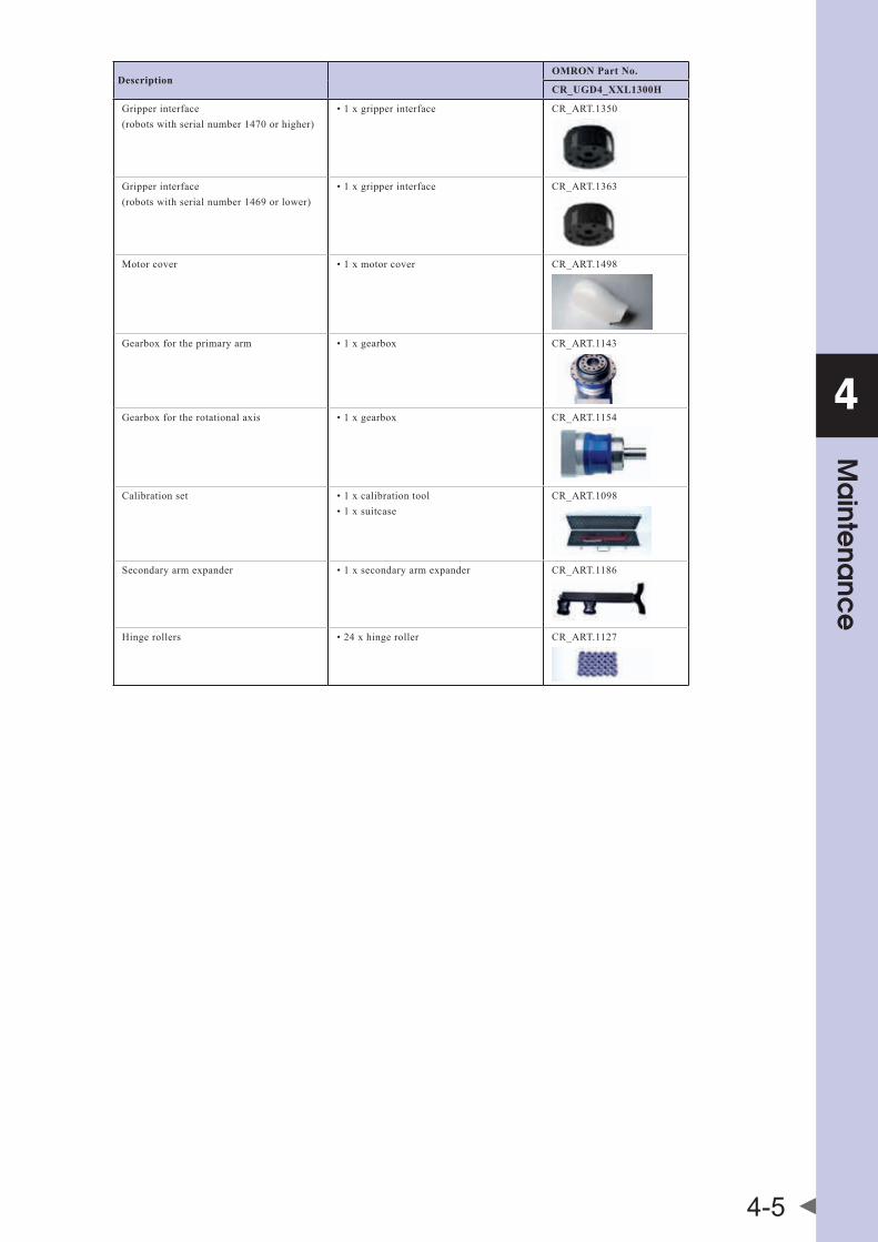
DescriptionOMRON Part No.
CR_UGD4_XXL1300H
Gripperinterface (robotswithserialnumber1470orhigher)
•1xgripperinterface CR_ART.1350
Gripperinterface (robotswithserialnumber1469orlower)
•1xgripperinterface CR_ART.1363
Motorcover •1xmotorcover CR_ART.1498
Gearboxfortheprimaryarm •1xgearbox CR_ART.1143
Gearboxfortherotationalaxis •1xgearbox CR_ART.1154
Calibrationset •1xcalibrationtool•1xsuitcase
CR_ART.1098
Secondaryarmexpander •1xsecondaryarmexpander CR_ART.1186
Hingerollers •24xhingeroller CR_ART.1127


Chapter 5 Robot settings
Contents
1. Kinematics 5-1
2. Workspace 5-2
3. Software limits 5-3


5
Rob
ot se
ttings
5-1
1. KinematicsThekinematicsparametersfortheCR_UGD4_XXL1300Hrobotareshownbelow.Settheseparameterscorrespondingtothecontrollersettings.
WARNING IFTHEKINEMATICSPARAMETERSARENOTSETPROPERLY,THISMAYCAUSETHEROBOTTOMALFUNCTION.SO,BESURETOSETTHESEPARAMETERSCORRECTLY.

5
Rob
ot se
ttings
5-2
2. WorkspaceTheworkspaceparametersfortheCR_UGD4_XXL1300Hrobotareshownbelow.Settheseparameterscorrespondingtothecontrollersettings.
WARNING IFTHEWORKSPACEPARAMETERSARENOTSETPROPERLY,THISMAYCAUSETHEROBOTTOMALFUNCTION.SO,BESURETOSETTHESEPARAMETERSCORRECTLY.
Zu + offset: -790 mm with rotational axis / -741 mm without rotational axis Distance from the Z-axis origin position to the tool flangeRcy: 650 mm Radius of the cylinder Hcy: 300 mm Height of the cylinder Rco: 390 mm Radius of the frustum cone of underside Hco: 150 mm Height of the frustum cone
Zu + offset
Rcy
Hcy
Hco
Rcy
Rco
Workspace parameters

5
Rob
ot se
ttings
5-3
3. Software limitsThesoftwarelimitsfortheCR_UGD4_XXL1300Hrobotareshownbelow.
WARNING IFTHEα-,β- OR γ-AXISSOFTLIMITISSETINCORRECTLY,THEARMMAYCOLLIDEWITHTHEROBOTBASEORBASEPREPAREDBYTHEUSER,CAUSINGBREAKAGE.SO,BESURETOSETTHESOFTLIMITSCORRECTLY.
Minus directionsoft limit [-30°]
Plus directionsoft limit [88°]


Chapter 6 Specifications
Contents
1. Basic specifications 6-11.1 Cycle time 6-1
2. External view and dimensions 6-2
3. Design specifications 6-33.1 Occupation area of robot 6-3
3.2 Software design 6-4
3.2.1 Dimensionsandlimits 6-5


6
Spe
cific
atio
ns
6-1
1. Basic specifications
Robot model CR_UDG4_XXL1300H_R CR_UDG4_XXL1300H_NR
Working volume
X, Y axis Stroke Ø1300mm
Z axis Stroke 300mm (max. Ø1300mm)/450mm (center Ø780mm)
θ axis Rotation range±180° (default setting, it can be
changed)
Servo motorArm 1, 2, 3 3000W
Rotational axis 4 1000W
Repeatability*1X, Y, Z axis ±1mm
θ axis ±0.3°
Maximum through-put*2 90 CPM*3
Maximum payload 8kg
Gearbox ratioX, Y, Z axis 1:38,5
θ axis 1:20
θ axis torque limitation 26 Nm
User tubing (outer diameter) Ø8*4
Travel limit Soft limit
Noise level < 68 dB (A)
Ambient temperature 5ºC to 45ºC
Relative humidity Max. 90%
Protection class IP65
Weight 90kg
*1: This is the value at a constant ambient temperature. *2: With 0.1kg payload. When reciprocating 305mm in horizontal and 25mm in vertical directions. *3: CPM: Cycle per minutes. Check the note 2 for the cycle definition. *4: Only for the air suctioning. The air injection is not allowed.
1.1 Cycle time
Z1
Y
Z2
P&P path Payload Cycle time
25 x 305 x 25 mm (Z1 x Y x Z2) 1 kg 0.47 s
25 x 305 x 25 mm (Z1 x Y x Z2)8 kg
0.90 s
200 x 1000 x 200 mm (Z1 x Y x Z2) 1.5 s

6
Spe
cific
atio
ns
6-2
2. External view and dimensions
NOTE Robotswithserialnumber1469orlowerhavedifferentgripperdimensions.Refertosection“3.2Gripperinterface”inthischapterformoredetailedinformationaboutdimensions.

6
Spe
cific
atio
ns
6-3
3. Design specifications3.1 Occupation area of robotIftherobotisintegratedintothemachineitmustbeconsideredwhatthereachisofallrobotpartstopreventcollisionwithotherpartsinthemachine.
WhentheTCPmovestoitsouterpositions,theprimaryandsecondaryarmscanriseabovethebaseplate,takecarethatnomechanicalobstructionsareintheareasindicatedinthebelowpicture.
400
100
200
420
600
WARNING IFMECHANICALOBSTRUCTIONSAREINTHEINDICATEDAREA,THEROBOTORTHEOTHERMACHINEPARTSCOULD BE DAMAGED.

6
Spe
cific
atio
ns
6-4
3.2 Software designThearmlengthsandpitchcirclesoftherotationpointsareshowninthebelowpicture.
Upper arm length440 mm
Lower arm length950 mm
Lower arm rotation pointscircle diameter 140 mm
Upper arm rotation pointscircle diameter 295 mm
Flange offset59 mm with rotational axis
10 mm without rotational axis

6
Spe
cific
atio
ns
6-5
3.2.1 Dimensions and limits
Description Value
With rotational axis Without rotational axis
Negativesoftwarelimit -30º
Positivesoftwarelimit 88º
Tb-z(topbaseplatetozeroposition) 110mm
Z-tw(zeropositiontoballbearings) 731mm
Flangeoffset 59mm 10mm


Revision history
A manual revision code appears as a suffix to the catalog number on the front cover manual.
The following table outlines the changes made to the manual during each revision.
Revision code Date Description
01 July 2015 Original production
01A July 2016 Secondary arm expander was included
01B October 2016 New gripper interface was included
01C May 2017 Spare parts section was updated. Robot dimensions were updated
01D September 2017 Basic specifications section was updated

Cat. No. I201E-EN-01D Note: Specifications subject to change without notice.
Authorized Distributor:
Printed in Europe