Embed Size (px)
Citation preview
1LE COPY [ NO.
N 62 5754Q
TOI'TICAL iELORANDtJIS
ITATIONAL ADVISORY COMMITTEE FOR AERONATJTIOS
No. 540
MATHEMATICAL Ai'T EXPERIMENTAL INVESTIGATIOT OF HEAT CONTROL
AND POVER IIWREASE IN AIR-COOLED AIRCRAFT EiTGILTES
By F. Gosslau
From Zeitschrift fr Flugtechnik unci MotorIuftschlffahrt October 7, 1028
cuE
çQF* . Te'•
Washintcn No ye mb e I', 1029
. '
https://ntrs.nasa.gov/search.jsp?R=19930090901 2018-08-08T00:15:25+00:00Z
NATIONAL ADVISORY C01ThiITTEE FOR AERONAUTICS.
TECHNICAL MEMORANDUM NO. 540.
MATHEMATICAL AND E)TERIMENTAL INVESTIGATION OF HEAT CONTROL
AND POWER INCREASE IN AIR-COOLED AIRCRAFT ENGINES.*
By F. Gosslau.
For more than a decade the vertical water-cooled engine
was the German standard aircraft engine. It did not seem possi-
ble for its fuel consumption, power output per unit volume,
length of life and reliability to be surpassed or even equaled
by an air--cooled engine. In the last few years, however, there
has been active competition between air-cooled. and water-cooled
engines and it can now be confidently asserted that, up to 600
hp, the advantage lies with the radial air-cooled engine.**
This is indicated by the fact that nowadays hardly an engine
within this range is designed for water cooling, while anew
radial air-cooled engine appears almost every month. In Germany
and elsewhere well-known firms, which had formerly made vertical
water-cooled engines exclusively, have turned their attention to
the manufacture of radial air-cooled engines.
The first high-powered. radial air-cooled engine was the
Bristol "Jupiter" which was designed. in 1918. The latest air-
planes of the German Lufthansa are equipped with this engine, *' ? Rechnerjsche und experimentelle Untersuchngen &ber Warme'beh-
errschung und Leistungssteigeuflg in luftgekuhltefl Flugmotoren-zylindern" from Zeitschrift fur Flugtechnik und Motorluftschif-fahrt, Oct. 7, 1928, pp. 461-466. **Cf. V.D.I., 1925, p.1329; 1926, p.1G?2; Z.F.M., 1927, p.63.

N.A.C.A. Technical hemorandun ITo. 540
:ihich nor, furnishes over 500 hp. The three-engine Junkers air-
p1ae tt Hermann Kohl" and the four-engine Superv1alU are also
equipped with this engine.
Although the mechanical requirements of crank shafts, con-
necting rods, piston pin.s and bearings can be calculated for
the highest engine powers, the designer could not answer the
question as to whether a cylinder exceeding the customary dimen-
sions could. be satisfactorily cooled by air, because he did not
know the numerical relations between the air velocity, tenipera-
ture of the cylinder walls, heat dissipation, cylinder dimensions
and type of construction.
Experimental Plant
In order to determine these rel.ations, I had an experi-
mental plant (Fig. i) installed on behalf of the Siemens and
Halske Company in their laboratory. The experimental cylinder
Was exposed. to the air stream of a wind tunnel. The compression
chamber was heated by an electrically heated oil bath kept con-
stantly in motion by a stirrer (Fig. 2). The Wall temperatures
were measured by thermocouples. The air stream was produced
by a seven-kilowatt blower. The air flowed through a current
rectifier (honeycomb), diffuser, air chamber with quieting
sieves and a nozzle. - By varying the heating current with the
aid of resistances and by varying the velocity of the air stream
with the aid of throttling disks in the suction nipple of the
blower, the mutual relations of the air velocity, wall tempera-
N.A.C.A. Technical iemoraridum I'To. 540 3
ture and heat could be determined.
A- the beginning of the experiments in 1925, there were
still many different types of cylinders in use. For our ex-peri-
ments vie select.ed a few typ ical cylinders which are shown in
Figures 3-10. These were used as test cylinders in our experi-
mental plant. With them we determined the values required for
the law of similarity of heat transmission, in order to be able
to judge cylinders of' larger dimensions. These values were then
plotted as characteristic curves (Fig. 11), which are here
straight lines, as in many other heat-transfer problems with log-
arithmic coordinates, enabling simple extrapolation. Figure 12
shows the characteristic curves for several cylinders of 100 nmi
in.) diimeter at a mean temperature difference of 150°C
(270°F) between the cylinder wall and the air strean. The curves
represent the quantities of heat carried away per hour from one
square meter for every degree centigrade (1.8°F) of' temperature
difference for a variable velocity of the air stream. The bot-
tom curve applies to a steel cylinder closed at the top, while
the top curve applies to a cylinder vith an aluminum head. The
latter, for example, has a cooling effect three times as great
at an air velocity of 50 mIs (164 ft./sec.) as the formerly used
steel cylinder.
Discussion of the Cylinder Types
The causes of the great differences in the heat given off
by the different types of cylinders were then investigated. The

N.A.C.A. Technical Memorandum No. 540
4
different cylin-
the compression
13-17). Obstruc-
ire variations,
very gradual
temperature distribution along the walls of the
ders was determined for the same temperature of
chamber and the same air-stream velocity (Figs.
tions to the heat flow produced sudden temperat
while good. heat conduction was indicated by the
variation o± the temperature curve.
The clearest example was furnished by the cylinder with the
removable cast-iron head (Figs. 5-6). Between the cyliflder and
the cylinder head there was a thin copper-asbestos gasket, which
offered a very high resistance to the downward flow of the heat.
This obstructioii had. a decided effect on the temperature curve
and threw the burden of heat dissipation almost entirely on the
cylinder head. With the deep aluminum head (Figs. 7-8) the
equalization of the temperatures is assured b the active flow
of heat in the thick walls. Particularly evident is the down-
ward flow of heat in the aluminum head without fins (Figs. 9-10).
In the experiments it wa found .that an aluminum head without
fins always dispersed somewhat more heat than a removable cast-
iron head. The fins on the aluminum head increased. the heat
dispersion threefold and reduced the mean temperature correspond-
ingly.
Inferences by Analogy
Figure 19 shows the logarithmic curves which characteri.ze
this type of cylinder. it shows the specific heat dissipation.
for all practical air velocities, temperatures and cylinder diam-

N.A.C.A. Technical Memorandum No. 540 5
eters. It also illustrates two important general laws:
1. The specific heat dissipation increases with the air
velocity rapidly at first and then more slowly.
2. Other conditions remaining the same, the specific heat
dissipation decreases with increasing cylinder diameter.
Verification of the Experimental Results
Knovrledge of the specific heat dissipation enables one to
determine beforehand the heat characteristics of a projected
cylinder. The heat calculations of a cylinder involve three
steps:
1. Calculation of the heat load. Figures 20-22 show the
results obtained with three different cylinders.
2. Determination of the specific heat dissipation a of a
given cylinder type (Fig. i9).
3. Calculation of the temperature from the temperature
difference between the cylinder wall and cooling air required
for a balance between the heat load and the heat dissipation.
The heat load in the cylinder of the small Siemens radial
engine is 226,700 kcal/m2 /h. The temperature reached by the
cylinder in cooling air at 0°C (32°F) and 45 rn/s (148 ft./sec.)
velocity is obtained by dividing this number by the correspond:
ing value of a, which is 1200 kcal/m2 /h/°O in the present
case. It is 189°C (372.2°F). Measurements with this cylinder
at 1°C (33.8°F) gave a mean' temperature of 177°C (350.6°F), mak-
w.A.C.A. Technical Memorandum No 540
ing the discrepancy between the calculated and measured mean
temperatures only 12°C (21.6°F). This is a very satisfactory
result, as compared with the former complete uncertainty of the
temperature of a newly designed cylinder.
In order to test further the range of applicability of the
measurements, we made advance calculations for a newly designed
cylinder with 3- times the volumetric capacity of the small cyl-
inder tested in the wind tunnel. It was some months before the
large cylinder was tested. It was then found. that the previous-
ly calculated. temperature differed only a few degrees from that
measured in the middle of the cylinder head while in operation.
Maximum Power of Present-Day Cylinders
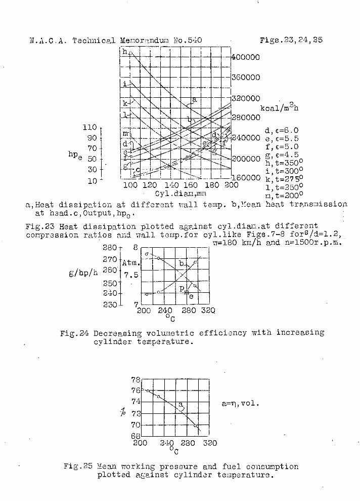
Figure 23 shows that the heat loads increase with increas-
ing tylinder diameter for the same stroke-bore ratio. On the
other hand. the experiments show that the amount of heat dissi-
pate decreases under the same conditions. Hence it follows that,
under otherwise similar conditions, the wall temperatures in-
crease with increasing cylinder dimensions.
Efficiency tests by Professor Gibson show, however, that
the temperature of a cylinder cannot be indefinitely increased
without finally having an unfavorable effect on its efficiency
(Gibson, Aero-Engine Efficiencies," The Aeronautical Society,
London). For example, the volumetric efficiency decreases with
increasing cylinder temperature (Fig. 24), and the fuel consump-

N.A.C.A. Technical Memorandum io. 540
7
tion increases with decreasing mean piston pressure (Fig. 25).
Hence with increasing cylinder diameter temperatures are ap-
proached which greatly reduce the power and economy. In this
connection either the cylinder temperature or the degree of
cooling is the limiting factor for the cylinder power. The max-
imum running temperature cannot be definitely prescribed. Just
as in the designing of machinery, however, certain stresses ale
0 designated as admissible, about 300 0. (572 F). may be consdered
an admissible temperature for an air-cooled cylinder head. With
this limiting temperature the maximum power of a single air-
cooled cylinder without supercharging is about 70 horsepower.
Increasing the Power by Supercharging
The maximum cylinder power will not remain long at the
above figure, however. Any decrease in efficiency may be pre .-
vented by supercharging. The turbo-blowers flow commonly used
with radial engines may be regarded as a development of the ro-
tary mixture distiibuter originally used by Armstrong for air-
cooled radial engines. While the mixture distributer revolves
at the speed of the crank shaft, the speed of the supercharger
rotor has already been increased to 15,000 r.p.m. An essential
task of the supercharger is always to assure an adequate charge
even at a high cylinder temperature. Hence it enables the in-
creasing of the admissible temperature of air-cooled cylinders.
Since it is driven, however, by gears from the crank shaft, the

A.C.A. Technical iIe:orandun JO. 540 8
power required to operate it is lost to the propeller. The me-
chanical efficiency of the engine is therefore reduced and its
fuel consumption increased.
It is more economical to operate the supercharger by tur-
bines utilizing the heat of the exhaust gases (Fig. 26). Such
superchargers have been used principally for high-altitude fly-
ing. Their speed ranges from 20,000 to 40,000 r.p.m. and. adapts
itself automatically to the atmospheric pressure. They consid-
erably reduce the noise of the exhaust. In order to avoid in-
jury to the engines, these high-altitude superchargers can be
used for only brief periods of time to increase the engine
powe near the ground.
Longer Strokes Rather than Larger Bores
Supposing the power of a short-stroke cylinder has been
increased to the temperature limit, then, due to the decreasing
coefficient of heat dissipation, any further increase of the
bore would result in still higher temperatures and. uneconomical
operation. On the other hand, lengthening the stroke would not
affect the coefficient of heat dissipation nor the economy of
operation, even at a higher power.
In this connection, if we compare the results obtained with
two air-cooled radial engines, as given in the acaompaflyiflg ta-
ble, we find that engine A reached the temperature limit and.
even exceeded it as a fuel consumption of 248 g/hp/hr (0.547
N.A.C.A. Technical Memorandum No. 540
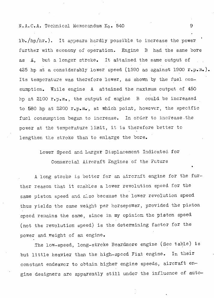
lb./hp/hr.). It appears hardly possible to increase the power
further with economy of operation. Engine B had. the same bore
as A, but a longer stroke. It attained the same output of
425 hp at a considerably lower speed (1590 as against 1900 r.p.m.).
Its temperature was therefore lower, as shown by the fuel con-
suniption. While engine A attained the maximum output of 450
hp at 2100 r.p.m., the output of engine B could be increased
to 580 hp at 2200 r.p.m., at which point, however, the specific
fuel consumption began to increase. In order to increase .the
power at the temperature limit, it is therefore better to
lengthen the stroke than to enlarge the bore.
Lower Speed and Larger Displacement Indicated for
Commercial Aircraft Engines of the Future
A long stroke is better for an aircraft engine for the fur-
ther reason that it enables a lower revolution speed for the
Caine piston speed ad also because the lower revolution speed
thus yields the same weight per horsepower, provided the piston
speed remains the same, since in my opiniom the piston speed
(not the revolution speed) is the determining factor for the
power and weight of an engine.
.The low-speed, long-stroke Beardinore engine (See table) is
but little heavier than the high-speed Fiat engine. In their
constant endeavor to obtain, higher engine speeds, aircraft en-
gine designers are apparently still under the influence of auto-
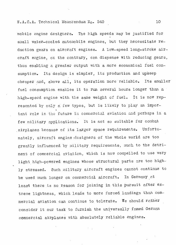
N.A.C.A. Technical Memorandum i1o. 540 10
mobile engine designers. The high speeds may be justified for
small water-cooled automobile engines, but they iecessitate re-
duction gears on aircraft engines. A low-speed, long-stroke air-
craft engine, on the contrary, can dispense with reducing gears,
thus enabling a greater output with a more economical fuel con-
sumption. Its design is simpler, its production and upkeep
cheaper and, above all, its operation more reliable. Its smaller
fuel consumption enables it to run several hours longer than a
high-speed engine with the same weight of fuel. It is now rep-
resented by only a few types, but is likely to play an impor-
tant role in the future in commercial aviatipn and. perhaps in a
few military applications. It is not so suitable for combat
airplanes because of its larger space requirements. Unfortu-
nately, aircraft engine de signers of the whole world are too
greatly influenced by military requirements, much to the detri-
ment of commercial aviation, which is now compelled to use very
light high-powered engines whose structural parts are too high-
ly stressed. Such military aircraft engines cannot continue to
be used much longer on commercial aircraft. In Germany at
least there is no reason for joining in this pursuit after ex-
treme lightness, which leads to more forced. landings than com-
mercial aviation can continue to tolerate. We should rather
consider it our task to furnish the universally famed German
commercial airplanes with absolutely reliable engines.

iI.A.C.A. Technical M 5morandum No. 540
11
Racing Engines
In contrast with this still lacking type the Bristol Mer-
cury is a very highly perfected engine for racing airplanes and
at the sane time the most powerful air-cooled 9-cylinder engine
in the world. It is a good. demonstration of what high powers
can be developed by airr,00led cylinders. It became known at
the 1927 international seaclane races in Venice (Zeitschrift des
Vereines deutscher Ingenicure, 1927, p.1740). All the means
known to us today were empiyed to increase its power.
1. The cylenciers had shrunk-on light-metal heads, each
with four ialves and push-rod balance.
2. The crank-shaft speed was increased to 2800 r.p.m.
3. A bevel reduction gear reduced the speed. ef the propel-
ler shaft to 1400 r.p.m.
4. A mechanically driyen turbo-blower of 65 hp at 22,000
r.p.m. Was built into the rear end. of the crank case.
This engine developed. not less than 920 hp, o more than
100 hp for each air-cooled cylinder.

N.A.C.A. Technical Memoruidum No. 540
12
Resulte Obtained with Different Engines
E n g i n e d s N b Nmax 1max bmax
- Radial engine A 146 146 1 425 iool 9.25 2481450 2100 250
B 146 190 1.3 425 1590 10.1 228 580 2200 240
E n i n e d s - N01 fl Crçj b N 1 Eg Gf4h
iat 980 hp 170 200 1.1? 81.6 2000 13.3 265 13 0.91 1!97
Eeardmore900hp 219 317.5 l.45j150 1350 14.3 220j_17.611.O 1.89
d, cylinder bore (nm)
s, piston stroke (m)
N, total engine output (.hp)
N cyi, output per cylinder (pip)
n, revolution speed (r.p.ri.
Pm, mean pressure (atm.).
c, , mean piston speed (mIs)
b, fuel consumption (g/hp/h)
N 1 , output per liter of fuel(hp)
Eg , empty weight per horsepower (kg/hp)
Gf, •flying weight per horsepower (kg/h)
Translation by Dwight M. Miner, National Advisory Committee for Aeronautics.
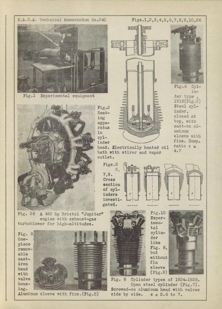
.A.C.A. Techr1ic1 Wernorndum No.540
Figs.l,2,3,4,5, 6,7,8,9,10,26
'4ri AIjr
ii ..L ... ••.... der type 19l8(Fi.3)
1 Fig.2 Steelcy].-
Heat- inder,
ing :i ':. closed at
top, with appa-: :..1 --- cast-on al-
• ratus
/ , _. .
. in . ••••. uxninum
r
: head. Electrically heated oil ratio e • .bath with stirer and vapor outlet.
Figs.3 ° ..
• . . section
•-r gated. -.. -
Fi... . A 450 hp Bristol 'Jupiter' F1.lO
engine with exhaust-gas • Exper-turboblower for :ih-a1titudes. imen-
- tal
6: iii cylin-
One- iiH fl ii der -
ÔU hhij like
remov- Fig. 8,.
able ____ but
__________ without
head ____ sleeve
with . (Fig.9)
valve . -_______ :. . •'.. _... er types of l9;4-l5. hous- ., ____ Open steel cylinder (Fig.?). ing. . . ._.- .. . Screwed-on alumlxrnm head with valves Aluminum 3iVC witL fi.(fi.) side by side. € 5.6 to 7.

N. A. C . A. Technical Memorandum No . 540
Figs.11 & 12
5000
2500
ci-ç-
1000
50C 10000 50000 250000
w d p
d,cyl. dia; vi,air ve1ocity;c,coef.of heat transmission; ,coef.of heat flow;p,density;q,viscosity.
1. Cylinder like Fig.7-8,depth of fins 22 mm (0.87 in.) 2. ii ,but with fins 10 mm deep. 3.
It , 2 mm U
4 It It II 9-10. 5 II U 11 5-6. 6. II It II 3_4
Fig.11 Characteristic curves.
I
11 ...D-
1200
rE9l000
800
H bOO
LJ 400
200
00 20 40 60
rn/s
a, Aluminium head with ribs 22 mm deep.
b,Aluminum head with ribs 10 mm deep.
c,Aluminum head with ribs 2 mm deep.
d,Aluminum head without ribs. e,C1osed steel cylinder.
Fig.12 Specific heat dissipation plotted against air velocity for cylinder diameter,d=l00 mm and a
mean temperature difference of 150°C between cylinder wall and air stream.
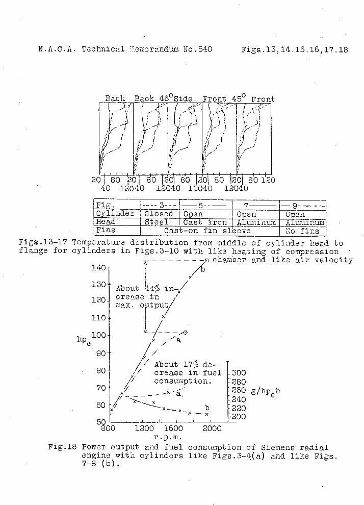
N.A.C.A. Technical cmoranduri No.540 Figs.13,14.15.16,17.18
Back Back 45°Side Front 45° Front
7720 j 80 Oj 80 1201 80 201 80 201 80 120 40 12040 12040 12040 12040
1 9p.n Open ad Steel Cast
___ ___
Fins Cast-on fin sleeve Lo fins
Fig.l3-l7 Temperature distribution from micid.le of cylinaer head to flange for cylinders in Figs.3-l0 with like heating of compression
- -------j chamber and like 140 /b
air velocity
/
130 About 44% in-/
120 crease in // max. a tput/
hp00
About 17% de-80 // crease in fuel 300
// consumption. 280 70 260 g/hp5h
/'T 240 60f/,
Ix b 02 200
50 I I 800 1200 1600 2000
r.p.m. Fig.18 Power output and fuel consumption of Siemens radial
engine with cylinders like Figs.3 .-4(a) and like Figs. 7-8 (b).

-100 mm 125 " -150 " •r -175 O( -\ ft c__1J
rH
'50 0 N60150
80_i!_l75 •1 ft
125
N.A.C.A. Technical e2oranduii; No.540
Figs .19,20,21,22
\JI1II__i
z1
- --
-- -
Mean tea1ip.
t t w ti r---
1200 800 400 0 40 80 okca1/m2h0O1 r1i/s
Fig.19 Specific heat dissption plotted against mean temperature and air velocity for various cylinder
diameters.Loer group of curves is for cylinders shon in Figs.3-4,upper group for cylinders in F.igs.7-8.
(a c
2 a,•Q=226700 kcal/mh \Id I. '\ g ( \\ d ,/d,10mri b,Q=278000 [I\JJ_L/ e,100 ' c,Q=204300
f,154 LJ 4i g,188 Fig.20 Fig.22
Fig.21
Fig.20-22 Heat loads of different cylinders.
N.A.C.A. Technical Meriorindum No.540
Figs.23, 24,25
110
90 70
hPe 50
30 - 10
- - --r:Iif:IIIIiIII - - -t-- -
- 4 . I-d, c=6.0
240000 e,€=5.5 f, 5.0
200000
i,'t=300° 160000 k t=2750
100 120 140 160 180 200 i't=250° Cy1.diaxi.7mm m,t=2000
a,Heat dissipation at different at haad.c,Output,hp0.
Fig.23 Heat dissipation plotted compression ratios and wall terr
28Or 8
270 Atm. g/bp/h 260'
250 240 '200 240 280 32Q
00
Fig.24 Decreasing voluctric efficiency with increasing cylinder temperature.
:00000
360000
3200002,
kcal/mTh 80000
1M2
wall temp. b,Mean heat transmissioi
against cyl.dian.at different p.for cyl.like Figs.7-8 for/d=1.2,
w=l80 km/h and n=l500r.p.m.
7
7 vol. '70 7
7
6200 240 280 320
00
Fig.25 Mean working pressure and fuel consumption plotted against cylinder temperature.